11 en Mmtk Wireless Communication-Tower Handout
26
ITRAINONLINE COMMUNICATION TOWER HANDOUT Developed by: Alberto Escudero Pascual IT !"# Table o$ Co%te%ts 1. Abou t th is d ocument.................................................................. ............................................ 2 1.1 Copyright information.......................................................................................................2 1.2 Degree of Difficulty..........................................................................................................2 1.3 Acknowledgements..........................................................................................................2 2. Introduc tion......................................................... .................................................................. 2 3. The standard ......................................................................................................................... 3 . Definitions! Towers and "asts...............................................................................................3 #. Types of towers and masts....................................................................................................3 #.1 "onop ole tower............................................................................................................... # #.2 $elf supporting tower.......................................................................................................# #.3 %uyed mast..................................................................................................................... & &. 'ow to choose a tower type..................................................................................................& &.1 Antenna load.................................................................................................................... & &.2 To wer footprint........................................................................... ...................................... ( &.3 'eight of tower..................................................................... ........................................... ( &. )udge t............................................................................................................................. ( (. To wer location ....................................................................................................................... ( *. The base............................................................................................................................... * +. Digging the hole.................................................................... ................................................ * 1,. )uilding a re-bar cage.........................................................................................................+ 11. The Concrete foundation...................................................................................................11 11.1 Concrete composition..................................................................................................11 11.2 "iing concrete............................................................................................................11 11.3 /ouring the concrete....................................................................................................12 11. 'ydration .....................................................................................................................13 11.# Curing..........................................................................................................................13 11.& Concrete strength........................................................................................................13 12. Ancho rs ............................................................................................................................ 1 13. Assembling the tower........................................................................................................1 13.1 Inspection of tower sections........................................................................................1 13.2 /re-assembly on the ground........................................................................................1# 13.3 %in pole.......................................................................................................................1# 13. Assembling of high towers...........................................................................................1& 1. %uy cables........................................................................................................................ 1( 1.1 Types of guy wires.......................................................................................................1( 1.2 /re-load in guy cables.................................................................................................1* 1.3 T er mination of gu ys.................................................. .................................................... 1+ 1. Tightening the guy cables............................................................................................2, 1.# "easuring the tension.................................................................................................2, 1.& "easuring tower plumb...............................................................................................21 1.( Temporary guys...........................................................................................................22 1#. Climbing ............................................................................................................................ 22 1&. 0ightening protection.........................................................................................................23 1&.1 Direct hits.....................................................................................................................23 1&.2 Indirect hits..................................................................................................................23 1(. Corrosion...........................................................................................................................2 1(.1 Corrosion preention...................................................................................................2# 1(.1.1 Antioidant oint compound...................................................................................2# 1(.1.2 Cathodic protection...............................................................................................2# 2*(3#33#.odt 0ast updated! "ay 1 2,,& Aailable online from http!www .itrainonline.orgitrainonlinemmtk 1
-
Upload
shadishwaren-parameswaran -
Category
Documents
-
view
21 -
download
0
description
network
Transcript of 11 en Mmtk Wireless Communication-Tower Handout

7/17/2019 11 en Mmtk Wireless Communication-Tower Handout
http://slidepdf.com/reader/full/11-en-mmtk-wireless-communication-tower-handout 1/26
ITRAINONLINECOMMUNICATION TOWER HANDOUT
Developed by: Alberto Escudero Pascual IT !"#
Table o$ Co%te%ts1. About this document.............................................................................................................. 2
1.1 Copyright information.......................................................................................................21.2 Degree of Difficulty..........................................................................................................21.3 Acknowledgements..........................................................................................................2
2. Introduction........................................................................................................................... 23. The standard......................................................................................................................... 3. Definitions! Towers and "asts...............................................................................................3
#. Types of towers and masts....................................................................................................3#.1 "onopole tower............................................................................................................... ##.2 $elf supporting tower.......................................................................................................##.3 %uyed mast..................................................................................................................... &
&. 'ow to choose a tower type..................................................................................................&&.1 Antenna load.................................................................................................................... &&.2 Tower footprint................................................................................................................. (&.3 'eight of tower................................................................................................................ (&. )udget............................................................................................................................. (
(. Tower location....................................................................................................................... (*. The base............................................................................................................................... *+. Digging the hole.................................................................................................................... *1,. )uilding a re-bar cage.........................................................................................................+
11. The Concrete foundation...................................................................................................1111.1 Concrete composition..................................................................................................1111.2 "iing concrete............................................................................................................1111.3 /ouring the concrete....................................................................................................1211. 'ydration .....................................................................................................................1311.# Curing..........................................................................................................................1311.& Concrete strength........................................................................................................13
12. Anchors ............................................................................................................................ 113. Assembling the tower........................................................................................................1
13.1 Inspection of tower sections........................................................................................113.2 /re-assembly on the ground........................................................................................1#13.3 %in pole.......................................................................................................................1#13. Assembling of high towers...........................................................................................1&
1. %uy cables........................................................................................................................ 1(1.1 Types of guy wires.......................................................................................................1(1.2 /re-load in guy cables.................................................................................................1*1.3 Termination of guys...................................................................................................... 1+1. Tightening the guy cables............................................................................................2,1.# "easuring the tension.................................................................................................2,1.& "easuring tower plumb...............................................................................................211.( Temporary guys...........................................................................................................22
1#. Climbing............................................................................................................................ 221&. 0ightening protection.........................................................................................................23
1&.1 Direct hits.....................................................................................................................231&.2 Indirect hits..................................................................................................................23
1(. Corrosion...........................................................................................................................2
1(.1 Corrosion preention...................................................................................................2#1(.1.1 Antioidant oint compound...................................................................................2#1(.1.2 Cathodic protection...............................................................................................2#
2*(3#33#.odt0ast updated! "ay 1 2,,& Aailable online from http!www.itrainonline.orgitrainonlinemmtk
1
7/17/2019 11 en Mmtk Wireless Communication-Tower Handout
http://slidepdf.com/reader/full/11-en-mmtk-wireless-communication-tower-handout 2/26
1*. "aintenance......................................................................................................................2&1+. Conclusions....................................................................................................................... 2&
&' About t()s docu*e%t
These materials are part of the Itrain4nline "ultimedia Training 5it 6""T57. The ""T5proides an integrated set of multimedia training materials and resources to supportcommunity media8 community multimedia centres8 telecentres8 and other initiaties usinginformation and communications technologies 6ICTs7 to empower communities and supportdeelopment work.
1.1 Copyright information
This unit is made aailable under the Creatie Commons Attribution-$hareAlike 2.# 0icense.To find out how you may use these materials please read the copyright statement includedwith this unit or see http!creatiecommons.orglicensesby-sa2.#.
1.2 Degree of Difficulty
The degree of difficulty of this unit is )asic.
1.3 Acknowledgements
Constructing towers and masts re9uires years of eperience. Therefore8 I hae collected thebest online resources from eperienced tower builders. Three people deseres specialacknowledgement!
"r. "ark D. 0owell 6:10478 the author of the N1LO Guide Tower Topic Summary . The guide isa digest of his own eperience and the TowerTalk forum8 an email forum with thousands of eperienced tower builders.$ource! http!www.9sl.netn1lo
"r. $tee "orris 65(0;C78 a professional tower installer8 the founder and moderator of theTowerTalk forum.$ource! http!www.championradio.cominstalls.html
0ast but not least8 "r <ick 5un=e8 an eperienced tower builder and founder of Colusa:>TInc8 he has put together an ecellent site of his 150 ft self supporting tower constructionproect.
$ource! http!www.do-it-yourself-tower.com
2*(3#33#.odt0ast updated! "ay 1 2,,& Aailable online from http!www.itrainonline.orgitrainonlinemmtk
2

7/17/2019 11 en Mmtk Wireless Communication-Tower Handout
http://slidepdf.com/reader/full/11-en-mmtk-wireless-communication-tower-handout 3/26
+' I%troduct)o%
<adio masts and communication towers are typically tall constructions specially designed to
carry antennas for radio communication. $uch radio communication includes teleision8 radio8%$" and Internet traffic.
Towers and masts are used in numerous applications in wireless networks from broadbandpoint-to-point systems to 0"<1 networks. Towers and masts are often re9uired to raiseantennas aboe tree lines and roof tops for line-of-sight connections.
This unit is a general guide8 practical oriented8 for establishing a communication tower or mast. The guide is applicable both for self supporting towers and guyed masts.
,' T(e sta%dard
The Structural Standards for Steel Antenna Towers and Antenna Supporting Structures6A:$ITIA 222-?-1++& was published in "arch 1++& by the TIA 6Telecommunications Industry Association7. The obectie of the TIA 222-? document was to proide a set of minimumcriteria for specifying and designing steel antenna towers and antenna supporting structures.
The document includes topics as wind loading8 paint8 guys8 foundations8 bolt tightening8climbing and maintenance. The document is not free of charge 6costs about 1,, @$D78 but itis highly recommended to hae a copy of it when you are planning to erect a communicationtowermast.
"' De$)%)t)o%s: To-ers a%d MastsIn engineering terms8 a to-er is a sel$.support)%/ structure while a *ast in supported bystays or /uys.
The terms towerB and mastB are often used for the same type of structure8 which of coursecan cause confusion. Tower and mast hae different definitions in American and )ritish>nglish. In American Englis8 both types of structures are often called towers8 while in !ritisEnglis8 people always use mast instead.
To aoid this confusion8 in this unit we are using the engineering terms!• tower self-supporting
• mast supported by stays or guys.
1 0and "obile <adio - wireless for speciali=ed applications as tai8 police or emergencyserices
2*(3#33#.odt0ast updated! "ay 1 2,,& Aailable online from http!www.itrainonline.orgitrainonlinemmtk
3

7/17/2019 11 en Mmtk Wireless Communication-Tower Handout
http://slidepdf.com/reader/full/11-en-mmtk-wireless-communication-tower-handout 4/26
0' Types o$ to-ers a%d *asts
This section presents the three most common types of towersmasts that are used today inwireless communication sel$.support)%/ tower8 *o%opole and /uyed mast1.
Image 1! The three most common types of communication towersmasts.
Source" #enters for $isease #ontrol and %re&ention ' ttp"((www)cdc)go& *
5.1 Monopole tower
"onopoles are hollow tapered poles made of galani=ed steel Theyare constructed of slip ointed welded-tubes and can be up to 2,,feet 6&,m7. Due to its construction8 they are epensie tomanufacture but simple to erect.
"onopoles are primarily used in urban enironments where there islimited space aailable for the footprint2 of the tower base. Themaimum footprint of a 2,, feet monopole is appro. && feet 622m7
Image 2! A monopole tower Source" ttp"((commons)wikimedia)org
1 :otice that the guyedB *ast pictures only a set of guys 6this is for graphical reasons only72 The physical space needed for the deployment.
2*(3#33#.odt0ast updated! "ay 1 2,,& Aailable online from http!www.itrainonline.orgitrainonlinemmtk
7/17/2019 11 en Mmtk Wireless Communication-Tower Handout
http://slidepdf.com/reader/full/11-en-mmtk-wireless-communication-tower-handout 5/26
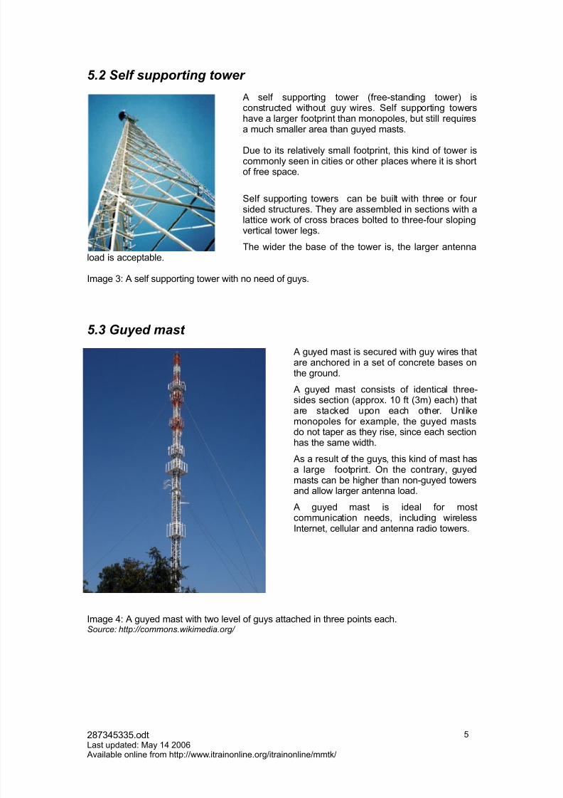
5.2 Self supporting tower
A self supporting tower 6free-standing tower7 isconstructed without guy wires. $elf supporting towershae a larger footprint than monopoles8 but still re9uiresa much smaller area than guyed masts.
Due to its relatiely small footprint8 this kind of tower iscommonly seen in cities or other places where it is shortof free space.
$elf supporting towers can be built with three or four sided structures. They are assembled in sections with alattice work of cross braces bolted to three-four slopingertical tower legs.
The wider the base of the tower is8 the larger antennaload is acceptable.
Image 3! A self supporting tower with no need of guys.
5.3 uyed mast
A guyed mast is secured with guy wires thatare anchored in a set of concrete bases onthe ground.
A guyed mast consists of identical three-sides section 6appro. 1, ft 63m7 each7 thatare stacked upon each other. @nlike
monopoles for eample8 the guyed mastsdo not taper as they rise8 since each sectionhas the same width.
As a result of the guys8 this kind of mast hasa large footprint. 4n the contrary8 guyedmasts can be higher than non-guyed towersand allow larger antenna load.
A guyed mast is ideal for mostcommunication needs8 including wirelessInternet8 cellular and antenna radio towers.
Image ! A guyed mast with two leel of guys attached in three points each.Source" ttp"((commons)wikimedia)org(
2*(3#33#.odt0ast updated! "ay 1 2,,& Aailable online from http!www.itrainonline.orgitrainonlinemmtk
#
7/17/2019 11 en Mmtk Wireless Communication-Tower Handout
http://slidepdf.com/reader/full/11-en-mmtk-wireless-communication-tower-handout 6/26
#' Ho- to c(oose a to-er type
There are in general four maor consideration when selecting the type of tower for your deployment!
1. Antenna load
2. Tower footprint
3. 'eight of tower
. )udget
!.1 Antenna load
The antenna loading capability of a tower depends on the structure of the tower. The moresurface area of antennas8 coaial cables8 brackets and other e9uipment mounted on the
tower and eposed to the wind8 the more robust tower is re9uired.
To make sure that your e9uipment adds a load less than that maimum allowed alue for your tower8 you must estimate the effectie wind load for your e9uipment. The wind load is proportional to the area of the eposed structure and to the distance from theattachment to the ground. Cured and perforated shapes 6grids and trusses7 offer less windresistance and are therefore preferred to achiee a low wind load. $olid dishes are 9uiteulnerable to wind load and should be aoided in windy enironments.
The aerage wind speed of the site must also be taken into consideration. The aerage windspeed depends on where on the earth the site is located8 the altitude and type surroundings6rural or city7. 4nline statistical data is aailable from meteorological institutes.
There are many ways to calculate the wind load8 some are better than others. The latestB andprobably most accurate method is specified in the latest I>A-222 standard specification.
!.2 "ower footprint
The footprint of a tower is the amount of free space on the ground that is re9uired for theinstallation. Depending on the structure of the tower8 it re9uires more or less space for installation.
?or tall guyed masts 6E1,,feet8 3,m78 each guy anchor is typically 1,-1#m from the base of the mast. ?or a mast with 3 guy wires per leel8 that results in a footprint of appro. +,-2,,m2 .
!.3 #eight of tower
If you need a structure that is less than , feet8 you can in fact eliminate the epense andadditional work that is re9uired for guying it. Instead you can bracket mount the tower to ahouse or garage roof een.
As mentioned earlier8 adding guys cables to a structure will allow higher height.
2*(3#33#.odt0ast updated! "ay 1 2,,& Aailable online from http!www.itrainonline.orgitrainonlinemmtk
&

7/17/2019 11 en Mmtk Wireless Communication-Tower Handout
http://slidepdf.com/reader/full/11-en-mmtk-wireless-communication-tower-handout 7/26
!.$ %udget
A general rule of thumb is!
The smaller the tower base8 the more costly to purchase and install the towerB"onopoles hae the smallest footprint of all towers8 and is hence the most epensie type of tower to install. It is followed by self supported towers and then guyed masts which re9uire thelargest footprints.
Additionally8 depending on the tower type you choose8 certain tools8 machinery and cranes areneeded to assemble the tower which must be taken into consideration in the final budget.
1' To-er locat)o%
Fhen selecting the physical location of the towermast8 there are a set of things that you
should bear in mind. :aturally8 you must make sure that you hae the necessary free spaceon the ground where the tower will be placed. Check the specifications of the towermast thatyou aim to purchase for the si=e of the footprint. The ideal site for a towermast is a flat8 leel field. 'oweer8 any reasonably leel space8 inwhich there is sufficient space for the base foundations8 can be utili=ed. The site should befree from obstructions like trees and buildings. :ot only the spot for the tower needs to beclear8 also the surrounding area as you will need some free space when assembling the tower.
Do not forget that trees hae roots. Digging a hole through a massie root system is not adream.
"edium si=ed and tall towersmasts normally re9uire massie digging since concretefoundations must be put in place. Always call for underground utilities ceck to make surethat there is no infrastructure dough down at the place you hae planned for your towermast.
Also8 if the tower is high8 always check with the regulators in the country if you need to applyfor a license andor register the tower to any authority. If the site is close to an airport8 thereare special regulations that need to be followed.
2*(3#33#.odt0ast updated! "ay 1 2,,& Aailable online from http!www.itrainonline.orgitrainonlinemmtk
(

7/17/2019 11 en Mmtk Wireless Communication-Tower Handout
http://slidepdf.com/reader/full/11-en-mmtk-wireless-communication-tower-handout 8/26
2' T(e base
All towers need a steady base to stand upon. The purpose of establishing a base under atower is to keep the tower from sinking under its own weight and the pressure of the guy
wires 6if such are being used7.
"ost towersmasts are established on top of a co%crete base that has a pier pin or boltembedded in it. A less common solution is to hae a tower section embedded in the concretebase. The first option with a pier pinbolt embedded has the following adantages!
1. The bottom section of the tower does not need to be plumbed2. :o need to worry about water in the tower legs 6it will naturally pour down the legs and
out though the weep holes in the base plate73. It gies the tower the fleibility to turn a bit from side to side to absorb tor9ue in high
winds 6resulting in less stress on the bottom section of the tower7. :o need to worry about how the base sectionB will interfere with the steel re-bar in the
tower base
$elf supported towers 6no guyed wired7 need one central concrete foundation with as manyattachment points as the sides of the tower structure. In that way8 a three-sided self supportedtower needs three attachment points 6anchors7 in the concrete foundation.
A guyed tower needs one concrete base for each guy wire and one central base for the tower itself.
The following sections 6$ection +-1178 present a step-by-step process for establishing aconcrete foundation for a self-supporting tower. The procedure for making concrete bases for a guyed mast is ery much the same8 ecept for the number and si=e of the bases and theattachment points.
$ection 1 focuses on guy wires for masts 6not needed in self-supporting towers7.
3' D)//)%/ t(e (ole
The digging of the base hole can be done by hand if the tower is small enough. As the tower grows8 the amount of soil to be dough increases rapidly. It is highly recommended to hire abackhoe 6with an eperienced operator7 for digging a hole for a tower in large scale.
There are some issues that you should keep in mind before you start to dig!
U%d)sturbed so)lIt is important that the base is surrounded by undisturbedB soil to aoid it from shifting.Therefore8 make sure that you do not remoe more soil from the sides than what isnecessary.If necessary8 hae the backhoe operator to dig a hole with rough dimensions and then build upthe walls by hand.
Lar/er volu*e t(a% e4pected Always epect that the final olume of the hole will be larger than you first epected. Diggingwith a backhoe is not a precision work and you will normally end up with a hole with larger dimensions that what you planned for. That means that more concrete is going to be needed.
Typically8 soil will fall off from the sides into the hole. The hole will be +ell saped after youhae remoed the loose soil. The result will be that you may need up to least 2#G more filling
to your hole.
2*(3#33#.odt0ast updated! "ay 1 2,,& Aailable online from http!www.itrainonline.orgitrainonlinemmtk
*
7/17/2019 11 en Mmtk Wireless Communication-Tower Handout
http://slidepdf.com/reader/full/11-en-mmtk-wireless-communication-tower-handout 9/26
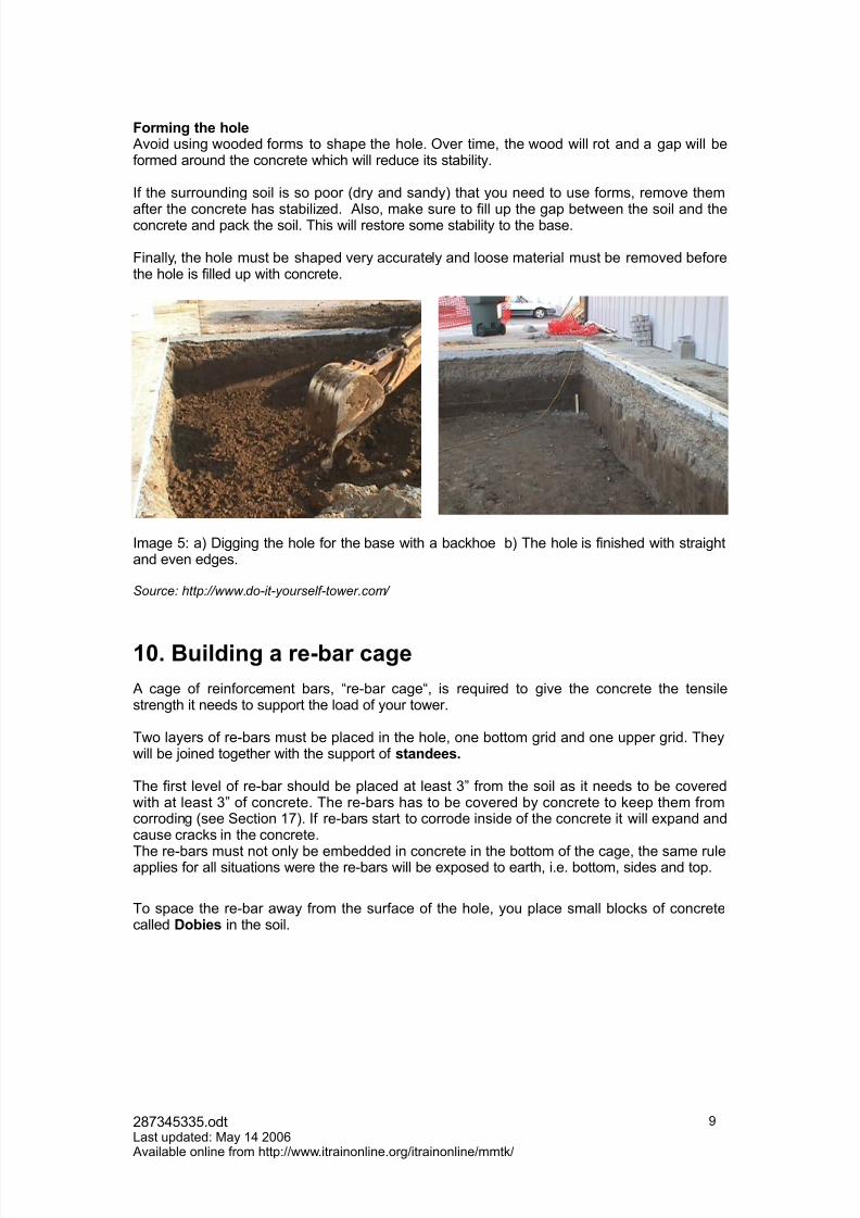
5or*)%/ t(e (ole Aoid using wooded forms to shape the hole. 4er time8 the wood will rot and a gap will beformed around the concrete which will reduce its stability.
If the surrounding soil is so poor 6dry and sandy7 that you need to use forms8 remoe them
after the concrete has stabili=ed. Also8 make sure to fill up the gap between the soil and theconcrete and pack the soil. This will restore some stability to the base.
?inally8 the hole must be shaped ery accurately and loose material must be remoed beforethe hole is filled up with concrete.
Image #! a7 Digging the hole for the base with a backhoe b7 The hole is finished with straightand een edges.
Source" ttp"((www)do,it,yourself,tower)com(
&6' 7u)ld)%/ a re.bar ca/e
A cage of reinforcement bars8 re-bar cage8 is re9uired to gie the concrete the tensilestrength it needs to support the load of your tower.
Two layers of re-bars must be placed in the hole8 one bottom grid and one upper grid. Theywill be oined together with the support of sta%dees'
The first leel of re-bar should be placed at least 3B from the soil as it needs to be coeredwith at least 3B of concrete. The re-bars has to be coered by concrete to keep them fromcorroding 6see $ection 1(7. If re-bars start to corrode inside of the concrete it will epand andcause cracks in the concrete.
The re-bars must not only be embedded in concrete in the bottom of the cage8 the same ruleapplies for all situations were the re-bars will be eposed to earth8 i.e. bottom8 sides and top.
To space the re-bar away from the surface of the hole8 you place small blocks of concretecalled Dob)es in the soil.
2*(3#33#.odt0ast updated! "ay 1 2,,& Aailable online from http!www.itrainonline.orgitrainonlinemmtk
+

7/17/2019 11 en Mmtk Wireless Communication-Tower Handout
http://slidepdf.com/reader/full/11-en-mmtk-wireless-communication-tower-handout 10/26
After placing the dobies on the soil8 build a grid of re-bar and tie them together with wire or plastic tie-wraps.Do %ot -eld as t(at -ea8e%s t(e re.bars'
Image & a7 @sing Dobies to create space between re-bars and the soil. b7 @sing wires to tiethe re-bars to a grid.Source" ttp"((www)do,it,yourself,tower)com(
<e-bars are si=ed in reference to1*H steps in diameter. In that way a re-bar is 12Hdiameter 6J 1*7 anda & re-bar is 3H 6&J 1*7 diameter. As a rule of the thumb8 do not use re-bars less than #6#*H diameter7.
Fhen the bottom grid of re-bars is in place8 it is time to mount the standees. The standees willbe tighten to the lower grid to support the upper grid. The standees must be customi=edaccording to your specification and normally come from the re-bar supplier.
Fith the help of etra dobies8 place the -,!olts inside of the re-bar cage. The tower will beattached to the K-bolts. The lower part of the K-bolts get embedded in the concrete with oneend sticking up aboe the foundation.
Fhen the standees are securely tied in place8 the upper grid will be assembled on top of themin the same manner as the lower grid.
Image (! a7 Two layer of re-bars inter-connected with standees. b7 K-)olts that will connect thebase of the tower to the concrete foundation.
Source" ttp"((www)do,it,yourself,tower)com(
4n top of the upper grid of re-bars8 the triangular shaped structure of re-bars is formed to host
the base of the tower.
Fhen the re-bar cage is in place8 it is time to fill it up with concrete.
2*(3#33#.odt0ast updated! "ay 1 2,,& Aailable online from http!www.itrainonline.orgitrainonlinemmtk
1,
7/17/2019 11 en Mmtk Wireless Communication-Tower Handout
http://slidepdf.com/reader/full/11-en-mmtk-wireless-communication-tower-handout 11/26
&&' T(e Co%crete $ou%dat)o%
Concrete is a miture of paste and a//re/ates. The paste8 composed of cement and water8coats the surface of the fine and coarse aggregates. Portla%d ce*e%t is the most commontype of cement and consists of a miture of oides of calcium8 silicon and aluminium.
Through a chemical reaction called (ydrat)o%8 the paste hardens and gains strength to formthe rock-like mass known as concrete. 'ydration is the key issue behind the success of concrete its plastic and mouldable state when newly mied but hard and strong as rock whenhardened.
11.1 Concrete composition
Typically8 a concrete mi should be about 1,-1# G cement8 &, - (# G aggregate and 1# - 2,G water. All ingredients must be carefully selected to create a good final product.
"ost natural water that is drinkable and has no taste or odor8 can be used for makingconcrete. >en some waters that are not drinkable are still suitable for concrete. >cessieimpurities in the miing water will affect the setting time8 the concrete strength8 may causeefflorescence and staining. Additionally8 it may cause corrosion of the re-bar structure whichwill cause olume instability and reduced durability.Concrete specifications normally states limits for the leel of c(lor)des sulp(ates al8al)sa%d sol)ds in miing water. The aggregates must also be carefully chosen. The type and si=e of aggregates affects thethickness of the concrete. Aggregates are inert granular materials such as sa%d /ravel8 or crus(ed sto%e'
11.2 Mi&ing concrete
Kust like digging a hole8 miing concrete can be done manually or by machine. Fhen castinga small concrete foundation8 the concrete can easily be mied up by hand while larger basesdefinitely needs machinery.
As an eample8 a *, pound 63& kg7 bag of Luickrete will make 23 cubit feet 6,8,2 m3 7 of concrete. It takes about 1, minutes to mi one bag of this in a wheelbarrow and dump it intothe base. A tower base 3M3M3M is one cubic yard which re9uires no less than , bags. Thatwould take & hours of miing by hand.
?or medium si=e bases8 it is easier to order a truck of concrete and use wheelbarrows toshuttle the concrete to the pour site. Alternatiely8 a concrete mier can be hired and used onsite.
2*(3#33#.odt0ast updated! "ay 1 2,,& Aailable online from http!www.itrainonline.orgitrainonlinemmtk
11
RE.7AR NO.NO9s
1. :eer let the re-bar get in contact with the soil2. :eer weld the re-bars8 use wires to knit instead
7/17/2019 11 en Mmtk Wireless Communication-Tower Handout
http://slidepdf.com/reader/full/11-en-mmtk-wireless-communication-tower-handout 12/26
If you are haing trouble with the truck not reaching the base ecaation8 you can collect allyour friends and set up a brigade of multiple wheelbarrows to moe the concrete to the hole. Alternatiely8 you can rent a motori=ed wheelbarrow.
?or large bases8 contract for a concrete pumper truck which can delier loads up to ,, maway from the truck.
11.3 'ouring the concrete
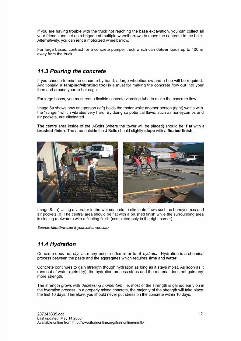
If you choose to mi the concrete by hand8 a large wheelbarrow and a hoe will be re9uired. Additionally8 a ta*p)%/v)brat)%/ tool is a must for making the concrete flow out into your form and around your re-bar cage.
?or large bases8 you must rent a fleible concrete ibrating tube to make the concrete flow.
Image *a shows how one person 6left7 holds the motor while another person 6right7 works withthe HstingerH which ibrates ery hard. )y doing so potential flaws8 such as honeycombs andair pockets8 are eliminated.
The centre area inside of the K-)olts 6where the tower will be placed7 should be $lat with abrus(ed $)%)s(. The area outside the K-)olts should slightly slope with a $loated $)%)s(.
Image *! a7 @sing a ibrator in the wet concrete to eliminate flaws such as honeycombs andair pockets. b7 The central area should be flat with a brushed finish while the surrounding areais sloping 6outwards7 with a floating finish 6completed only in the right corner7.
Source" ttp"((www)do,it,yourself,tower)com(
11.$ #ydration
Concrete does not dry. as many people often refer to8 it ydrates. 'ydration is a chemicalprocess between the paste and the aggregates which re9uires t)*e and -ater .
Concrete continues to gain strength though hydration as long as it stays moist. As soon as itruns out of water 6gets dry78 the hydration process stops and the material does not gain anymore strength.
The strength grows with decreasing momentum8 i.e. most of the strength is gained early on inthe hydration process. In a properly mied concrete8 the maority of the strength will take placethe first 1, days. Therefore8 you should neer put stress on the concrete within 1, days.
2*(3#33#.odt0ast updated! "ay 1 2,,& Aailable online from http!www.itrainonline.orgitrainonlinemmtk
12

7/17/2019 11 en Mmtk Wireless Communication-Tower Handout
http://slidepdf.com/reader/full/11-en-mmtk-wireless-communication-tower-handout 13/26
11.5 Curing
Curing is a process that aids the hydration of the concrete. Fhen the concrete is poured intothe hole it should be kept moist with a temperature of #,-(#N? 61,-2NC7. A correct curingprocess in essential for the 9uality of the concrete. %ood curing implies that eaporation of water should be preented or reduced.
11.! Concrete strength
Concrete is a ery strong material when it is placed in compression8 i.e. it can handle heayload. 'oweer8 it is etremely weak during tension. That is why we need to use reinforcementin concrete structures when tension is applied to the material.
Material "ension (psi) Compression(psi)
)ricks8 common light red , 1,,,
/ortland Cement8 1 month ,, 2,,,
/ortland Cement8 1 year #,, 3,,,
/ortland Concrete8 1month
2,, 1,,,
/ortland Concrete8 1 year ,, 2,,,
%ranite (,, 1+,,,
Table 1! The tension and compression alues of different sorts of concrete.
2*(3#33#.odt0ast updated! "ay 1 2,,& Aailable online from http!www.itrainonline.orgitrainonlinemmtk
13
CONCRETE NO.NO9s
3. ;u% on freshly poured concrete.• 5eep it coered with wet straw 6or old wet rug7 plus plastic or tar
paper.
1. >cessie (eat.• Do not pour concrete when the temperature is too high.
1. /ouring concrete into a (ole that is dry.• Fet the bottom and sides of the hole before you pour the
concrete otherwise the dry soil will suck all the water out of theconcrete. That will result in a weak mi when it cures.
1. ;tress)%/ the $res( co%crete • Do not put any stress on the tower base while the concrete is
hydrating. Do not assemble the tower too 9uickly.
1. Dry co%crete surface while cur)%/• %ie it a spray with water as often as possible to keep it wet.
7/17/2019 11 en Mmtk Wireless Communication-Tower Handout
http://slidepdf.com/reader/full/11-en-mmtk-wireless-communication-tower-handout 14/26
&+' A%c(ors
The anchor is the metallic structure that connects the guy cables to the concrete foundation. Anchors are critical infrastructure and they are truly the only thing that keeps a tower in placewhen the wind is blowing. If you lose an anchor8 you will loose a guy cable and conse9uentlythe whole tower 6can7 goes down.
The anchor can be of type earth anchorB or concrete anchorB. An earth anchor is not asstrong as a concrete anchor8 but it is easier and cheaper to install. An earth anchor should onlybe used for small masts in combination with stable soil. The strength of an earth anchor depends on the type of soil they are installed in. )y determine the type of soil you hae8 youcan estimate the pull,out rating of the anchor.$oils with clay will proide a higher pull-out strength while softer soils containing more sandand loam will gie you a lower pull-out strength. Also8 softer soil will become saturated withwater during rainfall season which will result in a much lower pull-out strength. If applicable8earth anchors can also be drilled into large rocks.
&,' Asse*bl)%/ t(e to-er Communication towers and masts are typically manufactured in sections which are puttogether on the site of the deployment. $ome models though8 normally shorter structures8 areself-erecting towers that come in one pieceB.
This section focuses on towersmasts that constitute of a set of sections that need to beassembled. $uch structures can both be self supporting tower and guyed masts.
13.1 *nspection of tower sections
)efore you start to actually assemble the tower sections8 make a thoroughly inspection of the
metal pieces to aoid working with defectie material. The inspection should be done shortlyafter the deliery of the material and before accepting them to the supplier. 0ook for thefollowing characteristics!
1. )ent or twisted sections2. Deformed or bent ends3. "is-aligned oint sleees. Felds with cracks or multiple pinholes#. %aps8 flakes or separations in the galani=ing&. "issing assembly bolts(. )ent braces*. Improperly drilled bolt holes+. 0egs that you cannot see light through which are clogged with debris
1,. <ust that is more than light surface rust. @se a flash light to peer inside of each legand looks for interior rust.
11. 0egs that hae been repaired or welded to other than the original factory brace and oint-sleee. These welds are often easily identified by surface rust.
2*(3#33#.odt0ast updated! "ay 1 2,,& Aailable online from http!www.itrainonline.orgitrainonlinemmtk
1
7/17/2019 11 en Mmtk Wireless Communication-Tower Handout
http://slidepdf.com/reader/full/11-en-mmtk-wireless-communication-tower-handout 15/26
13.2 're+assem,ly on the ground
A basic strategy when assembling towers is to brea8 do-% eery big task into many smallsubtas8s and hae a deta)led pract)cal pla%8 from start to end8 before you start to assemble
it. Do not start with a task if you do not know how to finish it.
?or guyed masts8 a set of useful tricks follows!
1. $tart by pre-assemble the tower sections on the ground8 starting with the basesections. Install the /uy attac(*e%t po)%ts but do not fully tighten all the bolts untilafter installation of the guys.
2. Calculate how long each guy cable must be and then add 1, feet 63 m7 to the result.Pre.cut all the /uys and mark each one of them with a tag to identify which guy it isintended for 61st8 2nd8 3rd etc.7.
3. /re-install the /uy /r)ps on one end of each guy cable8 but only halfway. 0eae oneside un-wrappedB so that when you raise the guy up to the guy bracket8 you caneasily slip the free end of the guy grip through the thimble and finish the wrap 9uicklywhile you are up on the tower.
13.3 in pole
A gin pole is a useful tool for lifting tower sections on top of each other. A gin pole is typically along piece of metal tubing with a pulley in the top with a set of ropes attached to it. In thebottom of the gin pole8 a bracket is attached that clamps to the leg of the tower.
Fhen the first tower section is put in place oer the concrete base8 a gin pole is mounted atthe top of that tower section. )y pulling the ropes 6by man power7 from the ground8 the ginpole allows to lift up a tower section aboe the top section of the tower and set it down ontothe preious section. "eanwhile a tower section is lifted up with the gin pole8 one or twopersons are needed in the tower to undo the bolts and to place the section correctly when it islowered.%in poles are also used for the reerse process8 when disassembling a tower.
An important issue about gin poles is the type of ropes used. It is recommended
to use a braided rope even though it is more expensive that a twisted rope. A
braided rope avoids the unwind/wind cycles that occur under load and is also fareasier to coil than a twisted rope.
Nylon is a cheaper option but it is elastic and stretches quite a bit under tension
which will reduce the control of the lifting object.
2*(3#33#.odt0ast updated! "ay 1 2,,& Aailable online from http!www.itrainonline.orgitrainonlinemmtk
1#
<ENERAL HINT; 5OR TOWER A;;EM7LIN<
Fhen installing a guyed section8 pull the guys up separately and do notattach them to the section. If eperienced8 pre-installation of the guyattachments to the tower section is a good idea though8 since that is a9uite comple task that should be aoided to do in the air.Install all bolts with the nuts on the inside of the tower. In that way you willreduce the protrusion on the outside legs and aoid getting stuck withyour climbing gear and damage both your clothes and your skin.

7/17/2019 11 en Mmtk Wireless Communication-Tower Handout
http://slidepdf.com/reader/full/11-en-mmtk-wireless-communication-tower-handout 16/26
The length of the rope should be approx. twice the height of the tower plus some
extra length at least !" feet# $!m% so that the ground crew can &eep a safe
distance away from the bottom of the tower.
'or example# for a $"" feet ("m% tower# your rope should be at least )!" feet*!m% long.
In )""+ the Telecommunications Industry Association TIA% and ,lectronicsIndustry Association ,IA% accepted and implemented a gin pole standard entitled
- Structural Standards for Installation of Antenna and Antenna Supporting
Structures" TIA/,IAN+01" 2in oles%. The aim of the standard was toimprove the safety for tower wor&ers.
13.$ Assem,ling of high towers
If the tower is ery high8 assembling of the tower sections can not be done manually with a ginpole. Then8 a crane is needed to lift up the tower sections to the right place. $till8 you needeperienced people in the tower to mount the pieces together.
Image +! @sing a crane to place the top segment on a high self-supporting tower.
&"' <uy cables
A guy cable 6or guy wire8 guy rope7 is a metallic wire that gies stability to tall structures likemasts. 4ne end of the guy is attached to the tower in an attachment point while the other end
is attached to the concrete foundation in a guy anchor.
The guy cables act like etension springs in two different ways 6modes7!
Mode &They change length relatiely easily without significant elastic stretching as the droop intem is pulled tigt. resulting in a ery low spring rate1 until all the slack is pulled out.
Mode +4nce they are tight 6the droop is pulled out78 they can still change length by stretching elastically although only with much larger changes in tension 6larger spring rate7.
1 $pring rate it the amount of force needed to compress a spring.
2*(3#33#.odt0ast updated! "ay 1 2,,& Aailable online from http!www.itrainonline.orgitrainonlinemmtk
1&

7/17/2019 11 en Mmtk Wireless Communication-Tower Handout
http://slidepdf.com/reader/full/11-en-mmtk-wireless-communication-tower-handout 17/26
1$.1 "ypes of guy wires
The most commonly used guy wires are >'$ $teel guy wires8 /hillystran and /ultrudedfiberglass.
EH; =E4tra ()/( stre%/t(> ;teel <uy-)re$pecified in the A:C$ 6American :ational$tandards Institute7 standard A$T" )22(-, withthe title /Standard Specification for ard,$rawn#opper,#lad Steel ire2 .
An >'$ steel wire is made of a set of galani=edtwisted steel strands and is the most commonlyused guy cable.
Image 1,! >'$ galani=ed guy cableP()llystra% A non-conducting guy wire material made out of 5elar 6aramid fiber7 fiber core with a /CO acket. /hillystan is both strong and light weighted.
The purposes of the /OC acket acket are!
1. To protect the cable from abrasion during installation
2. To preent moisture from wicking into the core
3. "ost importantly8 to protect the core from @O damage
Pultruded $)ber/lass/ultroded fiberglass is much more elastic than steel. In order to hae the same spring rate assteel guys and hence8 the same ability to stabili=e a tower8 the cross-sectional area of thefiberglass must be must larger 6.*3 times7 that the steel.In the case of a >'$ guy8 the e9uialent solid fiberglass rod diameter would be twice the >'$si=e you want to replace.
1$.2 're+load in guy ca,les
It is recommended that the guy wires should hae a initial tension 6pre-load7 of appro. 1,-1#G of its ultimate breaking strength1 to stretch out the slack in them. The eact amount of pre-load depends on the type of guys used and how high up in the towermast they areattached.
Fhen you add pre-load to a guy wire8 you will straighten it out as it is it is not perfectly straight
as it is. 'oweer8 due to graity8 the wire will neer be entirely straight and there will always bea concae cure een though it is pulled beyond the specified pre-load. At some point8 thestretching will make the wire to epand elastically which means that it goes from mode 1 tomode 2.
If you add too large pre-load to your wire8 you are reducing its ability to absorb additional load6from the tower moing7 before it reaches its breaking strength.
The larger the diameter of the guy8 the higher spring rate which implies that it can better resista change in length 6i.e. moement of the tower7 for the same loading force. 'oweer8 a larger diameter will make the guy wire heaier and hence8 it re9uires more pre-load tension to pullout the slack 6still 1,-1#G of the tensile strength7.In summary8 using a thicker guy wire will allow more fleing of your tower since it has a higher
spring rate8 and hence8 much larger forces are re9uired to make it change length.
1 )reaking $trength - The measured load re9uired to break a wire rope in tension.
2*(3#33#.odt0ast updated! "ay 1 2,,& Aailable online from http!www.itrainonline.orgitrainonlinemmtk
1(
7/17/2019 11 en Mmtk Wireless Communication-Tower Handout
http://slidepdf.com/reader/full/11-en-mmtk-wireless-communication-tower-handout 18/26
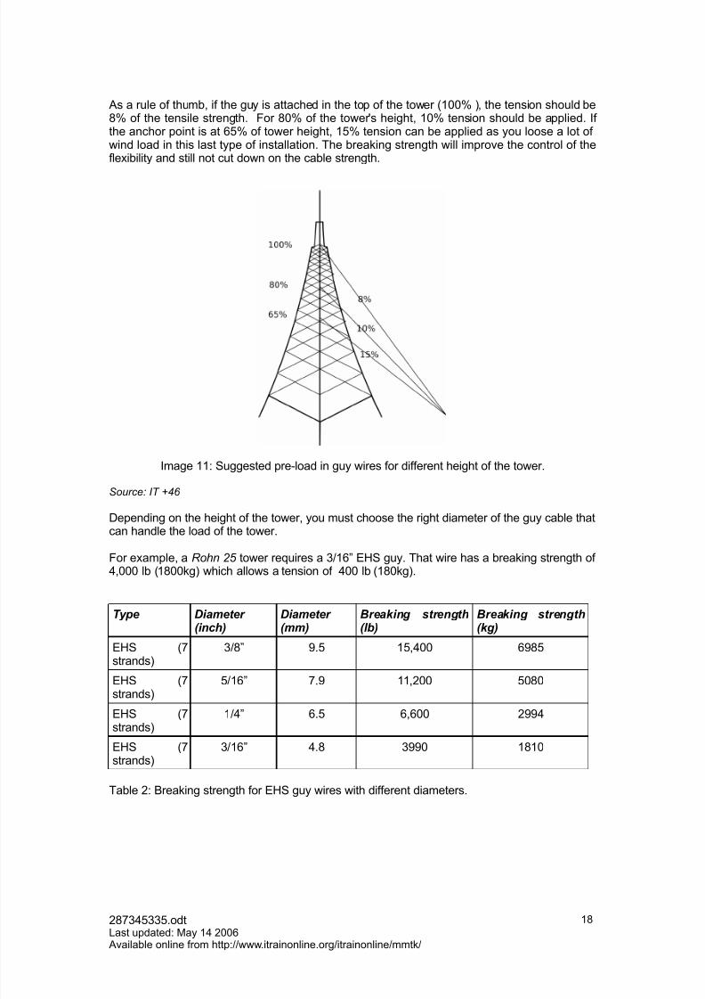
As a rule of thumb8 if the guy is attached in the top of the tower 61,,G 78 the tension should be*G of the tensile strength. ?or *,G of the towerMs height8 1,G tension should be applied. If the anchor point is at &#G of tower height8 1#G tension can be applied as you loose a lot of wind load in this last type of installation. The breaking strength will improe the control of thefleibility and still not cut down on the cable strength.
Image 11! $uggested pre-load in guy wires for different height of the tower.
Source" 3T 46
Depending on the height of the tower8 you must choose the right diameter of the guy cable thatcan handle the load of the tower.
?or eample8 a 7on 85 tower re9uires a 31&B >'$ guy. That wire has a breaking strength of 8,,, lb 61*,,kg7 which allows a tension of ,, lb 61*,kg7.
"ype Diameter (inch)
Diameter (mm)
%reaking strength(l,)
%reaking strength(kg)
>'$ 6(strands7
3*B +.# 1#8,, &+*#
>'$ 6(
strands7
#1&B (.+ 1182,, #,*,
>'$ 6(strands7
1B &.# &8&,, 2++
>'$ 6(strands7
31&B .* 3++, 1*1,
Table 2! )reaking strength for >'$ guy wires with different diameters.
2*(3#33#.odt0ast updated! "ay 1 2,,& Aailable online from http!www.itrainonline.orgitrainonlinemmtk
1*
7/17/2019 11 en Mmtk Wireless Communication-Tower Handout
http://slidepdf.com/reader/full/11-en-mmtk-wireless-communication-tower-handout 19/26
1$.3 "ermination of guys
The guy wires need to be terminated in a way so that they can be securely attached to the guyanchors.
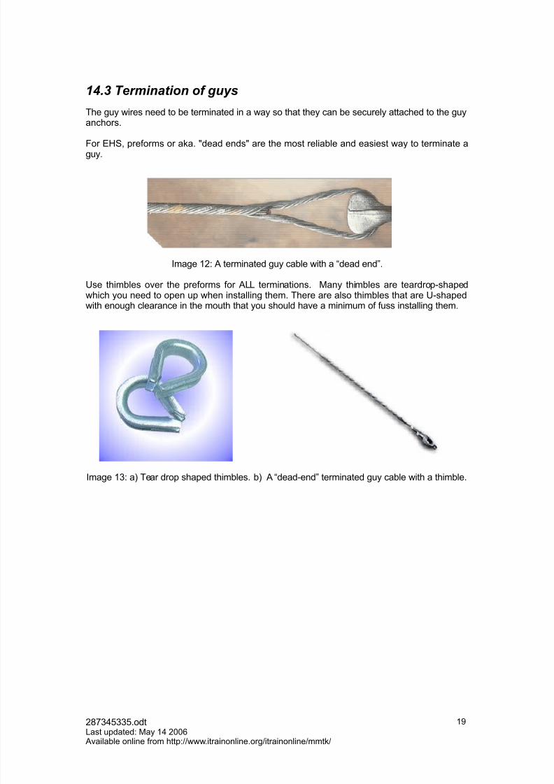
?or >'$8 preforms or aka. Hdead endsH are the most reliable and easiest way to terminate aguy.
Image 12! A terminated guy cable with a dead endB.
@se thimbles oer the preforms for A00 terminations. "any thimbles are teardrop-shapedwhich you need to open up when installing them. There are also thimbles that are @-shapedwith enough clearance in the mouth that you should hae a minimum of fuss installing them.
Image 13! a7 Tear drop shaped thimbles. b7 A dead-endB terminated guy cable with a thimble.
2*(3#33#.odt0ast updated! "ay 1 2,,& Aailable online from http!www.itrainonline.orgitrainonlinemmtk
1+
7/17/2019 11 en Mmtk Wireless Communication-Tower Handout
http://slidepdf.com/reader/full/11-en-mmtk-wireless-communication-tower-handout 20/26
1$.$ "ightening the guy ca,les
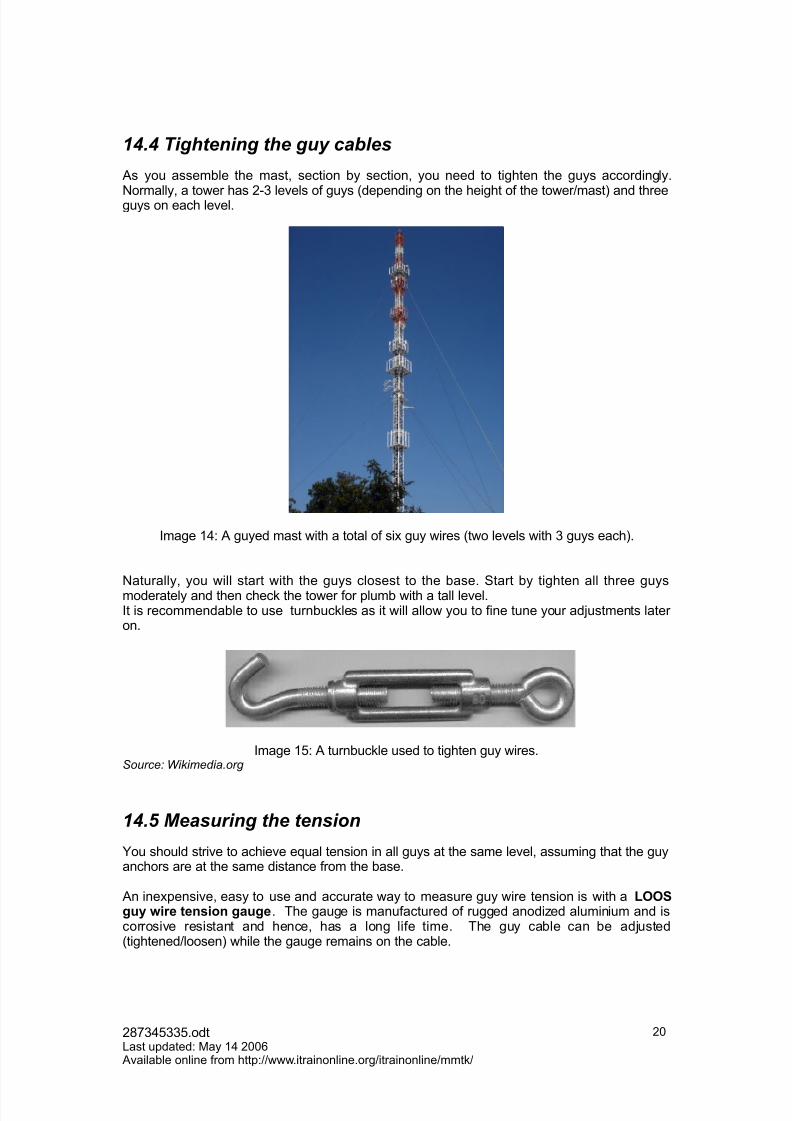
As you assemble the mast8 section by section8 you need to tighten the guys accordingly.
:ormally8 a tower has 2-3 leels of guys 6depending on the height of the towermast7 and threeguys on each leel.
Image 1! A guyed mast with a total of si guy wires 6two leels with 3 guys each7.
:aturally8 you will start with the guys closest to the base. $tart by tighten all three guysmoderately and then check the tower for plumb with a tall leel.It is recommendable to use turnbuckles as it will allow you to fine tune your adustments later on.
Image 1#! A turnbuckle used to tighten guy wires.Source" ikimedia)org
1$.5 Measuring the tension
Pou should strie to achiee e9ual tension in all guys at the same leel8 assuming that the guyanchors are at the same distance from the base.
An inepensie8 easy to use and accurate way to measure guy wire tension is with a LOO;/uy -)re te%s)o% /au/e. The gauge is manufactured of rugged anodi=ed aluminium and iscorrosie resistant and hence8 has a long life time. The guy cable can be adusted6tightenedloosen7 while the gauge remains on the cable.
2*(3#33#.odt0ast updated! "ay 1 2,,& Aailable online from http!www.itrainonline.orgitrainonlinemmtk
2,

7/17/2019 11 en Mmtk Wireless Communication-Tower Handout
http://slidepdf.com/reader/full/11-en-mmtk-wireless-communication-tower-handout 21/26
1$.! Measuring tower plum,
As you are tightening the guy wires and measuring the tension8 you need to measure how
plumb your tower is8 so that you do not end up with a tower in /i=a1 style.
A simple method to measure the plumb is to use a plumb bob. A plumb bob is a weight that isattached to a line. The line is suspended to the center of the tower at the first guy point. Theplumb bob will form an eact ertical line 6due to graity7 and the guys should be adusted sothat the tower is parallel with the bob line.
If the wind catches the line 6depending the weight of the bob and the wind conditions7 you canplace a bucket of water at the base of the tower to reduce the swinging of the bob.
Fhen the first tower section is plumb8 you continue to the net section.
Image 1&! A plumb bob used to adust the guys in order to ensure a ertical tower.
1 The top of the leaning tower in /i=a is about # m 61& ft7 from the ertical. An ecellenteample of a tower that is not plumb.
2*(3#33#.odt0ast updated! "ay 1 2,,& Aailable online from http!www.itrainonline.orgitrainonlinemmtk
21
<ENERAL TIP; 5OR <U? TEN;IONIN<
/ut a separate wire8 or one of the long loose ends8 through all theturnbuckles to preent them from loosening
0oop a cable through all of the thimbles 6in a circle7 in case one of theturnbuckles breaks.
The guy tension changes with temperature due to epansion andcontraction. That means8 if the initial tension was done in the winter8 it willloosen up in the summer due to epansion caused by higher temperature.

7/17/2019 11 en Mmtk Wireless Communication-Tower Handout
http://slidepdf.com/reader/full/11-en-mmtk-wireless-communication-tower-handout 22/26
1$.- "emporary guys
Fhen you are assembling you tower8 some of the tower sections 6most of them7 will not bee9uipped with guy wires since normally only two layers of guys are used. That means that you
will be working in tower sections that might be 2-3 tower sections aboe the last guy point."ost people seem to feel comfortable climbing two sections 6appro. &m7 aboe the last guypoint. "ore eperienced climbers might allow 3- tower sections aboe the last guy point untilthe sway becomes too great. The solution to this problem is to add temporary guys to tower sections placed between guy points. The temporary wires are remoed when the permanentguy wires are in place.
A good rule of thumb is to use temporary guys any time if you are 2 sections 62, feet &m7 or more aboe the last permanent guy set.
Temporary guys do not need to withstand the same load that permanent ones must. If youplan to finish all permanent guys the same day 6and the weather is fair78 you can allow fairlylight temporary guys. 'oweer8 if you can not compete the permanent guying in one day8 youshould go for more stable temporary guys.
The material of the temporary guys should hae a ery low stretch 6i.e. being stiff7 likelightweight steel cable or twisted polyester.
&0' Cl)*b)%/
It should not come as a surprise to you8 that climbing a 1#, feet tower is dangerous. Climbingtall structures re9uires ade9uate tra)%)%/ and e@u)p*e%t.
As a rule of the thumb8 a person with no climbing eperience8 should not climb a tower higher than heshe can surie after a possible fall to the ground.
The safest8 most comfortable8 and most ersatile type of climbing belt is a seat (ar%ess. If you are a professional tower climber8 you will need to follow 4$'A re9uirements for harnessand use a Hfall arrestB type of harness. This harness typically has a full body arrangement.
Image 1(! a7 $eat harness b7 A harness with fall arrest.
Source" 9l:tter oc ;gf<:ll. ttp"((www)klatterocogf<all)com '3mage 1=a*
Pou should be e9uipped with a belt around your waist with accessory loops for tool bucketsand carabiners.
2*(3#33#.odt0ast updated! "ay 1 2,,& Aailable online from http!www.itrainonline.orgitrainonlinemmtk
22

7/17/2019 11 en Mmtk Wireless Communication-Tower Handout
http://slidepdf.com/reader/full/11-en-mmtk-wireless-communication-tower-handout 23/26
4ther climbing e9uipment that is releant!• Climbing lanyards
• Carabiners• <opes
?inally8 you will need appropriate clothes for the mission including helmet8 shoes and gloes6do not forget to drinkQ7.
&#' L)/(te%)%/ protect)o%
0ightning protection is a must for any structure eleated aboe the surroundings. 0ightening isa common enemy to wireless installations in high structures and must be preented as far as
it can.There are generally speaking two different ways that lightening can damage your e9uipment8direct and indirect hits.
1!.1 Direct hits
Towers should be e9uipped with ?ranklin rods properly grounded at each foundation point.0egal re9uirements in most areas only re9uire grounding of the tower8 but guy-cable groundingis adised as well.
The mast top should be connected to the ground by a low resistance cable8 usually of copper or similar conductie material. $uitable ground clamps to attach the cable to the mast and theground system are needed. The cable must hae a good electrical connection8 so make surethat all paint and rust 6corrosion7 are remoed from the area where the clamp attaches to. Also8 use dielectric grease on the clamp connection to preent any electrolysis actiity due todissimilar metals.
'oweer8 if the lightening hits the tower itself 6or the e9uipment7 there is ery little that cansae it.
1!.2 *ndirect hits
Induction currents 6indirect hits7 through nearby lightning strike can cause damage to outdoor radio e9uipment. It can be preented by using surge protectors to ulnerable e9uipment and
choosing radios that hae a higher oltage rating. 'oweer8 surge protectors does not protectthe antenna8 only the radio.
2*(3#33#.odt0ast updated! "ay 1 2,,& Aailable online from http!www.itrainonline.orgitrainonlinemmtk
23
<ENERAL TIP; 5OR CLIM7IN< EUIPMENT
$tay away from leather belts which are no longer approed by 4$'A. Theleather can dry out and become seriously weakened.
"ake sure that the climbing gear that you are using is comfortable to wear for long periods as you will probable be up in the tower for many hours.
Do not be cheap when it comes to climbing e9uipment. A mistake can befatal and you hae only one life in this game. Also8 you will perform thework better if you feel safe and enoy the time up in the tower.
Try to keep all e9uipment as light as possible

7/17/2019 11 en Mmtk Wireless Communication-Tower Handout
http://slidepdf.com/reader/full/11-en-mmtk-wireless-communication-tower-handout 24/26
&1' Corros)o%
Corrosion is an attack on material though a chemical reaction with the enironment. "aterialsaffected by corrosion are not only metals but also for eample plastics. The enironment thatcan cause corrosion can be air 6oygen78 water and chemical substances.
Corrosion implies deterioration of useful properties in the material and is something you wantto aoid to all prices. A well-known case of corrosion is weakening of steel due to oidation of the iron atoms.
In fact8 corrosion is the tendency of a re$)%ed *etal to retur% to )ts %at)ve state.
There are certain conditions which must eist before a so called corros)o% cell can function.The following elements are needed!
1. Anode 6positie charged72. Cathode 6negatie charged73. >lectrical path 6between anode and cathode7. >lectrical conductie electrolyte
Image 1*! An actie corrosion cell
Source" 3T 46
The cause behind a corrosion cell is a pote%t)al 6oltage7 d)$$ere%ce between the anode andcathode. Fhen all four conditions 6see element 1- aboe7 are met8 an actie corrosion cell isin place.
Fhen the anode and cathode are electrically connected8 the anode is positiely charged andthe cathode is negatiely charged. Fhen corrosion takes place8 electrons moes from the
anode 6positie7 to the cathode 6negatie7. In the anode8 o4)dat)o% occurs while in thecathode8 a process called reduct)o% takes place.
4idation implies that electrons are emitted which has an detrimental affect on the anodewhich weakens the material. <eduction implies that the electrons are bound to the material.
4ften8 moist from rain or humid air will play the role as the electrolyte and cause corrosion. Also8 oygen can contribute to corrosion.
The impact of corrosion in guy anchors or re-bars can be etensie8 not only financially costlybut also cause fatal accidents with people inoled. The problem with corrosion can bepreented8 or at least greatly reduced8 by haing these risks in mind when establishing atower and using a suitable method for preenting corrosion.
Also8 careful maintenance of the tower within regular interals is important.
2*(3#33#.odt0ast updated! "ay 1 2,,& Aailable online from http!www.itrainonline.orgitrainonlinemmtk
2
7/17/2019 11 en Mmtk Wireless Communication-Tower Handout
http://slidepdf.com/reader/full/11-en-mmtk-wireless-communication-tower-handout 25/26
1-.1 Corrosion preention
In simple words8 corrosion in terms of tower constructions includes the eistence of thefollowing two elements!
• 4ygen 6or dis-similar metals7
• >lectrolyte 6a li9uid with free ions like water with minerals7
The corrosion preention mechanisms that eists8 targets these two elements.
&1'&'& A%t)o4)da%t Bo)%t co*pou%d
Corrosion can be preented by using an a%t)o4)da%t Bo)%t co*pou%d which can protect themetals from moisture An efficient antioidant has two components!
• ?inely diided metal particles 6=inc or copper7• A durable grease 6based on silicone or petroleum7
The grease will hold the metal particles and stick them to the metal surface and eclude bothoygen and moisture.
&1'&'+ Cat(od)c protect)o%
Corrosion can also be preented by the use of Cathodic protectionB. Cathodic protectionmakes use of the known process in a corrosion cell to effectiely aoid the negatie effects of corrosion.
%alanic anode protection is a simple method of cathodic protection which is based on theidea of a sacr)$)c)al a%ode. In the case of a preenting corrosion to a tower anchor8 asacrificial anode is electrically bonded to the anchor support.
The material of the anode must be higher on the galanic series 1 than the metal is shouldprotect. In that way8 the anode will corrode instead of the anchor or tower components 6thereof the name8 sacrificial7. A sacrificial anode is normally made of magnesium or =inc.
It is not only the material of the anode and cathode that matters for corrosion8 it is also arelationship between the si=es of the anode and the cathode that has an impact on theseerity of the corrosion cell.
• Fhen the area of the cat(ode is ery lar/e in relationship to that of the anode8 the
corros)o% cell will be more severe8 and thus the faster the anode will deteriorate.
• If the a%ode is ery lar/e in relationship to the cathode8 the effects of corrosion are
much less and the anode deterioration is more gradual.
$ince the purpose of the sacrificial anode is to be corroded8 it must be replaced after sometime.
$ee document @nderstanding and /reenting %uyed Tower ?ailure Due to Anchor $haftCorrosionB for further information about corrosion related to towers.
1In the galanic series8 each metal has his own placement 6a number7 according to thepotential it has to other metals.
2*(3#33#.odt0ast updated! "ay 1 2,,& Aailable online from http!www.itrainonline.orgitrainonlinemmtk
2#

7/17/2019 11 en Mmtk Wireless Communication-Tower Handout
http://slidepdf.com/reader/full/11-en-mmtk-wireless-communication-tower-handout 26/26
&2' Ma)%te%a%ce
The tower should be inspected at least twice per year. The inspection should 6at minimum7include the following!
R >nsure that all hardware is tight R >nsure proper tension in the guy cables R Inspect for corrosion. If corrosion is found8 remoe loose pieces and add paint.
&3' Co%clus)o%s
To establish a communication tower re9uires a great deal of planning8 access to eperiencedpersonnel and good tools. Fithout any of these components8 the tower will not stand up for along time.
A baseB of good 9uality is essential for the life time of a towermast. If the base in not done
with care8 fatal accidents can occur which might not ust turn out to be epensie but alsoinclude personal tragedies.
The TIA 6Telecommunications Industry Association7 has established a set of standards thatrelates to tower establishments!
• The Structural Standards for Steel Antenna Towers and Antenna Supporting
Structures 6A:$ITIA 222-?-1++&7B8 it proides a set of minimum criteria for specifyingand designing steel antenna towers and antenna supporting structures.
• “Structural Standards for Installation of Antenna and Antenna Supporting
Structures" TIA/,IAN+01" 2in oles%# it is another standard that
aims to improve the safety for tower wor&ers.
It is highly recommended to have a copy of these standards when planning for atower/mast structure.
The fie main issues to remember for this unit can be summari=ed as follows!
$. 3elect the type of tower depending on antenna load# footprint# heightneeded and financial budget.
). A base foundation of good quality is essential for a safe tower with long lifttime
(. 4or&ing at high height does always imply danger. 5o not be cheap when it
comes to security. 6se good equipment and play safe.
+. 7a&e sure that you have the time that you need. 3tress will allow you toma&e mista&es which can be very costly.
!. Always &eep in mind the ris&s of corrosion and prevent it as far as you can.Also plan for continuous inspections for corrosion and other defects.
2&


![07 en Mmtk Wireless Radio-link Handout[1]](https://static.fdocuments.net/doc/165x107/577d367c1a28ab3a6b933947/07-en-mmtk-wireless-radio-link-handout1.jpg)