10susp. Delantera y Manubrio suzuki intruder
37
CHAPTER TEN FRONT SUSPENSION AND STEERING This chapter describes repair and maintenance procedures for the front wheel, front forks and steer- ing components. Front suspension torque specifications are cov- ered in Table 1. Tables 1-3 are located at the end of this chapter. NOTE Where differences occur relating to the United Kingdom (U.K.) models they are identified. If there is no (U.K.) designa- tion relating to a procedure, photo or illustration it is identical to the United States (U.S.) models. FRONT WHEEL Removal NOTE The front brake disc is mounted on the left-hand side of the front wheel on 1985-1987 models (VS700) and mounted on the right-hand side of the front wheel on 1988-on models (VS750). This procedure is shown on a 1988 model. CAUTION Care must be taken when removing, handling and installing a wheel with a disc brake rotor. The rotor is relatively
Transcript of 10susp. Delantera y Manubrio suzuki intruder

CHAPTER TEN
FRONT SUSPENSION AND STEERING
This chapter describes repair and maintenance procedures for the front wheel, front forks and steer-ing components.
Front suspension torque specifications are cov-ered in Table 1. Tables 1-3 are located at the end of this chapter.
NOTE Where differences occur relating to the United Kingdom (U.K.) models they are identified. If there is no (U.K.) designa-tion relating to a procedure, photo or illustration it is identical to the United States (U.S.) models.
FRONT WHEEL
Removal
NOTE The front brake disc is mounted on the left-hand side of the front wheel on 1985-1987 models (VS700) and mounted on the right-hand side of the front wheel on 1988-on models (VS750). This procedure is shown on a 1988 model.
CAUTION Care must be taken when removing, handling and installing a wheel with a disc brake rotor. The rotor is relatively

thin in order to dissipate heat and to minimize unsprung weight. The rotor is designed to withstand tremendous rota-tional loads, but can be damaged when subjected to side impact loads. If the rotor is knocked out of true by a side impact, a pulsation will be felt in the front brake lever when braking. The ro-tor is too thin to be trued and must be replaced with a new one. Protect the rotor when transporting a wheel to a dealer or tire specialist for tire service. Do not place a wheel in a car trunk or pickup bed without protecting the rotor from side impact.
1. On 1987-on models, remove the front axle trim cap (Figure 1) from each fork leg. 2. On 1985 and 1986 models, remove the cotter pin and the front axle nut from the right-hand side. 3. Loosen the front axle pinch bolt (Figure 2). 4A. On 1987 models, loosen the front axle from the fork leg. 4B. On 1988-on models, loosen the front axle (Fig-ure 3) from the right-hand fork leg. 5. Place wood blocks under the footpeg assembly to support the bike securely with the front wheel off the ground. 6. Remove the speedometer cable (Figure 4) from the speedometer gear box. 7A. On 1985 and 1986 models, withdraw the front axle. 7B. On 1987-on models, completely unscrew the axle from the right- or left-hand fork leg and remove the axle. 8. Pull the wheel down and forward and remove the wheel from the front fork and the brake caliper.
NOTE Insert a piece of vinyl tubing or wood in the caliper in place of the brake disc. That way if the brake lever is inadver-tently squeezed, the piston will not be forced out of the cylinder. If this does happen, the caliper may have to be dis-assembled to reseat the piston and the system will have to be bled. By using the wood, bleeding the brake is not neces-sary when installing the wheel.
9. Remove the spacer (Figure 5) from the brake disc side of the hub.

10A. On 1985-1987 models, remove the spacer and speedometer gear box from the other side of the hub. 10B. On 1988-on models, remove the speedometer gear box from the other side of the hub.
CAUTION Do not set the wheel down on the disc surface as it may get scratched or warped. Set the sidewalls on 2 wood blocks (Figure 6).
Installation
1. Make sure the axle bearing surfaces of the fork sliders and axle are free from burrs and nicks. 2. Install the spacer (Figure 5) into the brake disc side of the hub. 3. Align the tangs of the speedometer drive gear (Figure 7) with the notches in the front hub and install the speedometer gear box. Make sure the gear box seats completely. If the speedometer compo nents do not mesh properly, the wheel hub compo nents will be too wide for installation. 4. On 1985-1987 models, install the spacer on top of the speedometer gear box. 5. Position the wheel, inserting the brake disc into the caliper carefully to prevent damage to the brake pads. 6. Apply a light coat of grease to the front axle. Insert the front axle through the fork leg, speedome ter gear box and the wheel hub. 7. Make sure that spacer (Figure 8) is still in place on the brake disc side of the wheel. 8A. On 1985 and 1986 models, install the front axle, then install the front axle nut, but do not tighten it. 8B. On 1987-on models, screw the axle into the right-or left-hand fork leg, but do not tighten it. 9. Slowly rotate the wheel and install the speedome ter cable into the speedometer housing (Figure 4). Position the speedometer housing and cable so that the cable does not have a sharp bend in it. 10. Tighten the front axle, or axle nut, to the torque specification listed in Table 1. 11. Remove the wood block(s) from under the foot- peg assembly. 12. With the front brake applied, push down hard on the handlebars and pump the forks several times to seat the front axle.

13. Tighten the front axle pinch bolt (Figure 2) to the torque specification listed in Table 1. 14. After the wheel is completely installed, rotate it several times to make sure that it rotates freely. Apply the front brake as many times as necessary to make sure all brake pads are against the brake disc correctly. 15. On 1987-on models, install the front axle trim cap (Figure 1) into each fork leg.
Inspection
1. Remove any corrosion from the front axle with a piece of fine emery cloth. Clean axle with solvent, then wipe the axle clean with a lint-free cloth. 2. Check axle runout. Place the axle on V-blocks and place the tip of a dial indicator in the middle of the axle (Figure 9). Rotate the axle and check runout. If the runout exceeds 0.25 mm (0.010 in.), replace the axle; do not attempt to straighten it. 3. Check rim runout as follows:
a. Remove the tire from the rim as described in this chapter.
b. Measure the radial (up and down) runout of the wheel rim with a dial indicator as shown at A, Figure 10. If runout exceeds 2.0 mm (0.08 in.), check the wheel bearings.
c. Measure the axial (side to side) runout of the wheel rim with a dial indicator as shown at B, Figure 10. If runout exceeds 2.0 mm (0.08 in.), check the wheel bearings.
d. If the wheel bearings are okay, wire wheels can be trued as described under Wire Wheel Spoke Adjustment in this chapter. Cast wheels cannot be serviced, but must be replaced.
e. Replace the front wheel bearings as described under Front Hub in this chapter.
4. Inspect the wheel rim (Figure 11) for dents, bending or cracks. Check the rim and rim sealing surface for scratches that are deeper than 0.5 mm (0.01 in.). If any of these conditions are present, replace the rim (wire wheels) or wheel (case wheels).
Speedometer Gear Box Inspection and Lubrication
NOTE The speedometer gear box is a sealed assembly and no replacement parts are

available. If any part of the gear box is defective the entire assembly must be replaced.
1. Remove the front wheel as described in this chapter. 2. Inspect the oil seal (A, Figure 12) for leakage. 3. Inspect the tangs (B, Figure 12) of the speedome ter drive gear for wear or damage. 4. Inspect the notches (Figure 13) in the front hub for wear or damage. Repair the hub or replace the wheel. 5. Install the front wheel as described in this chapter.
FRONT HUB
Inspection
Inspect each wheel bearing prior to removing it from the wheel hub.
CAUTION Do not remove the wheel bearings for inspection purposes as they will be damaged during the removal process. Remove wheel bearings only if they are to be replaced.
1. Perform Steps 1-4 of Disassembly in the follow ing procedure. 2. Turn each bearing by hand. Make sure bearings turn smoothly. 3. Inspect the play of the inner race (Figure 14) of each wheel bearing. Check for excessive axial play (A, Figure 15) and radial play (B, Figure 15). Replace the bearing if it has an excess amount of free play. 4. On non-sealed bearings, check the balls for evi dence of wear, pitting or excessive heat (bluish tint). Replace the bearings if necessary; always replace as a complete set. When replacing the bearings, be sure to take your old bearings along to ensure a perfect matchup.
NOTE Fully sealed bearings are available from many bearing specialty shops. Fully sealed bearings provide better protection from dirt and moisture that may get into the hub.

Disassembly
Refer to the following illustrations for this proce-dure:
a. Figure 16: wire wheel. b. Figure 17: cast wheel.
1. Remove the front wheel as described in this chap ter. 2. Remove the spacer (Figure 5) from the brake disc side of the hub. 3A. On 1985-1987 models, remove the spacer and speedometer gear box from the other side of the hub. 3B. On 1988-on models, remove the speedometer gear box (Figure 18) from the other side of the hub. 4. If necessary, remove the bolts (Figure 19) secur ing the brake disc and remove the disc. 5. Before proceeding further, inspect the wheel bearings as described in this chapter. If they must be replaced, proceed as follows.
6. To remove the right- and left-hand bearings and distance collar, insert a soft aluminum or brass drift into one side of the hub. 7. Push the distance collar over to one side and place the drift on the inner race of the lower bearing. 8. Tap the bearing out of the hub with a hammer, working around the perimeter of the inner race. 9. Repeat for the bearing on the other side. 10. Clean the inside and the outside of the hub with solvent. Dry with compressed air.
Assembly
1. On non-sealed bearings, pack the bearings with a good quality bearing grease. Work the grease in between the balls thoroughly; turn the bearing by hand a couple of times to make sure the grease is distributed evenly inside the bearing.
FRONT WIRE WHEEL
1. Trim cap 8. Wheel rim and hub 2. Spacer 9. Distance collar 3. Bolt 10. Bearing 4. Brake disc 11. Speedometer gear 5. Bearing 12. Front axle 6. Inner tube 13. Trim cap 7. Tire
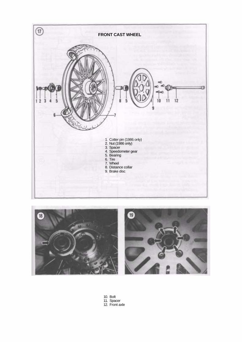
FRONT CAST WHEEL
1. Cotter pin (1986 only)2. Nut (1986 only) 3. Spacer 4. Speedometer gear 5. Bearing 6. Tire 7. Wheel 8. Distance collar 9. Brake disc
10. Bolt11. Spacer 12. Front axle

2. Blow any dirt or foreign matter out of the hub prior to installing the bearings.
CAUTION Install non-sealed bearings with the sin-gle sealed side facing outward. Tap the bearings squarely into place and tap on the outer race only. Do not tap on the inner race or the bearing might be dam-aged. Be sure that the bearings are com-pletely seated.
3A. A special Suzuki tool set-up (Suzuki part No. 09924-84510) can be used to install the wheel bear-ings as follows:
a. Install the right-hand bearing into the hub first.
b. Set the bearing with the sealed side facing out and install the bearing installer as shown in Figure 20.
c. Tighten the bearing installer (Figure 21) and pull the right-hand bearing into the hub until it is completely seated. Remove the bearing in staller.
d. Turn the wheel over (right-hand side up) on the workbench and install the distance collar.
e. Set the left-hand bearing with the sealed side facing out and install the bearing installer as shown in Figure 22.
NOTE Suzuki does not specify what "a slight clearance" is equivalent to. The impor-tant thing is that the 2 parts are not-pressed up against each other.
f. Tighten the bearing installer and pull the left- hand bearing into the hub until there is a slight clearance between the inner race and the dis tance collar.
g. Remove the bearing installer. 3B. If special tools are not used, perform the follow-ing:
a. Tap the right-hand bearing squarely into place and tap on the outer race only. Use a socket (Figure 23) that matches the outer race diame ter. Do not tap on the inner race or the bearing might be damaged. Be sure that the bearing is completely seated (Figure 14).
b. Turn the wheel over (right-hand side up) on the workbench and install the distance collar.

c. Use the same tool set-up and drive in the left-hand bearing.
4. If the brake disc was removed, perform the fol lowing:
a. Apply red Loctite (No. 271) to the brake disc bolts prior to installation.
b. Install the brake disc and bolts (Figure 19). Tighten to the torque specifications listed in Table 1.
5. Install the spacer (Figure 5) into the brake disc side of the hub. 6. Align the tangs of the speedometer drive gear (Figure 7) with the notches in the front hub and install the speedometer gear box. Make sure the gear box seats completely. If the speedometer compo-
nents do not mesh properly the hub components of the wheel will be too wide for installation. 7. On 1985-1987 models, install the spacer on top of the speedometer gear box. 8. Install the front wheel as described in this chapter.
WHEELS
Wheel Balance
An unbalanced wheel is unsafe. Depending on the degree of unbalance and the speed of the motorcycle, the rider may experience anything from a mild vi-bration to a violent shimmy which may even result in loss of control.
The weights are attached to the wheel spokes or to the rim on cast wheels. Weight kits are available from motorcycle dealers. Before you attempt to balance the wheel, check to be sure that the wheel bearings are in good condition and properly lubri-cated. The wheel must rotate freely.
NOTE When balancing the wheels do so with the brake disc attached. The brake disc rotates with the wheel and will affect the balance.
1. Remove the wheel as described in this chapter or Chapter Ten. 2. Mount the wheel on a fixture such as the one shown in Figure 24 so it can rotate freely. 3. Give the wheel a spin and let it coast to a stop. Mark the tire at the lowest point (Figure 25). 4. Spin the wheel several more times. If the wheel keeps coming to rest at the same point, it is out of balance. 5A. On cast wheels, tape a test weight to the upper (or light) side of the wheel. 5B. On wire wheels, attach a test weight to the upper (or light) side of the wheel at the spoke or tape a test weight (Figure 26) to the rim. 6. Experiment with different weights until the wheel, when spun, comes to a rest at a different position each time. 7. Remove the test weight and install the correct size weight.

Wire Wheel Spoke Adjustment
TIRES
Tire Safety
Spokes loosen with use and should be checked periodically. If all appear loose, tighten all spokes on one side of the hub, then tighten all spokes on the other side with a spoke wrench. One-half to one turn should be sufficient; do not overtighten.
After tightening the spokes, check the rim runout to make sure you haven't pulled the rim out of shape. One way to check rim runout is to mount a dial indicator to the front fork or swing arm so that it bears on the rim.
If you don't have a dial indicator, fabricate the tester shown in Figure 27. Adjust the position of the bolt until it just clears the wheel rim. Rotate the wheel and note whether the clearance between the bolt and the rim increases or decreases. Mark the tire with chalk or crayon in areas that produce signifi-cantly large or small clearances. Clearance must not change by more than 2 mm (0.08 in.).
To pull the rim out, tighten the spokes which terminates on the same side of the hub (Figure 28). In most cases, only a small amount of adjustment is necessary to true a rim. After adjustment, rotate the wheel and make sure another area has not been pulled out of true. Continue adjusting and checking until the runout does not exceed 2 mm (0.08 in.).
After installing new tires on the bike, break them in correctly. Remember that a new tire has relatively poor adhesion to the road surface until it is broken in properly. Don't subject a new tire to any high speed riding for at least the first 60 miles (100 km).
Even after the tires are broken in properly, always warm them up prior to the first ride of the day. This will lessen the possibility of loss of control of the bike. If you have purchased a tire brand other than those originally installed by the factory, maintain the correct tire inflation pressure recommended by that tire manufacturer and not those listed in Table 2 located in Chapter Three. Table 2 is for original equipment tires only.
1. Bracket to fit fender brace 2. Wheel rim 3. Nuts 4. Bolt

Tubeless Tires (Cast Wheels Only)
WARNING Do not install an inner tube inside a tubeless tire. The tube will cause an abnormal heat buildup in the tire.
Tubeless tires have the word "TUBELESS" molded into the tire sidewall and the rims have "SUITABLE FOR TUBELESS TIRES," "TUBELESS TIRE AP-PLICABLE," or equivalent cast into them.
NOTE Tube type tires have the word "TUBE TYPE" (Figure 29) molded into the tire.
When a tubeless tire is flat, it should be removed from the rim to inspect the inside of the tire and to apply a combination plug/patch from the inside. Don't rely on a plug or cord repair applied from outside the tire. They might be okay on a car, but they're too dangerous on a motorcycle.
After repairing a tubeless tire, don't exceed 50 mph (80 kph) for the first 24 hours. Never race on a repaired tubeless tire. The patch could work loose from tire flexing and heat.
TIRE CHANGING
The wheels can easily be damaged during tire removal. Special care must be taken with tire irons when changing a tire to avoid scratches and gouges to the outer rim surface. Insert scraps of leather between the tire iron and the rim to protect the rim from damage. The stock wire wheels are designed for use with tube type tires while the stock cast wheels are designed for use with tubeless tires.
When removing a tubeless tire, take care not to damage the tire beads, inner liner of the tire or the wheel rim flange. Use tire levers or flat handled tire irons with rounded ends.
NOTE This procedure applies to both tube type and tubeless tires. Where differences oc-cur regarding inner tube removal and installation they are identified.
Removal
1. If you are going to reinstall the existing tire, mark the valve stem location on the tire (Figure 30) so the tire can be installed in the same position for easier balancing. 2. Remove the valve stem core to deflate the tire. On tube type tires, unscrew the locknut (Figure 31) from the valve stem.

NOTE Removal of tubeless tires from their rims can be very difficult because of the exceptionally tight bead/rim seal. Breaking the bead seal may require the use a special tool (Figure 32). If you are unable to break the seal loose, take the wheel to a motorcycle dealer and have them break it loose.
CAUTION The inner rim and tire bead area are sealing surfaces on the tubeless tire. Do not scratch the inside of the rim or dam-age the tire bead as this will result in an air leak.
3. Press the entire bead on both sides of the tire into the center of the rim. Make sure the tire is broken loose around the entire perimeter of the wheel. 4. Lubricate the beads with soapy water.
CAUTION Use rim protectors or insert scraps of leather between the tire irons and the rim to protect the rim from damage.
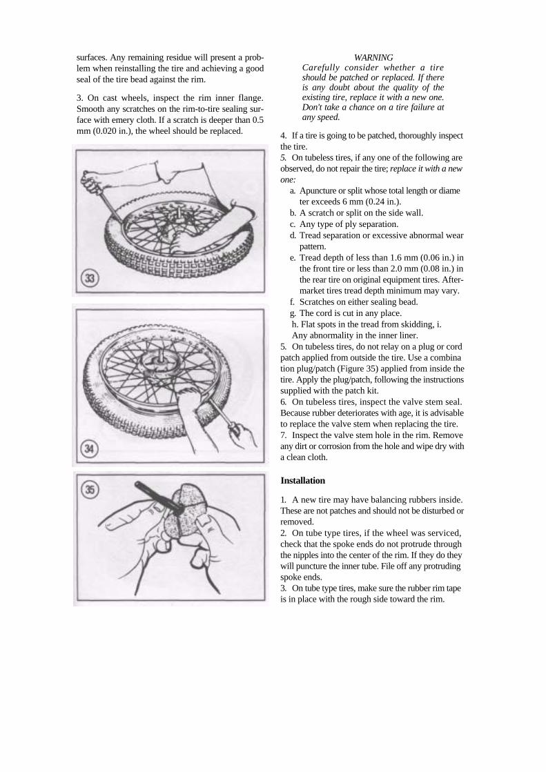
5. Insert the tire iron under the bead next to the valve (Figure 33). Force the bead on the opposite side of the tire into the center of the rim and pry the bead over the rim with the tire iron. 6. Insert a second tire iron next to the first to hold the bead over the rim. Then work around the tire with the first tire iron, prying the bead over the rim. On tube type tires, be careful not to pinch the inner tube with the tire irons. 7. On tube type tires, remove the valve from the hole in the rim and remove the inner tube from the tire.
NOTE On tube type tires, Step 8 is only neces-sary to completely remove the tire from the rim, as in tire replacement. On tube-less tires, it is necessary to remove the tire for repair work.
8. Stand the tire on end or turn it over. Insert the tire iron between the second bead and the side of the rim that the first bead was pried over (Figure 34). Force the bead on the opposite side from the tire iron into the center of the rim. Pry the second bead off the rim, working around as with the first. Remove the tire from the rim. 9. Inspect the rim as described in this chapter.
Tire and Rim Inspection
1. Wipe off the inner surfaces of the wheel rim. Clean off any rubber residue or any oxidation. 2. On tubeless tires, if a can of pressurized tire sealant was used for a temporary fix of a flat, thor oughly clean off all sealant residue from the rim
surfaces. Any remaining residue will present a prob-lem when reinstalling the tire and achieving a good seal of the tire bead against the rim.
3. On cast wheels, inspect the rim inner flange. Smooth any scratches on the rim-to-tire sealing sur-face with emery cloth. If a scratch is deeper than 0.5 mm (0.020 in.), the wheel should be replaced.
WARNING Carefully consider whether a tire should be patched or replaced. If there is any doubt about the quality of the existing tire, replace it with a new one. Don't take a chance on a tire failure at any speed.
4. If a tire is going to be patched, thoroughly inspect the tire. 5. On tubeless tires, if any one of the following are observed, do not repair the tire; replace it with a new one:
a. Apuncture or split whose total length or diame ter exceeds 6 mm (0.24 in.).
b. A scratch or split on the side wall. c. Any type of ply separation. d. Tread separation or excessive abnormal wear
pattern. e. Tread depth of less than 1.6 mm (0.06 in.) in
the front tire or less than 2.0 mm (0.08 in.) in the rear tire on original equipment tires. After- market tires tread depth minimum may vary.
f. Scratches on either sealing bead. g. The cord is cut in any place. h. Flat spots in the tread from skidding, i. Any abnormality in the inner liner.
5. On tubeless tires, do not relay on a plug or cord patch applied from outside the tire. Use a combina tion plug/patch (Figure 35) applied from inside the tire. Apply the plug/patch, following the instructions supplied with the patch kit. 6. On tubeless tires, inspect the valve stem seal. Because rubber deteriorates with age, it is advisable to replace the valve stem when replacing the tire. 7. Inspect the valve stem hole in the rim. Remove any dirt or corrosion from the hole and wipe dry with a clean cloth.
Installation
1. A new tire may have balancing rubbers inside. These are not patches and should not be disturbed or removed. 2. On tube type tires, if the wheel was serviced, check that the spoke ends do not protrude through the nipples into the center of the rim. If they do they will puncture the inner tube. File off any protruding spoke ends. 3. On tube type tires, make sure the rubber rim tape is in place with the rough side toward the rim.

4A. On tube type tires, install the tube valve stem core into the tube valve. Place the tube into the tire and inflate it just enough to round it out. Too much air will make installing the tire difficult and too little air will increase the chances of pinching the tube with the tire irons.
NOTE Step 4B relates to metal valve steins on tubeless tire only.
4B. On tubeless tires, install a new valve stem as follows:
a. Insert the new valve stem into the rim. b. Install the nut and tighten with your fingers
only. Do not use pliers and overtighten the nut as it may distort the rubber sealing grommet that could result in an air leak.
c. Hold onto the nut and install and tighten the locknut securely.
d. Inspect the valve stem core rubber seal for hardness or deterioration. Replace the valve stem core if necessary.
5. If the tire was completely removed, lubricate both beads of the tire with soapy water. If only one side was removed, lubricate the exposed rim bead. 6. When installing the tire onto the rim make sure the correct tire, either front or rear is installed onto the correct wheel and also that the direction arrow (Figure 36) faces the direction of wheel rotation. 7. If remounting the old tire, align the mark made in Step 1, Removal with the valve stem. If a new tire is being installed, align the colored spot near the bead (indicating a lighter point on the tire) with the valve stem. 8. If the tire was completely removed from the rim, place the backside of the tire into the center of the rim (Figure 37). The lower bead should go into the center of the rim and the upper bead outside. Work around the tire in both directions (Figure 38). Use a tire iron for the last few inches of bead (Figure 39). 9. Press the upper bead into the rim opposite the valve stem. Pry the bead into the rim on both sides of the initial point with a tire iron, working around the rim to the valve (Figure 40). 10. On tube type tires, wiggle the valve stem to be sure the tube is not trapped under the tire bead. Set the valve squarely in the rim hole before screwing on the valve stem nut.
11. Check the bead on both sides of the tire for even fit around the rim.
12. Bounce the wheel several times, rotating it each time. This will force the tire beads against the rim flanges. After the tire beads are in contact with the rim evenly, inflate the tire to seat the beads. 13. On tubeless tires, place an inflatable band around the circumference of the tire. Slowly inflate the band until the tire beads are pressed against the
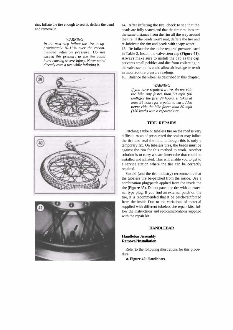
rim. Inflate the tire enough to seat it, deflate the band and remove it.
WARNING In the next step inflate the tire to ap-proximately 10-15% over the recom-mended inflation pressure. Do not exceed this pressure as the tire could burst causing severe injury. Never stand directly over a tire while inflating it.
14. After inflating the tire, check to see that the beads are fully seated and that the tire rim lines are the same distance from the rim all the way around the tire. If the beads won't seat, deflate the tire and re-lubricate the rim and beads with soapy water. 15. Re-inflate the tire to the required pressure listed in Table 2. Install the valve stem cap (Figure 41). Always make sure to install the cap as the cap prevents small pebbles and dirt from collecting in the valve stem; this could allow air leakage or result in incorrect tire pressure readings. 16. Balance the wheel as described in this chapter.
WARNING If you have repaired a tire, do not ride the bike any faster than 50 mph (80 kmlh)for the first 24 hours. It takes at least 24 hours for a patch to cure. Also never ride the bike faster than 80 mph (130 km/h) with a repaired tire.
TIRE REPAIRS
Patching a tube or tubeless tire on the road is very difficult. Acan of pressurized tire sealant may inflate the tire and seal the hole, although this is only a temporary fix. On tubeless tires, the beads must be against the rim for this method to work. Another solution is to carry a spare inner tube that could be installed and inflated. This will enable you to get to a service station where the tire can be correctly repaired.
Suzuki (and the tire industry) recommends that the tubeless tire be-patched from the inside. Use a combination plug/patch applied from the inside the tire (Figure 35). Do not patch the tire with an exter-nal type plug. If you find an external patch on the tire, it is recommended that it be patch-reinforced from the inside Due to the variations of material supplied with different tubeless tire repair kits, fol-low the instructions and recommendations supplied with the repair kit.
HANDLEBAR
Handlebar Assembly Removal/Installation
Refer to the following illustrations for this proce-dure:
a. Figure 42: Handlebars.

b. Figure 43: Steering stem (1985-1987). c. Figure 44: Steering stem (1988-on).
NOTE If it is not necessary to remove the com-ponents from the handlebar for service, perform this procedure. If component removal is necessary, refer to the Disas-sembly/Assembly in the following pro-cedure.
1. Remove the fuel tank as described under Fuel tank Removal/Installation in Chapter Seven. 2. Disconnect the brake light switch electrical con nector from the brake lever. 3. Disconnect the starter interlock switch electrical connector from the clutch lever.
CAUTION Cover the surrounding area with a heavy cloth or plastic tarp to protect it from accidental spilling of clutch and brake fluid. Wash any spilled clutch or brake fluid off any painted or plated surface immediately, as it will destroy the finish. Use soapy water and rinse thoroughly.
4. Remove the trim cap (Figure 45) from the Allen bolts. 5. Remove the Allen bolts (Figure 46) securing the handlebar upper holders.
6. Remove the upper holders and the handlebar assembly.
7. Move the handlebar assembly back and rest it on the frame. 8. Secure the handlebar assembly so the clutch and brake master cylinder reservoirs remain in the up right position. This is to minimize loss of hydraulic fluid and to keep air from entering into the clutch and brake system. It is not necessary to remove either hydraulic line. 9. Install by revering these removal steps, noting the following:
a. Tighten the Allen bolts to the torque specifica tion listed in Table 1. Tighten the front bolts first then the rear so there is a slight gap at the rear between the handlebar upper and lower holders (Figure 47).
b. Check the throttle operation. If necessary, ad just the throttle operation as described in Chap ter Three.
WARNING After installation is completed, make sure the brake lever does not come in contact with the throttle grip assembly when it is pulled on fully. If it does the brake fluid may be low in the reservoir; refill as necessary. Refer to Front Disc Brakes in Chapter Eleven.
HANDLEBARS
1992-ON
1. Flat handlebar 5. Washer 9. Balancer 2. Riser handlebar 6. Spacer 10. Cap 3. Nut 7. Expander 11. Bolt 4. Expander 8. Spacer

STEERING STEM (1985-1987)
1. Trim cap 2. Allen bolt 3. Handlebar upper holder 4. Allen bolt 5. Handlebar lower holder 6. Extension 7. Extension 8. Upper rubber cushion 9. Spacer
10. Lower rubber cushion 11. Clamp 12. Washer 13. Nut 14. Cotter pin 15. Trim cap 16. Allen bolt 17. Steering stem cap nut 18. Washer 19. Upper fork bridge 20. Steering stem nut 21. Dust seal 22. Upper bearing 23. Lower bearing 24. Steering stem

STEERING STEM (1988-ON)
1. Trim cap 2. Allen bolt 3. Handlebar upper holder 4. Allen bolt 5. Handlebar lower holder 6. Upper rubber cushion 7. Lower rubber cushion 8. Washer 9. Nut
10. Cotter pin 11. Trim cap 12. Allen bolt 13. Steering stem cap nut 14. Washer 15. Upper fork bridge 16. Steering stem nut 17. Dust seal 18. Upper bearing 19. Lower bearing 20. Steering stem

Handlebar and Component Removal/Installation
Refer to the following illustrations for this proce-dure:
a. Figure 42: Handlebars. b. Figure 43: Steering stem (1985-1987). c. Figure 44: Steering stem (1988-on).
NOTE If it is necessary to remove the compo-nents from the handlebar for service, perform this procedure. If component removal is not necessary, only the re-moval of the handlebar assembly; refer to the preceding procedure.
Right-hand side of handlebar
1. Remove the screws securing the right-hand handlebar switch assembly (Figure 48) together. 2. Partially remove the upper half and disconnect the throttle cable from the throttle assembly. Care fully lay the throttle cable over the fender or back over the frame. Be careful that the cable does not get crimped or damaged. 3. Remove the screw (Figure 49) securing the en gine stop switch electrical connector to the switch assembly. 4. Disconnect the brakelight switch electrical con nector (A, Figure 50) from the brake switch. 5. Remove the lower half of the right-hand switch assembly (B, Figure 50) from the handlebar. 6. Unscrew the rear view mirror (C, Figure 50) from the master cylinder.
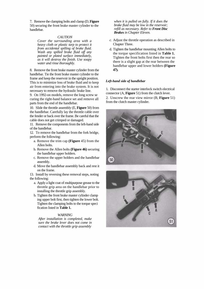
7. Remove the clamping bolts and clamp (D, Figure 50) securing the front brake master cylinder to the handlebar.
CAUTION Cover the surrounding area with a heavy cloth or plastic tarp to protect it from accidental spilling of brake fluid. Wash any spilled brake fluid off any painted or plated surface immediately, as it will destroy the finish. Use soapy water and rinse thoroughly.
8. Remove the front brake master cylinder from the handlebar. Tie the front brake master cylinder to the frame and keep the reservoir in the upright position. This is to minimize loss of brake fluid and to keep air from entering into the brake system. It is not necessary to remove the hydraulic brake line. 9. On 1992-on models, remove the long screw se curing the right-hand balance set and remove all parts from the end of the handlebar.
10. Slide the throttle assembly (E, Figure 50) from the handlebar. Carefully lay the throttle cable over the fender or back over the frame. Be careful that the cable does not get crimped or damaged. 11. Remove the components from the left-hand side of the handlebar. 12. To remove the handlebar from the fork bridge, perform the following:
a. Remove the trim cap (Figure 45) from the Allen bolts.
b. Remove the Allen bolts (Figure 46) securing the handlebar upper holders.
c. Remove the upper holders and the handlebar assembly.
d. Move the handlebar assembly back and rest it on the frame.
13. Install by reversing these removal steps, noting the following:
a. Apply a light coat of multipurpose grease to the throttle grip area on the handlebar prior to installing the throttle grip assembly.
b. Tighten the front brake master cylinder clamp ing upper bolt first, then tighten the lower bolt. Tighten the clamping bolts to the torque speci fication listed in Table 1.
WARNING After installation is completed, make sure the brake lever does not come in contact with the throttle grip assembly
when it is pulled on fully. If it does the brake fluid may be low in the reservoir; refill as necessary. Refer to Front Disc Brakes in Chapter Eleven.
c. Adjust the throttle operation as described in Chapter Three.
d. Tighten the handlebar mounting Allen bolts to the torque specification listed in Table 1. Tighten the front bolts first then the rear so there is a slight gap at the rear between the handlebar upper and lower holders (Figure 47).
Left-hand side of handlebar
1. Disconnect the starter interlock switch electrical connector (A, Figure 51) from the clutch lever. 2. Unscrew the rear view mirror (B, Figure 51) from the clutch master cylinder.

3. Remove the screws securing the left-hand handlebar switch assembly (C, Figure 51) together and remove the upper half of the switch. 4. Disconnect the all switch electrical connectors from the left-hand switch assembly. Remove the lower half of the switch from the handlebar. 5. Remove the clamping bolts and clamp (D, Figure 51) securing the clutch master cylinder to the handle bar.
CAUTION Cover the surrounding area with a heavy cloth or plastic tarp to protect it from accidental spilling of hydraulic fluid. Wash any spilled brake fluid off any painted or plated surface immedi-ately, as it will destroy the finish. Use soapy water and rinse thoroughly.
6. Remove the clutch master cylinder from the handlebar. Tie the master cylinder to the frame and keep the reservoir in the upright position. This is to minimize loss of hydraulic fluid and to keep air from entering into the clutch system. It is not necessary to remove the hydraulic brake line. 7. On 1992-on models, remove the long screw se curing the right-hand balance set and remove all parts from the end of the handlebar. 8. Slide the hand grip assembly (E, Figure 51) from the handlebar. 9. Remove the components from the right-hand side of the handlebar. 10. To remove the handlebar from the fork bridge, perform the following:
a. Remove the trim cap (Figure 45) from the Allen bolts.
b. Remove the Allen bolts (Figure 46) securing the handlebar upper holders.
c. Remove the upper holders and the handlebar assembly.
d. Move the handlebar assembly back and rest it on the frame.
11. Install by reversing these removal steps, noting the following:
a. Tighten the clutch master cylinder clamping upper bolt first, then tighten the lower bolt. Tighten the clamping bolts to the torque speci fication listed in Table 1.
b. Tighten all mounting bolts to the torque speci fication listed in Table 1.
STEERING HEAD AND STEM
Disassembly
Refer to the following illustrations for this proce-dure:
a. Figure 43: Steering stem (1985-1987). b. Figure 44: Steering stem (1988-on).
1. Remove the front wheel as described in this chapter. 2. Remove the handlebar assembly (A, Figure 52) as described in this chapter. 3. Remove the front forks as described in this chap- j ter. 4. Disconnect the electrical connector from the horn, headlight, speedometer and indicator light as sembly. 5. Remove the headlight assembly (B, Figure 52) as described under Headlight Housing Removal/In stallation in Chapter Eight. 6A. On 1985-1987 models, remove the clamping screws and disconnect the front brake and clutch master cylinder hydraulic hoses from (C, Figure 52) the lower fork bridge. 6B. On 1988-on models, perform the following:
a. Remove the union bolt and disconnect the hydraulic brake line from both the front brake master cylinder and clutch master cyl inder.
b. Carefully withdraw the hydraulic hoses (C, Figure 52) through the holes in both the upper and lower fork bridges. Cover the end of the hoses with a reclosable plastic bag and tie the loose end up to the frame.

8. Loosen the steering stem nut 1/4 turn (Figure 56), then retighten so that no play can be detected in the steering stem.
9. Move the steering stem back and forth from side-to-side (Figure 57). The steering stem should move freely from side-to-side with no looseness or stiffness. If necessary, repeat Step 6 and Step 8 and readjust the steering stem nut. 10. Install the upper fork bridge (B, Figure 53).
11. Install the washer and the steering stem cap nut (A, Figure 53). Tighten the cap nut only finger-tight at this time.
NOTE Steps 12-15 must be performed in this order to assure proper upper and lower fork bridge to fork alignment.
12. Temporarily slide the fork tubes into position until they bottom out in the stops in the upper fork bridge. 13. Temporarily install the front axle into the fork legs (Figure 58) and tighten securely. 14. Tighten the lower fork bridge bolts to the torque specification listed in Table 1. 15. Tighten the steering stem cap nut to the torque specification listed in Table 1. 16. Remove the front axle, loosen the lower fork bridge bolts and slide the front fork tubes down and out. 17A. On 1985-1987 models, reposition the front brake and clutch master cylinder hydraulic hoses (C, Figure 52) onto the lower fork bridge and install the clamps and screws. Tighten the screws securely. 17B. On 1988-on models, perform the following:
a. Remove the reclosable plastic bag from the loose end of the front brake and clutch hoses.
b. Carefully insert the hydraulic hoses (C, Figure 52) through the holes and rubber grommets in both the upper and lower fork bridges.
c. Attach the hydraulic brake line onto both the front brake master cylinder and clutch master cylinder. Refer to Chapter Five (Clutch) and Chapter Twelve (Brakes) for the correct proce dure for reattaching the hydraulic hoses, then bleed the systems as described in the appropri ate chapters.
18. Install the headlight assembly as described in Chapter Eight. 19. Reconnect the electrical connector to the horn, headlight, speedometer and indicator light assembly. 20. Install the front forks as described in this chap ter. 21. Install the handlebar assembly (A, Figure 52) as described in this chapter. 22. Install the front wheel as described in this chap ter.

STEERING HEAD BEARING RACES
The headset and steering stem bearing races are pressed into the headset portion of the frame. The races are easily bent, so they should not be removed unless they require replacement.
Headset Bearing Race Removal/Installation
1. Remove the steering stem as described in this chapter. 2A. A special Suzuki tool set-up (Suzuki bearing outer race remover part No. 09941-54911, steering bearing remover/installer part No. 09941-74910) can be used to remove the headset bearing race as follows:
a. Install the outer race remover (A, Figure 59) into one of the outer races.
b. Insert the bearing remover (B, Figure 59) into the backside of the outer race remover.
c. Tap on the end of the bearing remover with a hammer (C, Figure 59) and drive the bearing outer race out of the steering head. Remove the special tool from the outer race.
d. Repeat for the bearing outer race at the other end of the headset.
2B. If the special tools are not used, perform the following:
a. Insert a hardwood stick or soft punch into the head tube and carefully tap the outer race out from the inside (Figure 60).
b. After it is started, work around the outer race in a crisscross pattern so that neither the race nor the head tube is damaged.
3A. A special Suzuki tool set-up (Suzuki bearing installer part No. 09941-34513) can be used to install the headset bearing race as follows:
a. Position the outer races into the headset and just start them into position lightly with a soft- faced mallet. Just tap them in enough to hold them in place until the special tool can be installed.
b. Position the bearing installer (Figure 61) into both of the outer races.
c. Tighten the nuts on the bearing installer and pull the outer races into place in the headset. Tighten the nuts until both bearing outer races are completely seated in the head set and is flush with the steering head surface.
d. Remove the special tool. 3B. If the special tools are not used, perform the following:
a. Position one of the outer races into the headset and just start it into position lightly with a soft-faced mallet. Just tap it in enough to hold it in place.
b. Tap the outer race in slowly with a block of wood, a suitable size socket or piece of pipe (Figure 62). Make sure that the race is squarely

seated in the headset race bore before tapping it into place. Tap the race in until it is flush with the steering head surface, c. Repeat for the other outer race.
Steering Stem Lower Bearing Removal/Installation
1. Install the Suzuki special tool (bearing remover part No. 09941-84510) (A, Figure 63) onto the steering stem assembly (B, Figure 63). 2. Tighten the upper bolt (C, Figure 63) and with draw the lower bearing from the steering stem. 3. Remove the special tool and the lower bearing from the steering stem. 4. Install the lower bearing on the steering stem and slide it down onto the top of the shoulder at the base of the steering stem. 5. Install the Suzuki special tool (steering stem bearing installer, part No. 09941-74910) (A, Figure 64) on top of the lower bearing (B, Figure 64).

6. Using a hammer (C, Figure 64), carefully tap on the bearing installer and drive the lower bearing into place. 7. Remove the bearing installer. 8. Make sure it is seated squarely and is all the way down.
FRONT FORKS
Front Fork Service
Before suspecting major trouble, drain the front fork oil and refill with the proper type and quantity fork oil; refer to Front Fork Oil Change in Chapter Three. If you still have trouble, such as poor damp-ing, a tendency to bottom or top out or leakage around the rubber seals, follow the service proce-dures in this section.
To simplify fork service and to prevent the mixing of parts, the legs should be removed, serviced and installed individually.
Removal/Installation
1. Remove the fork cap bolt (Figure 65) and on 1987-on models, the spacer from the top of the fork tube.
NOTE Insert a piece of vinyl tubing or wood in the caliper in place of the brake disc. That way if the brake lever is inadver-tently squeezed, the piston will not be forced out of the cylinder. If this does happen, the caliper may have to be dis-assembled to reseat the piston and the system will have to be bled. By using the wood, bleeding the brake is not neces-sary when installing the wheel.
2. Remove the brake caliper as follows: a. Loosen, then remove the bolts (A, Figure 66)
securing the brake caliper assembly to the front fork.
b. Remove the caliper assembly (B, Figure 66) from the brake disc.
3. Remove the front wheel (C, Figure 66) as de scribed in this chapter. 4. Remove the screws securing the front fender to the front forks.
NOTE The Allen bolt at the base of the slider has been secured with a thread locking agent and is often very difficult to re-move because the damper rod will turn inside the slider. It sometimes can be removed with an air impact driver. If you are unable to remove it, take the fork tubes to a dealer and have the bolts removed.
5. If the fork assembly is going to be disassembled, slightly loosen (just break it loose) the Allen bolt at the base of the slider, using an Allen wrench. If the bolt is loosened too much, fork oil may start to drain out of the slider. 6. Remove the Allen bolt (A, Figure 67) securing the front turn signal mounting bracket to the front fork tube. 7. Loosen the lower fork bridge bolt (B, Figure 67).
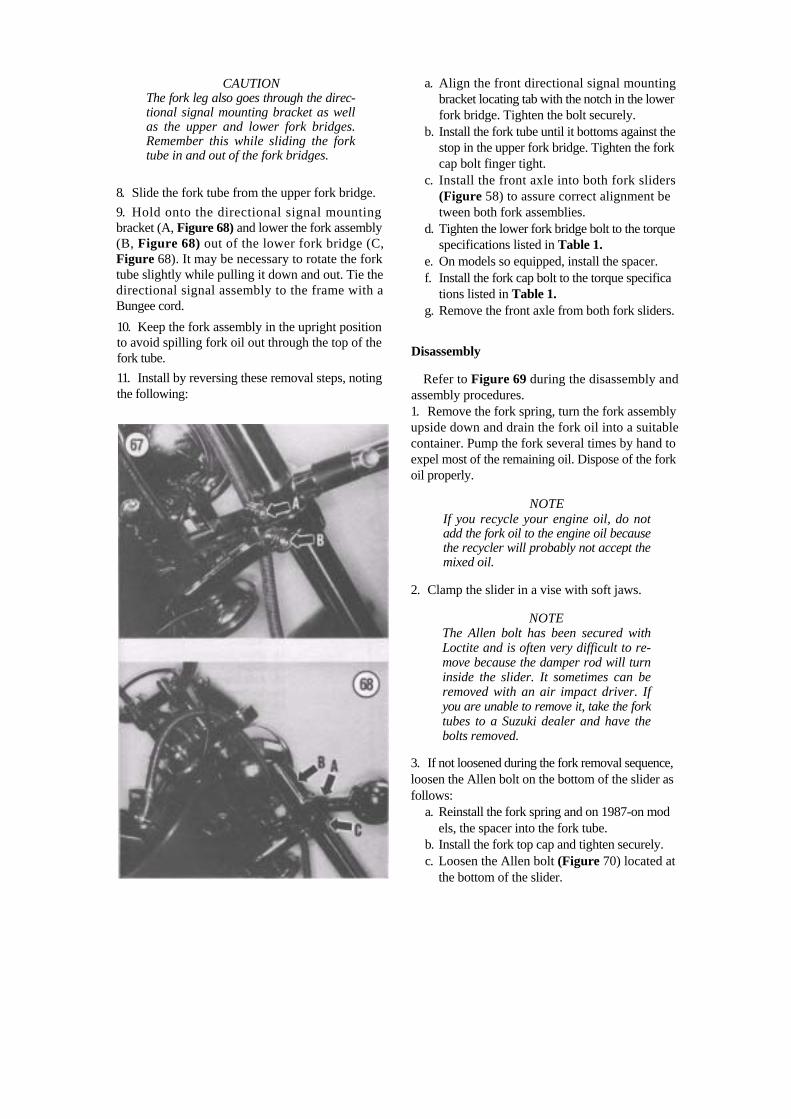
CAUTION The fork leg also goes through the direc-tional signal mounting bracket as well as the upper and lower fork bridges. Remember this while sliding the fork tube in and out of the fork bridges.
8. Slide the fork tube from the upper fork bridge. 9. Hold onto the directional signal mounting bracket (A, Figure 68) and lower the fork assembly (B, Figure 68) out of the lower fork bridge (C, Figure 68). It may be necessary to rotate the fork tube slightly while pulling it down and out. Tie the directional signal assembly to the frame with a Bungee cord.
10. Keep the fork assembly in the upright position to avoid spilling fork oil out through the top of the fork tube. 11. Install by reversing these removal steps, noting the following:
a. Align the front directional signal mounting bracket locating tab with the notch in the lower fork bridge. Tighten the bolt securely.
b. Install the fork tube until it bottoms against the stop in the upper fork bridge. Tighten the fork cap bolt finger tight.
c. Install the front axle into both fork sliders (Figure 58) to assure correct alignment be tween both fork assemblies.
d. Tighten the lower fork bridge bolt to the torque specifications listed in Table 1.
e. On models so equipped, install the spacer. f. Install the fork cap bolt to the torque specifica
tions listed in Table 1. g. Remove the front axle from both fork sliders.
Disassembly
Refer to Figure 69 during the disassembly and assembly procedures. 1. Remove the fork spring, turn the fork assembly upside down and drain the fork oil into a suitable container. Pump the fork several times by hand to expel most of the remaining oil. Dispose of the fork oil properly.
NOTE If you recycle your engine oil, do not add the fork oil to the engine oil because the recycler will probably not accept the mixed oil.
2. Clamp the slider in a vise with soft jaws.
NOTE The Allen bolt has been secured with Loctite and is often very difficult to re-move because the damper rod will turn inside the slider. It sometimes can be removed with an air impact driver. If you are unable to remove it, take the fork tubes to a Suzuki dealer and have the bolts removed.
3. If not loosened during the fork removal sequence, loosen the Allen bolt on the bottom of the slider as follows:
a. Reinstall the fork spring and on 1987-on mod els, the spacer into the fork tube.
b. Install the fork top cap and tighten securely. c. Loosen the Allen bolt (Figure 70) located at
the bottom of the slider.

FORK ASSEMBLY
1. Fork cap bolt 2. O-ring 3. Spacer (1987-on) 4. Spring seat 5. Spring 6. Piston ring 7. Damper rod 8. Rebound spring 9. Fork tube
10. Fork tube bushing 11. Oil lock piece 12. Dust seal 13. Stopper ring 14. Oil seal 15. Washer 16. Slider bushing 17. Slider 18. Axle clamp bolt 19. Sealing washer 20. Allen bolt

NOTE If you have the special Suzuki tools used for fork disassembly, loosen the Allen bolt in Step 11.
4. Remove the Allen bolt and gasket from the slider. 5. Hold the upper fork tube in a vise with soft jaws and loosen the fork cap bolt.
WARNING Be careful when removing the fork cap bolt as the spring is under pressure. Protect your eyes accordingly.
6. Remove the fork cap bolt (Figure 71) from the fork tube. 7A. On 1985 and 1986 models, remove the spring seat and the fork spring. 7B. On 1987-on models, remove the spacer (A, Figure 72), spring seat (B, Figure 72) and the fork spring (C, Figure 72). 8. Remove the dust seal trim cap (Figure 73) from the slider. 9. Remove the dust seal (Figure 74) from the slider. 10. Remove the stopper ring (Figure 75) from the slider.

11. If the Allen bolt was not loosened before, use special Suzuki tools and perform the following:
a. Install the attachment "D" (part No. 09940- 34561) onto the "T" handle (part No. 09940- 34520) as shown in Figure 76.
b. Insert this special tool setup into the fork tube (Figure 77) and index it into the hex receptacle in the top of the damper rod to hold the damper rod in place.
c. Using an Allen wrench, loosen then remove the Allen bolt and washer from the base of the slider.
NOTE On this type of fork, force is needed to remove the fork tube from the slider.
12. Install the fork tube in a vise with soft jaws. 13. There is an interference fit between the bushing in the fork slider and the bushing on the fork tube. In order to remove the fork tube from the slider, pull hard on the fork tube using quick in-and-out strokes (Figure 78). Doing so will withdraw the bushing, washer and the oil seal from the slider.
NOTE It may be necessary to slightly heat the area on the slider around the oil seal prior to removal. Use a rag soaked in hot water; do not apply aflame directly to the fork slider.
14. Withdraw the fork tube from the slider.
NOTE Do not remove the fork tube bushing unless it is going to be replaced. Inspect it as described in this chapter.
15. Remove the oil lock piece from the damper rod.

16. Remove the damper rod and rebound spring from the slider. 17. Inspect the components as described in this chapter.
Inspection
1. Thoroughly clean all parts in solvent and dry them. Check the fork tube for signs of wear or scratches. 2. Check the damper rod for straightness. Figure 79 shows one method. The damper rod should be re placed if the runout is 0.2 mm (0.008 in.) or greater. 3. Make sure the oil holes (Figure 80) in the damper rod are clear. Clean out if necessary. 4. Inspect the damper rod and piston ring (Figure 81) for wear or damage. Replace as necessary. 5. Check the fork tube (A, Figure 82) for straightness. If bent or severely scratched, it should be replaced. 6. Check the slider (B, Figure 82) for dents or exterior damage that may cause the upper fork tube to stick. Replace if necessary. 7. Inspect the brake caliper mounting bosses (Fig ure 83) on the slider for cracks or other damage. If damaged, replace the slider. 8. Inspect the slider (Figure 84) and fork tube bush ings (Figure 85). If either is scratched or scored they

must be replaced. If the Teflon coating is worn off so that the copper base material is showing on ap-proximately 3/4 of the total surface, the bushing must be replaced. Refer to Figure 86. Also check for distortion on the washer; replace as necessary. 9. Inspect the fork cap bolt threads in the fork tube (Figure 87) for wear or damage. Clean up with the appropriate size metric tap if necessary. 10. Inspect the fork cap bolt threads (Figure 88) for wear or damage. Clean up with the appropriate size metric die if necessary. 11. Inspect the oil seal seating area (Figure 89) in the slider for damage or burrs. Clean up if neces sary. 12. Inspect the gasket on the Allen bolt (Figure 90); replace if damaged. 13. Measure the un-compressed length of the fork spring (not rebound spring) as shown in Figure 91. If the spring has sagged to the service limit
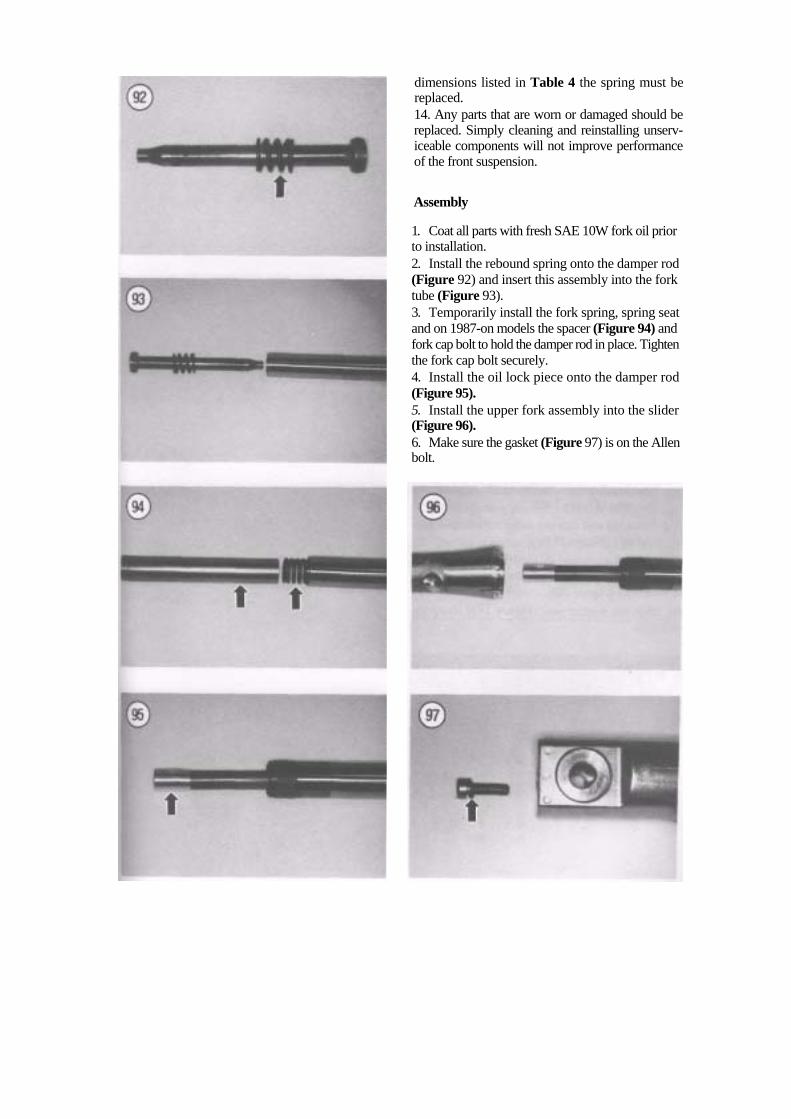
dimensions listed in Table 4 the spring must be replaced. 14. Any parts that are worn or damaged should be replaced. Simply cleaning and reinstalling unserv-iceable components will not improve performance of the front suspension.
Assembly
1. Coat all parts with fresh SAE 10W fork oil prior to installation. 2. Install the rebound spring onto the damper rod (Figure 92) and insert this assembly into the fork tube (Figure 93). 3. Temporarily install the fork spring, spring seat and on 1987-on models the spacer (Figure 94) and fork cap bolt to hold the damper rod in place. Tighten the fork cap bolt securely. 4. Install the oil lock piece onto the damper rod (Figure 95). 5. Install the upper fork assembly into the slider (Figure 96). 6. Make sure the gasket (Figure 97) is on the Allen bolt.

7. Apply blue Loctite (No. 242) to the threads of the Allen bolt prior to installation. Install it in the fork slider and tighten to the torque specification listed in Table 1. 8. Slide the fork slider bushing (A, Figure 98) and the washer (B, Figure 98) down the fork tube and rest it on top of the fork slider. 9. Install the new oil seal as follows:
a. Coat the new seal with fresh SAE 10W fork oil.
b. Position the seal with the open groove facing upward and slide the oil seal (C, Figure 98) down onto the fork tube.
NOTE The following Suzuki special tool (Fig-ure 99) is very expensive. If you work on a lot of different bikes this special tool is a must for your tool box. It is adjust-able and will work on almost all Japa-nese fork assemblies (including Japanese "Showa" forks equipped on some late model Harley Davidsons).
c. Slide the Suzuki special tool Front Fork Oil Seal Installer (part No. 09940-50112) down the fork tube (Figure 100).
d. Drive the seal into the slider with Suzuki spe cial tool (Figure 101).
e. Drive the oil seal in until the groove in the slider can be seen above the top surface of the oil seal (Figure 102).
10. Slide the stopper ring (Figure 103) down the fork tube.

11. Install the stopper ring and make sure it is completely seated in the groove in the fork slider (Figure 104). 12. Install the dust seal (Figure 74) into the slider. Press it in until it is completely seated. 13. Install the dust seal trim cap (Figure 73) onto the slider. Index it into the groove in the slider (Figure 105). 14. Unscrew the fork cap bolt, then remove the fork spring, spring seat and on 1987-on models the spacer from the fork tube.
NOTE Suzuki recommends that the fork oil level be measured, if possible, to ensure a more accurate filling.
NOTE To measure the correct amount of fluid, use a plastic baby bottle. These bottles have measurements in milliliters (ml) on the side.
15. Compress the fork completely. 16. Add the recommended amount of SAE 10W fork oil to the fork assembly listed in Table 3. 17. Hold the fork assembly as close to perfect ver tical as possible. 18. Use an accurate ruler or the Suzuki oil level gauge (part No. 09943-74111), or equivalent (Fig ure 106), to achieve the correct oil level listed in Table 3. Refer to Figure 107.

NOTE An oil level measuring devise can be made as shown in Figure 108. Position the lower edge of the hose clamp the specified oil level distance up from the small diameter hole. Fill the fork with a few mi's more than the required amount of oil. Position the hose clamp on the top edge of the fork tube and draw out the excess oil. Oil is sucked out until the level reaches the small diameter hole. A precise oil level can be achieved with this simple device.
19. Allow the oil to settle completely and recheck the oil level measurement. Adjust the oil level if necessary.
20. Install the fork spring with the closer wound coils (Figure 109) going in last. 21. Inspect the O-ring seal (Figure 110) on the fork cap bolt; replace if necessary. 22. Do not install the spring seat, spacer (1987-on models) or the top fork cap bolt at this time. Hold the fork assembly upright so the fork oil will not drain out. 23. Install the fork assemblies as described in this chapter. 24. After the fork assembly has been installed; install the spring seat, and on 1987-on models, the spacer. 25. Install the top fork cap bolt and tighten to the torque specification listed in Table 1. 26. Repeat this procedure for the other fork assembly.
OIL SUCTION GUN
Oil suction guns available at most auto parts stores

Table 1 FRONT SUSPENSION TIGHTENING TORQUES Item N.m ft.-lb. Front axle 36-52 26-37.5 Front axle nut 36-52 26-37.5 Front axle pinch bolt
1985-1991 15-25 11-181992-on 18-28 13-20
Brake disc bolts 15-25 11-18Handlebar upper holder Allen bolts 12-20 8.5-14.5 Master cylinder clamp bolts (brake and clutch) 5-8 3.5-6.0 Steering stem
Nut 40-50 29-36Cap nut 60-100 43.5-72.5
Fork cap bolt 25-30 18-21.5 Fork bridge lower clamp bolts 20-30 14.5-21.5 Fork slider Allen bolt 15-25 11-18
Table 2 TIRE INFLATION PRESSURE (COLD)*
Tire Pressure Front Rear Load psi kPa psl kPa Solo riding 28 200 32 225 Dual riding 32 225 36 250 * Tire inflation pressure for factory equipped tires. Aftermarket tires may require different inflation pressure.
Table 3 FORK OIL CAPACITY AND DIMENSIONS Front fork oil capacity (each fork leg) 1985-1989 Right-hand fork 358ml 12.1 oz. Left-hand fork 370ml 12.5oz. 1990-1991 U.S. 383ml 13.4oz. U.K. and Canada 394ml 13.8oz. 1992-1993 386ml 13.5OZ. 1994-on 412ml 14.5oz. Front fork oil level dimension 1985-1989 153 mm 6.02 in 1990-1991 U.S. and U.K. 175mm 6.89 in. Canada 187 mm 7.36 in. 1992-1993 U.S., Canada and U.K. 178 mm 7.01 in. 1994-on 177mm 6.97 in. Fork oil type SAE 1 0W fork oil

Table 4 FRONT SUSPENSION SPECIFICATIONS Item Wear limit Front axle runout 0.2 mm (0.01 in.) Front wheel rim runout Radial 2.0 mm (0.08 in.) Axial 2.0 mm (0.08 in.) Front fork spring free length limit 1 985-1 986 563 mm (22.2 in.) 1987 360.8 mm (14.20 in.) 1 988-on 348.3 mm (1 3.71 in.) Fork oil Capacity per leg 1985-1986 3.37 ml (11.4 U.S. oz. [11.9 Imp. oz.]) 1 987 3.55 ml (1 2.0 U.S. oz. [1 2.5 Imp. oz.]) 1 988-on 4.1 3 ml (1 4.0 U.S. oz. [1 4.5 Imp. oz.]) Oil level each leg 1 985-1 986 1 44 mm (5.67 in.) 1987 117.4 mm (4.62 in.). 1 988-on 1 24.3 mm (4.89 in.)