
10RCS ANALYSIS OF MORTAR AND ARTILLERY SHELLS · RCS ANALYSIS OF MORTAR AND ARTILLERY SHELLS...
8
ATMS INDIA 2015 The 8 th Annual International Conference ATMS -2015, Bangalore © ATMS (INDIA) RCS ANALYSIS OF MORTAR AND ARTILLERY SHELLS Arokiasamy, Virendrakumar, Beenamole K.S Electronics and Radar Development Establishment Defence Research and Development Organization Bangalore-560093, India. Ph: 080-25025935; Fax: 080-25241074. Email: beena[email protected] Abstract: This paper presents the analysis of radar cross section (RCS) of artillery shells and mortars of different calibers with the different aspect angles of the projectile based on MOM method. The modelling of different artillery shells of different dimensions have been carried out and simulates their Radar Cross Section variation at different frequencies and different firing angles. Typical studies have been presented in this paper for a typical caliber artillery shell and mortar. The analysis has been carried out using MOM based commercial tool CONCERTO. A comparison of the RCS with respect to different aspect angles over the frequency Bandwidth is provided. A comparison of the probability of detection of different artillery shells depends on the RCS (due to variation of RCS with aspect angle) also have been provided. This study has helped a lot in modifying the detection algorithm and met specifications of the radar for detection of all the artillery shell and mortar. Keywords: radar cross section, aspect angle, probability of detection I. INTRODUCTION Weapon Locating Radar (WLR) has been designed and developed to locate hostile indirect fire weapons such as artillery, mortars and rockets. Since World War I, indirect fire weapons have been the main source of casualties in the battlefield. By tracking the launched projectile flight, WLR radar can accurately locate the weapon before the projectile impacts the ground and thereby allow counter fire to be made on the weapon in time. If the position and velocity of a projectile in flight were known, the location of the firing weapon could be determined by extrapolating the trajectory back to the ground. The WLR radars have greatly reduced the effectiveness of indirect fire weapons and as a consequence saved many lives many times. Fig.1 shows a typical set up of Weapon Locating Radar. To have an accurate detection of targets it is required to know the radar cross section of targets a priori to avoid missing detections. The present report aims at analyzing the radar cross sections of the various weapons and its variation w.r.t. frequency of radar and the different aspect angles. The analysis has been carried out using MOM based commercial tool form Vector fields, i.e. CONCERTO software. This paper presented the RCS analysis of different artillery shells of different dimensions and mortar at different frequencies and different firing angles. Accurate prediction of target RCS is critical in order to design and develop robust discrimination algorithms. This study has
-
Upload
vuongkhanh -
Category
Documents
-
view
255 -
download
1
Transcript of 10RCS ANALYSIS OF MORTAR AND ARTILLERY SHELLS · RCS ANALYSIS OF MORTAR AND ARTILLERY SHELLS...
ATMS INDIA
2015
The 8th
Annual International Conference ATMS -2015, Bangalore
© ATMS (INDIA)
RCS ANALYSIS OF MORTAR AND ARTILLERY SHELLS
Arokiasamy, Virendrakumar, Beenamole K.S
Electronics and Radar Development Establishment Defence Research and Development Organization
Bangalore-560093, India. Ph: 080-25025935; Fax: 080-25241074.
Email: [email protected]
Abstract:
This paper presents the analysis of radar cross section (RCS) of artillery shells and mortars of different calibers with the different aspect angles of the projectile based on MOM method. The modelling of different artillery shells of different dimensions have been carried out and simulates their Radar Cross Section variation at different frequencies and different firing angles. Typical studies have been presented in this paper for a typical caliber artillery shell and mortar. The analysis has been carried out using MOM based commercial tool CONCERTO. A comparison of the RCS with respect to different aspect angles over the frequency Bandwidth is provided. A comparison of the probability of detection of different artillery shells depends on the RCS (due to variation of RCS with aspect angle) also have been provided. This study has helped a lot in modifying the detection algorithm and met specifications of the radar for detection of all the artillery shell and mortar.
Keywords: radar cross section, aspect angle, probability of detection
I. INTRODUCTION
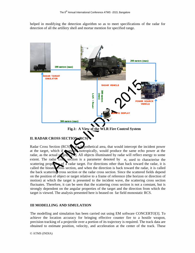
Weapon Locating Radar (WLR) has been designed and developed to locate hostile indirect fire weapons such as artillery, mortars and rockets. Since World War I, indirect fire weapons have been the main source of casualties in the battlefield. By tracking the launched projectile flight, WLR radar can accurately locate the weapon before the projectile impacts the ground and thereby allow counter fire to be made on the weapon in time. If the position and velocity of a projectile in flight were known, the location of the firing weapon could be determined by extrapolating the trajectory back to the ground. The WLR radars have greatly reduced the effectiveness of indirect fire weapons and as a consequence saved many lives many times. Fig.1 shows a typical set up of Weapon Locating Radar. To have an accurate detection of targets it is required to know the radar cross section of targets a priori to avoid missing detections. The present report aims at analyzing the radar cross sections of the various weapons and its variation w.r.t. frequency of radar and the different aspect angles. The analysis has been carried out using MOM based commercial tool form Vector fields, i.e. CONCERTO software.
This paper presented the RCS analysis of different artillery shells of different dimensions and mortar at different frequencies and different firing angles. Accurate prediction of target RCS is critical in order to design and develop robust discrimination algorithms. This study has
ATMS INDIA
2015
The 8th
Annual International Conference ATMS -2015, Bangalore
© ATMS (INDIA)
helped in modifying the detection algorithm so as to meet specifications of the radar for detection of all the artillery shell and mortar mention for specified range.
II. RADAR CROSS SECTION (RCS)
Radar Cross Section (RCS) is the hypothetical area, that would intercept the incident power at the target, which if scattered isotropically, would produce the same echo power at the radar, as the actual target[1,2,4]. All objects illuminated by radar will reflect energy to some extent. The radar cross section is a parameter denoted by , used to characterise the scattering properties of a radar target. For directions other than back toward the radar, it is called the bistatic cross section, and when the direction is back toward the radar, it is called the back scattering cross section or the radar cross section. Since the scattered fields depend on the position of object or target relative to a frame of reference (the horizon or direction of motion) at which the target is presented to the incident wave, the scattering cross section fluctuates. Therefore, it can be seen that the scattering cross section is not a constant, but is strongly dependent on the angular properties of the target and the direction from which the target is viewed. The analysis presented here is beased on far field monostatic RCS.
III MODELLING AND SIMULATION
The modelling and simulation has been carried out using EM software CONCERTO[3]. To achieve the location accuracy for bringing effective counter fire to a hostile weapon, precision tracking of a projectile over a portion of its trajectory is required. The track data are obtained to estimate position, velocity, and acceleration at the center of the track. These
RADAR TARGET SIMULATOR
POWER SOURCEVEHICLE
200 meters (max)
100 meters (max)
LA
N +
Pow
er
300 meters
(max)
REMOTE DISPLAY
300 meters (max)
RADAR VEHICLE
RADAR TARGET SIMULATOR
POWER SOURCEVEHICLE
200 meters (max)
100 meters (max)
LA
N +
Pow
er
300 meters
(max)
REMOTE DISPLAY
300 meters (max)
RADAR VEHICLE
Fig.1: A View of the WLR Fire Control System

ATMS INDIA
2015
The 8th
Annual International Conference ATMS -2015, Bangalore
© ATMS (INDIA)
estimates are then extrapolated back to the ground plane. If the position and velocity of a projectile in flight are known, then location of the firing weapon could be determined by extrapolating the trajectory back to the ground. For an artillery weapon firing at an elevation angle of 150 to 200, and located 30 Km from the radar, the maximum elevation angle is less than 60. Hence the radar will need to complete detection and track while the projectile is still close to the horizon and as a consequence the radar will be exposed to reflections from terrain, birds and insects. Hence in the analysis presented in the report RCS variation at different firing angle has been studied and simulations study is being presented. The shells and mortar models have been shown in Fig.2. The analysis have been carried out on these objects by varying the firing angle, frequency and polarization. Simulated outputs for typical cases have been presented. Fig. 2. The launch of the objects have been shown in Fig.3.
Fig. 3 Launch of the objects with different firing angles
Launch Impact Points
Firing angle
Fig. 2 Model of the shells and mortar
caliber 1
caliber 2
caliber 3
mortar

ATMS INDIA
2015
The 8th
Annual International Conference ATMS -2015, Bangalore
© ATMS (INDIA)
IV. RESULTS
Typical Simulated RCS have been presented for the different objects as a function of the aspect angle. The caliber1 shell has been illuminated with 3D plane wave the scattered field diagram has been shown in Fig.4. Fig.4 shows RCS when artillery shell has been illuminated with vertically polarized plane wave and the echo received by vertically polarized antenna(SigVV). Fig.5 also shows RCS when the shell is illuminated by horizontally polarized plane wave and the echo received by horizontally polarized antenna(SigHH). Fig.6 shows the 3D plane wave the scattered field diagram of mortar when illuminated with plane wave. Fig.7 shows RCS when artillery shell has been illuminated with vertically and horizontally polarized plane wave and the echo received.
Model of shell
Field distribution
Vertical
Horizontal
Aspect Angle
RC
S(dB
sm)
Fig. 5: 3D view of the Scattered field distribution of 155mm shell
Fig. 4: 3D view of the Scattered field distribution of caliber 1shell
-20
-0
-10
-30
-40
Fi
eld
Dis
trib
utio
n (d
Bsm
)

ATMS INDIA
2015
The 8th
Annual International Conference ATMS -2015, Bangalore
© ATMS (INDIA)
Fig. 6: 3D Illumination of RCS of MORTAR around the model
Vertical
Horizontal
Fig. 7: RCS of 81mm MORTAR Vertical -Vertical and Horizontal Horizontal POL.
Cut, = -900 Varying from 00 to 1800
-10
-20
-30
-40
Fi
eld
Dis
trib
utio
n(dB
sm)
RC
S(dB
sm)
Aspect Angle
ATMS INDIA
2015
The 8th
Annual International Conference ATMS -2015, Bangalore
© ATMS (INDIA)
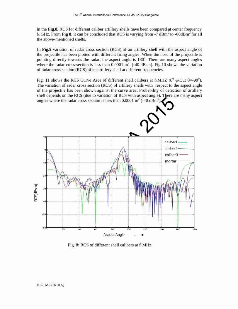
In the Fig.8, RCS for different caliber artillery shells have been compared at center frequency f0 GHz. From Fig 8. it can be concluded that RCS is varying from -7 dBm2 to -60dBm2 for all the above-mentioned shells.
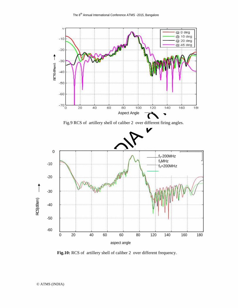
In Fig.9 variation of radar cross section (RCS) of an artillery shell with the aspect angle of the projectile has been plotted with different firing angles. When the nose of the projectile is pointing directly towards the radar, the aspect angle is 1800. There are many aspect angles where the radar cross section is less than 0.0001 m2. (-40 dBsm). Fig.10 shows the variation of radar cross section (RCS) of an artillery shell at different frequencies.
Fig. 11 shows the RCS Curve Area of different shell calibers at f0MHZ (00 -Cut =-900). The variation of radar cross section (RCS) of artillery shells with respect to the aspect angle of the projectile has been shown against the curve area. Probability of detection of artillery shell depends on the RCS (due to variation of RCS with aspect angle). There are many aspect angles where the radar cross section is less than 0.0001 m2 (-40 dBm2).
Fig. 8: RCS of different shell calibers at f0MHz
RC
S(dB
sm)
Aspect Angle
caliber1
caliber2
caliber3
mortar
ATMS INDIA
2015
The 8th
Annual International Conference ATMS -2015, Bangalore
© ATMS (INDIA)
Fig.9 RCS of artillery shell of caliber 2 over different firing angles.
RC
S(dB
sm)
Aspect Angle
Fig.10: RCS of artillery shell of caliber 2 over different frequency.
0
40
60
120
160
180
20
60
80
140
-60
-50
-40
-30
-20
-10
0
f0-200MHz
f0MHz
f0+200MHz
RC
S(dB
sm)
aspect angle

ATMS INDIA
2015
The 8th
Annual International Conference ATMS -2015, Bangalore
© ATMS (INDIA)
V. CONCLUSION
The RCS of the Shells, have been simulated for different frequencies , different polarisations and for different firing angles. Typical RCS values have been presented in the paper as a function of aspect angle. The results show that the RCS fluctuates as a function of firing angle, polarization and frequency. There are many possibilities for a typical shell to have RCS of less than -40dBsm. The probability of detection with typical RCS curve also been presented. The results has helped in modifying the tracking algorithm of the radar for a better detection.
Acknowledgment: The authors are thankful towards the Director, LRDE for his kind permission to publish this paper.
References [1]. V.G. Borkar et.al, Radar Cross-section Measurement Techniques. Defence Science journal, March-2010. [2]. Marcelo Alexandre Souza Miacci1, Indoor Radar Cross Section Measurements of Simple Targets ,.J.of Aerosp. Technol.Manag. Vol.4 , pp 25-32, Jan-March 2012. [3]. EM Simulation Software, Concerto, Vector Fields, UK.
[4].K.M.Siegel.et.al, "Studies in Radar Cross Sections-XII", Report, University of Michigun, 1958.
Fig. 11: RCS Curve Area of mortar and shells at f0 GHz (0 deg elevation)
RC
S(dB
sm)
Area(%)
caliber1
caliber2
caliber3
mortar


![Corrigendum to Simulation-Based Early Prediction of Rocket, Artillery… · 2019. 7. 30. · Rocket, Artillery, and Mortar Trajectories and Real-Time OptimizationforCounter-RAMSystems”[],therewasan](https://static.fdocuments.net/doc/165x107/61157016ca19f0297e523b0f/corrigendum-to-simulation-based-early-prediction-of-rocket-artillery-2019-7-30.jpg)