10GB Process and Control Valves€¦ · · 2017-01-10Solenoid valves I Process and control...
76
System Catalog 2 Solenoid valves I Process and control valves I Pneumatics Sensors I MicroFluidics I MFC and proportional valves The smart choice of Fluid Control Systems
Transcript of 10GB Process and Control Valves€¦ · · 2017-01-10Solenoid valves I Process and control...

System Catalog 2
Solenoid valves I Process and control valves I Pneumatics
Sensors I MicroFluidics I MFC and proportional valves
The smart choice of Fluid Control Systems

All technical details were valid at the
time of going to print. Since we are
continuously developing our products,
we reserve the right to make technical
alterations. Unfortunately, we also
cannot fully exclude possible errors.
Please understand that no legal claims
can be made bared upon either the
details given or the illustrations and
descriptions provided.
Texts, photographs, technical draw-
ings and any other form of presenta-
tions made in this publication are pro-
tected by copyright and property of
Bürkert Fluid Control Systems GmbH
& Co. KG.
Any further use in print or electronic
media requires the express approval
of Bürkert GmbH & Co. KG. Any form
of duplication, translation, processing,
recording on microfilm or saving in
electronic systems is prohibited with-
out the express approval of
Bürkert GmbH & Co. KG.
Bürkert GmbH & Co. KG
Fluid Control Systems
Christian-Bürkert-Straße 13-17
D-74653 Ingelfingen
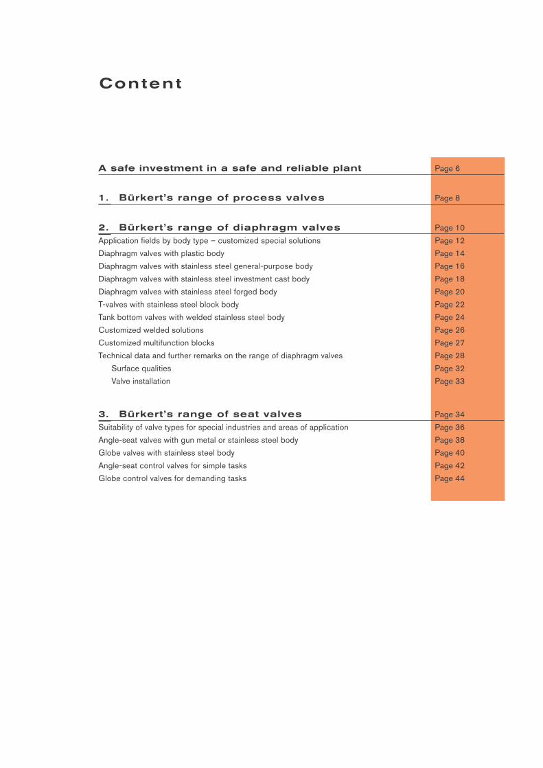
A safe investment in a safe and reliable plant Page 6
1. Bürkert’s range of process valves Page 8
2. Bürkert’s range of diaphragm valves Page 10
Application fields by body type – customized special solutions Page 12
Diaphragm valves with plastic body Page 14
Diaphragm valves with stainless steel general-purpose body Page 16
Diaphragm valves with stainless steel investment cast body Page 18
Diaphragm valves with stainless steel forged body Page 20
T-valves with stainless steel block body Page 22
Tank bottom valves with welded stainless steel body Page 24
Customized welded solutions Page 26
Customized multifunction blocks Page 27
Technical data and further remarks on the range of diaphragm valves Page 28
Surface qualities Page 32
Valve installation Page 33
Content
3. Bürkert’s range of seat valves Page 34
Suitability of valve types for special industries and areas of application Page 36
Angle-seat valves with gun metal or stainless steel body Page 38
Globe valves with stainless steel body Page 40
Angle-seat control valves for simple tasks Page 42
Globe control valves for demanding tasks Page 44
4. Bürkert’s range of positioners and control heads Page 46
Typical application fields of Bürkert positioners and control heads Page 48
Positioner, Type 8630 TopControl Continuous Page 50
Positioner, Type 8635 SideControl S/HART/PROFIBUS PA Page 52
Positioner, Type 1067 SideControl Page 54
Control head, Type 8631 TopControl ON/OFF Page 56
Control head, Type 1066 Page 58
Technology and functions of digital electropneumatic positioners Page 60
Functional structure Page 60
Process control loop Page 60
Integrated process controller Page 61
Operating structure of the positioners Page 62
Typical functions and options Page 63
Technology and functions of electropneumatic control heads Page 65
5. Accessories and other products Page 68
Valves for pneumatically operated actuators Page 68
Accessories for pneumatically operated actuators Page 69
Other process valves Page 70
I/O box and remote I/O systems Page 70
Sensors, transmitters and measuring instruments for process engineering Page 71
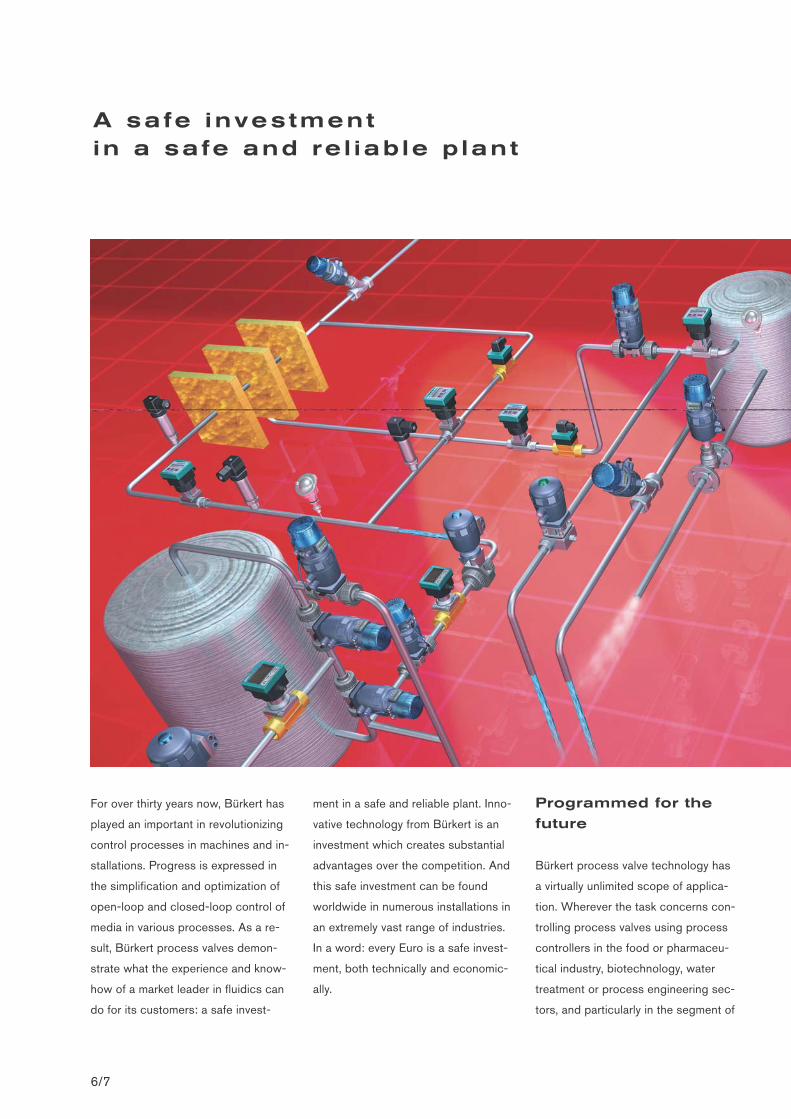
For over thirty years now, Bürkert has
played an important in revolutionizing
control processes in machines and in-
stallations. Progress is expressed in
the simplification and optimization of
open-loop and closed-loop control of
media in various processes. As a re-
sult, Bürkert process valves demon-
strate what the experience and know-
how of a market leader in fluidics can
do for its customers: a safe invest-
ment in a safe and reliable plant. Inno-
vative technology from Bürkert is an
investment which creates substantial
advantages over the competition. And
this safe investment can be found
worldwide in numerous installations in
an extremely vast range of industries.
In a word: every Euro is a safe invest-
ment, both technically and economic-
ally.
Programmed for the
future
Bürkert process valve technology has
a virtually unlimited scope of applica-
tion. Wherever the task concerns con-
trolling process valves using process
controllers in the food or pharmaceu-
tical industry, biotechnology, water
treatment or process engineering sec-
tors, and particularly in the segment of
A safe investment in a safe and re l iab le p lant
6/7
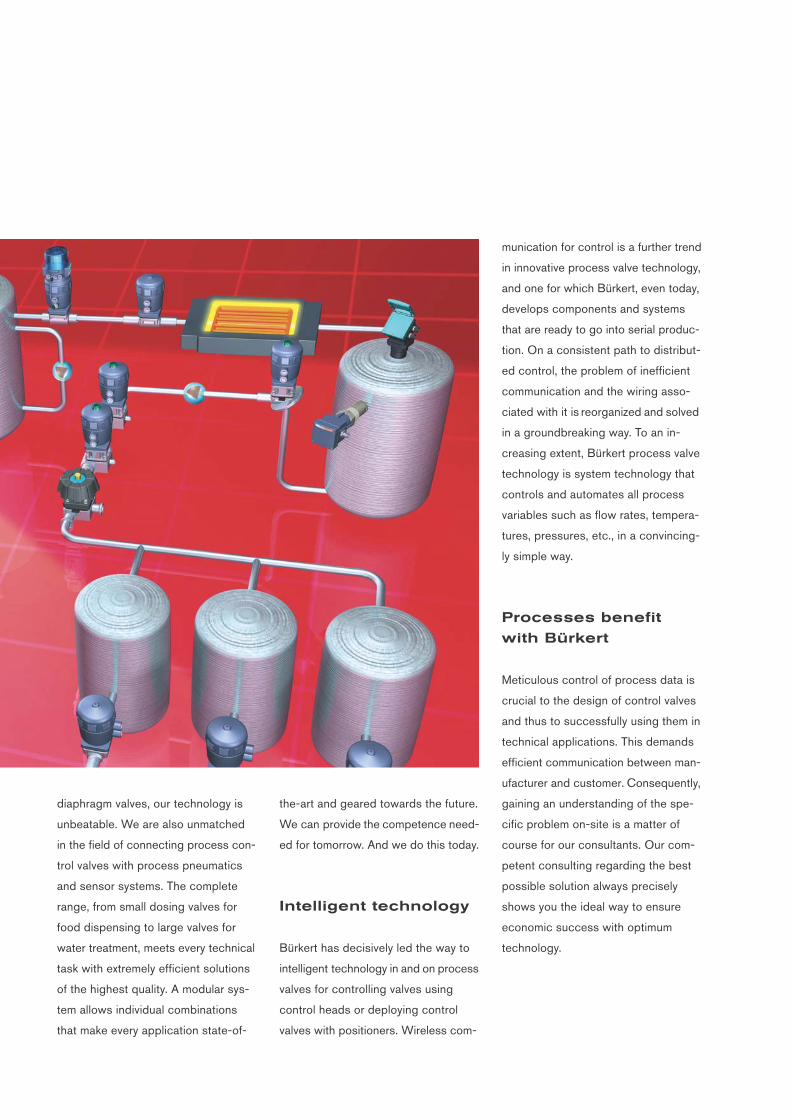
diaphragm valves, our technology is
unbeatable. We are also unmatched
in the field of connecting process con-
trol valves with process pneumatics
and sensor systems. The complete
range, from small dosing valves for
food dispensing to large valves for
water treatment, meets every technical
task with extremely efficient solutions
of the highest quality. A modular sys-
tem allows individual combinations
that make every application state-of-
the-art and geared towards the future.
We can provide the competence need-
ed for tomorrow. And we do this today.
Intelligent technology
Bürkert has decisively led the way to
intelligent technology in and on process
valves for controlling valves using
control heads or deploying control
valves with positioners. Wireless com-
munication for control is a further trend
in innovative process valve technology,
and one for which Bürkert, even today,
develops components and systems
that are ready to go into serial produc-
tion. On a consistent path to distribut-
ed control, the problem of inefficient
communication and the wiring asso-
ciated with it is reorganized and solved
in a groundbreaking way. To an in-
creasing extent, Bürkert process valve
technology is system technology that
controls and automates all process
variables such as flow rates, tempera-
tures, pressures, etc., in a convincing-
ly simple way.
Processes benefit
with Bürkert
Meticulous control of process data is
crucial to the design of control valves
and thus to successfully using them in
technical applications. This demands
efficient communication between man-
ufacturer and customer. Consequently,
gaining an understanding of the spe-
cific problem on-site is a matter of
course for our consultants. Our com-
petent consulting regarding the best
possible solution always precisely
shows you the ideal way to ensure
economic success with optimum
technology.
PRO
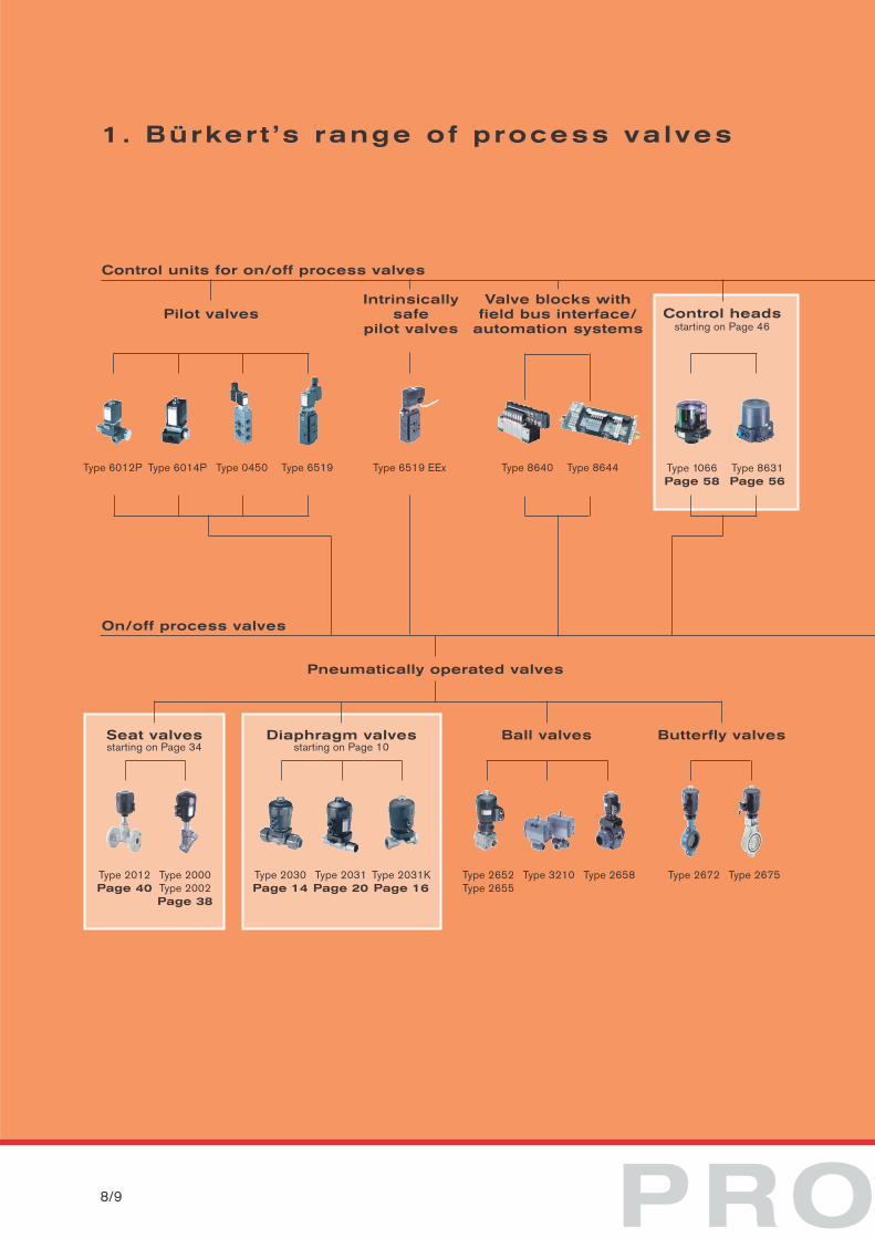
1. Bürker t ’s range of process va lves
8/9
Diaphragm valvesstarting on Page 10
Ball valves Butterfly valves
Control units for on/off process valves
On/off process valves
Pneumatically operated valves
Pilot valvesIntrinsically
safe pilot valves
Type 6012P Type 6014P Type 0450 Type 6519 EExType 6519
Type 2030Page 14
Type 2031Page 20
Type 2031KPage 16
Type 2652Type 2655
Type 3210 Type 2658
Control headsstarting on Page 46
Type 1066Page 58
Type 8631Page 56
Type 2672 Type 2675
Valve blocks withfield bus interface/
automation systems
Type 8640 Type 8644
Seat valvesstarting on Page 34
Type 2012Page 40
Type 2000Type 2002Page 38
CESS VALVES
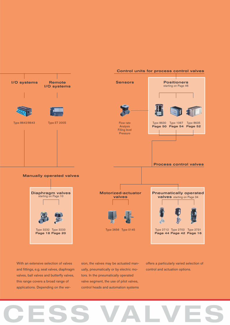
I/O systems
Type 8642/8643 Type ET 200S
RemoteI/O systems
Manually operated valves
Pneumatically operatedvalves starting on Page 34
Diaphragm valvesstarting on Page 10
Control units for process control valves
Process control valves
Type 2712Page 44
Type 2702Page 42
Type 2731Page 16
Motorized-actuatorvalves
Type 2656 Type 0145Type 3232Page 18
Type 3233Page 20
Positionersstarting on Page 46
Sensors
Type 8630Page 50
Flow rateAnalysis
Filling levelPressure
Type 1067Page 54
Type 8635Page 52
With an extensive selection of valves
and fittings, e.g. seat valves, diaphragm
valves, ball valves and butterfly valves,
this range covers a broad range of
applications. Depending on the ver-
sion, the valves may be actuated man-
ually, pneumatically or by electric mo-
tors. In the pneumatically operated
valve segment, the use of pilot valves,
control heads and automation systems
offers a particularly varied selection of
control and actuation options.
D I A P H R10/11
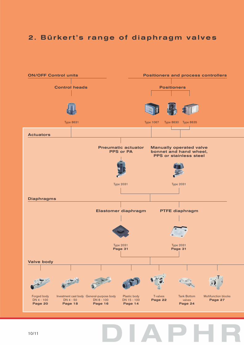
2. Bürker t ’s range of d iaphragm valves
ON/OFF Control units
Actuators
Pneumatic actuator PPS or PA
Type 2031
Control heads
Type 8631 Type 8630Type 1067 Type 8635
Manually operated valvebonnet and hand wheel,
PPS or stainless steel
Type 2031
Diaphragms
Valve body
Elastomer diaphragm
Type 2031Page 31
PTFE diaphragm
Type 2031Page 31
Forged bodyDN 4 - 100Page 20
Investment cast bodyDN 4 - 50Page 18
General-purpose bodyDN 8 - 100Page 16
Plastic bodyDN 15 - 100Page 14
T-valvesPage 22
Tank Bottomvalves
Page 24
Multifunction blocksPage 27
Positioners and process controllers
Positioners
A G M VA LV E S
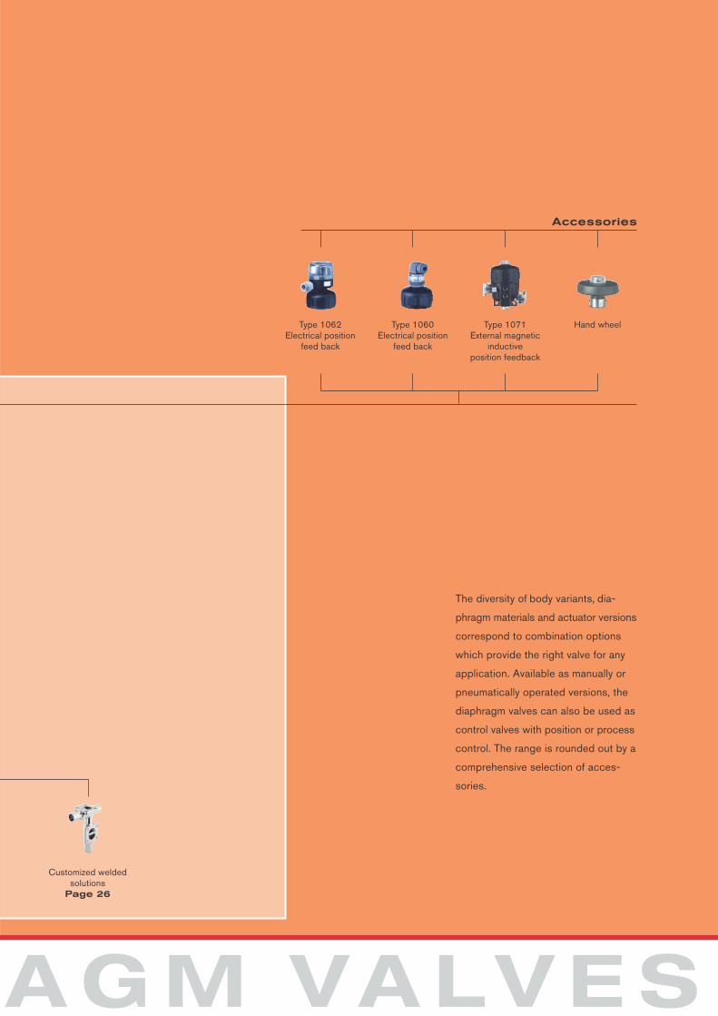
Accessories
Customized weldedsolutions
Page 26
Type 1062Electrical position
feed back
Type 1060Electrical position
feed back
Type 1071External magnetic
inductive position feedback
Hand wheel
The diversity of body variants, dia-
phragm materials and actuator versions
correspond to combination options
which provide the right valve for any
application. Available as manually or
pneumatically operated versions, the
diaphragm valves can also be used as
control valves with position or process
control. The range is rounded out by a
comprehensive selection of acces-
sories.
12/13
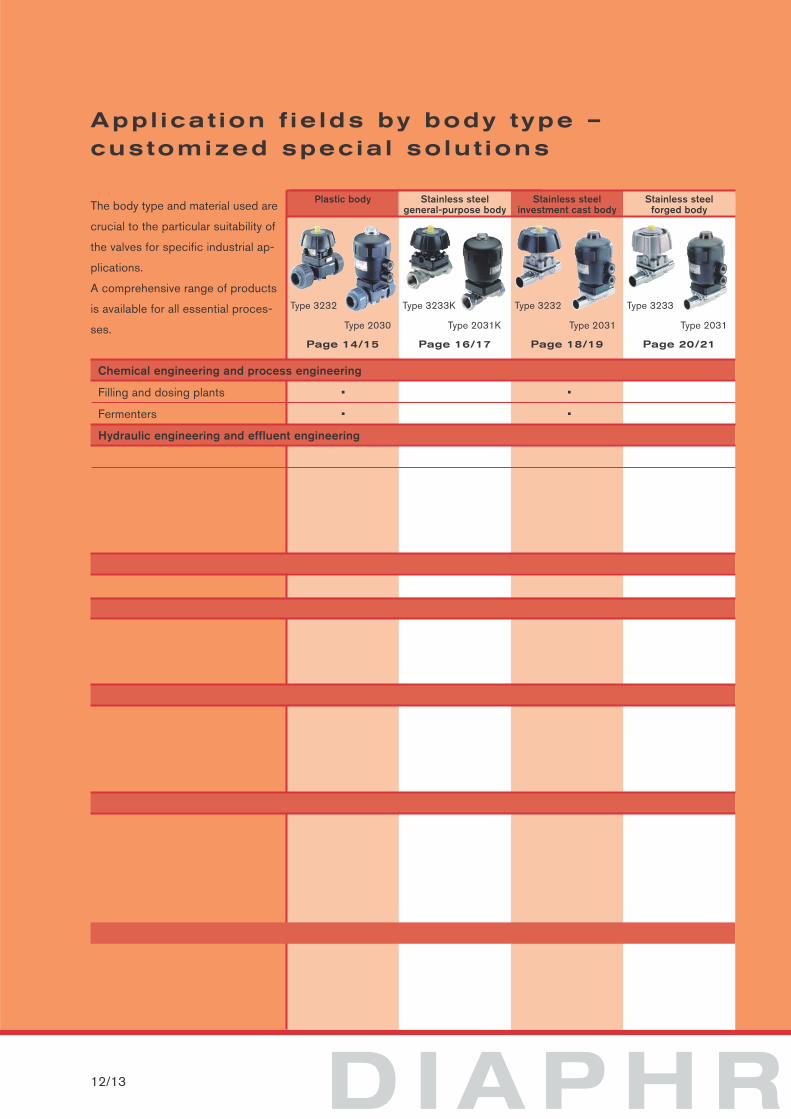
Appl icat ion f ie lds by body type – customized specia l so lut ions
Plastic body Stainless steelgeneral-purpose body
Stainless steelforged body
Stainless steelinvestment cast body
Type 3232
Type 2030
Type 3233K
Type 2031K
Type 3232
Type 2031
Page 14/15 Page 16/17
Type 3233
Type 2031
Page 20/21Page 18/19
D I A P H R
The body type and material used are
crucial to the particular suitability of
the valves for specific industrial ap-
plications.
A comprehensive range of products
is available for all essential proces-
ses.
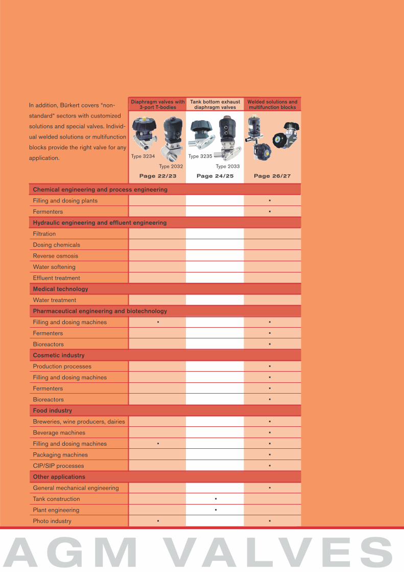
Chemical engineering and process engineering
Filling and dosing plants • •
Fermenters • •
Hydraulic engineering and effluent engineering
Diaphragm valves with3-port T-bodies
Tank bottom exhaust diaphragm valves
Welded solutions andmultifunction blocks
Type 3234
Type 2032
Type 3235
Type 2033
Page 22/23 Page 24/25 Page 26/27
A G M VA LV E S
In addition, Bürkert covers “non-
standard“ sectors with customized
solutions and special valves. Individ-
ual welded solutions or multifunction
blocks provide the right valve for any
application.
Chemical engineering and process engineering
Filling and dosing plants •
Fermenters •
Hydraulic engineering and effluent engineering
Filtration
Dosing chemicals
Reverse osmosis
Water softening
Effluent treatment
Medical technology
Water treatment
Pharmaceutical engineering and biotechnology
Filling and dosing machines • •
Fermenters •
Bioreactors •
Cosmetic industry
Production processes •
Filling and dosing machines •
Fermenters •
Bioreactors •
Food industry
Breweries, wine producers, dairies •
Beverage machines •
Filling and dosing machines • •
Packaging machines •
CIP/SIP processes •
Other applications
General mechanical engineering •
Tank construction •
Plant engineering •
Photo industry • •
D I A P H R
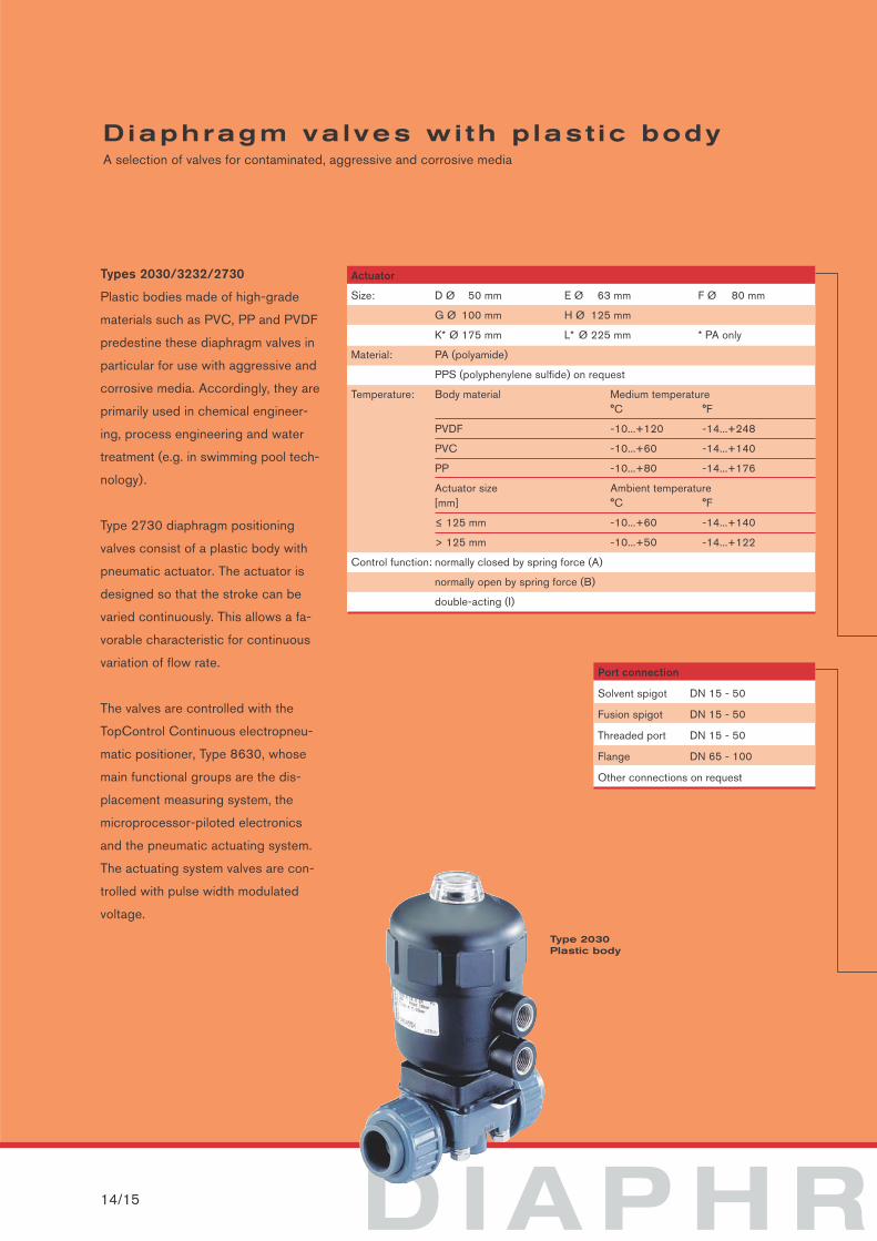
Diaphragm valves wi th p last ic bodyA selection of valves for contaminated, aggressive and corrosive media
14/15
Types 2030/3232/2730
Plastic bodies made of high-grade
materials such as PVC, PP and PVDF
predestine these diaphragm valves in
particular for use with aggressive and
corrosive media. Accordingly, they are
primarily used in chemical engineer-
ing, process engineering and water
treatment (e.g. in swimming pool tech-
nology).
Type 2730 diaphragm positioning
valves consist of a plastic body with
pneumatic actuator. The actuator is
designed so that the stroke can be
varied continuously. This allows a fa-
vorable characteristic for continuous
variation of flow rate.
The valves are controlled with the
TopControl Continuous electropneu-
matic positioner, Type 8630, whose
main functional groups are the dis-
placement measuring system, the
microprocessor-piloted electronics
and the pneumatic actuating system.
The actuating system valves are con-
trolled with pulse width modulated
voltage.
Port connection
Solvent spigot DN 15 - 50
Fusion spigot DN 15 - 50
Threaded port DN 15 - 50
Flange DN 65 - 100
Other connections on request
Actuator
Size: D Ø 50 mm E Ø 63 mm F Ø 80 mm
G Ø 100 mm H Ø 125 mm
K* Ø 175 mm L* Ø 225 mm * PA only
Material: PA (polyamide)
PPS (polyphenylene sulfide) on request
Temperature: Body material Medium temperature °C °F
PVDF -10...+120 -14...+248
PVC -10...+60 -14...+140
PP -10...+80 -14...+176
Actuator size Ambient temperature[mm] °C °F
≤ 125 mm -10...+60 -14...+140
> 125 mm -10...+50 -14...+122
Control function: normally closed by spring force (A)
normally open by spring force (B)
double-acting (I)
Type 2030Plastic body
A G M VA LV E S
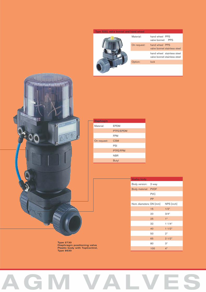
Material: hand wheel PPSvalve bonnet PPS
On request: hand wheel PPSvalve bonnet stainless steel
hand wheel stainless steelvalve bonnet stainless steel
Option: lock
Type 3232, valve bonnet and hand wheel
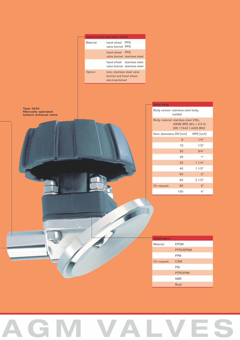
Diaphragm
Material: EPDM
PTFE/EPDM
FPM
On request: CSM
PSI
PTFE/FPM
NBR
Butyl
Vealve body
Body version: 2-way
Body material: PVDF
PVC
PP
Nom. diameters: DN [mm] NPS [inch]
15 1/2“
20 3/4“
25 1“
32 1 1/4“
40 1 1/2“
50 2“
65 2 1/2“
80 3“
100 4“
Type 2730 Diaphragm positioning valvePlastic body with TopControl, Type 8630
D I A P H R16/17
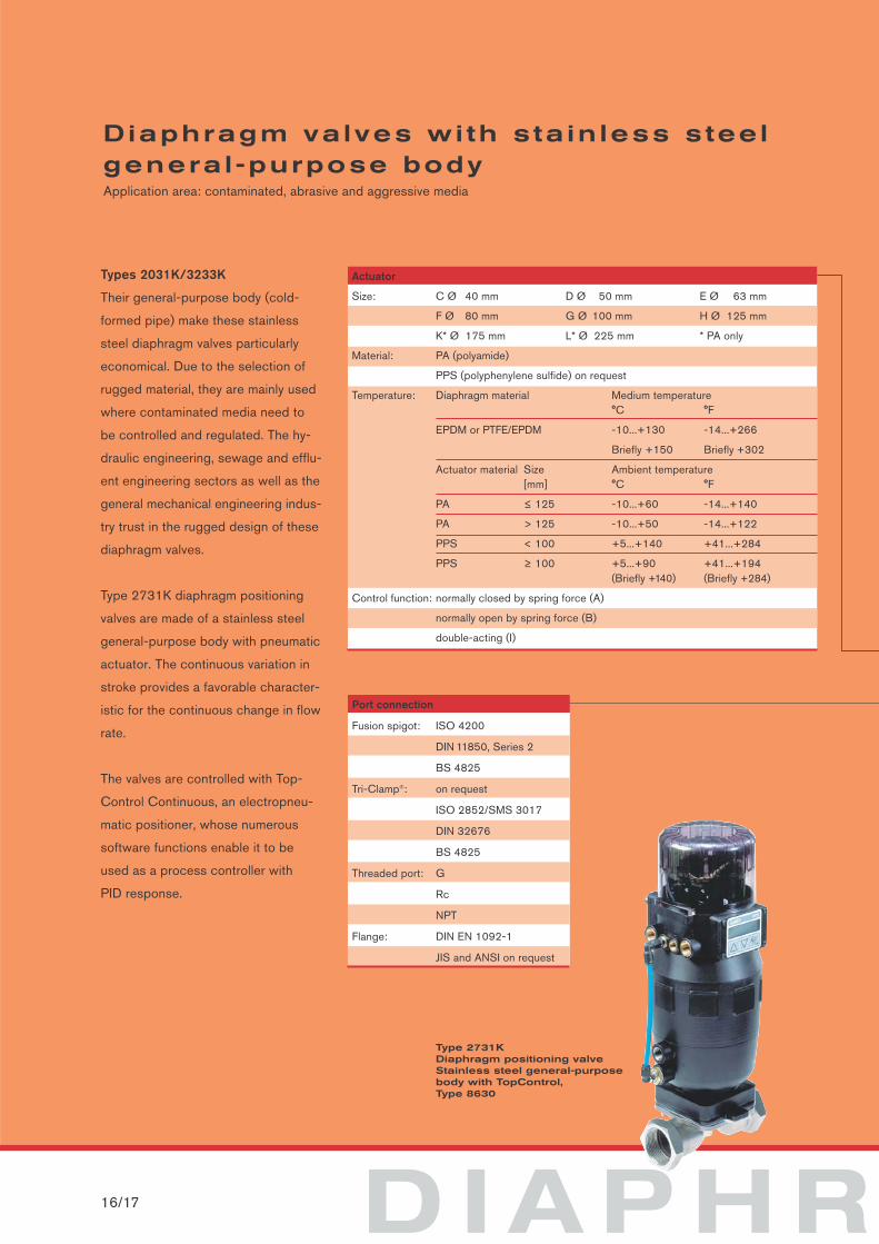
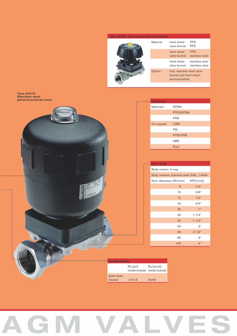
Diaphragm valves wi th s ta in less s tee lgenera l -purpose bodyApplication area: contaminated, abrasive and aggressive media
Types 2031K/3233K
Their general-purpose body (cold-
formed pipe) make these stainless
steel diaphragm valves particularly
economical. Due to the selection of
rugged material, they are mainly used
where contaminated media need to
be controlled and regulated. The hy-
draulic engineering, sewage and efflu-
ent engineering sectors as well as the
general mechanical engineering indus-
try trust in the rugged design of these
diaphragm valves.
Type 2731K diaphragm positioning
valves are made of a stainless steel
general-purpose body with pneumatic
actuator. The continuous variation in
stroke provides a favorable character-
istic for the continuous change in flow
rate.
The valves are controlled with Top-
Control Continuous, an electropneu-
matic positioner, whose numerous
software functions enable it to be
used as a process controller with
PID response.
Port connection
Fusion spigot: ISO 4200
DIN 11850, Series 2
BS 4825
Tri-Clamp®: on request
ISO 2852/SMS 3017
DIN 32676
BS 4825
Threaded port: G
Rc
NPT
Flange: DIN EN 1092-1
JIS and ANSI on request
Actuator
Size: C Ø 40 mm D Ø 50 mm E Ø 63 mm
F Ø 80 mm G Ø 100 mm H Ø 125 mm
K* Ø 175 mm L* Ø 225 mm * PA only
Material: PA (polyamide)
PPS (polyphenylene sulfide) on request
Temperature: Diaphragm material Medium temperature °C °F
EPDM or PTFE/EPDM -10...+130 -14...+266
Briefly +150 Briefly +302
Actuator material Size Ambient temperature [mm] °C °F
PA ≤ 125 -10...+60 -14...+140
PA > 125 -10...+50 -14...+122
PPS < 100 +5...+140 +41...+284
PPS ≥ 100 +5...+90 +41...+194(Briefly +140) (Briefly +284)
Control function: normally closed by spring force (A)
normally open by spring force (B)
double-acting (I)
Type 2731KDiaphragm positioning valveStainless steel general-purposebody with TopControl,Type 8630
A G M VA LV E S
Surface quality
Ra [µm] Ra [µinch] inside/outside inside/outside
glass beadblasted 1.6/1.6 64/64
Valve body
Body version: 2-way
Body material: stainless steel 316L; 1.4404
Nom. diameters: DN [mm] NPS [inch]
8 1/4“
10 3/8“
15 1/2“
20 3/4“
25 1“
32 1 1/4“
40 1 1/2“
50 2“
65 2 1/2“
80 3“
100 4”
Material: hand wheel PPSvalve bonnet PPS
hand wheel PPSvalve bonnet stainless steel
hand wheel stainless steelvalve bonnet stainless steel
Option: lock, stainless steel valve bonnet and hand wheel, electropolished
Tyep 3233K, valve bonnet and hand wheel
Diaphragm
Materials: EPDM
PTFE/EPDM
FPM
On request: CSM
PSI
PTFE/FPM
NBR
Butyl
Type 2031KStainless steel general-purpose body
D I A P H R18/19
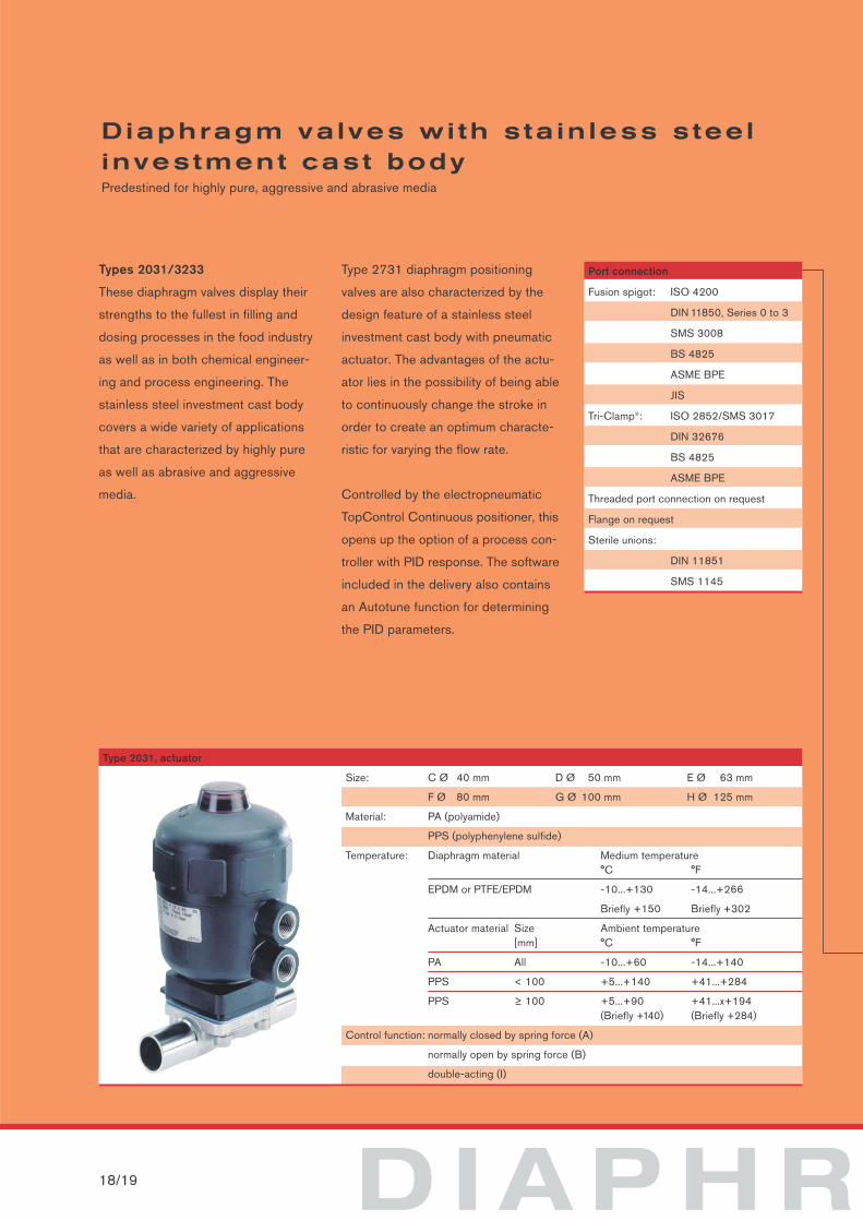
Diaphragm valves wi th s ta in less s tee linvestment cast bodyPredestined for highly pure, aggressive and abrasive media
Types 2031/3233
These diaphragm valves display their
strengths to the fullest in filling and
dosing processes in the food industry
as well as in both chemical engineer-
ing and process engineering. The
stainless steel investment cast body
covers a wide variety of applications
that are characterized by highly pure
as well as abrasive and aggressive
media.
Type 2731 diaphragm positioning
valves are also characterized by the
design feature of a stainless steel
investment cast body with pneumatic
actuator. The advantages of the actu-
ator lies in the possibility of being able
to continuously change the stroke in
order to create an optimum characte-
ristic for varying the flow rate.
Controlled by the electropneumatic
TopControl Continuous positioner, this
opens up the option of a process con-
troller with PID response. The software
included in the delivery also contains
an Autotune function for determining
the PID parameters.
Port connection
Fusion spigot: ISO 4200
DIN 11850, Series 0 to 3
SMS 3008
BS 4825
ASME BPE
JIS
Tri-Clamp®: ISO 2852/SMS 3017
DIN 32676
BS 4825
ASME BPE
Threaded port connection on request
Flange on request
Sterile unions:
DIN 11851
SMS 1145
Size: C Ø 40 mm D Ø 50 mm E Ø 63 mm
F Ø 80 mm G Ø 100 mm H Ø 125 mm
Material: PA (polyamide)
PPS (polyphenylene sulfide)
Temperature: Diaphragm material Medium temperature °C °F
EPDM or PTFE/EPDM -10...+130 -14...+266
Briefly +150 Briefly +302
Actuator material Size Ambient temperature [mm] °C °F
PA All -10...+60 -14...+140
PPS < 100 +5...+140 +41...+284
PPS ≥ 100 +5...+90 +41...x+194(Briefly +140) (Briefly +284)
Control function: normally closed by spring force (A)
normally open by spring force (B)
double-acting (I)
Type 2031, actuator
A G M VA LV E S
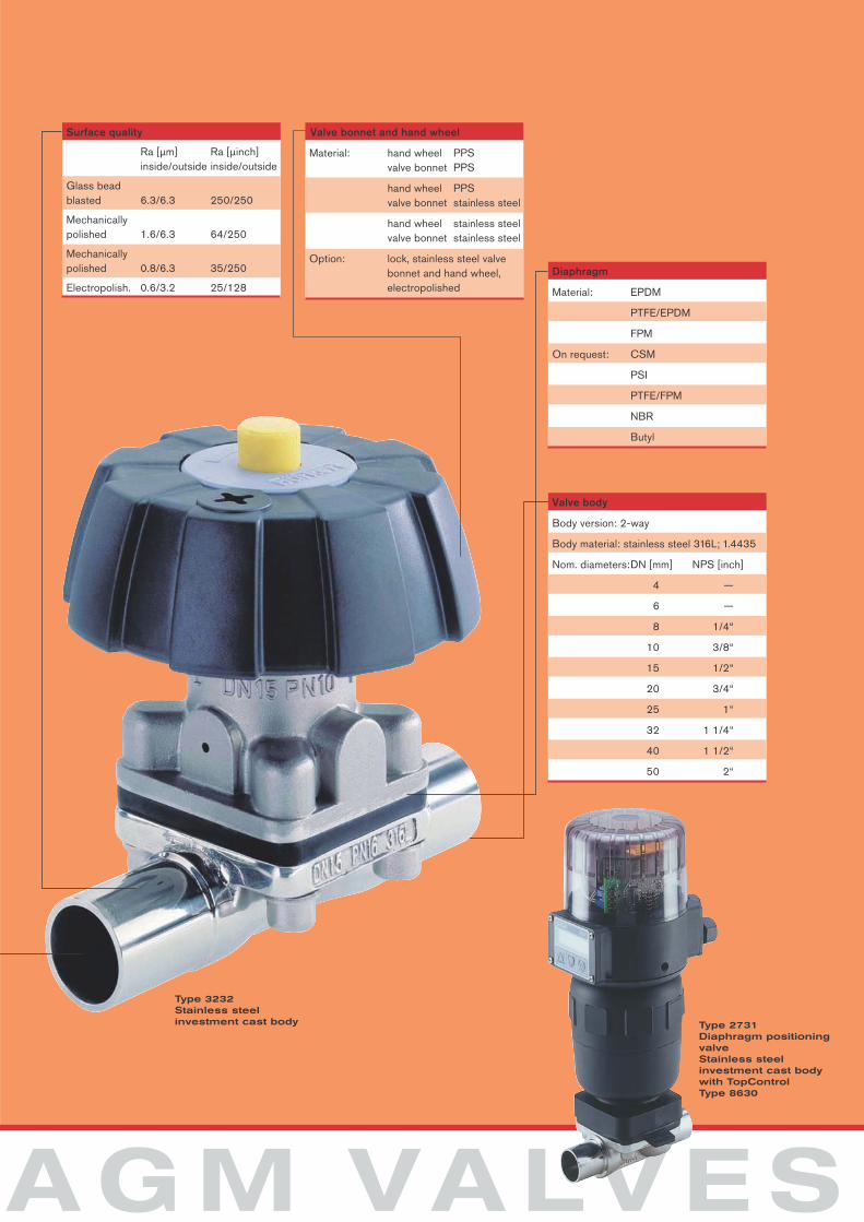
Surface quality
Ra [µm] Ra [µinch] inside/outside inside/outside
Glass beadblasted 6.3/6.3 250/250
Mechanically polished 1.6/6.3 64/250
Mechanically polished 0.8/6.3 35/250
Electropolish. 0.6/3.2 25/128
Material: hand wheel PPSvalve bonnet PPS
hand wheel PPSvalve bonnet stainless steel
hand wheel stainless steelvalve bonnet stainless steel
Option: lock, stainless steel valvebonnet and hand wheel,electropolished
Valve bonnet and hand wheel
Diaphragm
Material: EPDM
PTFE/EPDM
FPM
On request: CSM
PSI
PTFE/FPM
NBR
Butyl
Type 2731Diaphragm positioning valveStainless steel investment cast body with TopControl Type 8630
Valve body
Body version: 2-way
Body material: stainless steel 316L; 1.4435
Nom. diameters:DN [mm] NPS [inch]
4 —
6 —
8 1/4“
10 3/8“
15 1/2“
20 3/4“
25 1“
32 1 1/4“
40 1 1/2“
50 2“
Type 3232Stainless steel investment cast body
D I A P H R20/21
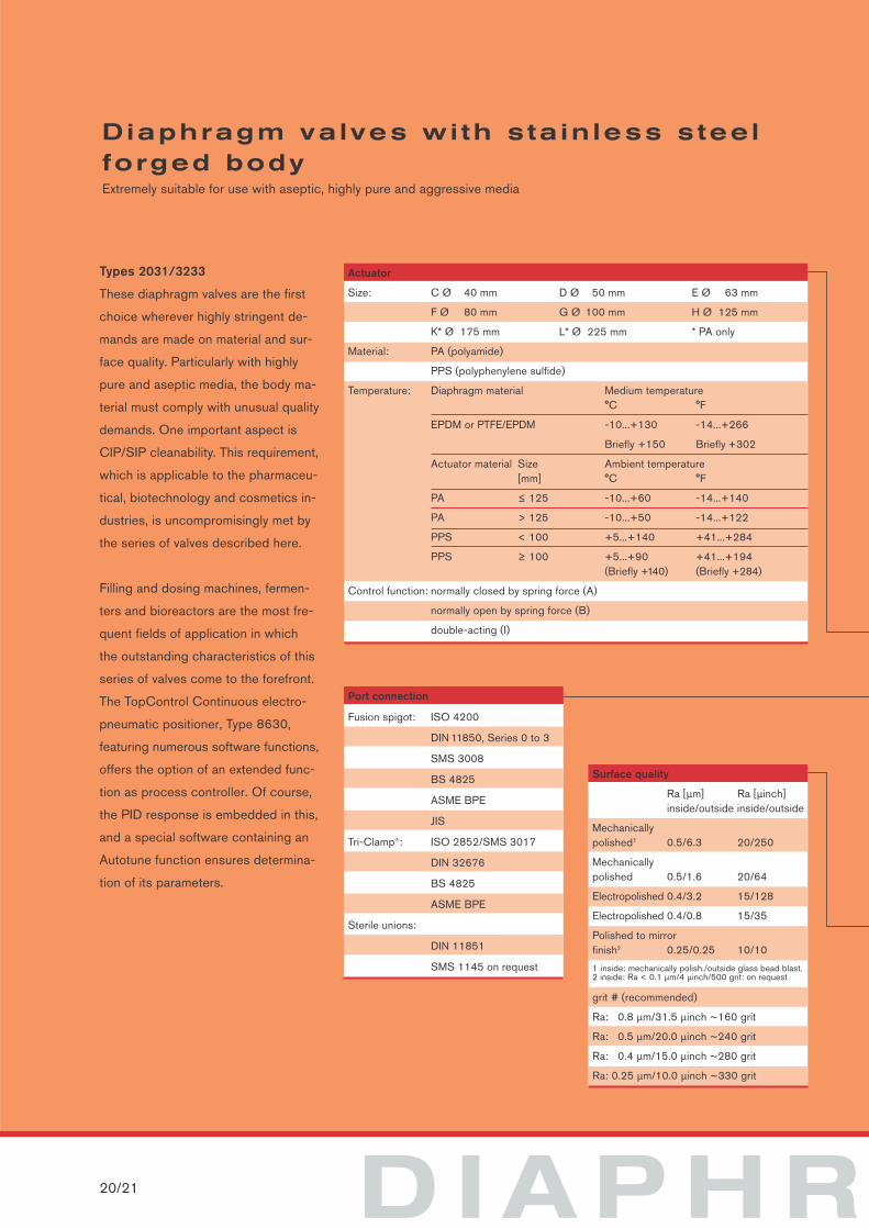
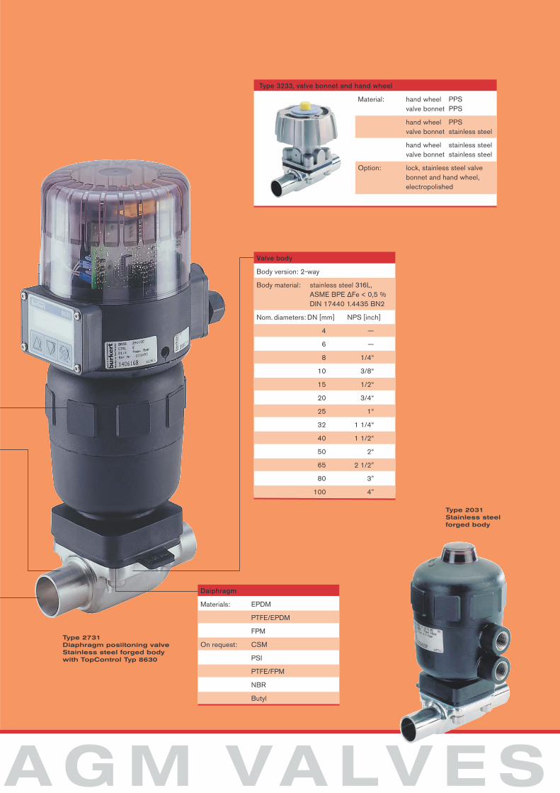
Diaphragm valves wi th s ta in less s tee lforged bodyExtremely suitable for use with aseptic, highly pure and aggressive media
Types 2031/3233
These diaphragm valves are the first
choice wherever highly stringent de-
mands are made on material and sur-
face quality. Particularly with highly
pure and aseptic media, the body ma-
terial must comply with unusual quality
demands. One important aspect is
CIP/SIP cleanability. This requirement,
which is applicable to the pharmaceu-
tical, biotechnology and cosmetics in-
dustries, is uncompromisingly met by
the series of valves described here.
Filling and dosing machines, fermen-
ters and bioreactors are the most fre-
quent fields of application in which
the outstanding characteristics of this
series of valves come to the forefront.
The TopControl Continuous electro-
pneumatic positioner, Type 8630,
featuring numerous software functions,
offers the option of an extended func-
tion as process controller. Of course,
the PID response is embedded in this,
and a special software containing an
Autotune function ensures determina-
tion of its parameters.
Surface quality
Ra [µm] Ra [µinch] inside/outside inside/outside
Mechanically polished1 0.5/6.3 20/250
Mechanicallypolished 0.5/1.6 20/64
Electropolished 0.4/3.2 15/128
Electropolished 0.4/0.8 15/35
Polished to mirrorfinish2 0.25/0.25 10/10
1 inside: mechanically polish./outside glass bead blast.2 inside: Ra < 0.1 µm/4 µinch/500 grit: on request
grit # (recommended)
Ra: 0.8 µm/31.5 µinch ~160 grit
Ra: 0.5 µm/20.0 µinch ~240 grit
Ra: 0.4 µm/15.0 µinch ~280 grit
Ra: 0.25 µm/10.0 µinch ~330 grit
Actuator
Size: C Ø 40 mm D Ø 50 mm E Ø 63 mm
F Ø 80 mm G Ø 100 mm H Ø 125 mm
K* Ø 175 mm L* Ø 225 mm * PA only
Material: PA (polyamide)
PPS (polyphenylene sulfide)
Temperature: Diaphragm material Medium temperature °C °F
EPDM or PTFE/EPDM -10...+130 -14...+266
Briefly +150 Briefly +302
Actuator material Size Ambient temperature [mm] °C °F
PA ≤ 125 -10...+60 -14...+140
PA > 125 -10...+50 -14...+122
PPS < 100 +5...+140 +41...+284
PPS ≥ 100 +5...+90 +41...+194(Briefly +140) (Briefly +284)
Control function: normally closed by spring force (A)
normally open by spring force (B)
double-acting (I)
Port connection
Fusion spigot: ISO 4200
DIN 11850, Series 0 to 3
SMS 3008
BS 4825
ASME BPE
JIS
Tri-Clamp®: ISO 2852/SMS 3017
DIN 32676
BS 4825
ASME BPE
Sterile unions:
DIN 11851
SMS 1145 on request
A G M VA LV E S
Valve body
Body version: 2-way
Body material: stainless steel 316L,ASME BPE ∆Fe < 0,5 %DIN 17440 1.4435 BN2
Nom. diameters: DN [mm] NPS [inch]
4 —
6 —
8 1/4“
10 3/8“
15 1/2“
20 3/4“
25 1“
32 1 1/4“
40 1 1/2“
50 2“
65 2 1/2”
80 3”
100 4”
Material: hand wheel PPSvalve bonnet PPS
hand wheel PPSvalve bonnet stainless steel
hand wheel stainless steelvalve bonnet stainless steel
Option: lock, stainless steel valvebonnet and hand wheel,electropolished
Type 3233, valve bonnet and hand wheel
Daiphragm
Materials: EPDM
PTFE/EPDM
FPM
On request: CSM
PSI
PTFE/FPM
NBR
Butyl
Type 2031Stainless steel forged body
Type 2731Diaphragm posiitoning valveStainless steel forged bodywith TopControl Typ 8630
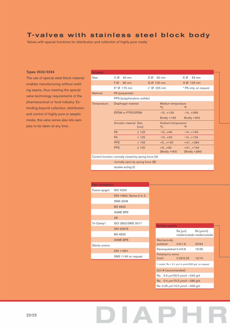
D I A P H R22/23
T-va lves wi th s ta in less s tee l b lock bodyValves with special functions for distribution and collection of highly pure media
Types 2032/3234
The use of special steel block material
enables manufacturing without weld-
ing seams, thus meeting the special
valve technology requirements of the
pharmaceutical or food industry. Ex-
tending beyond collection, distribution
and control of highly pure or aseptic
media, this valve series also lets sam-
ples to be taken at any time.
Surface quality
Ra [µm] Ra [µinch] inside/outside inside/outside
Mechanically polished 0.5/1.6 20/64
Electropolished 0.4/0.8 15/35
Polished to mirrorfinish1 0.25/0.25 10/10
1 inside: Ra < 0.1 µm/ 4 µinch/500 grit: on request
Grit # (recommended)
Ra: 0.5 µm/20.0 µinch ~240 grit
Ra: 0.4 µm/15.0 µinch ~280 grit
Ra: 0.25 µm/10.0 µinch ~330 grit
Actuator
Size: C Ø 40 mm D Ø 50 mm E Ø 63 mm
F Ø 80 mm G Ø 100 mm H Ø 125 mm
K* Ø 175 mm L* Ø 225 mm * PA only, on request
Material: PA (polyamide)
PPS (polyphenylene sulfide)
Temperature: Diaphragm material Medium temperature°C °F
EPDM or PTFE/EPDM -10...+130 -14...+266
Briefly +150 Briefly +302
Actuator material Size Ambient temperature [mm] °C °F
PA ≤ 125 -10...+60 -14...+140
PA > 125 -10...+50 -14...+122
PPS < 100 +5...+140 +41...+284
PPS ≥ 100 +5...+90 +41...+194(Briefly +140) (Briefly +284)
Control function: normally closed by spring force (A)
normally open by spring force (B)
double-acting (I)
Port connection
Fusion spigot: ISO 4200
DIN 11850, Series 0 to 3
SMS 3008
BS 4825
ASME BPE
JIS
Tri-Clamp®: ISO 2852/SMS 3017
DIN 32676
BS 4825
ASME BPE
Sterile unions:
DIN 11851
SMS 1145 on request
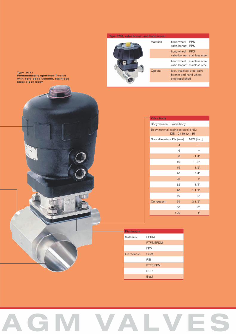
A G M VA LV E S
Material: hand wheel PPSvalve bonnet PPS
hand wheel PPSvalve bonnet stainless steel
hand wheel stainless steelvalve bonnet stainless steel
Option: lock, stainless steel valvebonnet and hand wheel, electropolished
Type 3234, valve bonnet and hand wheel
Diaphragm
Materials: EPDM
PTFE/EPDM
FPM
On request: CSM
PSI
PTFE/FPM
NBR
Butyl
Type 2032Pneumatically operated T-valvewith zero dead volume, stainlesssteel block body
Valve body
Body version: T-valve body
Body material: stainless steel 316L;DIN 17440 1.4435
Nom. diameters: DN [mm] NPS [inch]
4 —
6 —
8 1/4“
10 3/8“
15 1/2“
20 3/4“
25 1“
32 1 1/4“
40 1 1/2“
50 2“
On request: 65 2 1/2”
80 3”
100 4”
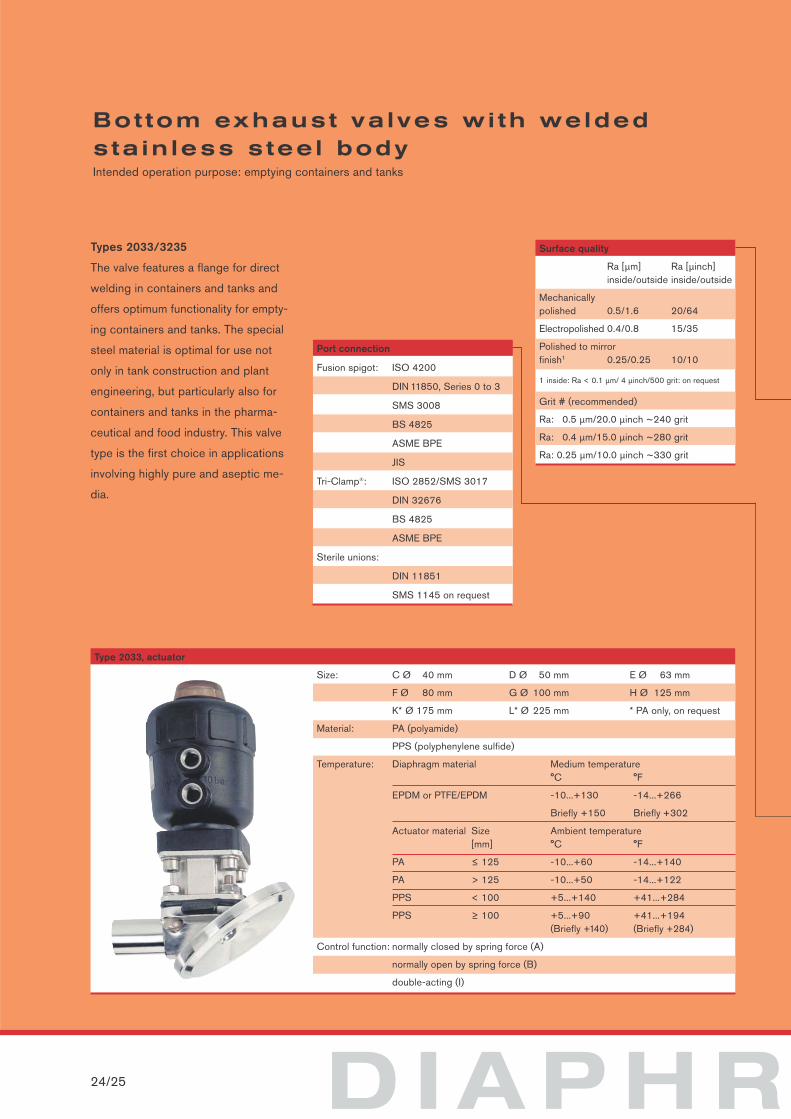
D I A P H R24/25
Bot tom exhaust va lves wi th weldedsta in less s tee l bodyIntended operation purpose: emptying containers and tanks
Size: C Ø 40 mm D Ø 50 mm E Ø 63 mm
F Ø 80 mm G Ø 100 mm H Ø 125 mm
K* Ø 175 mm L* Ø 225 mm * PA only, on request
Material: PA (polyamide)
PPS (polyphenylene sulfide)
Temperature: Diaphragm material Medium temperature °C °F
EPDM or PTFE/EPDM -10...+130 -14...+266
Briefly +150 Briefly +302
Actuator material Size Ambient temperature [mm] °C °F
PA ≤ 125 -10...+60 -14...+140
PA > 125 -10...+50 -14...+122
PPS < 100 +5...+140 +41...+284
PPS ≥ 100 +5...+90 +41...+194(Briefly +140) (Briefly +284)
Control function: normally closed by spring force (A)
normally open by spring force (B)
double-acting (I)
Type 2033, actuator
Surface quality
Ra [µm] Ra [µinch] inside/outside inside/outside
Mechanically polished 0.5/1.6 20/64
Electropolished 0.4/0.8 15/35
Polished to mirrorfinish1 0.25/0.25 10/10
1 inside: Ra < 0.1 µm/ 4 µinch/500 grit: on request
Grit # (recommended)
Ra: 0.5 µm/20.0 µinch ~240 grit
Ra: 0.4 µm/15.0 µinch ~280 grit
Ra: 0.25 µm/10.0 µinch ~330 grit
Types 2033/3235
The valve features a flange for direct
welding in containers and tanks and
offers optimum functionality for empty-
ing containers and tanks. The special
steel material is optimal for use not
only in tank construction and plant
engineering, but particularly also for
containers and tanks in the pharma-
ceutical and food industry. This valve
type is the first choice in applications
involving highly pure and aseptic me-
dia.
Port connection
Fusion spigot: ISO 4200
DIN 11850, Series 0 to 3
SMS 3008
BS 4825
ASME BPE
JIS
Tri-Clamp®: ISO 2852/SMS 3017
DIN 32676
BS 4825
ASME BPE
Sterile unions:
DIN 11851
SMS 1145 on request
A G M VA LV E S
Material: hand wheel PPSvalve bonnet PPS
hand wheel PPSvalve bonnet stainless steel
hand wheel stainless steelvalve bonnet stainless steel
Option: lock, stainless steel valvebonnet and hand wheel, electropolished
Valve bonnet and hand wheel
Diaphragms
Material: EPDM
PTFE/EPDM
FPM
On request: CSM
PSI
PTFE/FPM
NBR
Butyl
Valve body
Body version: stainless steel body, welded
Body material: stainless steel 316L,ASME BPE ∆Fe < 0.5 %DIN 17440 1.4435 BN2
Nom. diameters: DN [mm] NPS [inch]
8 1/4“
15 1/2“
20 3/4“
25 1“
32 1 1/4“
40 1 1/2“
50 2“
65 2 1/2“
On request: 80 3”
100 4”
Type 3235Manually operatedbottom exhaust valve
SPECIA
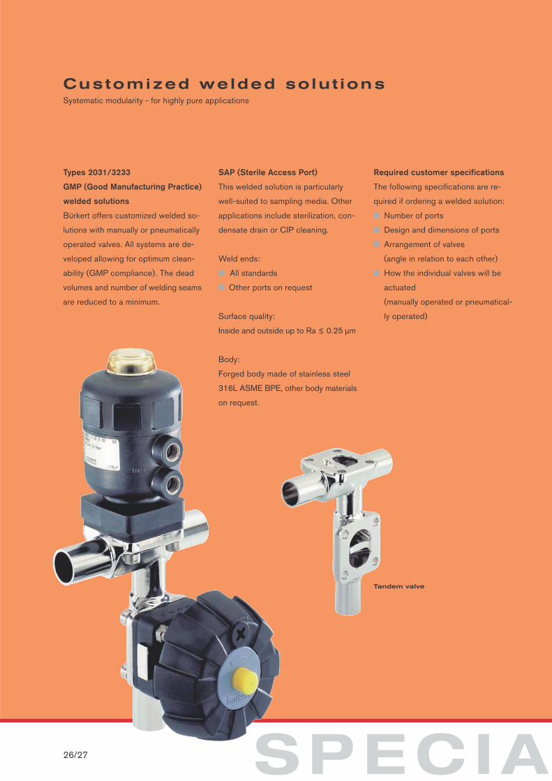
Types 2031/3233
GMP (Good Manufacturing Practice)
welded solutions
Bürkert offers customized welded so-
lutions with manually or pneumatically
operated valves. All systems are de-
veloped allowing for optimum clean-
ability (GMP compliance). The dead
volumes and number of welding seams
are reduced to a minimum.
SAP (Sterile Access Port)
This welded solution is particularly
well-suited to sampling media. Other
applications include sterilization, con-
densate drain or CIP cleaning.
Weld ends:
■ All standards
■ Other ports on request
Surface quality:
Inside and outside up to Ra ≤ 0.25 µm
Body:
Forged body made of stainless steel
316L ASME BPE, other body materials
on request.
Required customer specifications
The following specifications are re-
quired if ordering a welded solution:
■ Number of ports
■ Design and dimensions of ports
■ Arrangement of valves
(angle in relation to each other)
■ How the individual valves will be
actuated
(manually operated or pneumatical-
ly operated)
26/27
Customized welded solut ionsSystematic modularity - for highly pure applications
Tandem valve
L SOLUTIONS
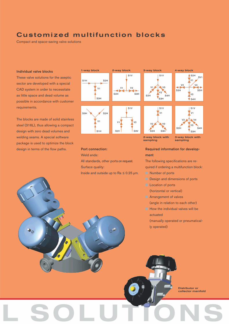
Individual valve blocks
These valve solutions for the aseptic
sector are developed with a special
CAD system in order to necessitate
as little space and dead volume as
possible in accordance with customer
requirements.
The blocks are made of solid stainless
steel (316L), thus allowing a compact
design with zero dead volumes and
welding seams. A special software
package is used to optimize the block
design in terms of the flow paths. Port connection:
Weld ends:
All standards, other ports on request.
Surface quality:
Inside and outside up to Ra ≤ 0.25 µm.
Required information for develop-
ment
The following specifications are re-
quired if ordering a multifunction block:
■ Number of ports
■ Design and dimensions of ports
■ Location of ports
(horizontal or vertical)
■ Arrangement of valves
(angle in relation to each other)
■ How the individual valves will be
actuated
(manually operated or pneumatical-
ly operated)
Customized mul t i funct ion b locksCompact and space-saving valve solutions
V1
S1H S2H
S3H
V2V1
S1V
S3HS2H
V2V1
S1V
S3VS2V
V3V1
S1V
S4HS2H
V2 V3
V1
S1V
S3HS2H
V1
S3H S2H
S1H
S3H
V2
V2 V4
S2HSV1
S3H S5H
V2 V4
V1
S1V
S4HS2H
S4H
V3
V1
V3
S3H
1-way block 2-way block 3-way block 4-way block
2-way block withsampling
3-way block withsampling
Distributor or collector manifold
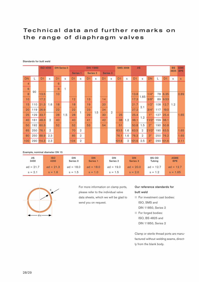
Example, nominal diameter DN 15
Standards for butt weld
For more information on clamp ports,
please refer to the individual valve
data sheets, which we will be glad to
send you on request.
Our reference standards for
butt weld
■ For investment cast bodies:
ISO, SMS and
DIN 11850, Series 2
■ For forged bodies:
ISO, BS 4825 and
DIN 11850, Series 2
Clamp or sterile thread ports are manu-
factured without welding seams, direct-
ly from the blank body.
JIS ISO DIN DIN DIN DIN BS-OD ASME3459 4200 Series 0 Series 1 Series 2 Series 3 Tubing BPE
ød = 21.7 ød = 21.3 ød = 18.0 ød = 18.0 ød = 19.0 ød = 20.0 ød = 12.7 ød = 12.7
s = 2.1 s = 1.6 s = 1.5 s = 1.0 s = 1.5 s = 2.0 s = 1.2 s = 1.65
DN L D1 s D1 s D1 s D1 s D1 s D1 s D1 s DN L D1 s s
4 6
6 8 1
8 13.5 10 13.81.65
1/4“ 78 6.35 0.89
10 17.2 12 13 14 17.3 3/8“ 89 9.53
15 110 21.3 1.6 18 18 19 20 21.72.1
1/2“ 108 12.7 1.2
20 119 26.9 22 22 23 24 27.2 3/4“ 117 19.0
25 129 33.7 28 1.5 28 29 30 25 25.41.2
1“ 127 25.4 1.65
40 161 48.3 2 40 40 41 42 38 1.2 38.1 11/2“ 159 38.1
50 192 60.3 52 52 53 54 51 50.8 1.5 2“ 190 50.8
65 250 76.1 2 70 2 63.5 1.6 63.5 2 21/2“ 190 63.5 1.65
80 250 88.9 2.3 85 2 76.1 1.6 76.3 2 3“ 250 76.2 1.65
100 290 114.3 2.3 104 2 101.6 2 101.6 2.5 4“ 290 101.6 2.11
Technica l data and fur ther remarks onthe range of d iaphragm valves
28/29
ISO 4200 DIN 11850 SMS 3008 JIS BS4825
ASMEBPE
Series 1
90
Series 2 Series 3
DIN Series 0
1 1.5 2
Ø d
S
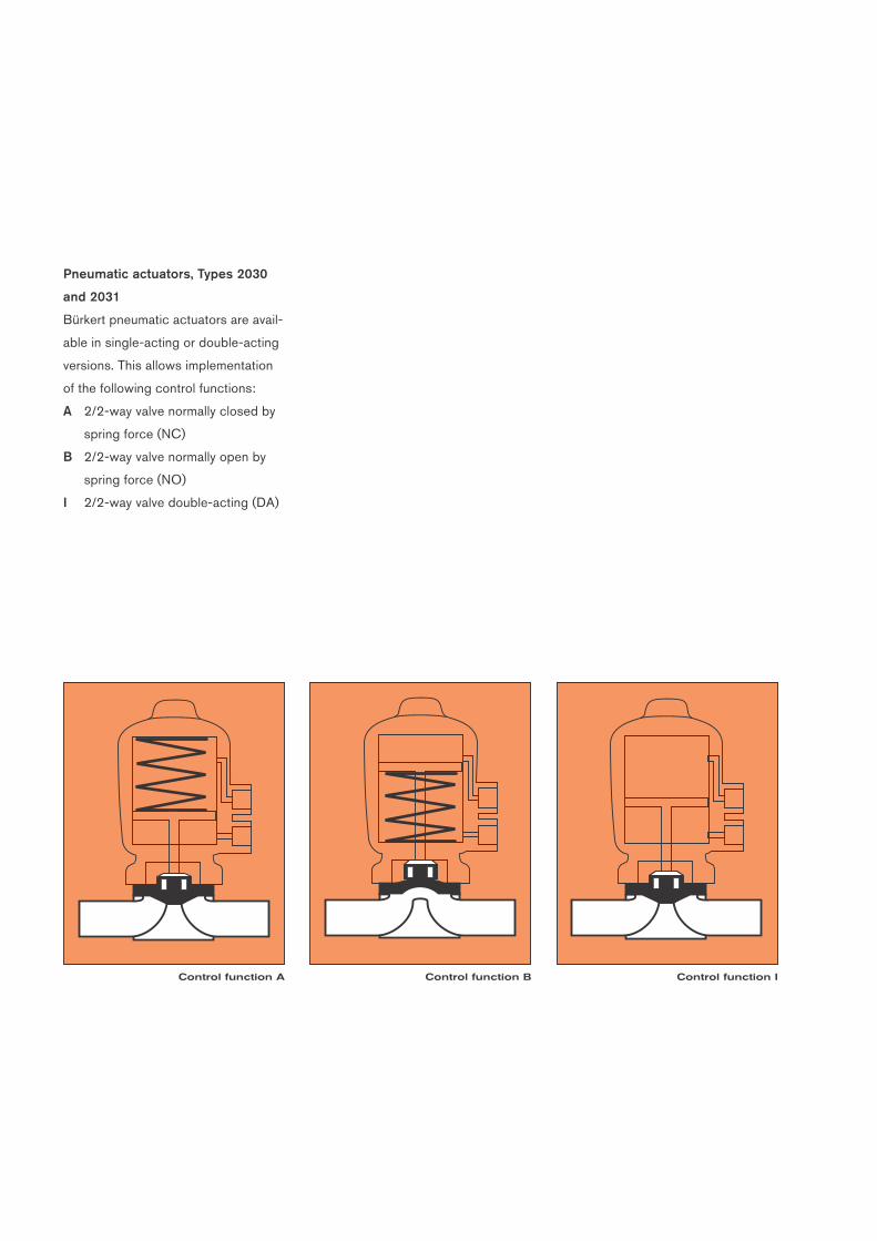
Control function A Control function B Control function I
Pneumatic actuators, Types 2030
and 2031
Bürkert pneumatic actuators are avail-
able in single-acting or double-acting
versions. This allows implementation
of the following control functions:
A 2/2-way valve normally closed by
spring force (NC)
B 2/2-way valve normally open by
spring force (NO)
I 2/2-way valve double-acting (DA)
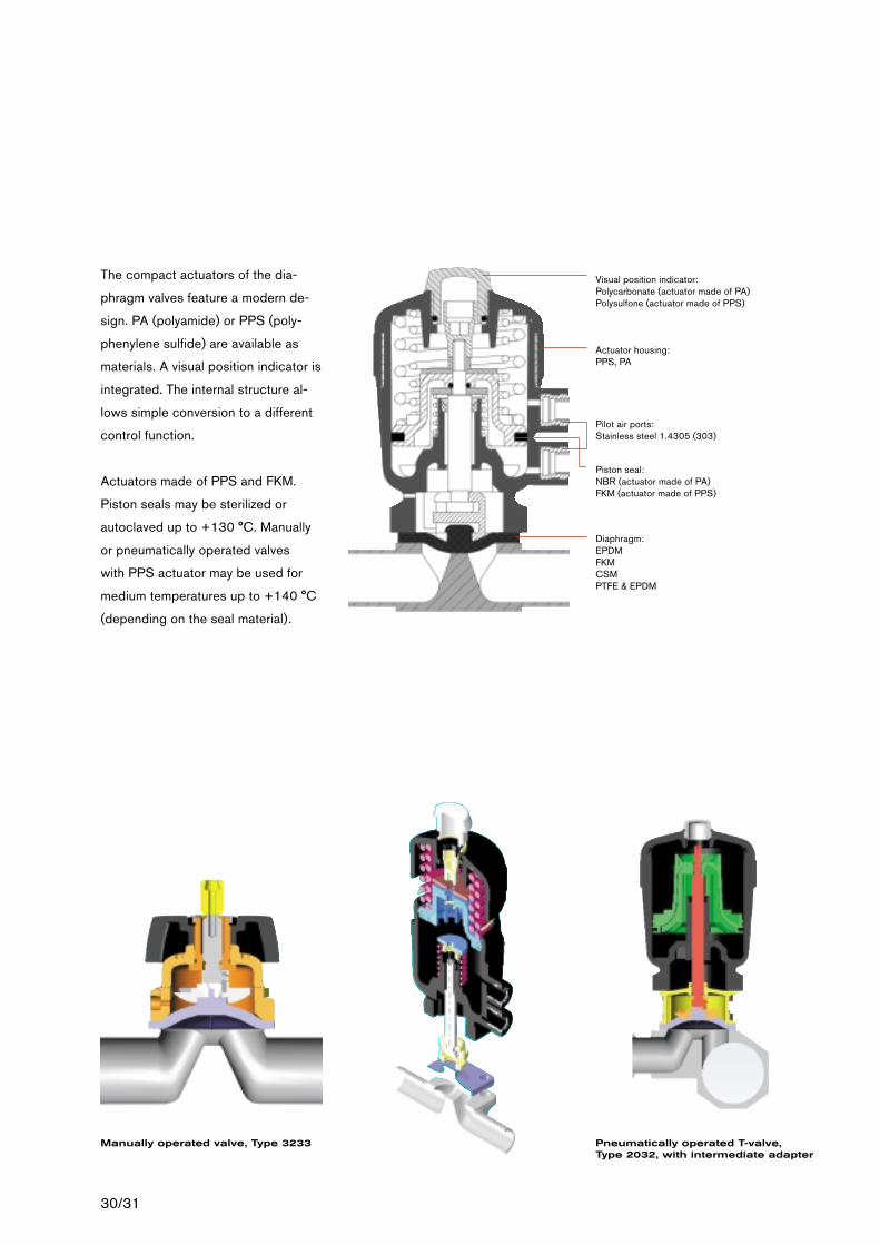
Pilot air ports:Stainless steel 1.4305 (303)
30/31
The compact actuators of the dia-
phragm valves feature a modern de-
sign. PA (polyamide) or PPS (poly-
phenylene sulfide) are available as
materials. A visual position indicator is
integrated. The internal structure al-
lows simple conversion to a different
control function.
Actuators made of PPS and FKM.
Piston seals may be sterilized or
autoclaved up to +130 °C. Manually
or pneumatically operated valves
with PPS actuator may be used for
medium temperatures up to +140 °C
(depending on the seal material).
Manually operated valve, Type 3233 Pneumatically operated T-valve, Type 2032, with intermediate adapter
Diaphragm: EPDMFKMCSMPTFE & EPDM
Actuator housing:PPS, PA
Piston seal: NBR (actuator made of PA) FKM (actuator made of PPS)
Visual position indicator:Polycarbonate (actuator made of PA)Polysulfone (actuator made of PPS)
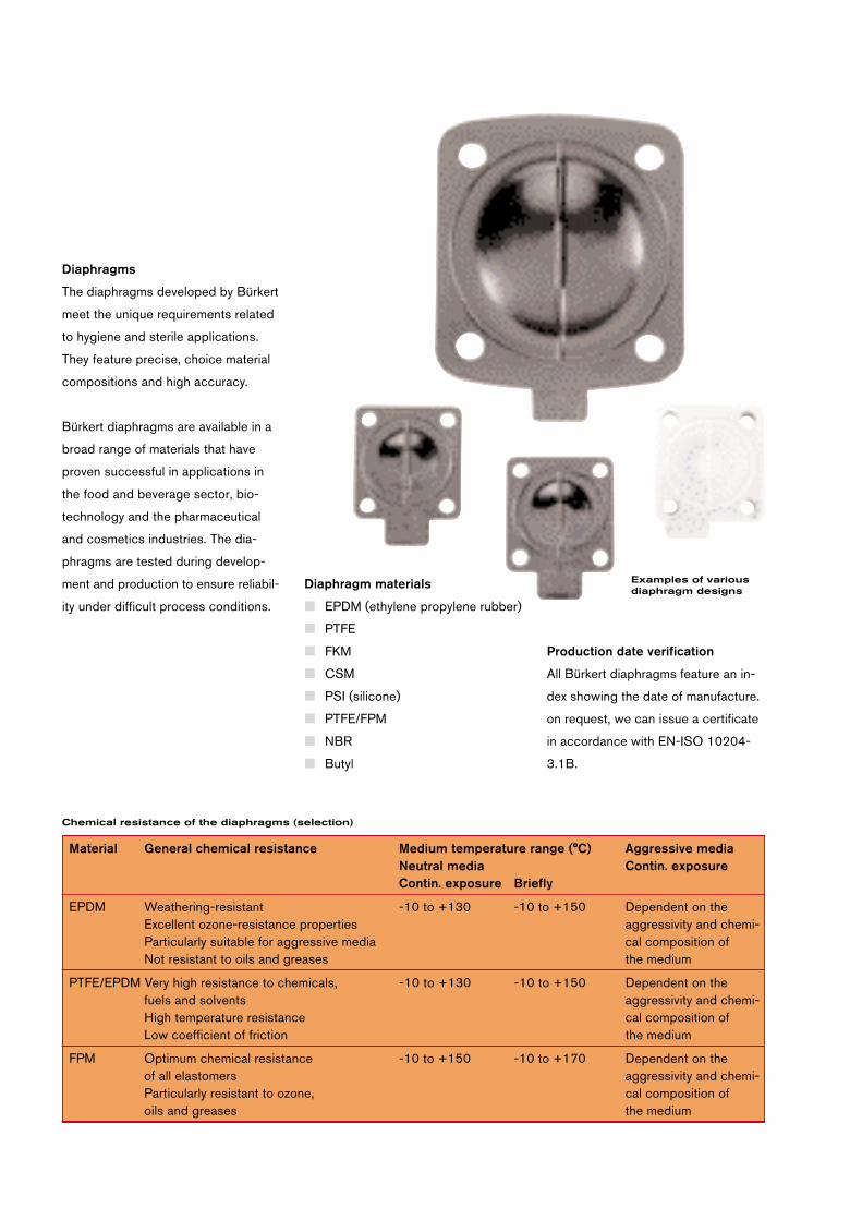
Diaphragm materials
■ EPDM (ethylene propylene rubber)
■ PTFE
■ FKM
■ CSM
■ PSI (silicone)
■ PTFE/FPM
■ NBR
■ Butyl
Production date verification
All Bürkert diaphragms feature an in-
dex showing the date of manufacture.
on request, we can issue a certificate
in accordance with EN-ISO 10204-
3.1B.
Diaphragms
The diaphragms developed by Bürkert
meet the unique requirements related
to hygiene and sterile applications.
They feature precise, choice material
compositions and high accuracy.
Bürkert diaphragms are available in a
broad range of materials that have
proven successful in applications in
the food and beverage sector, bio-
technology and the pharmaceutical
and cosmetics industries. The dia-
phragms are tested during develop-
ment and production to ensure reliabil-
ity under difficult process conditions.
Material General chemical resistance Medium temperature range (°C) Aggressive mediaNeutral media Contin. exposureContin. exposure Briefly
EPDM Weathering-resistant -10 to +130 -10 to +150 Dependent on the Excellent ozone-resistance properties aggressivity and chemi- Particularly suitable for aggressive media cal composition of Not resistant to oils and greases the medium
PTFE/EPDM Very high resistance to chemicals, -10 to +130 -10 to +150 Dependent on the fuels and solvents aggressivity and chemi-High temperature resistance cal composition ofLow coefficient of friction the medium
FPM Optimum chemical resistance -10 to +150 -10 to +170 Dependent on theof all elastomers aggressivity and chemi-Particularly resistant to ozone, cal composition of oils and greases the medium
Chemical resistance of the diaphragms (selection)
Examples of variousdiaphragm designs
32/33
Product benefits
■ The high-quality surfaces meet the
stringent requirements concerning
purity in the processes.
■ The surface quality is described by
the mean roughness index Ra.
Electropolishing
■ 50 % reduction of roughness by
smoothing the surface. This also
reduces the surface tension
■ Increase in corrosion resistance via
a high-chromium oxide layer as a
protective film
■ Optimization of cleanability and
sterilizability
■ Removal of contamination by lubri-
cants or grain particles
■ External appearance enhanced by
glossy surface
Surface qualities
Using the example of Type 2031/3233
with forged body
High surface quality
Owing to grinding or polishing, the
surface is free of shrink-holes, scoring
and other roughness phenomena and
free of impurities.
Low ferrite content
Virtually ferrite-free alloys prevent
contamination which may occur due
to the use of cast pipe sections.
Forged bodies
The key to hygiene is the high quality
of Bürkert forged bodies. They are
manufactured from stainless steel
DIN 17440 - 1.4435/ASME BPE
2002 316L or 1.4435 BN2
(with ferrite content < 0.5 %).
(low sulfur content)
A high surface quality is demanded,
particularly in the pharmaceutical and
biotechnology industries.
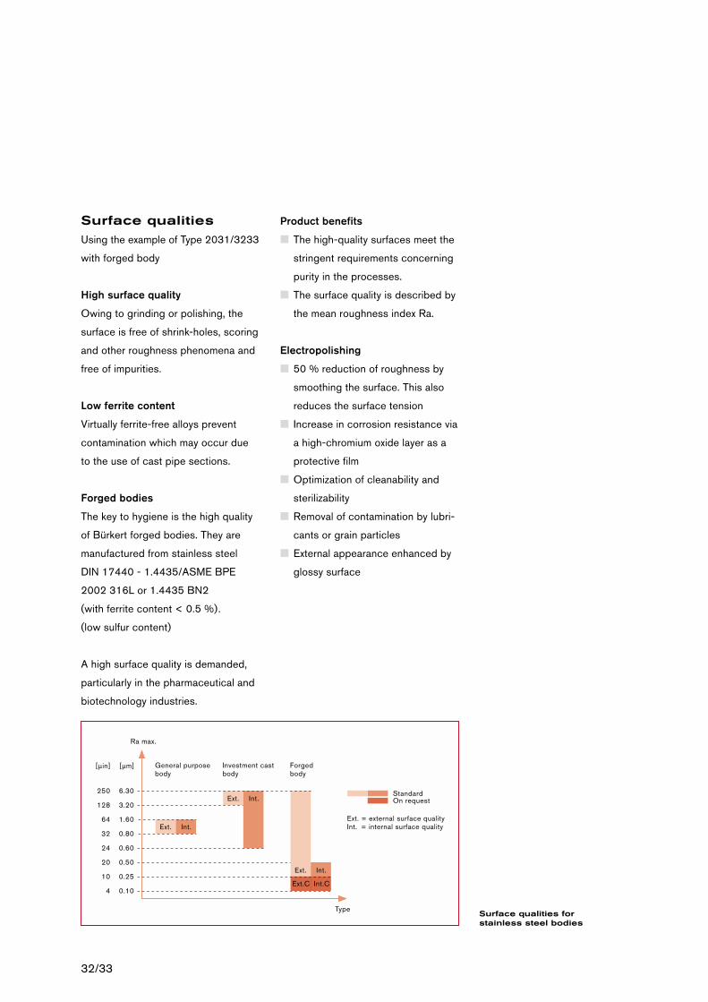
[µin]
250
128
64
32
24
20
10
4
[µm]
6.30
3.20
1.60
0.80
0.60
0.50
0.25
0.10
General purpose body
Investment cast body
Forged body
Type
Ra max.
Ext. Int.
Ext. Int.
Ext. Int.
Ext.C Int.C
StandardOn request
Ext. = external surface qualityInt. = internal surface quality
Surface qualities forstainless steel bodies
Valve installation
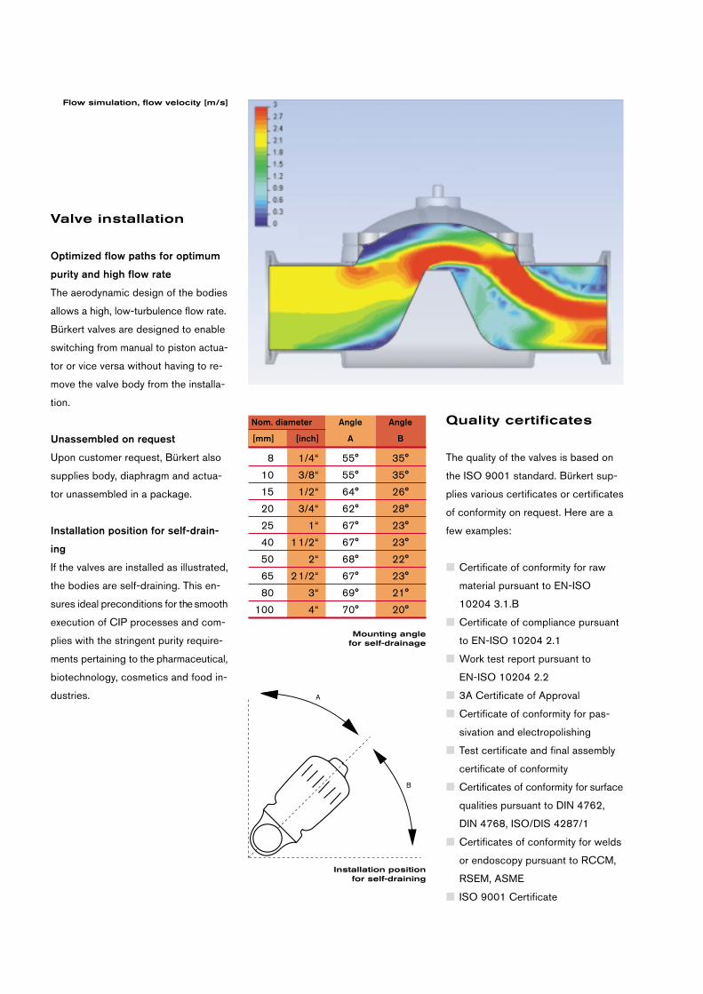
Optimized flow paths for optimum
purity and high flow rate
The aerodynamic design of the bodies
allows a high, low-turbulence flow rate.
Bürkert valves are designed to enable
switching from manual to piston actua-
tor or vice versa without having to re-
move the valve body from the installa-
tion.
Unassembled on request
Upon customer request, Bürkert also
supplies body, diaphragm and actua-
tor unassembled in a package.
Installation position for self-drain-
ing
If the valves are installed as illustrated,
the bodies are self-draining. This en-
sures ideal preconditions for the smooth
execution of CIP processes and com-
plies with the stringent purity require-
ments pertaining to the pharmaceutical,
biotechnology, cosmetics and food in-
dustries.
Flow simulation, flow velocity [m/s]
B
A
Nom. diameter Angle Angle
[mm] [inch] A B
8 1/4“ 55° 35°
10 3/8“ 55° 35°
15 1/2“ 64° 26°
20 3/4“ 62° 28°
25 1“ 67° 23°
40 11/2“ 67° 23°
50 2“ 68° 22°
65 21/2“ 67° 23°
80 3“ 69° 21°
100 4“ 70° 20°
Installation position for self-draining
Mounting angle for self-drainage
Quality certificates
The quality of the valves is based on
the ISO 9001 standard. Bürkert sup-
plies various certificates or certificates
of conformity on request. Here are a
few examples:
■ Certificate of conformity for raw
material pursuant to EN-ISO
10204 3.1.B
■ Certificate of compliance pursuant
to EN-ISO 10204 2.1
■ Work test report pursuant to
EN-ISO 10204 2.2
■ 3A Certificate of Approval
■ Certificate of conformity for pas-
sivation and electropolishing
■ Test certificate and final assembly
certificate of conformity
■ Certificates of conformity for surface
qualities pursuant to DIN 4762,
DIN 4768, ISO/DIS 4287/1
■ Certificates of conformity for welds
or endoscopy pursuant to RCCM,
RSEM, ASME
■ ISO 9001 Certificate
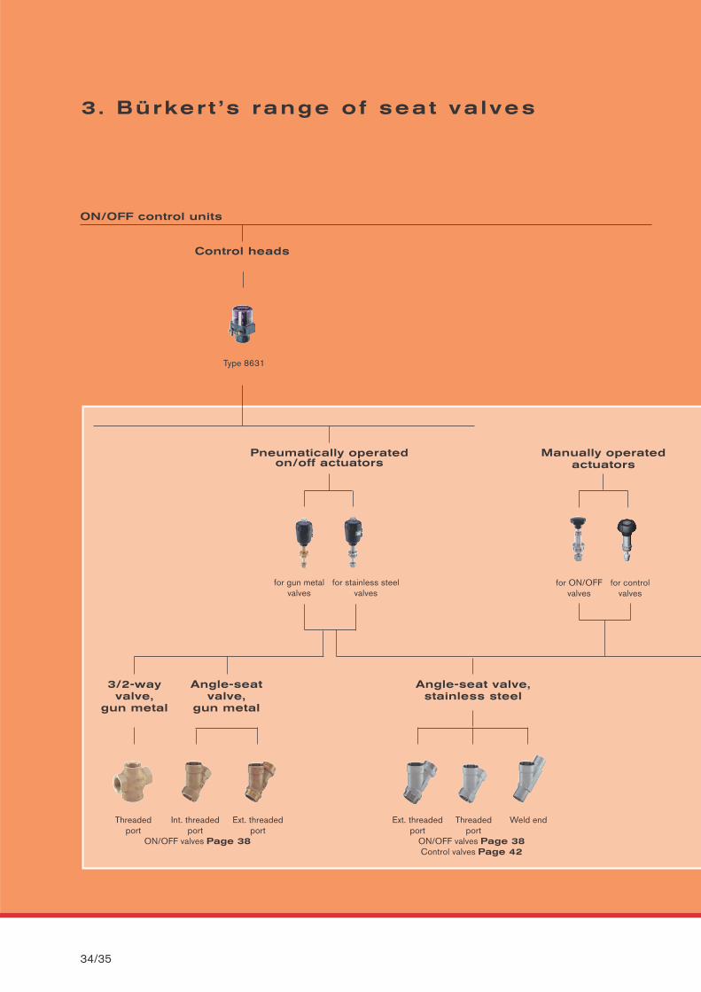
3. Bürker t ’s range of seat va lves
34/35
ON/OFF control units
Pneumatically operated on/off actuators
Control heads
Type 8631
for gun metal valves
for stainless steelvalves
Manually operated actuators
for ON/OFFvalves
for controlvalves
3/2-way valve,
gun metal
Angle-seatvalve,
gun metal
Threaded Int. threaded Ext. threadedport port port
ON/OFF valves Page 38
Angle-seat valve,stainless steel
Ext. threaded Threaded Weld endport port
ON/OFF valves Page 38Control valves Page 42
SEAT VALVES
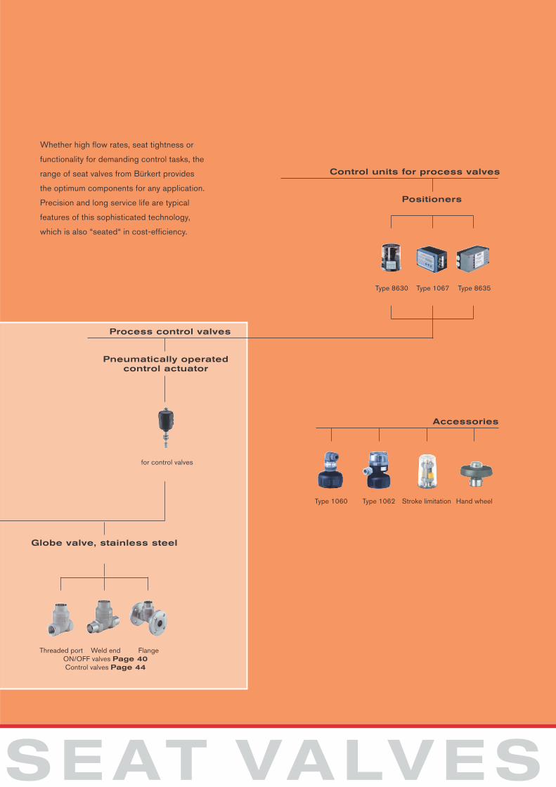
Pneumatically operatedcontrol actuator
Control units for process valves
Process control valves
for control valves
Positioners
Type 8630 Type 1067 Type 8635
Accessories
Type 1060 Type 1062 Stroke limitation Hand wheel
Globe valve, stainless steel
Threaded port Weld end FlangeON/OFF valves Page 40Control valves Page 44
Whether high flow rates, seat tightness or
functionality for demanding control tasks, the
range of seat valves from Bürkert provides
the optimum components for any application.
Precision and long service life are typical
features of this sophisticated technology,
which is also “seated“ in cost-efficiency.
36/37
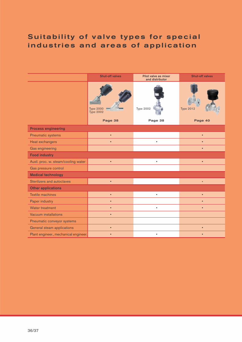
Shut-off valves Pilot valve as mixerand distributor
Shut-off valves
Type 2000Type 2002
Type 2002 Type 2012
Page 38 Page 38 Page 40
Su i tab i l i t y o f va lve types for specia l industr ies and areas of appl icat ion
Process engineering
Pneumatic systems • •
Heat exchangers • • •
Gas engineering •
Food industry
Auxil. proc. w. steam/cooling water • • •
Gas pressure control
Medical technology
Sterilizers and autoclaves • •
Other applications
Textile machines • • •
Paper industry • •
Water treatment • • •
Vacuum installations •
Pneumatic conveyor systems
General steam applications • •
Plant engineer., mechanical engineer. • • •
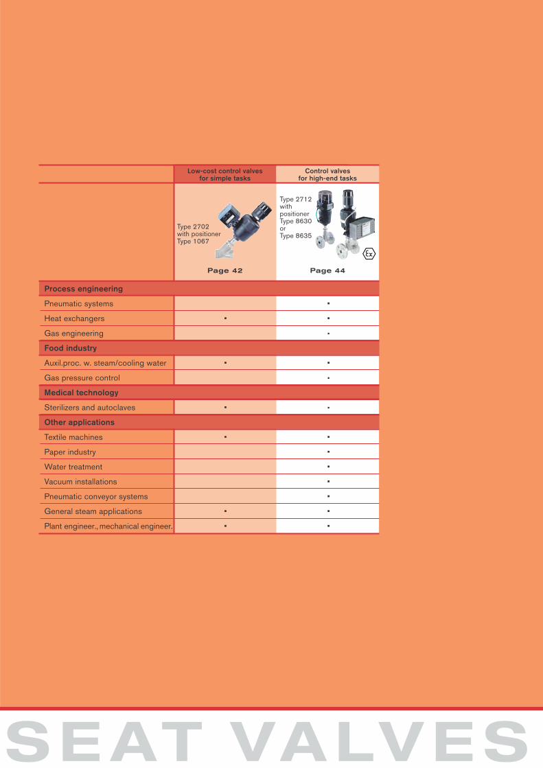
Low-cost control valves for simple tasks
Control valves for high-end tasks
Type 2702with positionerType 1067
Type 2712withpositionerType 8630 or Type 8635
Page 42 Page 44
SEAT VALVES
Process engineering
Pneumatic systems •
Heat exchangers • •
Gas engineering •
Food industry
Auxil.proc. w. steam/cooling water • •
Gas pressure control •
Medical technology
Sterilizers and autoclaves • •
Other applications
Textile machines • •
Paper industry •
Water treatment •
Vacuum installations •
Pneumatic conveyor systems •
General steam applications • •
Plant engineer., mechanical engineer. • •
38/39
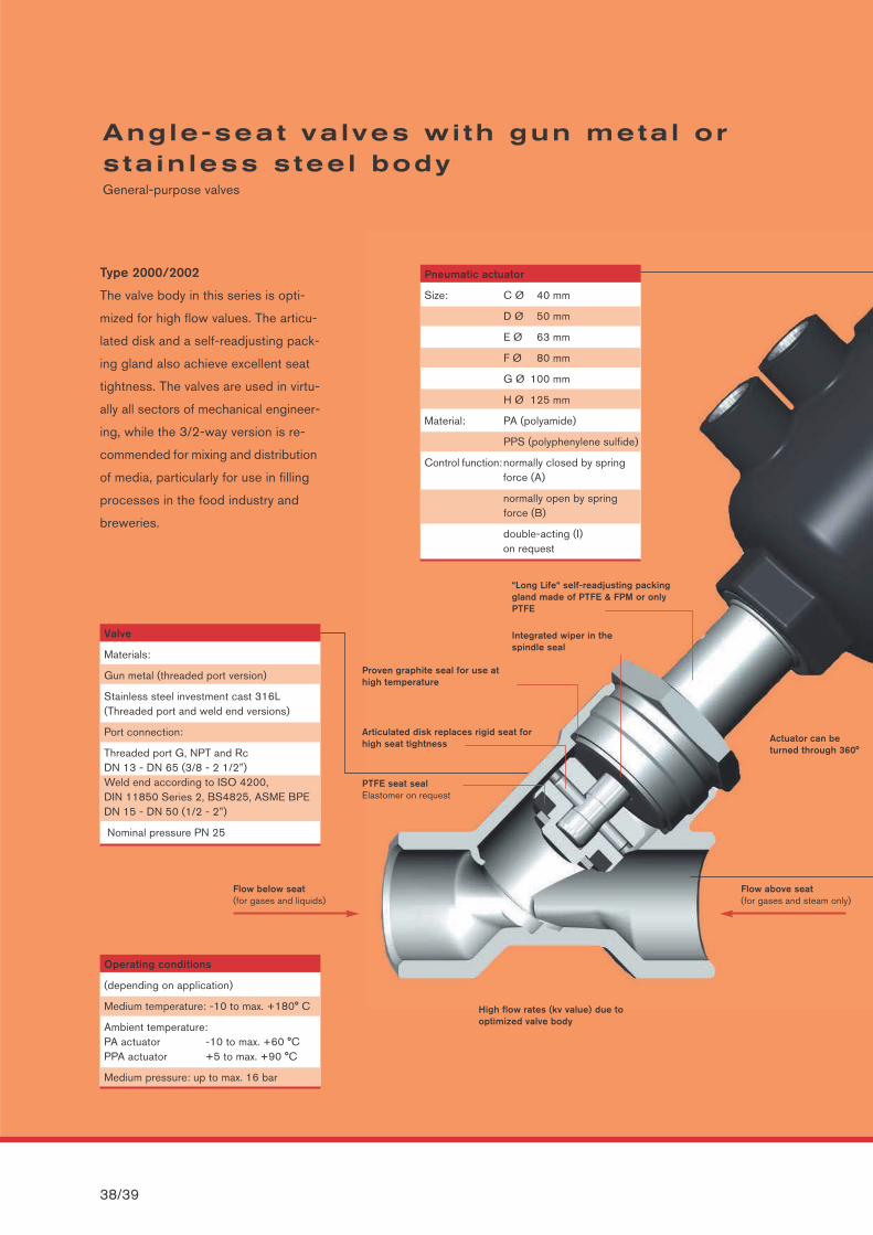
Angle-seat va lves wi th gun meta l ors ta in less s tee l body General-purpose valves
Operating conditions
(depending on application)
Medium temperature: -10 to max. +180° C
Ambient temperature:PA actuator -10 to max. +60 °CPPA actuator +5 to max. +90 °C
Medium pressure: up to max. 16 bar
Valve
Materials:
Gun metal (threaded port version)
Stainless steel investment cast 316L(Threaded port and weld end versions)
Port connection:
Threaded port G, NPT and Rc DN 13 - DN 65 (3/8 - 2 1/2”)Weld end according to ISO 4200, DIN 11850 Series 2, BS4825, ASME BPE DN 15 - DN 50 (1/2 - 2”)
Nominal pressure PN 25
Type 2000/2002
The valve body in this series is opti-
mized for high flow values. The articu-
lated disk and a self-readjusting pack-
ing gland also achieve excellent seat
tightness. The valves are used in virtu-
ally all sectors of mechanical engineer-
ing, while the 3/2-way version is re-
commended for mixing and distribution
of media, particularly for use in filling
processes in the food industry and
breweries.
Pneumatic actuator
Size: C Ø 40 mm
D Ø 50 mm
E Ø 63 mm
F Ø 80 mm
G Ø 100 mm
H Ø 125 mm
Material: PA (polyamide)
PPS (polyphenylene sulfide)
Control function:normally closed by springforce (A)
normally open by spring force (B)
double-acting (I) on request
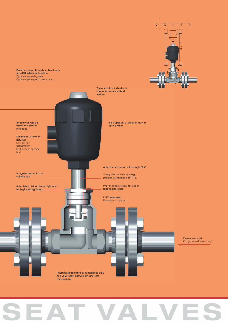
Actuator can be turned through 360°
Proven graphite seal for use athigh temperature
Articulated disk replaces rigid seat forhigh seat tightness
PTFE seat sealElastomer on request
Flow below seat (for gases and liquids)
High flow rates (kv value) due tooptimized valve body
“Long Life“ self-readjusting packinggland made of PTFE & FPM or onlyPTFE
Integrated wiper in thespindle seal
Flow above seat(for gases and steam only)
SEAT VALVES
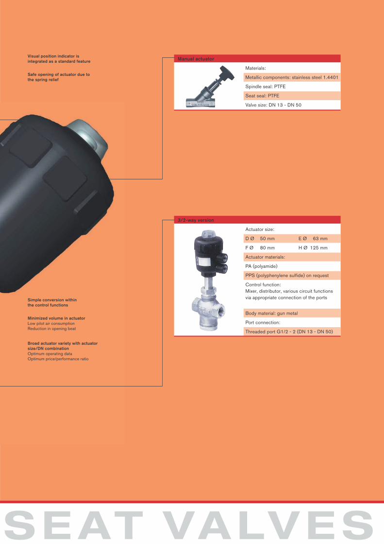
Materials:
Metallic components: stainless steel 1.4401
Spindle seal: PTFE
Seat seal: PTFE
Valve size: DN 13 - DN 50
Manual actuator
Actuator size:
D Ø 50 mm E Ø 63 mm
F Ø 80 mm H Ø 125 mm
Actuator materials:
PA (polyamide)
PPS (polyphenylene sulfide) on request
Control function:Mixer, distributor, various circuit functions via appropriate connection of the ports
Body material: gun metal
Port connection:
Threaded port G1/2 - 2 (DN 13 - DN 50)
3/2-way version
Simple conversion within the control functions
Minimized volume in actuatorLow pilot air consumptionReduction in opening beat
Visual position indicator is integrated as a standard feature
Safe opening of actuator due tothe spring relief
Broad actuator variety with actuatorsize/DN combination Optimum operating dataOptimum price/performance ratio
40/41
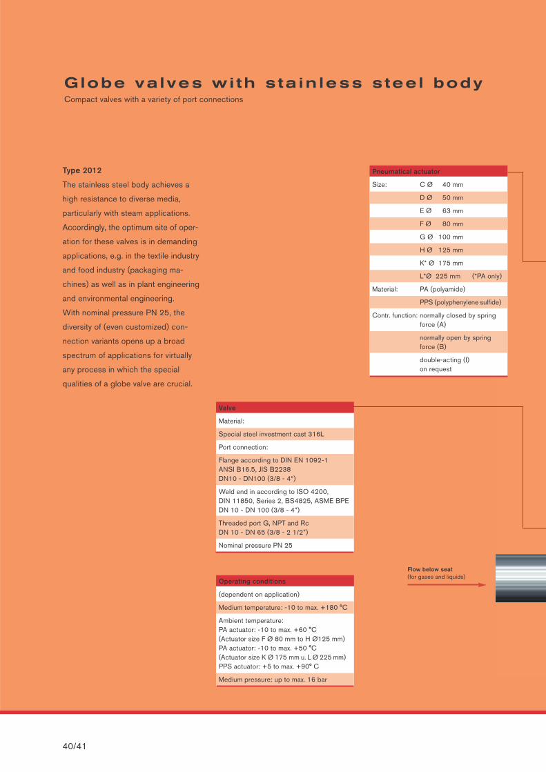
Globe va lves wi th s ta in less s tee l bodyCompact valves with a variety of port connections
Operating conditions
(dependent on application)
Medium temperature: -10 to max. +180 °C
Ambient temperature:PA actuator: -10 to max. +60 °C (Actuator size F Ø 80 mm to H Ø125 mm)PA actuator: -10 to max. +50 °C(Actuator size K Ø 175 mm u. L Ø 225 mm)PPS actuator: +5 to max. +90° C
Medium pressure: up to max. 16 bar
Valve
Material:
Special steel investment cast 316L
Port connection:
Flange according to DIN EN 1092-1ANSI B16.5, JIS B2238DN10 - DN100 (3/8 - 4“)
Weld end in according to ISO 4200,DIN 11850, Series 2, BS4825, ASME BPE DN 10 - DN 100 (3/8 - 4“)
Threaded port G, NPT and Rc DN 10 - DN 65 (3/8 - 2 1/2”)
Nominal pressure PN 25
Type 2012
The stainless steel body achieves a
high resistance to diverse media,
particularly with steam applications.
Accordingly, the optimum site of oper-
ation for these valves is in demanding
applications, e.g. in the textile industry
and food industry (packaging ma-
chines) as well as in plant engineering
and environmental engineering.
With nominal pressure PN 25, the
diversity of (even customized) con-
nection variants opens up a broad
spectrum of applications for virtually
any process in which the special
qualities of a globe valve are crucial.
Pneumatical actuator
Size: C Ø 40 mm
D Ø 50 mm
E Ø 63 mm
F Ø 80 mm
G Ø 100 mm
H Ø 125 mm
K* Ø 175 mm
L*Ø 225 mm (*PA only)
Material: PA (polyamide)
PPS (polyphenylene sulfide)
Contr. function: normally closed by springforce (A)
normally open by spring force (B)
double-acting (I) on request
Flow below seat (for gases and liquids)
SEAT VALVES
“Long Life“ self-readjusting packing gland made of PTFE
Integrated wiper in thespindle seal
Articulated disk replaces rigid seatfor high seat tightness
Proven graphite seal for use athigh temperature
PTFE seat sealElastomer on request
Simple conversion within the control functions
Minimized volume inactuatorLow pilot air consumptionReduction in openingbeat
Actuator can be turned through 360°
Visual position indicator is integrated as a standard feature
Safe opening of actuator due tospring relief
Broad actuator diversity with actuatorsize/DN valve combinationOptimum operating dataOptimum price/performance ratio
Flow above seat(for gases and steam only)
Interchangeable trim kit (articulated diskand valve seat) allows easy and safemaintenance
42/43
Angle-seat contro l va lves for s imple tasksAn cast effective solution with guaranteed Bürkert quality
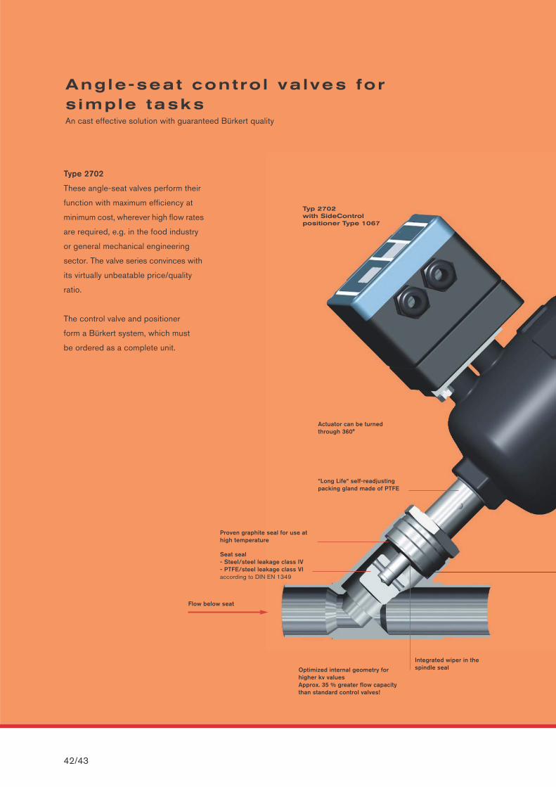
Optimized internal geometry for higher kv valuesApprox. 35 % greater flow capacitythan standard control valves!
Proven graphite seal for use at high temperature
“Long Life“ self-readjusting packing gland made of PTFE
Integrated wiper in thespindle seal
Seat seal- Steel/steel leakage class IV- PTFE/steel leakage class VIaccording to DIN EN 1349
Type 2702
These angle-seat valves perform their
function with maximum efficiency at
minimum cost, wherever high flow rates
are required, e.g. in the food industry
or general mechanical engineering
sector. The valve series convinces with
its virtually unbeatable price/quality
ratio.
The control valve and positioner
form a Bürkert system, which must
be ordered as a complete unit.
Actuator can be turned through 360°
Typ 2702 with SideControl positioner Type 1067
Flow below seat
SEAT VALVES
kv %
0
20
40
60
80
100
20 40 60 80 100POS %
Flow characteristic
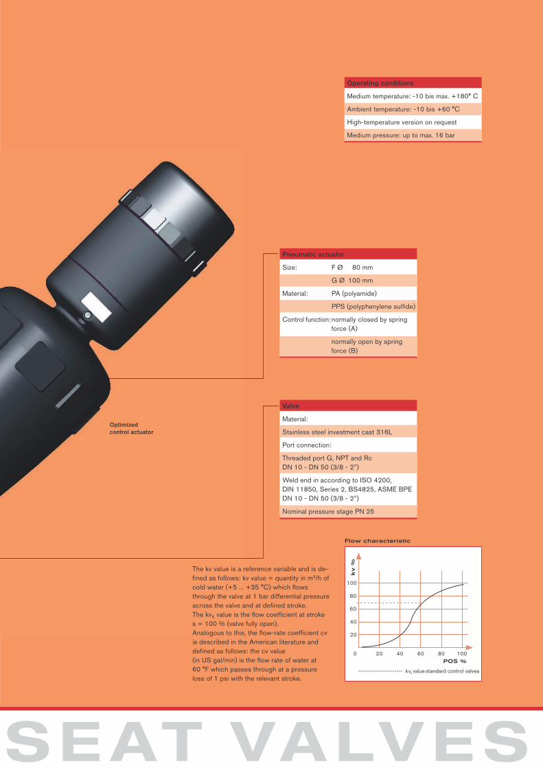
Operating conditions
Medium temperature: -10 bis max. +180° C
Ambient temperature: -10 bis +60 °C
High-temperature version on request
Medium pressure: up to max. 16 bar
Valve
Material:
Stainless steel investment cast 316L
Port connection:
Threaded port G, NPT and Rc DN 10 - DN 50 (3/8 - 2”)
Weld end in according to ISO 4200, DIN 11850, Series 2, BS4825, ASME BPE DN 10 - DN 50 (3/8 - 2”)
Nominal pressure stage PN 25
Pneumatic actuator
Size: F Ø 80 mm
G Ø 100 mm
Material: PA (polyamide)
PPS (polyphenylene sulfide)
Control function:normally closed by springforce (A)
normally open by spring force (B)
Optimized control actuator
The kv value is a reference variable and is de-fined as follows: kv value = quantity in m3/h ofcold water (+5 ... +35 °C) which flowsthrough the valve at 1 bar differential pressureacross the valve and at defined stroke.The kvS value is the flow coefficient at stroke s = 100 % (valve fully open).Analogous to this, the flow-rate coefficient cvis described in the American literature anddefined as follows: the cv value (in US gal/min) is the flow rate of water at 60 °F which passes through at a pressureloss of 1 psi with the relevant stroke.
---------------------- kvs value standard control valves
Globe contro l va lves for h igh-end tasks An ultra-compact series for a variety of applications
44/45
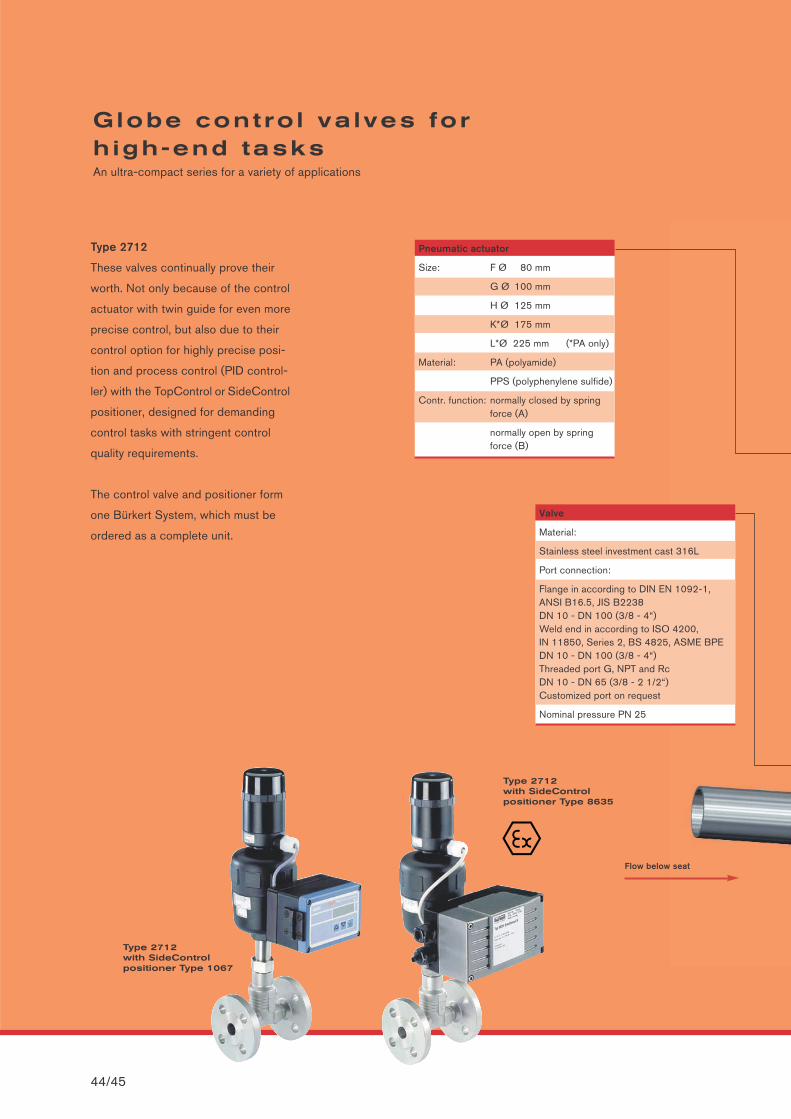
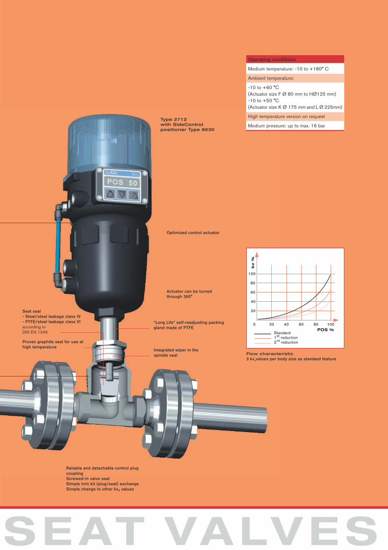
Type 2712
These valves continually prove their
worth. Not only because of the control
actuator with twin guide for even more
precise control, but also due to their
control option for highly precise posi-
tion and process control (PID control-
ler) with the TopControl or SideControl
positioner, designed for demanding
control tasks with stringent control
quality requirements.
The control valve and positioner form
one Bürkert System, which must be
ordered as a complete unit.
Pneumatic actuator
Size: F Ø 80 mm
G Ø 100 mm
H Ø 125 mm
K*Ø 175 mm
L*Ø 225 mm (*PA only)
Material: PA (polyamide)
PPS (polyphenylene sulfide)
Contr. function: normally closed by springforce (A)
normally open by spring force (B)
Valve
Material:
Stainless steel investment cast 316L
Port connection:
Flange in according to DIN EN 1092-1, ANSI B16.5, JIS B2238DN 10 - DN 100 (3/8 - 4“)Weld end in according to ISO 4200,IN 11850, Series 2, BS 4825, ASME BPEDN 10 - DN 100 (3/8 - 4“)Threaded port G, NPT and RcDN 10 - DN 65 (3/8 - 2 1/2“)Customized port on request
Nominal pressure PN 25
Type 2712with SideControl positioner Type 1067
Type 2712with SideControl positioner Type 8635
Flow below seat
SEAT VALVES
Reliable and detachable control plugcouplingScrewed-in valve seatSimple trim kit (plug/seat) exchangeSimple change to other kvS values
kv %
0
20
40
60
80
100
20 40 60 80 100POS %
Standard
Flow characteristic3 kvsvalues per body size as standard feature
Proven graphite seal for use athigh temperature
Integrated wiper in thespindle seal
“Long Life“ self-readjusting packing gland made of PTFE
Seat seal- Steel/steel leakage class IV- PTFE/steel leakage class VIaccording toDIN EN 1349
Operating conditions
Medium temperature: -10 to +180° C
Ambient temperature:
-10 to +60 °C (Actuator size F Ø 80 mm to HØ125 mm)-10 to +50 °C(Actuator size K Ø 175 mm and L Ø 225mm)
High temperature version on request
Medium pressure: up to max. 16 barType 2712with SideControl positioner Type 8630
Actuator can be turnedthrough 360°
Optimized control actuator
P46/47
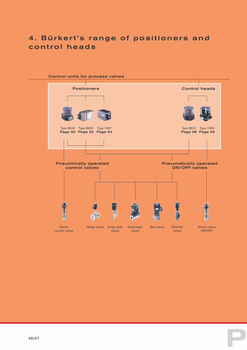
4. Bürker t ’s range of posi t ioners andcontro l heads
Pneumatically operated ON/OFF valves
Control heads
Type 8631Page 56
Type 1066Page 58
Pneumtically operatedcontrol valves
Control units for process valves
Positioners
Type 8630Page 50
Type 8635Page 52
Type 1067Page 54
Globe valvesSterilecontrol valves
Angle-seatvalves
Diaphragmvalves
Ball valves Butterfly valves
Sterile valvesON/OFF
O S I T I O N E R S
Bürkert not only specializes in valve
construction, but also in the know-
how required for its automation and
supplies a complete range of positioner
and control head equipment. We offer
complete systems of intermatched
process valves and integrated auto-
mation solutions. The modular design
of positioners and control heads allows
individualized solutions with an opti-
mum price/performance ratio.
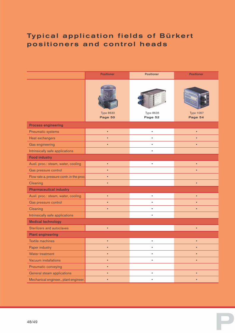
Typica l appl icat ion f ie lds of Bürker t posi t ioners and contro l heads
Positioner
Type 8630
Positioner
Type 8635
Positioner
Type 1067
Page 50 Page 52 Page 54
48/49 P
Process engineering
Pneumatic systems • • •
Heat exchangers • • •
Gas engineering • • •
Intrinsically safe applications •
Food industry
Auxil. proc.: steam, water, cooling • • •
Gas pressure control • •
Flow rate a. pressure contr. in the proc. •
Cleaning • •
Pharmaceutical industry
Auxil. proc.: steam, water, cooling • • •
Gas pressure control • • •
Cleaning • • •
Intrinsically safe applications •
Medical technology
Sterilizers and autoclaves • •
Plant engineering
Textile machines • • •
Paper industry • • •
Water treatment • • •
Vacuum installations • • •
Pneumatic conveying •
General steam applications • • •
Mechanical engineer., plant engineer. • • •
Control head
Type 8631
Control head
Type 1066
Page 56 Page 58
O S I T I O N E R S
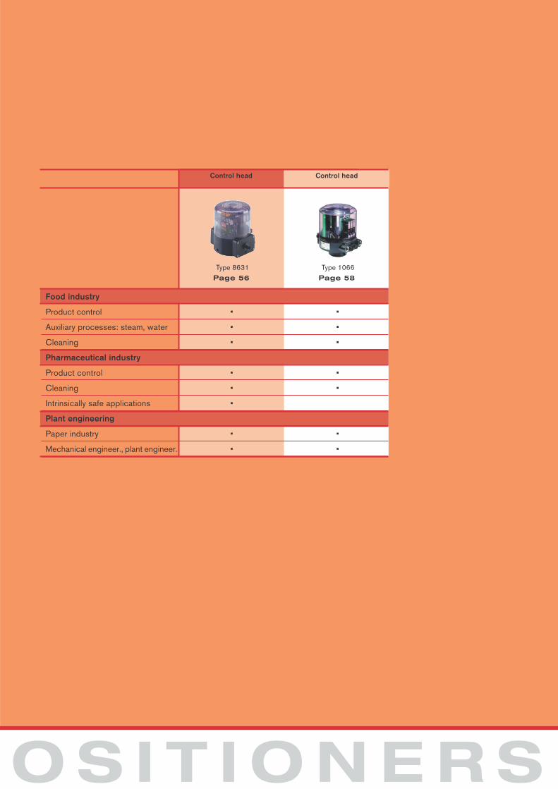
Food industry
Product control • •
Auxiliary processes: steam, water • •
Cleaning • •
Pharmaceutical industry
Product control • •
Cleaning • •
Intrinsically safe applications •
Plant engineering
Paper industry • •
Mechanical engineer., plant engineer. • •
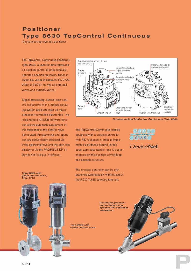
Actuating system with 2, 3, or 4solenoid valves
Supply pressure port
Controlports
Integrated analog di-splacement sensor
The TopControl Continuous can be
equipped with a process controller
with PID response in order to imple-
ment a distributed control. In this
case, a process control loop is super-
imposed on the position control loop
in a cascade structure.
The process controller can be pro-
grammed automatically with the aid of
the P.CO-TUNE software function.
Subassemblies TopControl Continuous, Type 8630
P
The TopControl Continuous positioner,
Type 8630, is used for electropneuma-
tic position control of pneumatically
operated positioning valves. These in-
clude e.g. valves in series 2712, 2700,
2730 and 2731 as well as both ball
valves and butterfly valves.
Signal processing, closed-loop con-
trol and control of the internal actuat-
ing system are performed via micro-
processor-controlled electronics. The
implemented X-TUNE software func-
tion allows automatic adjustment of
the positioner to the control valve
being used. Programming and opera-
tion are conveniently executed via
three operating keys and the plain text
display or via the PROFIBUS DP or
DeviceNet field bus interfaces.
Posi t ionerType 8630 TopContro l Cont inuousDigital electropneumatic positioner
50/51
Type 8630 with globe control valve,Type 2712
Distributed processcontrol loop using optional PID controllerintegration
Illustration without cap
Electricalconnectormodule
Screw for adjustinglower proximityswitch
Screw for adjustingupper proximityswitch
Operating modulewith display andkeysExhaust air port
Type 8630 with sterile control valve
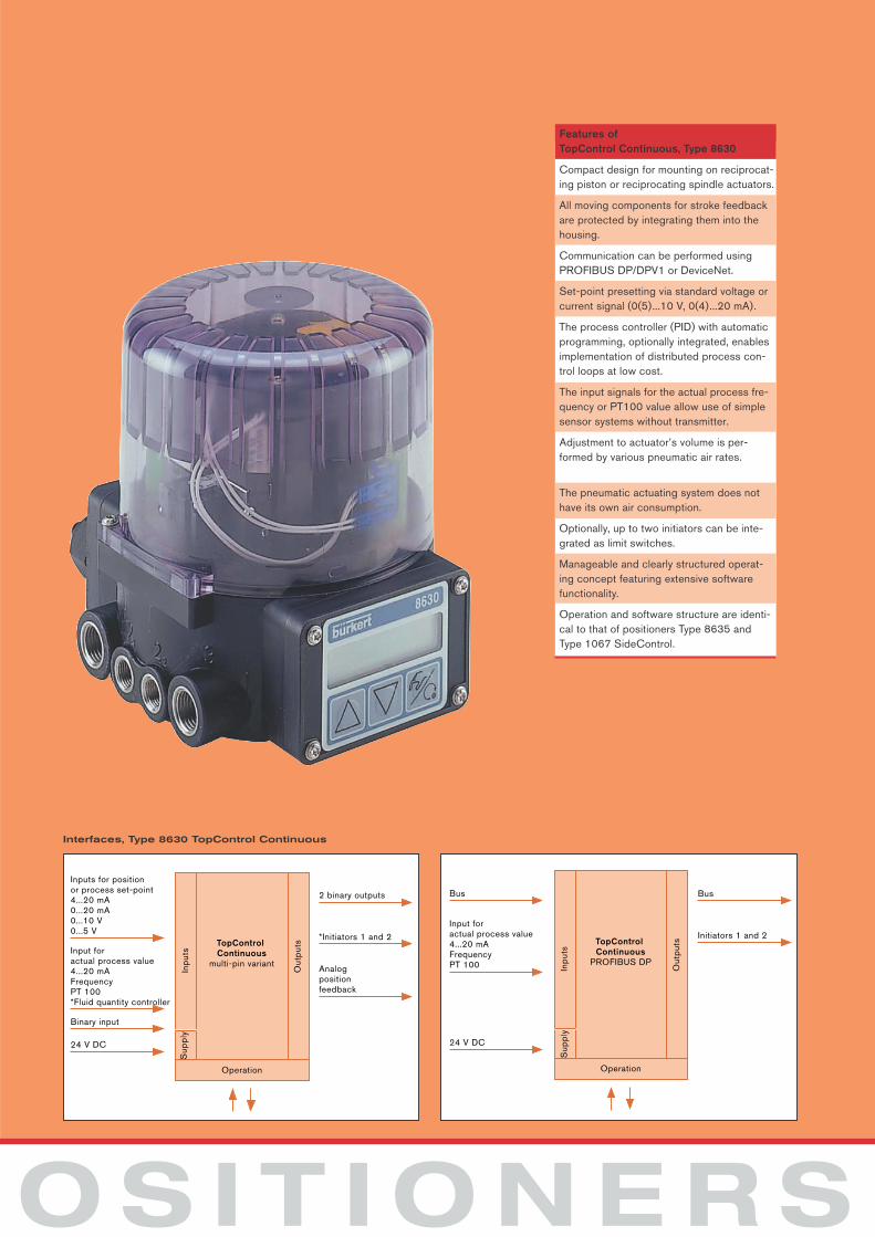
TopControl Continuous
multi-pin variant
Inp
uts
Sup
ply
Out
put
s
Inputs for positionor process set-point4...20 mA0...20 mA0...10 V0...5 V
Input for actual process value4...20 mAFrequencyPT 100*Fluid quantity controller
Binary input
24 V DC
Operation
2 binary outputs
*Initiators 1 and 2
Analog position feedback
TopControl Continuous
PROFIBUS DP
Inp
uts
Sup
ply
Out
put
s
Bus
Input foractual process value4...20 mAFrequencyPT 100
24 V DC
Operation
Bus
Initiators 1 and 2
Interfaces, Type 8630 TopControl Continuous
O S I T I O N E R S
Features of TopControl Continuous, Type 8630
Compact design for mounting on reciprocat-ing piston or reciprocating spindle actuators.
All moving components for stroke feedbackare protected by integrating them into thehousing.
Communication can be performed usingPROFIBUS DP/DPV1 or DeviceNet.
Set-point presetting via standard voltage orcurrent signal (0(5)...10 V, 0(4)...20 mA).
The process controller (PID) with automaticprogramming, optionally integrated, enablesimplementation of distributed process con-trol loops at low cost.
The input signals for the actual process fre-quency or PT100 value allow use of simplesensor systems without transmitter.
Adjustment to actuator’s volume is per-formed by various pneumatic air rates.
The pneumatic actuating system does nothave its own air consumption.
Optionally, up to two initiators can be inte-grated as limit switches.
Manageable and clearly structured operat-ing concept featuring extensive softwarefunctionality.
Operation and software structure are identi-cal to that of positioners Type 8635 andType 1067 SideControl.
P
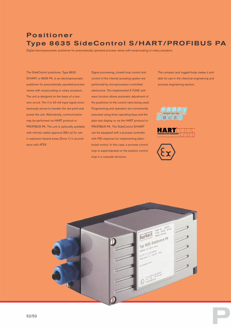
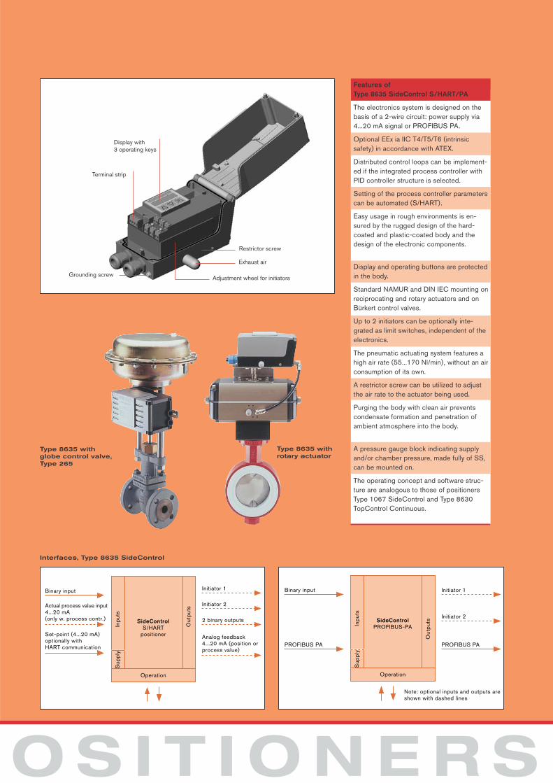
The SideControl positioner, Type 8635
S/HART or 8635 PA, is an electropneumatic
positioner for pneumatically operated process
valves with reciprocating or rotary actuators.
The unit is designed on the basis of a two-
wire circuit. The 4 to 20 mA input signal simul-
taneously serves to transfer the set-point and
power the unit. Alternatively, communication
may be performed via HART protocol or
PROFIBUS PA. The unit is optionally available
with intrinsic safety approval (EEx ia) for use
in explosion-hazard areas (Zone 1) in accord-
ance with ATEX.
Signal processing, closed-loop control and
control of the internal actuating system are
performed by microprocessor-controlled
electronics. The implemented X-TUNE soft-
ware function allows automatic adjustment of
the positioner to the control valve being used.
Programming and operation are conveniently
executed using three operating keys and the
plain text display or via the HART protocol or
PROFIBUS PA. The SideControl S/HART
can be equipped with a process controller
with PID response for implementing distri-
buted control. In this case, a process control
loop is superimposed on the position control
loop in a cascade structure.
The compact and rugged body makes it suit-
able for use in the chemical engineering and
process engineering sectors.
Posi t ionerType 8635 SideControl S/HART/PROFIBUS PADigital electropneumatic positioner for pneumatically operated process valves with reciprocating or rotary actuators
52/53
SideControlS/HART
positioner
Inp
uts
Sup
ply
Out
put
s
Binary input
Actual process value input4...20 mA(only w. process contr.)
Set-point (4...20 mA)optionally with HART communication
Operation
Initiator 1
Initiator 2
2 binary outputs
Analog feedback4...20 mA (position or process value)
SideControlPROFIBUS-PAIn
put
sS
upp
ly
Out
put
s
Binary input
PROFIBUS PA
Operation
Initiator 1
Initiator 2
PROFIBUS PA
Note: optional inputs and outputs are shown with dashed lines
Interfaces, Type 8635 SideControl
O S I T I O N E R S
Features of Type 8635 SideControl S/HART/PA
The electronics system is designed on thebasis of a 2-wire circuit: power supply via4...20 mA signal or PROFIBUS PA.
Optional EEx ia IIC T4/T5/T6 (intrinsic safety) in accordance with ATEX.
Distributed control loops can be implement-ed if the integrated process controller withPID controller structure is selected.
Setting of the process controller parameterscan be automated (S/HART).
Easy usage in rough environments is en-sured by the rugged design of the hard-coated and plastic-coated body and the design of the electronic components.
Display and operating buttons are protectedin the body.
Standard NAMUR and DIN IEC mounting onreciprocating and rotary actuators and onBürkert control valves.
Up to 2 initiators can be optionally inte-grated as limit switches, independent of theelectronics.
The pneumatic actuating system features ahigh air rate (55...170 Nl/min), without an airconsumption of its own.
A restrictor screw can be utilized to adjustthe air rate to the actuator being used.
Purging the body with clean air preventscondensate formation and penetration ofambient atmosphere into the body.
A pressure gauge block indicating supplyand/or chamber pressure, made fully of SS,can be mounted on.
The operating concept and software struc-ture are analogous to those of positionersType 1067 SideControl and Type 8630TopControl Continuous.
Type 8635 with globe control valve,Type 265
Display with 3 operating keys
Terminal strip
Restrictor screw
Exhaust air
Adjustment wheel for initiatorsGrounding screw
Type 8635 with rotary actuator
P
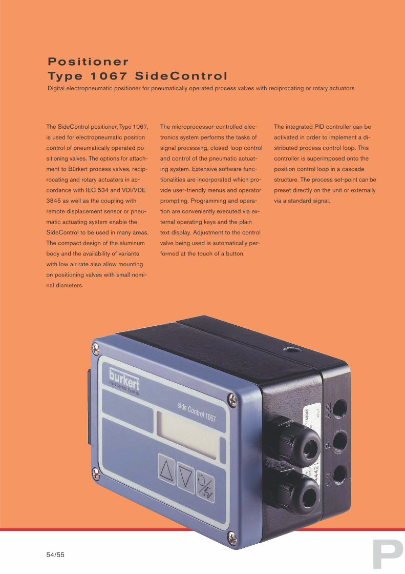
The SideControl positioner, Type 1067,
is used for electropneumatic position
control of pneumatically operated po-
sitioning valves. The options for attach-
ment to Bürkert process valves, recip-
rocating and rotary actuators in ac-
cordance with IEC 534 and VDI/VDE
3845 as well as the coupling with
remote displacement sensor or pneu-
matic actuating system enable the
SideControl to be used in many areas.
The compact design of the aluminum
body and the availability of variants
with low air rate also allow mounting
on positioning valves with small nomi-
nal diameters.
The microprocessor-controlled elec-
tronics system performs the tasks of
signal processing, closed-loop control
and control of the pneumatic actuat-
ing system. Extensive software func-
tionalities are incorporated which pro-
vide user-friendly menus and operator
prompting. Programming and opera-
tion are conveniently executed via ex-
ternal operating keys and the plain
text display. Adjustment to the control
valve being used is automatically per-
formed at the touch of a button.
The integrated PID controller can be
activated in order to implement a di-
stributed process control loop. This
controller is superimposed onto the
position control loop in a cascade
structure. The process set-point can be
preset directly on the unit or externally
via a standard signal.
Posi t ionerType 1067 S ideContro lDigital electropneumatic positioner for pneumatically operated process valves with reciprocating or rotary actuators
54/55
O S I T I O N E R S
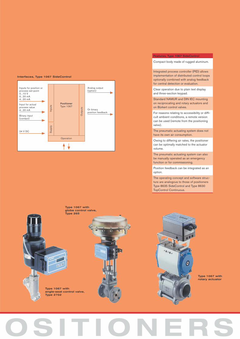
Features, Type 1067 SideControl
Compact body made of rugged aluminum.
Integrated process controller (PID) allowsimplementation of distributed control loopsoptionally combined with analog feedbackfor central detection or evaluation.
Clear operation due to plain text displayand three-section keypad.
Standard NAMUR and DIN IEC mountingon reciprocating and rotary actuators andon Bürkert control valves.
For reasons relating to accessibility or diffi-cult ambient conditions, a remote versioncan be used (remote from the positioningvalve).
The pneumatic actuating system does nothave its own air consumption.
Owing to differing air rates, the positionercan be optimally matched to the actuatorvolume.
The pneumatic actuating system can alsobe manually operated as an emergencyfunction or for commissioning.
Position feedback can be integrated as anoption.
The operating concept and software struc-ture are analogous to those of positionersType 8635 SideControl and Type 8630TopControl Continuous.
PositionerType 1067
Inp
uts
Sup
ply
Out
put
s
Inputs for position orprocess set-point0...10 V0...20 mA4...20 mA
Input for actualprocess value4...20 mA
Binary input(contact)
24 V DC
Operation
Analog output(option)
Or binary position feedback
Interfaces, Type 1067 SideControl
Type 1067 withangle-seat control valve,Type 2702
Type 1067 with rotary actuator
Type 1067 with globe control valve, Type 265
P
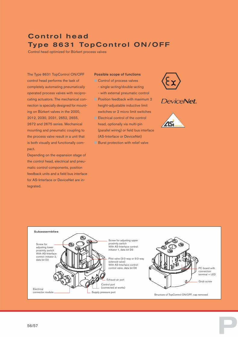
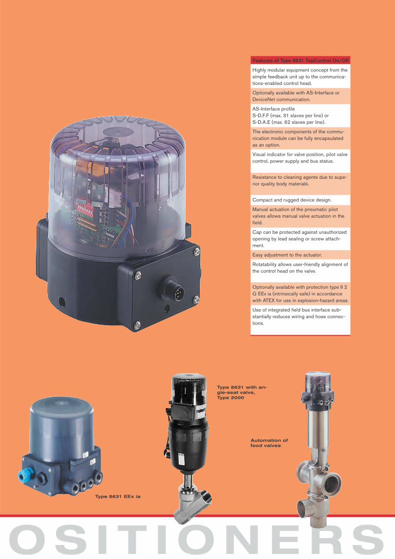
The Type 8631 TopControl ON/OFF
control head performs the task of
completely automating pneumatically
operated process valves with recipro-
cating actuators. The mechanical con-
nection is specially designed for mount-
ing on Bürkert valves in the 2000,
2012, 2030, 2031, 2652, 2655,
2672 and 2675 series. Mechanical
mounting and pneumatic coupling to
the process valve result in a unit that
is both visually and functionally com-
pact.
Depending on the expansion stage of
the control head, electrical and pneu-
matic control components, position
feedback units and a field bus interface
for AS-Interface or DeviceNet are in-
tegrated.
Possible scope of functions
■ Control of process valves
- single-acting/double-acting
- with external pneumatic control
■ Position feedback with maximum 2
height-adjustable inductive limit
switches or 2 micro limit switches
■ Electrical control of the control
head, optionally via multi-pin
(parallel wiring) or field bus interface
(AS-Interface or DeviceNet)
■ Burst protection with relief valve
Contro l headType 8631 TopContro l ON/OFFControl head optimized for Bürkert process valves
56/57
Electrical connector module Supply pressure port
Structure of TopControl ON/OFF, cap removed
Screw for adjusting lower proximity switchWith AS-Interfacecontrol: initiator 2,data bit D2
Control port (connected at works)
Exhaust air port
Pilot valve (3/2-way or 5/2-way solenoid valve)With AS-Interface control: control valve, data bit D0
Screw for adjusting upper proximity switchWith AS-Interface control: initiator 1, data bit D3
PC board withconnection terminal + LED
Grub screw
Subassemblies
O S I T I O N E R S
Features of Type 8631 TopControl On/Off
Highly modular equipment concept from thesimple feedback unit up to the communica-tions-enabled control head.
Optionally available with AS-Interface or DeviceNet communication.
AS-Interface profileS-D.F.F (max. 31 slaves per line) orS-D.A.E (max. 62 slaves per line).
The electronic components of the commu-nication module can be fully encapsulatedas an option.
Visual indicator for valve position, pilot valvecontrol, power supply and bus status.
Resistance to cleaning agents due to supe-rior quality body materials.
Compact and rugged device design.
Manual actuation of the pneumatic pilot valves allows manual valve actuation in thefield.
Cap can be protected against unauthorizedopening by lead sealing or screw attach-ment.
Easy adjustment to the actuator.
Rotatability allows user-friendly alignment ofthe control head on the valve.
Optionally available with protection type II 2G EEx ia (intrinsically safe) in accordancewith ATEX for use in explosion-hazard areas.
Use of integrated field bus interface sub-stantially reduces wiring and hose connec-tions.
Type 8631 EEx ia
Type 8631 with an-gle-seat valve, Type 2000
Automation offood valves
P
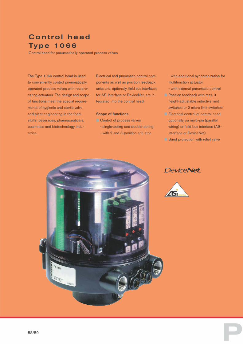
The Type 1066 control head is used
to conveniently control pneumatically
operated process valves with recipro-
cating actuators. The design and scope
of functions meet the special require-
ments of hygienic and sterile valve
and plant engineering in the food-
stuffs, beverages, pharmaceuticals,
cosmetics and biotechnology indu-
stries.
Electrical and pneumatic control com-
ponents as well as position feedback
units and, optionally, field bus interfaces
for AS-Interface or DeviceNet, are in-
tegrated into the control head.
Scope of functions
■ Control of process valves
- single-acting and double-acting
- with 2 and 3-position actuator
- with additional synchronization for
multifunction actuator
- with external pneumatic control
■ Position feedback with max. 3
height-adjustable inductive limit
switches or 2 micro limit switches
■ Electrical control of control head,
optionally via multi-pin (parallel
wiring) or field bus interface (AS-
Interface or DeviceNet)
■ Burst protection with relief valve
Contro l head Type 1066Control head for pneumatically operated process valves
58/59
O S I T I O N E R S
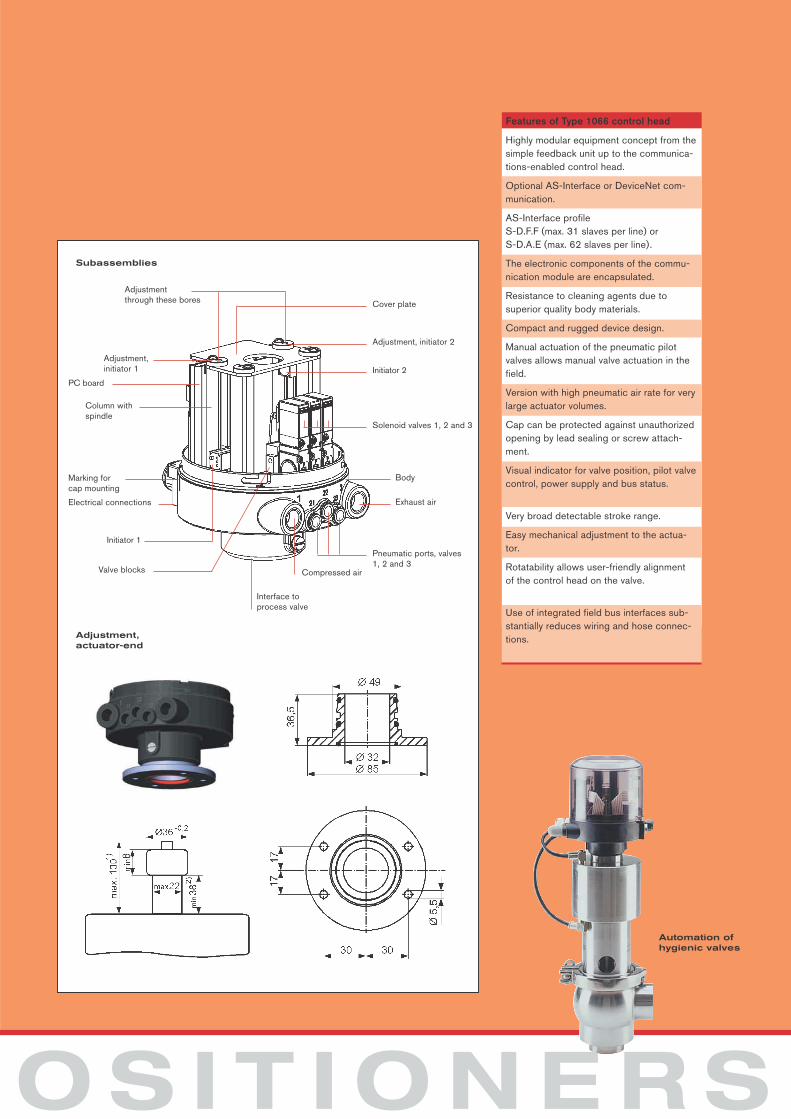
Features of Type 1066 control head
Highly modular equipment concept from thesimple feedback unit up to the communica-tions-enabled control head.
Optional AS-Interface or DeviceNet com-munication.
AS-Interface profile S-D.F.F (max. 31 slaves per line) orS-D.A.E (max. 62 slaves per line).
The electronic components of the commu-nication module are encapsulated.
Resistance to cleaning agents due tosuperior quality body materials.
Compact and rugged device design.
Manual actuation of the pneumatic pilot valves allows manual valve actuation in thefield.
Version with high pneumatic air rate for verylarge actuator volumes.
Cap can be protected against unauthorizedopening by lead sealing or screw attach-ment.
Visual indicator for valve position, pilot valvecontrol, power supply and bus status.
Very broad detectable stroke range.
Easy mechanical adjustment to the actua-tor.
Rotatability allows user-friendly alignmentof the control head on the valve.
Use of integrated field bus interfaces sub-stantially reduces wiring and hose connec-tions.
Automation of hygienic valves
Adjustment through these bores
Adjustment, initiator 1
Interface to process valve
Compressed air
Subassemblies
Adjustment, actuator-end
PC board
Column with spindle
Marking for cap mounting
Electrical connections
Initiator 1
Valve blocks
Pneumatic ports, valves 1, 2 and 3
Solenoid valves 1, 2 and 3
Initiator 2
Adjustment, initiator 2
Cover plate
Exhaust air
Body
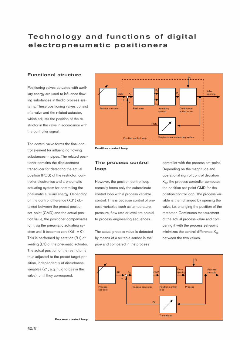
Functional structure
Positioning valves actuated with auxil-
iary energy are used to influence flow-
ing substances in fluidic process sys-
tems. These positioning valves consist
of a valve and the related actuator,
which adjusts the position of the re-
strictor in the valve in accordance with
the controller signal.
The control valve forms the final con-
trol element for influencing flowing
substances in pipes. The related posi-
tioner contains the displacement
transducer for detecting the actual
position (POS) of the restrictor, con-
troller electronics and a pneumatic
actuating system for controlling the
pneumatic auxiliary energy. Depending
on the control difference (Xd1) ob-
tained between the preset position
set-point (CMD) and the actual posi-
tion value, the positioner compensates
for it via the pneumatic actuating sy-
stem until it becomes zero (Xd1 = 0).
This is performed by aeration (B1) or
venting (E1) of the pneumatic actuator.
The actual position of the restrictor is
thus adjusted to the preset target po-
sition, independently of disturbance
variables (Z1, e.g. fluid forces in the
valve), until they correspond.
The process control
loop
However, the position control loop
normally forms only the subordinate
control loop within process variable
control. This is because control of pro-
cess variables such as temperature,
pressure, flow rate or level are crucial
to process-engineering sequences.
The actual process value is detected
by means of a suitable sensor in the
pipe and compared in the process
Technology and funct ions of d ig i ta l e lect ropneumat ic posi t ioners
60/61
controller with the process set-point.
Depending on the magnitude and
operational sign of control deviation
Xd2, the process controller computes
the position set-point CMD for the
position control loop. The process var-
iable is then changed by opening the
valve, i.e. changing the position of the
restrictor. Continuous measurement
of the actual process value and com-
paring it with the process set-point
minimizes the control difference Xd2
between the two values.
Position set-point Positioner Actuatingsystem
Displacement measuring system
Continuous-action valve
Valve openingCMD xd1 Px
B1
E1
+–
z1
Position control loop
POS
Processset-point
Process controller Position control loop
Transmitter
Process
Process variableSP xd2
Valve openingCMD
+–
z2
PV
Process control loop
Position control loop
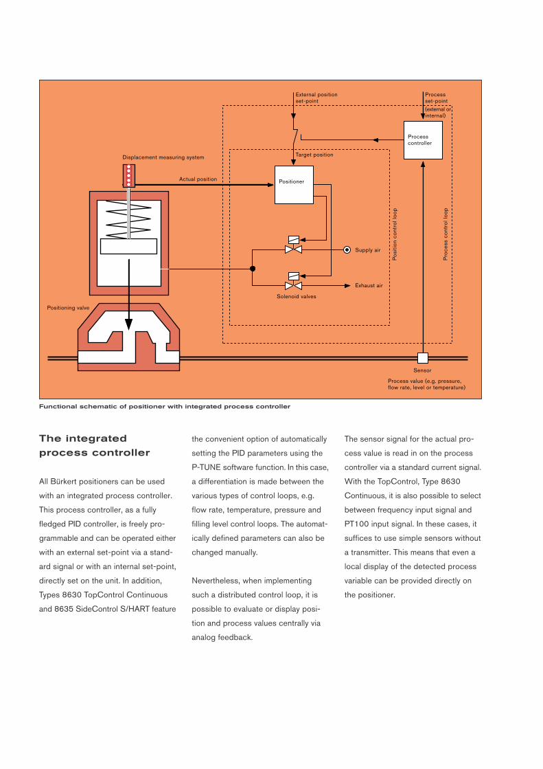
The integrated
process controller
All Bürkert positioners can be used
with an integrated process controller.
This process controller, as a fully
fledged PID controller, is freely pro-
grammable and can be operated either
with an external set-point via a stand-
ard signal or with an internal set-point,
directly set on the unit. In addition,
Types 8630 TopControl Continuous
and 8635 SideControl S/HART feature
the convenient option of automatically
setting the PID parameters using the
P-TUNE software function. In this case,
a differentiation is made between the
various types of control loops, e.g.
flow rate, temperature, pressure and
filling level control loops. The automat-
ically defined parameters can also be
changed manually.
Nevertheless, when implementing
such a distributed control loop, it is
possible to evaluate or display posi-
tion and process values centrally via
analog feedback.
The sensor signal for the actual pro-
cess value is read in on the process
controller via a standard current signal.
With the TopControl, Type 8630
Continuous, it is also possible to select
between frequency input signal and
PT100 input signal. In these cases, it
suffices to use simple sensors without
a transmitter. This means that even a
local display of the detected process
variable can be provided directly on
the positioner.
Process set-point
(external or internal)
Sensor
External position set-point
Target position
Process controller
Pro
cess
con
trol
loop
Pos
ition
con
trol
loop
Positioner
Supply air
Exhaust air
Solenoid valves
Process value (e.g. pressure, flow rate, level or temperature)
Actual position
Displacement measuring system
Positioning valve
Functional schematic of positioner with integrated process controller
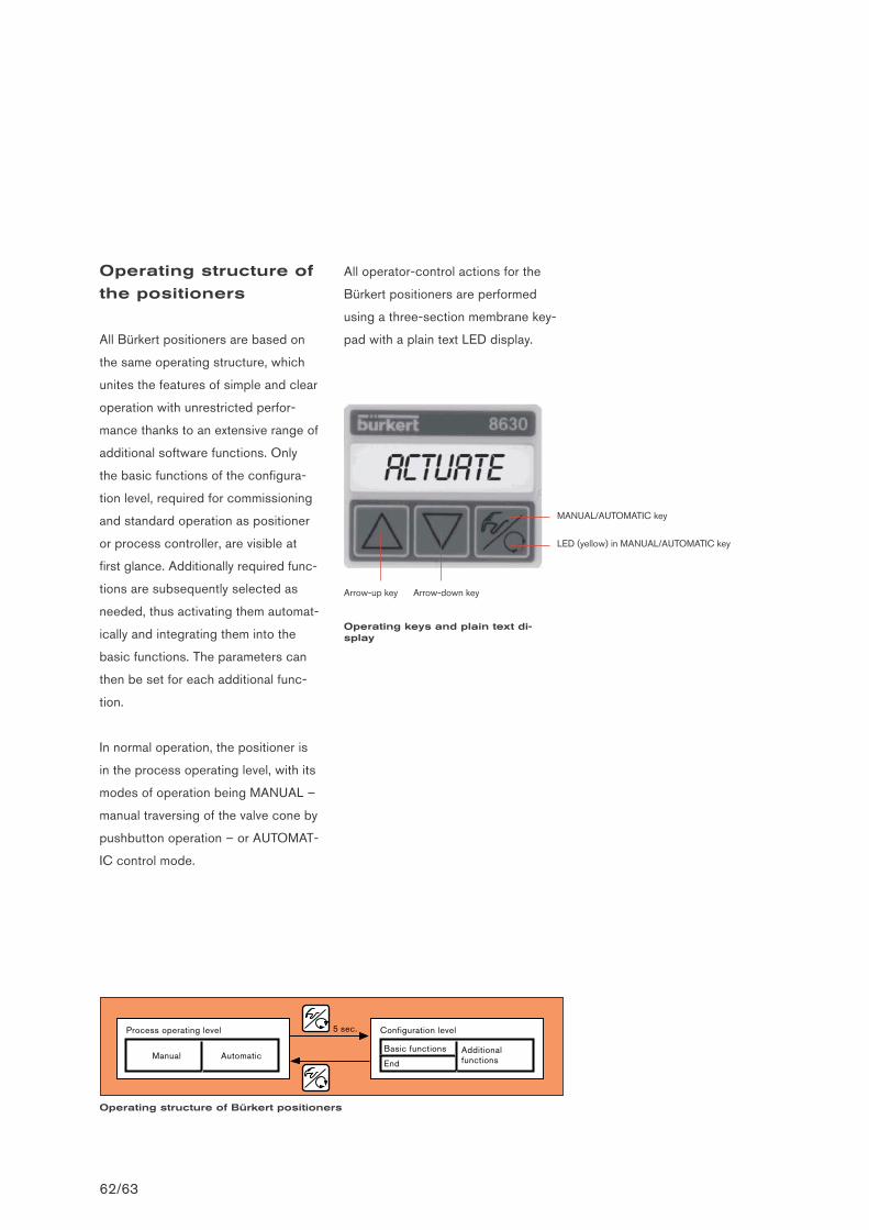
Operating structure of
the positioners
All Bürkert positioners are based on
the same operating structure, which
unites the features of simple and clear
operation with unrestricted perfor-
mance thanks to an extensive range of
additional software functions. Only
the basic functions of the configura-
tion level, required for commissioning
and standard operation as positioner
or process controller, are visible at
first glance. Additionally required func-
tions are subsequently selected as
needed, thus activating them automat-
ically and integrating them into the
basic functions. The parameters can
then be set for each additional func-
tion.
In normal operation, the positioner is
in the process operating level, with its
modes of operation being MANUAL –
manual traversing of the valve cone by
pushbutton operation – or AUTOMAT-
IC control mode.
All operator-control actions for the
Bürkert positioners are performed
using a three-section membrane key-
pad with a plain text LED display.
Headl ine zu den Reglern .
62/63
Process operating level Configuration level5 sec.
Manual AutomaticBasic functions
End
Additional functions
Operating structure of Bürkert positioners
MANUAL/AUTOMATIC key
LED (yellow) in MANUAL/AUTOMATIC key
Arrow-up key Arrow-down key
Operating keys and plain text di-splay
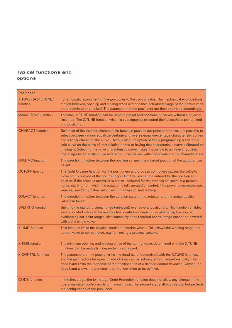
Typical functions and
options
Positioner
X.TUNE- (AUTOTUNE) For automatic adjustment of the positioner to the control valve. The mechanical end positions, function friction behavior, opening and closing times and possible actuator leakage of the control valve
are determined or checked. The parameters of the positioner are then optimized accordingly.
Manual TUNE function The manual TUNE function can be used to preset end positions on valves without a physical limit stop. The X.TUNE function which is subsequently executed then uses these pre-defined end positions.
CHARACT function Selection of the transfer characteristic between position set-point and stroke. It is possible toselect between various equal-percentage and inverse equal-percentage characteristic curvesand a linear characteristic curve. There is also the option of freely programming a character- istic curve on the basis of interpolation nodes or having that characteristic curve calibrated onthis basis. Selecting the valve characteristic curve makes it possible to achieve a requiredoperating characteristic curve and better utilize valves with inadequate control characteristics.
DIR.CMD function The direction of action between the position set-point and target position of the actuator canbe set.
CUTOFF function The Tight Closure function for the positioners and process controllers causes the valve to close tightly outside of the control range. Limit values can be entered for the position set-point or, if the process controller is active, indicated for the process set-point in a percent figure, starting from which the actuator is fully aerated or vented. This prevents increased seatwear caused by high flow velocities in the case of seat leakage.
DIR.ACT function The direction of action between the aeration state of the actuator and the actual position value can be set.
SPLTRNG function Splitting the standard signal range (set-point) over several positioners. This function enablesseveral control valves to be used as final control elements on an alternating basis or, withoverlapping set-point ranges, simultaneously if the required control range cannot be coveredwith just a single valve.
X.LIMIT function This function limits the physical stroke to settable values. This allows the working range of acontrol valve to be restricted, e.g. for limiting a process variable.
X.TIME function The minimum opening and closing times of the control valve, determined with the X.TUNEfunction, can be mutually independently increased.
X.CONTRL function The parameters of the positioner for the dead band, determined with the X.TUNE function,and the gain factors for opening and closing can be subsequently changed manually. Thedead band limits the response of the positioner as of a defined control deviation. Varying thedead band allows the permanent control deviation to be defined.
CODE function In the first stage, the two-stage Code Protection function does not allow any change in theoperating state, control mode or manual mode. The second stage allows change, but protectsthe configuration of the positioner.
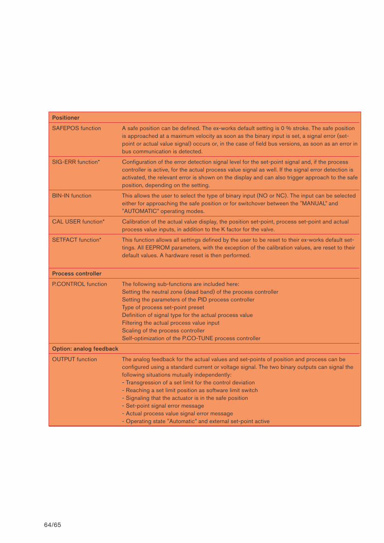
64/65
Positioner
SAFEPOS function A safe position can be defined. The ex-works default setting is 0 % stroke. The safe positionis approached at a maximum velocity as soon as the binary input is set, a signal error (set-point or actual value signal) occurs or, in the case of field bus versions, as soon as an error inbus communication is detected.
SIG-ERR function* Configuration of the error detection signal level for the set-point signal and, if the processcontroller is active, for the actual process value signal as well. If the signal error detection isactivated, the relevant error is shown on the display and can also trigger approach to the safeposition, depending on the setting.
BIN-IN function This allows the user to select the type of binary input (NO or NC). The input can be selectedeither for approaching the safe position or for switchover between the "MANUAL” and "AUTOMATIC” operating modes.
CAL USER function* Calibration of the actual value display, the position set-point, process set-point and actualprocess value inputs, in addition to the K factor for the valve.
SETFACT function* This function allows all settings defined by the user to be reset to their ex-works default set-tings. All EEPROM parameters, with the exception of the calibration values, are reset to theirdefault values. A hardware reset is then performed.
Process controller
P.CONTROL function The following sub-functions are included here:Setting the neutral zone (dead band) of the process controllerSetting the parameters of the PID process controllerType of process set-point presetDefinition of signal type for the actual process valueFiltering the actual process value inputScaling of the process controllerSelf-optimization of the P.CO-TUNE process controller
Option: analog feedback
OUTPUT function The analog feedback for the actual values and set-points of position and process can be configured using a standard current or voltage signal. The two binary outputs can signal the following situations mutually independently: - Transgression of a set limit for the control deviation- Reaching a set limit position as software limit switch- Signaling that the actuator is in the safe position - Set-point signal error message- Actual process value signal error message- Operating state "Automatic” and external set-point active
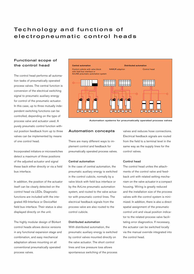
Functional scope of
the control head
The control head performs all automa-
tion tasks of pneumatically operated
process valves. The central function is
conversion of the electrical switching
signal to pneumatic auxiliary energy
for control of the pneumatic actuator.
In this case, up to three mutually inde-
pendent switching functions can be
controlled, depending on the type of
process valve and actuator used. A
purely pneumatic control function with-
out position feedback from up to three
valves can be implemented by means
of one control head.
Incorporated initiators or microswitches
detect a maximum of three positions
of the adjusted actuator and signal
these back either directly or via a field
bus interface.
In addition, the position of the actuator
itself can be clearly detected on the
control head via LEDs. Diagnostic
functions are included with the inte-
grated AS-Interface or DeviceNet
field bus interface. Their status is also
displayed directly on the unit.
The highly modular design of Bürkert
control heads allows device versions
in any functional expansion stage and
combination, and easy mechanical
adaptation allows mounting on all
conventional pneumatically operated
process valves.
Control cubicle with valve block with field bus interface orAirLINE pneumatic automation system
NAMUR adaption Control head
Central automation Distributed automation
Automation concepts
There are many different ways to im-
plement control and feedback for
pneumatically operated process valves.
Central automation
In the case of central automation, the
pneumatic auxiliary energy is switched
in the control cubicle, normally by a
valve block with field bus interface or
by the AirLine pneumatic automation
system, and routed to the valve actua-
tor with pneumatic control lines. The
electrical feedback signals from the
process valve are also routed to the
control cubicle.
Distributed automation
With distributed automation, the
pneumatic auxiliary energy is switched
by control valves mounted directly on
the valve actuator. The short control
lines and low pressure loss allows
spontaneous switching of the process
valves and reduces hose connections.
Electrical feedback signals are routed
from the field to a terminal level in the
same way as the supply lines for the
control valves.
Control head
The control head unites the attach-
ments of the control valve and feed-
back unit with related setting mecha-
nism on the valve actuator in a compact
housing. Wiring is greatly reduced
and the installation size of the process
valves with the control system is mini-
mized. In addition, there is also a direct
spatial assignment of the pneumatic
control unit and visual position indica-
tor to the related process valve facili-
tating error diagnostics. If necessary,
the actuator can be switched locally
via the manual override integrated into
the control head.
Automation systems for pneumatically operated process valves
Technology and funct ions of e lect ropneumat ic contro l heads
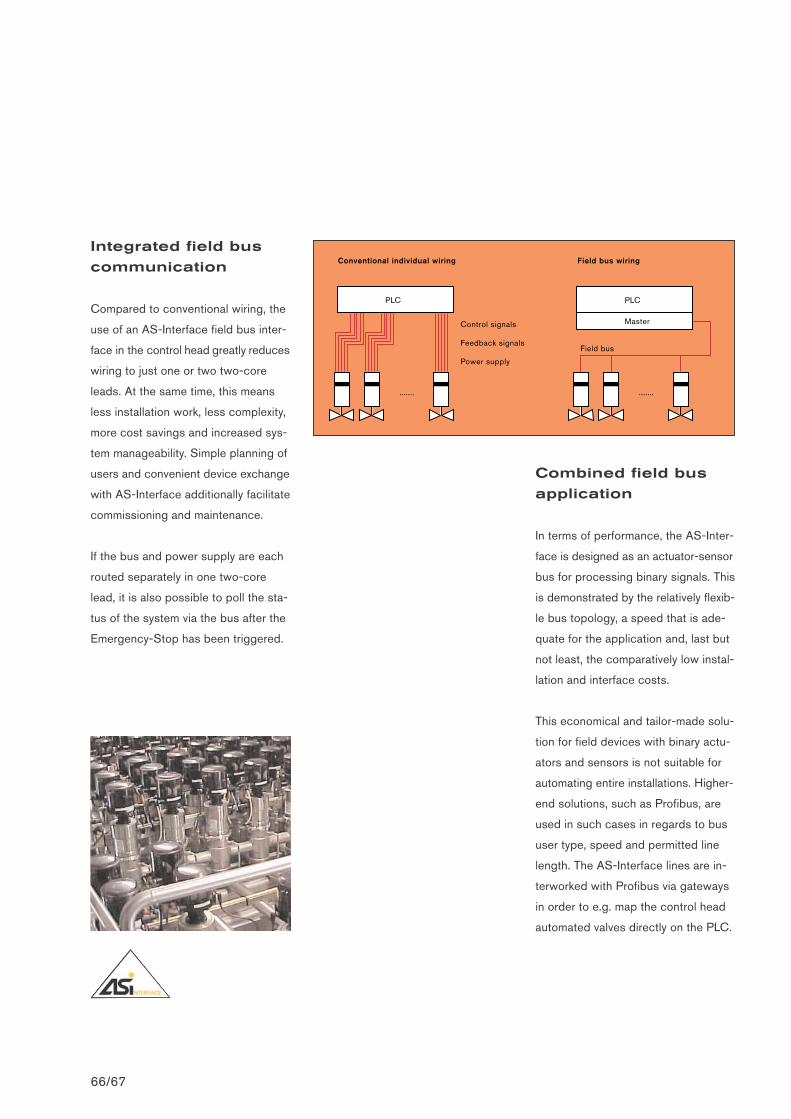
Combined field bus
application
In terms of performance, the AS-Inter-
face is designed as an actuator-sensor
bus for processing binary signals. This
is demonstrated by the relatively flexib-
le bus topology, a speed that is ade-
quate for the application and, last but
not least, the comparatively low instal-
lation and interface costs.
This economical and tailor-made solu-
tion for field devices with binary actu-
ators and sensors is not suitable for
automating entire installations. Higher-
end solutions, such as Profibus, are
used in such cases in regards to bus
user type, speed and permitted line
length. The AS-Interface lines are in-
terworked with Profibus via gateways
in order to e.g. map the control head
automated valves directly on the PLC.
Integrated field bus
communication
Compared to conventional wiring, the
use of an AS-Interface field bus inter-
face in the control head greatly reduces
wiring to just one or two two-core
leads. At the same time, this means
less installation work, less complexity,
more cost savings and increased sys-
tem manageability. Simple planning of
users and convenient device exchange
with AS-Interface additionally facilitate
commissioning and maintenance.
If the bus and power supply are each
routed separately in one two-core
lead, it is also possible to poll the sta-
tus of the system via the bus after the
Emergency-Stop has been triggered.
Headl ine zu den Reglern .
66/67
Conventional individual wiring
PLC
.......
Field bus wiring
PLC
Master
.......
Field bus
Control signals
Feedback signals
Power supply
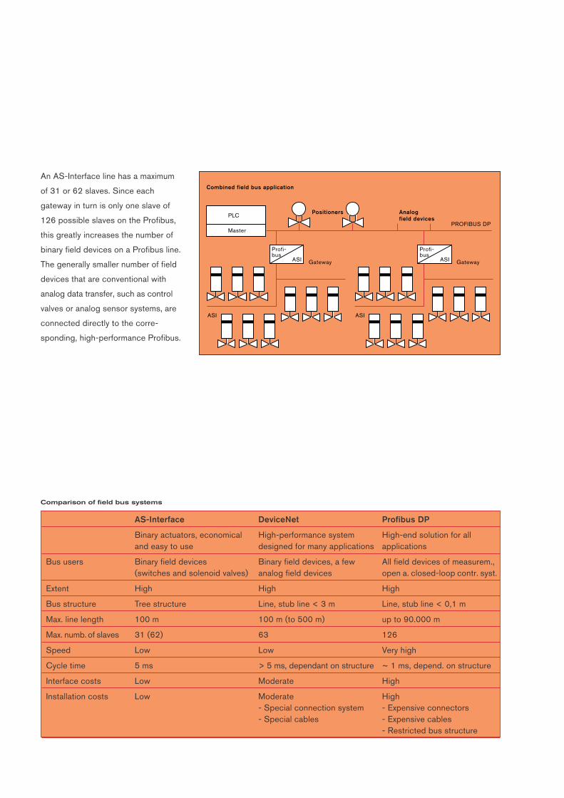
AS-Interface DeviceNet Profibus DP
Binary actuators, economical High-performance system High-end solution for all and easy to use designed for many applications applications
Bus users Binary field devices Binary field devices, a few All field devices of measurem.,(switches and solenoid valves) analog field devices open a. closed-loop contr. syst.
Extent High High High
Bus structure Tree structure Line, stub line < 3 m Line, stub line < 0,1 m
Max. line length 100 m 100 m (to 500 m) up to 90.000 m
Max. numb. of slaves 31 (62) 63 126
Speed Low Low Very high
Cycle time 5 ms > 5 ms, dependant on structure ~ 1 ms, depend. on structure
Interface costs Low Moderate High
Installation costs Low Moderate High- Special connection system - Expensive connectors- Special cables - Expensive cables
- Restricted bus structure
PROFIBUS DP
Positioners Analogfield devices
Combined field bus application
PLC
Master
Profi-bus
ASI Gateway
ASI
Profi-bus
ASI Gateway
ASI
An AS-Interface line has a maximum
of 31 or 62 slaves. Since each
gateway in turn is only one slave of
126 possible slaves on the Profibus,
this greatly increases the number of
binary field devices on a Profibus line.
The generally smaller number of field
devices that are conventional with
analog data transfer, such as control
valves or analog sensor systems, are
connected directly to the corre-
sponding, high-performance Profibus.
Comparison of field bus systems
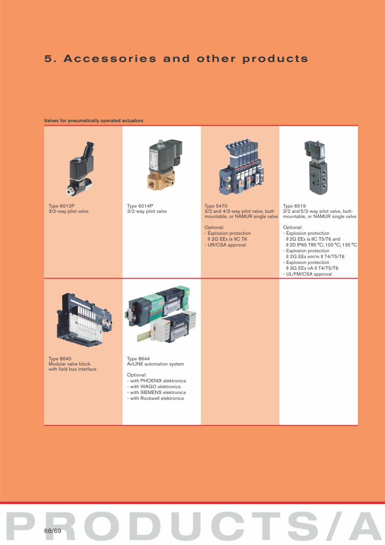
PRODUCTS/A68/69
5. Accessor ies and other products
Valves for pneumatically operated actuators
Type 6012P3/2-way pilot valve
Type 6014P3/2-way pilot valve
Type 54703/2 and 4/2-way pilot valve, butt-mountable, or NAMUR single valve
Optional:- Explosion protection
II 2G EEx ia IIC T6- UR/CSA approval
Type 65193/2 and 5/2-way pilot valve, butt-mountable, or NAMUR single valve
Optional:- Explosion protection
II 2G EEx ia IIC T5/T6 andII 2D IP65 T85 °C; 100 °C; 135 °C
- Explosion protection II 2G EEx em/m II T4/T5/T6
- Explosion protection II 3G EEx nA II T4/T5/T6
- UL/FM/CSA approval
Type 8640Modular valve blockwith field bus interface
Type 8644AirLINE automation system
Optional:- with PHOENIX elektronics- with WAGO elektronics- with SIEMENS elektronics- with Rockwell elektronics
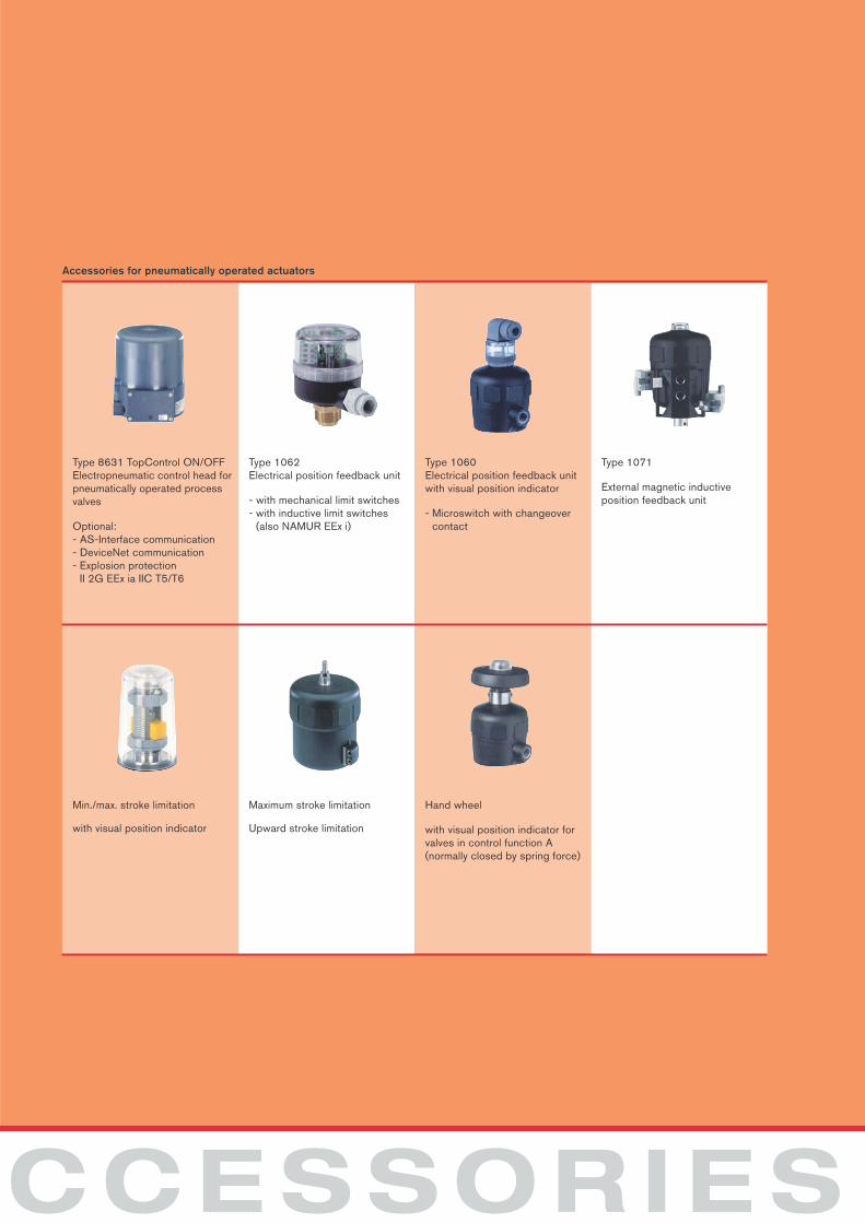
CCESSORIES
Accessories for pneumatically operated actuators
Type 8631 TopControl ON/OFFElectropneumatic control head forpneumatically operated processvalves
Optional:- AS-Interface communication- DeviceNet communication- Explosion protection
II 2G EEx ia IIC T5/T6
Type 1062Electrical position feedback unit
- with mechanical limit switches- with inductive limit switches
(also NAMUR EEx i)
Type 1060Electrical position feedback unitwith visual position indicator
- Microswitch with changeovercontact
Type 1071
External magnetic inductive position feedback unit
Min./max. stroke limitation
with visual position indicator
Maximum stroke limitation
Upward stroke limitation
Hand wheel
with visual position indicator forvalves in control function A (normally closed by spring force)
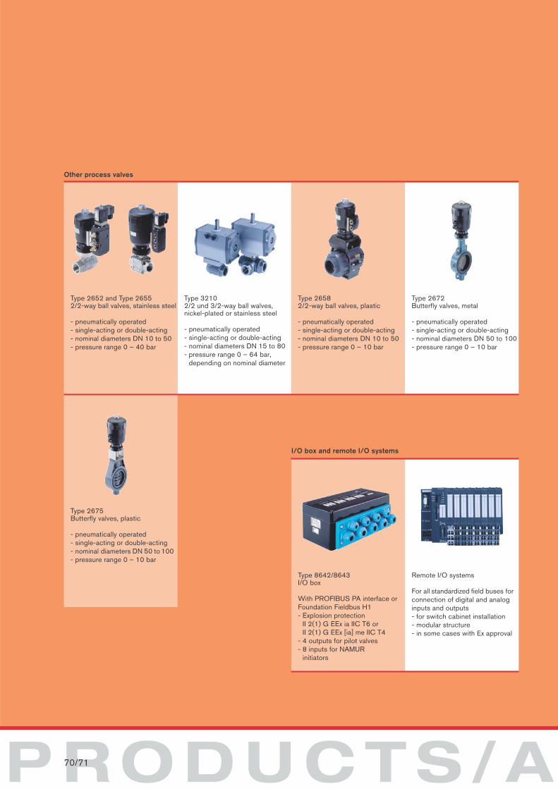
PRODUCTS/A70/71
I/O box and remote I/O systems
Type 8642/8643I/O box
With PROFIBUS PA interface orFoundation Fieldbus H1- Explosion protection
II 2(1) G EEx ia IIC T6 orII 2(1) G EEx [ia] me IIC T4
- 4 outputs for pilot valves - 8 inputs for NAMUR
initiators
Remote I/O systems
For all standardized field buses forconnection of digital and analoginputs and outputs- for switch cabinet installation- modular structure- in some cases with Ex approval
Other process valves
Type 2652 and Type 26552/2-way ball valves, stainless steel
- pneumatically operated- single-acting or double-acting- nominal diameters DN 10 to 50- pressure range 0 – 40 bar
Type 32102/2 und 3/2-way ball walves, nickel-plated or stainless steel
- pneumatically operated- single-acting or double-acting- nominal diameters DN 15 to 80- pressure range 0 – 64 bar,
depending on nominal diameter
Type 26582/2-way ball valves, plastic
- pneumatically operated- single-acting or double-acting- nominal diameters DN 10 to 50- pressure range 0 – 10 bar
Type 2672Butterfly valves, metal
- pneumatically operated- single-acting or double-acting- nominal diameters DN 50 to 100- pressure range 0 – 10 bar
Type 2675Butterfly valves, plastic
- pneumatically operated- single-acting or double-acting- nominal diameters DN 50 to 100- pressure range 0 – 10 bar
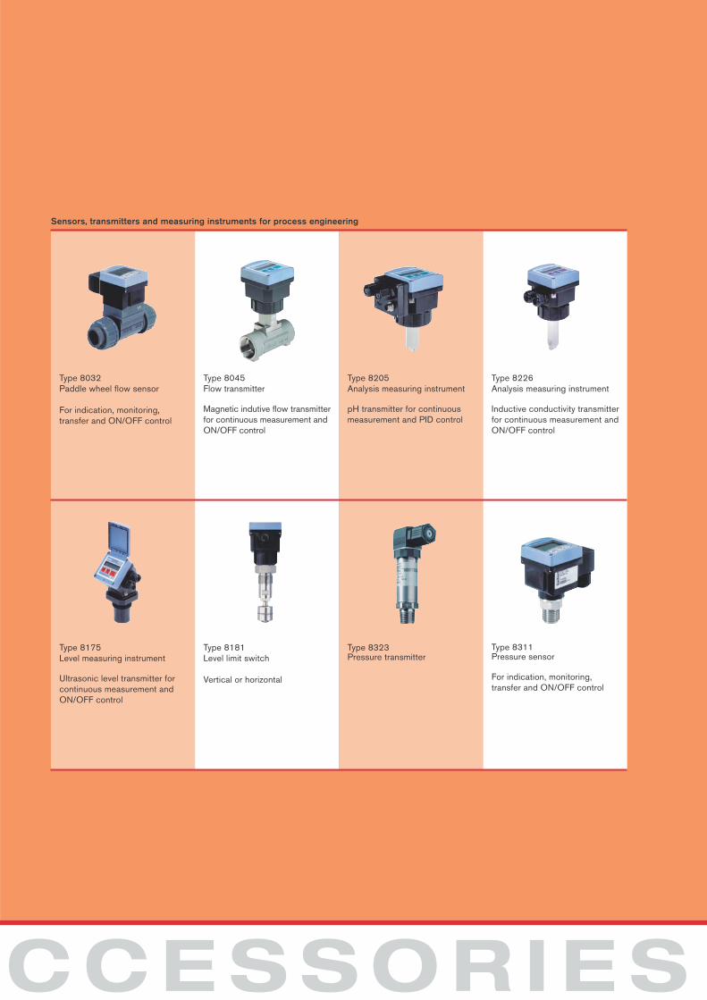
CCESSORIES
Sensors, transmitters and measuring instruments for process engineering
Type 8032Paddle wheel flow sensor
For indication, monitoring, transfer and ON/OFF control
Type 8045Flow transmitter
Magnetic indutive flow transmitterfor continuous measurement andON/OFF control
Type 8205Analysis measuring instrument
pH transmitter for continuousmeasurement and PID control
Type 8226Analysis measuring instrument
Inductive conductivity transmitterfor continuous measurement andON/OFF control
Type 8175Level measuring instrument
Ultrasonic level transmitter forcontinuous measurement andON/OFF control
Type 8181Level limit switch
Vertical or horizontal
Type 8323Pressure transmitter
Type 8311Pressure sensor
For indication, monitoring, transfer and ON/OFF control
Burkert Service and Distribution Network
AustraliaBurkert Fluid Control SystemsNo. 2 Welder Road,Seven Hills, NSW 2147Tel. +61 1300 888 868Fax +61 1300 888 076
AustriaBurkert-Contromatic Ges.m.b.H.Diefenbachgasse 1-3 1150 Wien (Vienna)Tel. +43 (0) 1 894 13 33Fax +43 (0) 1 894 13 00
BelgiumBurkert-Contromatic SABijkhoevelaan 32110 WijnegemTel. +32 (0) 3 325 89 00Fax +32 (0) 3 325 61 61
BrazilBurkert-Contromatic Brasil Ltda.Rua Américo Brasiliense no. 2171 cj 100704715-005 São Paulo - SPTel. +55 (0) 11 5182 0011Fax +55 (0) 11 5182 8899
CanadaBurkert Contromatic Inc.760 Pacific Road, Unit 3Oakville (Ontario) L6L 6M5Tel. +1 905 847-55 66Fax +1 905 847-90 06
ChinaBurkert Contromatic (Shanghai) Co., Ltd.Room J1, 3rd floorTai Gu RoadWai Gao Qiao Free Trade ZoneShanghai 200131Tel. +86 21 5868 21 19Fax +86 21 5868 21 20
Czech RepublicBurkert-Contromatic Ges.m.b.H.Branch-Office AustriaKrenova 35602 00 BrnoTel. +42 05 43 25 25 05Fax +42 05 43 25 25 06
DenmarkBurkert-Contromatic A/SHørkær 242730 HerlevTel. +45 44 50 75 00Fax +45 44 50 75 75
FinlandBurkert OyAtomitie 500370 HelsinkiTel. +358 (0) 9 549 70 600Fax +358 (0) 9 503 12 75
FranceBurkert Contromatic FranceRue du GiessenBP 2167220 Triembach au ValTel. +33 (0) 3 88 58 91 11Fax +33 (0) 3 88 57 20 08
GermanyBürkert GmbH & Co. KGChristian-Bürkert-Straße 13-17D-74653 IngelfingenTel. +49 (0) 7940 10 111Fax +49 (0) 7940 10 448
Hong KongBurkert-Contromatic (China/HK) Ltd.Unit 708, Prosperity Centre77-81, Container Port RoadKwai Chung N.T., Hong KongTel. +85 2 2480 1202Fax +85 2 2418 1945
ItalyBurkert Contromatic Italiana S.p.A.Centro Direzionale „Colombirolo“Via Roma 7420060 Cassina De´Pecchi (Mi)Tel. +39 02 95 90 71Fax +39 02 95 90 72 51
JapanBurkert-Contromatic Ltd.1-8-5 Asagaya MinamiSuginami-kuTokyo 166-0004Tel. +81 (0) 3 5305 3610Fax +81 (0) 3 5305 3611
KoreaBurkert Contromatic Korea Co., Ltd.287-2, Doksan 4 DongKumcheon-kuSeoul 153-811Tel. +82 (0) 3 3462 5592Fax +82 (0) 3 3462 5594
NetherlandsBurkert-Contromatic BVComputerweg 93542 DP UtrechtTel. +31 (0) 346 58 10 10Fax +31 (0) 346 56 37 17
New ZealandBurkert Contromatic Ltd.2A, Unit L, Edinburgh StPenrose, AucklandTel. +64 (0) 9 622 2840Fax +64 (0) 9 622 2847
NorwayBurkert Contromatic A/SHvamstubben 172013 SkjettenTel. +47 63 84 44 10Fax +47 63 84 44 55
PhilippinesBurkert Contromatic Philippines, Inc.8467 West Service RoadSouth Superhighway, SunvalleyParanaque City, Metro ManillaTel. +63 2 776 43 84Fax +63 2 776 43 82
PolandBurkert-Contromatic Ges.m.b.H.Branch-Office AustriaBernardynska street 14 a02-904 WarszawaTel. +48 22 840 60 10Fax +48 22 840 60 11
PortugalBurkert ContromaticTel. +351 21 212 84 90Fax +351 21 212 84 91
SingaporeBurkert Contromatic Singapore Pte. Ltd.51 Ubi Avenue 1, #03-14Paya Ubi Industrial ParkTel. +65 6844 2233Fax +65 6844 3532
South AfricaBurkert Contromatic (Pty) Ltd.P.O. Box 26260East Rand1462Tel. +27 11 574 60 00Fax + 27 11 574 60 26
SpainBurkert Contromatic S.A.Avda. Barcelona, 4008970 Sant Joan Despi (Barcelona)Tel. +34 93 477 79 80Fax +34 93 477 79 81
SwedenBurkert-Contromatic ABSkeppsbron 13 B211 20 MalmöTel. +46 (0) 40 664 51 00Fax +46 (0) 40 664 51 01
SwitzerlandBurkert-Contromatic AG SchweizBösch 716331 HünenbergTel. +41 (0) 41 785 66 66Fax +41 (0) 41 785 66 33
TaiwanBurkert Contromatic Taiwan Ltd.9F, No. 32, Chenggong Road, Sec,1,Nangang DistrictTaipeiTaiwan 115, R.O.C.Tel. +886 2 2653 78 68Fax +886 2 2653 79 68
TurkeyBurkert Contromatic AkiskanKontrol Sistemleri Ticaret A.S.1203/8 Sok. No 2-EYenisehir, IzmirTel. +90 (0) 232 459 53 95Fax +90 (0) 232 459 76 94
United KingdomBurkert Fluid Control SystemsBrimscombe Port Business ParkBrimscombe, Stroud, Glos., GL5 2QFTel. +44 (0) 1453 73 13 53Fax +44 (0) 1453 73 13 43
USABurkert Contromatic USA2602 McGaw AvenueIrvine, CA 92614U.S.A.Tel. +1 949 223 3100Fax +1 949 223 3198
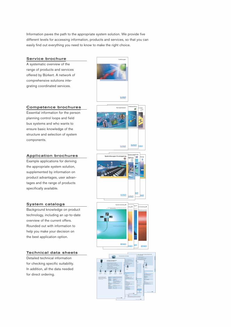
Service brochure
A systematic overview of the
range of products and services
offered by Bürkert. A network of
comprehensive solutions inte-
grating coordinated services.
Competence brochures
Essential information for the person
planning control loops and field
bus systems and who wants to
ensure basic knowledge of the
structure and selection of system
components.
Application brochures
Example applications for deriving
the appropriate system solution,
supplemented by information on
product advantages, user advan-
tages and the range of products
specifically available.
System catalogs
Background knowledge on product
technology, including an up-to-date
overview of the current offers.
Rounded out with information to
help you make your decision on
the best application option.
Technical data sheets
Detailed technical information
for checking specific suitability.
In addition, all the data needed
for direct ordering.
Information paves the path to the appropriate system solution. We provide five
different levels for accessing information, products and services, so that you can
easily find out everything you need to know to make the right choice.
The smart choice of Fluid Control Systems
Zulassungen
Systemkatalog 6
Magnetventile I Prozess- und Regelventile I Pneumatik
Sensoren I MicroFluidics I MFC und Proportionalventile
The smart choice of Fluid Control Systems
Systemkatalog 1
Magnetventile I Prozess- und Regelventile I Pneumatik
Sensoren I MicroFluidics I MFC und Proportionalventile
The smart choice of Fluid Control Systems
Systemkatalog 2
Magnetventile I Prozess- und Regelventile I Pneumatik
Sensoren I MicroFluidics I MFC und Proportionalventile
The smart choice of Fluid Control Systems
Systemkatalog 5
Magnetventile I Prozess- und Regelventile I Pneumatik
Sensoren I MicroFluidics I MFC und Proportionalventile
The smart choice of Fluid Control Systems


8940
50 /
11/
03 /
Bur
eau
Sch
irle
Bürkert Fluid Control Systems, Christian-Bürkert-Straße 13–17, 74653 Ingelfingen, Germany
Tel.+49 (0) 79 40/10-0,Fax+49 (0) 79 40/10-204, [email protected], www.buerkert.com