1072608A02 EP2 Pump System - Nordsonemanuals.nordson.com/finishing/files/Cont-Liq/1072608A02.pdf ·...
37
EP2 Pump System Customer Product Manual Part 1072608A02 Issued 5/08 NORDSON CORPORATION AMHERST, OHIO USA For parts and technical support, call the Industrial Coating Systems Customer Support Center at (800) 433-9319 or contact your local Nordson representative. This document is subject to change without notice. Check http://emanuals.nordson.com for the latest version.
Transcript of 1072608A02 EP2 Pump System - Nordsonemanuals.nordson.com/finishing/files/Cont-Liq/1072608A02.pdf ·...
EP2 Pump System
Customer Product ManualPart 1072608A02
Issued 5/08
NORDSON CORPORATION AMHERST, OHIO USA
For parts and technical support, call the Industrial CoatingSystems Customer Support Center at (800) 433-9319 or
contact your local Nordson representative.
This document is subject to change without notice.Check http://emanuals.nordson.com for the latest version.
Part 1072608A02 � 2008 Nordson Corporation
tents
Table of ContentsSafety 1. . . . . . . . . . . . . . . . . . . . . . . . . . . . . . . . . . . . . . .
Qualified Personnel 1. . . . . . . . . . . . . . . . . . . . . . . . .Intended Use 1. . . . . . . . . . . . . . . . . . . . . . . . . . . . . .Regulations and Approvals 1. . . . . . . . . . . . . . . . . .Personal Safety 2. . . . . . . . . . . . . . . . . . . . . . . . . . . .
High-Pressure Fluids 2. . . . . . . . . . . . . . . . . . . . .Fire Safety 3. . . . . . . . . . . . . . . . . . . . . . . . . . . . . . . .
Halogenated Hydrocarbon Solvent Hazards 4.Action in the Event of a Malfunction 4. . . . . . . . . . .Disposal 4. . . . . . . . . . . . . . . . . . . . . . . . . . . . . . . . . .
Safety Labels 5. . . . . . . . . . . . . . . . . . . . . . . . . . . . . . . .Description 7. . . . . . . . . . . . . . . . . . . . . . . . . . . . . . . . . .
Pump Operation 9. . . . . . . . . . . . . . . . . . . . . . . . . . .System Operation 10. . . . . . . . . . . . . . . . . . . . . . . . . .Specifications 12. . . . . . . . . . . . . . . . . . . . . . . . . . . . . .
Installation 13. . . . . . . . . . . . . . . . . . . . . . . . . . . . . . . . . .Oil Change Kit Installation 13. . . . . . . . . . . . . . . . . . .Mounting 13. . . . . . . . . . . . . . . . . . . . . . . . . . . . . . . . . .Pump Oil Level 14. . . . . . . . . . . . . . . . . . . . . . . . . . . .Electrical Connections 14. . . . . . . . . . . . . . . . . . . . . .
Wiring Guidelines 14. . . . . . . . . . . . . . . . . . . . . . . .US Version Wiring Diagram 15. . . . . . . . . . . . . . .CE Version Wiring Diagram 16. . . . . . . . . . . . . . .
Fluid System Installation 16. . . . . . . . . . . . . . . . . . . .Inlet and Outlet Connections 16. . . . . . . . . . . . . .Fluid System Installation Guidelines 17. . . . . . . .
Operation 18. . . . . . . . . . . . . . . . . . . . . . . . . . . . . . . . . . .System Startup 18. . . . . . . . . . . . . . . . . . . . . . . . . . . .Changing Coating Materials/Flushingthe System 20. . . . . . . . . . . . . . . . . . . . . . . . . . . . . . . .Shutdown 21. . . . . . . . . . . . . . . . . . . . . . . . . . . . . . . . . .
Short-Term Shutdown 21. . . . . . . . . . . . . . . . . . . . .Long-Term Shutdown 21. . . . . . . . . . . . . . . . . . . . .
Pressure Relief Valve Adjustment 22. . . . . . . . . . . .Maintenance 23. . . . . . . . . . . . . . . . . . . . . . . . . . . . . . . .
EP2 Pump Oil Change 23. . . . . . . . . . . . . . . . . . . . . .Daily Maintenance Procedures 24. . . . . . . . . . . . . . .Monthly Maintenance Procedures 25. . . . . . . . . . . .Annual Maintenance Procedures 25. . . . . . . . . . . . .
Troubleshooting 26. . . . . . . . . . . . . . . . . . . . . . . . . . . . .Repair 28. . . . . . . . . . . . . . . . . . . . . . . . . . . . . . . . . . . . . .Parts 29. . . . . . . . . . . . . . . . . . . . . . . . . . . . . . . . . . . . . . .
Using the Illustrated Parts List 29. . . . . . . . . . . . . . .EP2 Pump System 30. . . . . . . . . . . . . . . . . . . . . . . . .Accessory Group 34. . . . . . . . . . . . . . . . . . . . . . . . . . .
Options 34. . . . . . . . . . . . . . . . . . . . . . . . . . . . . . . . . . . . .Oil Change Kit 34. . . . . . . . . . . . . . . . . . . . . . . . . . . . . .PTFE High-Pressure Fluid Hose Assemblies 34. . .Inline (Supply) Filter 34. . . . . . . . . . . . . . . . . . . . . . . . .
Contact UsNordson Corporation welcomes requests for information, comments, andinquiries about its products. General information about Nordson can befound on the Internet using the following address:http://www.nordson.com.Address all correspondence to:
Nordson CorporationAttn: Customer Service555 Jackson StreetAmherst, OH 44001
NoticeThis is a Nordson Corporation publication which is protected by copyright.Original copyright date 2004. No part of this document may bephotocopied, reproduced, or translated to another language without theprior written consent of Nordson Corporation. The information containedin this publication is subject to change without notice.
Trademarks
Nordson and the Nordson logo are registered trademarks of NordsonCorporation.
EP2 Pump System 1
Part 1072608A02� 2008 Nordson Corporation
EP2 Pump System
Safety Read and follow these safety instructions. Task- and equipment-specificwarnings, cautions, and instructions are included in equipmentdocumentation where appropriate.
Make sure all equipment documentation, including these instructions, isaccessible to persons operating or servicing equipment.
Qualified Personnel Equipment owners are responsible for making sure that Nordson equipmentis installed, operated, and serviced by qualified personnel. Qualifiedpersonnel are those employees or contractors who are trained to safelyperform their assigned tasks. They are familiar with all relevant safety rulesand regulations and are physically capable of performing their assignedtasks.
Intended Use Use of Nordson equipment in ways other than those described in thedocumentation supplied with the equipment may result in injury to personsor damage to property.
Some examples of unintended use of equipment include
� using incompatible materials
� making unauthorized modifications
� removing or bypassing safety guards or interlocks
� using incompatible or damaged parts
� using unapproved auxiliary equipment
� operating equipment in excess of maximum ratings
Regulations and Approvals Make sure all equipment is rated and approved for the environment in whichit is used. Any approvals obtained for Nordson equipment will be voided ifinstructions for installation, operation, and service are not followed.
EP2 Pump System2
Part 1072608A02 � 2008 Nordson Corporation
Personal Safety To prevent injury follow these instructions.
� Do not operate or service equipment unless you are qualified.
� Do not operate equipment unless safety guards, doors, or covers areintact and automatic interlocks are operating properly. Do not bypass ordisarm any safety devices.
� Keep clear of moving equipment. Before adjusting or servicing movingequipment, shut off the power supply and wait until the equipmentcomes to a complete stop. Lock out power and secure the equipment toprevent unexpected movement.
� Relieve (bleed off) hydraulic and pneumatic pressure before adjusting orservicing pressurized systems or components. Disconnect, lock out,and tag switches before servicing electrical equipment.
� While operating manual spray guns, make sure you are grounded.Wear electrically conductive gloves or a grounding strap connected tothe gun handle or other true earth ground. Do not wear or carry metallicobjects such as jewelry or tools.
� If you receive even a slight electrical shock, shut down all electrical orelectrostatic equipment immediately. Do not restart the equipment untilthe problem has been identified and corrected.
� Obtain and read Material Safety Data Sheets (MSDS) for all materialsused. Follow the manufacturer’s instructions for safe handling and useof materials, and use recommended personal protection devices.
� Make sure the spray area is adequately ventilated.
� To prevent injury, be aware of less-obvious dangers in the workplacethat often cannot be completely eliminated, such as hot surfaces, sharpedges, energized electrical circuits, and moving parts that cannot beenclosed or otherwise guarded for practical reasons.
High-Pressure Fluids High-pressure fluids, unless they are safely contained, are extremelyhazardous. Always relieve fluid pressure before adjusting or servicing highpressure equipment. A jet of high-pressure fluid can cut like a knife andcause serious bodily injury, amputation, or death. Fluids penetrating theskin can also cause toxic poisoning.
If you suffer a fluid injection injury, seek medical care immediately. Ifpossible, provide a copy of the MSDS for the injected fluid to the health careprovider.
EP2 Pump System 3
Part 1072608A02� 2008 Nordson Corporation
The National Spray Equipment Manufacturers Association has created awallet card that you should carry when you are operating high-pressurespray equipment. These cards are supplied with your equipment. Thefollowing is the text of this card:
WARNING: Any injury caused by high pressure liquid can be serious. Ifyou are injured or even suspect an injury:
� Go to an emergency room immediately.
� Tell the doctor that you suspect an injection injury.
� Show him this card
� Tell him what kind of material you were spraying
MEDICAL ALERT—AIRLESS SPRAY WOUNDS: NOTE TO PHYSICIAN
Injection in the skin is a serious traumatic injury. It is important to treat theinjury surgically as soon as possible. Do not delay treatment to researchtoxicity. Toxicity is a concern with some exotic coatings injected directly intothe bloodstream.
Consultation with a plastic surgeon or a reconstructive hand surgeon maybe advisable.
The seriousness of the wound depends on where the injury is on the body,whether the substance hit something on its way in and deflected causingmore damage, and many other variables including skin microflora residingin the paint or gun which are blasted into the wound. If the injected paintcontains acrylic latex and titanium dioxide that damage the tissue’sresistance to infection, bacterial growth will flourish. The treatment thatdoctors recommend for an injection injury to the hand includes immediatedecompression of the closed vascular compartments of the hand to releasethe underlying tissue distended by the injected paint, judicious wounddebridement, and immediate antibiotic treatment.
Fire Safety To avoid a fire or explosion, follow these instructions.
� Ground all conductive equipment. Use only grounded air and fluidhoses. Check equipment and workpiece grounding devices regularly.Resistance to ground must not exceed one megohm.
� Shut down all equipment immediately if you notice static sparking orarcing. Do not restart the equipment until the cause has been identifiedand corrected.
� Do not smoke, weld, grind, or use open flames where flammablematerials are being used or stored.
� Do not heat materials to temperatures above those recommended bythe manufacturer. Make sure heat monitoring and limiting devices areworking properly.
EP2 Pump System4
Part 1072608A02 � 2008 Nordson Corporation
Fire Safety (contd)
� Provide adequate ventilation to prevent dangerous concentrations ofvolatile particles or vapors. Refer to local codes or your material MSDSfor guidance.
� Do not disconnect live electrical circuits when working with flammablematerials. Shut off power at a disconnect switch first to preventsparking.
� Know where emergency stop buttons, shutoff valves, and fireextinguishers are located. If a fire starts in a spray booth, immediatelyshut off the spray system and exhaust fans.
� Shut off electrostatic power and ground the charging system beforeadjusting, cleaning, or repairing electrostatic equipment.
� Clean, maintain, test, and repair equipment according to the instructionsin your equipment documentation.
� Use only replacement parts that are designed for use with originalequipment. Contact your Nordson representative for parts informationand advice.
Halogenated Hydrocarbon Solvent Hazards Do not use halogenated hydrocarbon solvents in a pressurized system thatcontains aluminum components. Under pressure, these solvents can reactwith aluminum and explode, causing injury, death, or property damage.Halogenated hydrocarbon solvents contain one or more of the followingelements:
Element Symbol Prefix
Fluorine F “Fluoro-”
Chlorine Cl “Chloro-”
Bromine Br “Bromo-”
Iodine I “Iodo-”
Check your material MSDS or contact your material supplier for moreinformation. If you must use halogenated hydrocarbon solvents, contactyour Nordson representative for information about compatible Nordsoncomponents.
Action in the Event of a Malfunction If a system or any equipment in a system malfunctions, shut off the systemimmediately and perform the following steps:
� Disconnect and lock out system electrical power. Close hydraulic andpneumatic shutoff valves and relieve pressures.
� Identify the reason for the malfunction and correct it before restarting thesystem.
Disposal Dispose of equipment and materials used in operation and servicingaccording to local codes.
EP2 Pump System 5
Part 1072608A02� 2008 Nordson Corporation
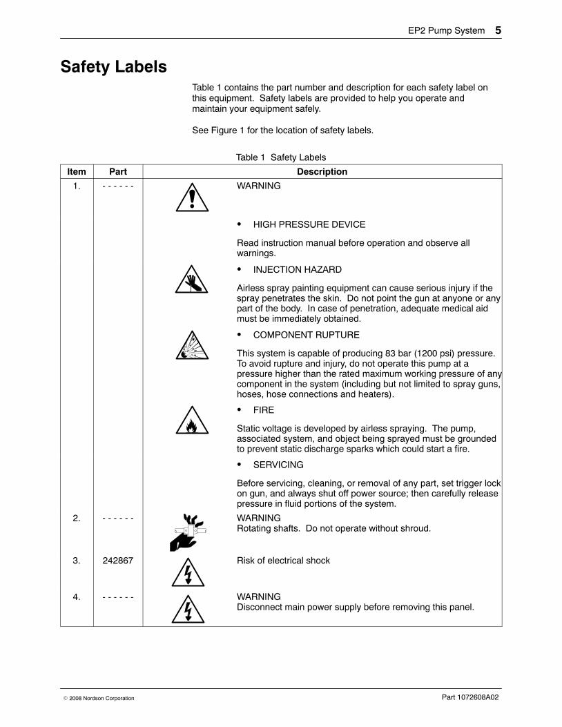
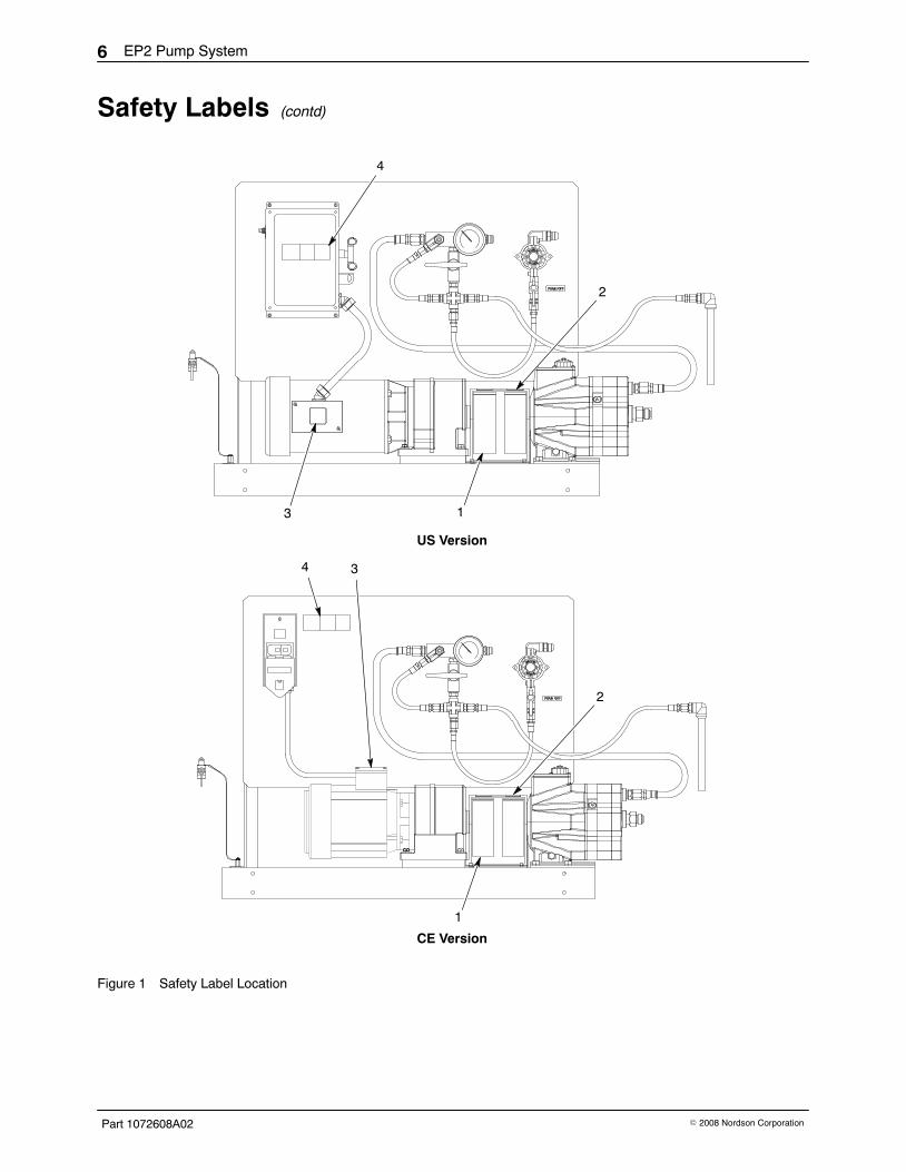
Safety Labels Table 1 contains the part number and description for each safety label onthis equipment. Safety labels are provided to help you operate andmaintain your equipment safely.
See Figure 1 for the location of safety labels.
Table 1 Safety Labels
Item Part Description
1. - - - - - - WARNING
� HIGH PRESSURE DEVICE
Read instruction manual before operation and observe allwarnings.
� INJECTION HAZARD
Airless spray painting equipment can cause serious injury if thespray penetrates the skin. Do not point the gun at anyone or anypart of the body. In case of penetration, adequate medical aidmust be immediately obtained.
� COMPONENT RUPTURE
This system is capable of producing 83 bar (1200 psi) pressure.To avoid rupture and injury, do not operate this pump at apressure higher than the rated maximum working pressure of anycomponent in the system (including but not limited to spray guns,hoses, hose connections and heaters).
� FIRE
Static voltage is developed by airless spraying. The pump,associated system, and object being sprayed must be groundedto prevent static discharge sparks which could start a fire.
� SERVICING
Before servicing, cleaning, or removal of any part, set trigger lockon gun, and always shut off power source; then carefully releasepressure in fluid portions of the system.
2. - - - - - - WARNINGRotating shafts. Do not operate without shroud.
3. 242867 Risk of electrical shock
4. - - - - - - WARNINGDisconnect main power supply before removing this panel.
EP2 Pump System6
Part 1072608A02 � 2008 Nordson Corporation
Safety Labels (contd)
3
4
1
2
34
1
2
US Version
CE Version
Figure 1 Safety Label Location
EP2 Pump System 7
Part 1072608A02� 2008 Nordson Corporation
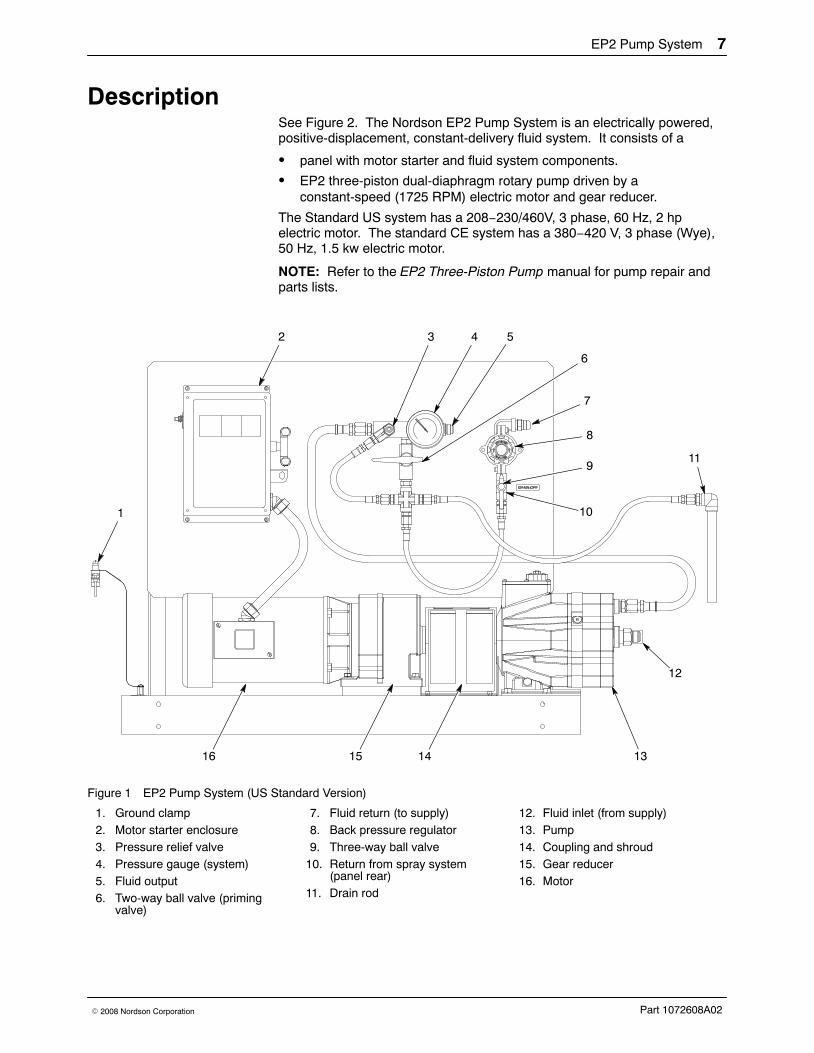
Description See Figure 2. The Nordson EP2 Pump System is an electrically powered,positive-displacement, constant-delivery fluid system. It consists of a
� panel with motor starter and fluid system components.
� EP2 three-piston dual-diaphragm rotary pump driven by aconstant-speed (1725 RPM) electric motor and gear reducer.
The Standard US system has a 208−230/460V, 3 phase, 60 Hz, 2 hpelectric motor. The standard CE system has a 380−420 V, 3 phase (Wye),50 Hz, 1.5 kw electric motor.
NOTE: Refer to the EP2 Three-Piston Pump manual for pump repair andparts lists.
7
8
9
543
6
2
1
16 15 14 13
12
10
11
Figure 1 EP2 Pump System (US Standard Version)
1. Ground clamp2. Motor starter enclosure3. Pressure relief valve4. Pressure gauge (system)5. Fluid output6. Two-way ball valve (priming
valve)
7. Fluid return (to supply)8. Back pressure regulator9. Three-way ball valve
10. Return from spray system(panel rear)
11. Drain rod
12. Fluid inlet (from supply)13. Pump14. Coupling and shroud15. Gear reducer16. Motor
EP2 Pump System8
Part 1072608A02 � 2008 Nordson Corporation
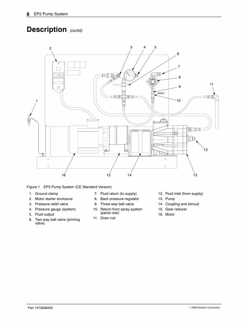
Description (contd)
7
8
9
543
6
2
1
16 15 14 13
12
10
11
Figure 1 EP2 Pump System (CE Standard Version)
1. Ground clamp2. Motor starter enclosure3. Pressure relief valve4. Pressure gauge (system)5. Fluid output6. Two-way ball valve (priming
valve)
7. Fluid return (to supply)8. Back pressure regulator9. Three-way ball valve
10. Return from spray system(panel rear)
11. Drain rod
12. Fluid inlet (from supply)13. Pump14. Coupling and shroud15. Gear reducer16. Motor
EP2 Pump System 9
Part 1072608A02� 2008 Nordson Corporation
1
2
3
4
6
5
7
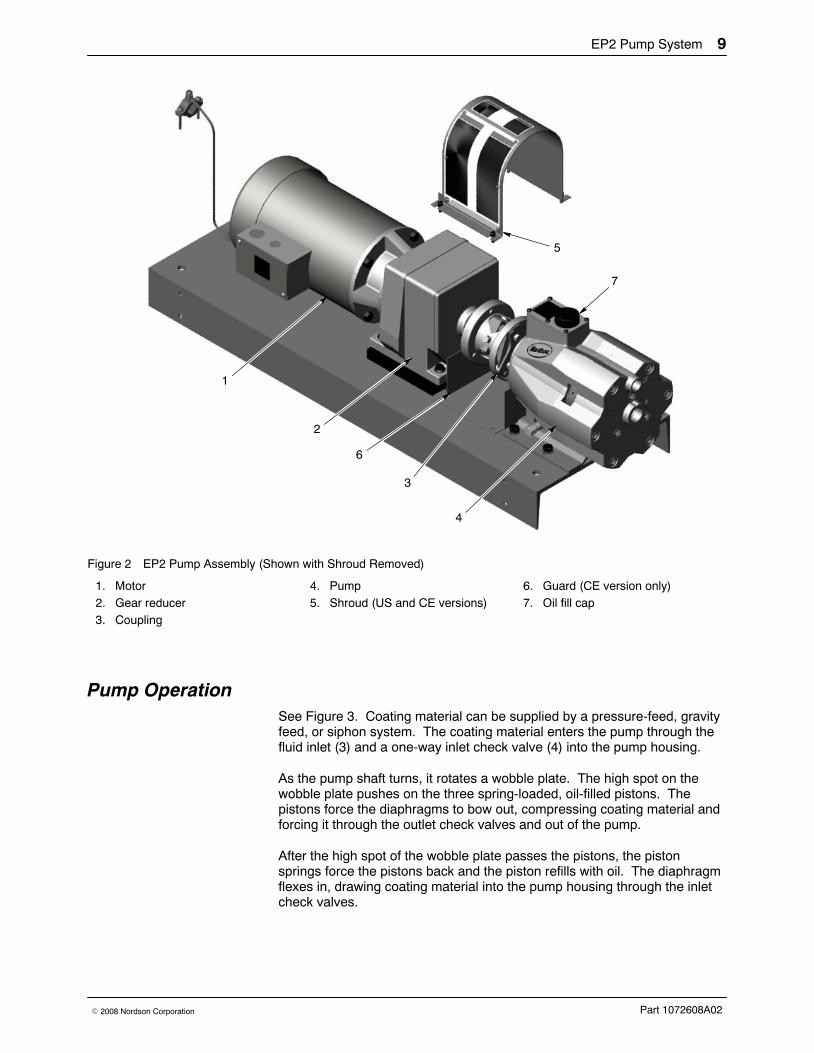
Figure 2 EP2 Pump Assembly (Shown with Shroud Removed)
1. Motor2. Gear reducer3. Coupling
4. Pump5. Shroud (US and CE versions)
6. Guard (CE version only)7. Oil fill cap
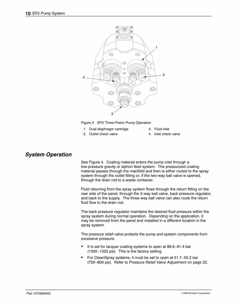
Pump Operation See Figure 3. Coating material can be supplied by a pressure-feed, gravityfeed, or siphon system. The coating material enters the pump through thefluid inlet (3) and a one-way inlet check valve (4) into the pump housing.
As the pump shaft turns, it rotates a wobble plate. The high spot on thewobble plate pushes on the three spring-loaded, oil-filled pistons. Thepistons force the diaphragms to bow out, compressing coating material andforcing it through the outlet check valves and out of the pump.
After the high spot of the wobble plate passes the pistons, the pistonsprings force the pistons back and the piston refills with oil. The diaphragmflexes in, drawing coating material into the pump housing through the inletcheck valves.
EP2 Pump System10
Part 1072608A02 � 2008 Nordson Corporation
1
24
3
Figure 3 EP2 Three-Piston Pump Operation
1. Dual-diaphragm cartridge2. Outlet check valve
3. Fluid inlet4. Inlet check valve
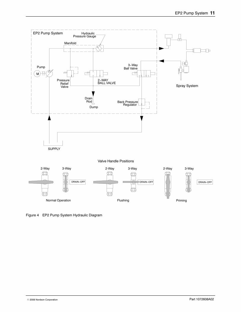
System Operation See Figure 4. Coating material enters the pump inlet through alow-pressure gravity or siphon feed system. The pressurized coatingmaterial passes through the manifold and then is either routed to the spraysystem through the outlet fitting or, if the two-way ball valve is opened,through the drain rod to a waste container.
Fluid returning from the spray system flows through the return fitting on therear side of the panel, through the 3-way ball valve, back pressure regulator,and back to the supply. The three-way ball valve can also route the returnfluid flow to the drain rod.
The back pressure regulator maintains the desired fluid pressure within thespray system during normal operation. Depending on the application, itmay be removed from the panel and installed in a different location in thespray system.
The pressure relief valve protects the pump and system components fromexcessive pressure.
� It is set for lacquer coating systems to open at 89.6−91.4 bar(1300−1325 psi). This is the factory setting.
� For CleanSpray systems, it must be set to open at 51.7−55.2 bar(750−800 psi). Refer to Pressure Relief Valve Adjustment on page 22.
EP2 Pump System 11
Part 1072608A02� 2008 Nordson Corporation
M
Dump
BALL VALVERelief
Manifold
HydraulicPressure Gauge
3−WayBall Valve
Back PressureRegulator
DrainRod
SUPPLY
Valve
2−WAY
DRAIN−OFF
Normal Operation Flushing
DRAIN−OFF
Priming
DRAIN−OFF
Valve Handle Positions
Spray System
EP2 Pump System
2-Way 3-Way 2-Way 3-Way 2-Way 3-Way
Pump
Pressure
Figure 4 EP2 Pump System Hydraulic Diagram
EP2 Pump System12
Part 1072608A02 � 2008 Nordson Corporation
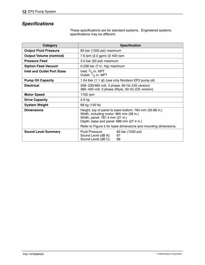
Specifications These specifications are for standard systems. Engineered systemsspecifications may be different.
Category Specification
Output Fluid Pressure 83 bar (1200 psi) maximum
Output Volume (nominal) 7.6 lpm (2.0 gpm) @ 400 rpm
Pressure Feed 3.5 bar (50 psi) maximum
Siphon Feed Vacuum 0.238 bar (7 in. Hg) maximum
Inlet and Outlet Port Sizes Inlet: 3/4 in. NPTOutlet: 1/2 in. NPT
Pump Oil Capacity 1.04 liter (1.1 qt) (use only Nordson EP2 pump oil)
Electrical 208−230/460 volt, 3 phase, 60 Hz (US version)380−420 volt, 3 phase (Wye), 50 Hz (CE version)
Motor Speed 1725 rpm
Drive Capacity 2.0 hp
System Weight 68 kg (150 lb)
Dimensions Height, top of panel to base bottom: 784 mm (30.86 in.)Width, including motor: 965 mm (38 in.)Width, panel: 787.4 mm (31 in.)Depth, base and panel: 696 mm (27.4 in.)
Refer to Figure 5 for base dimensions and mounting dimensions.
Sound Level Summary Fluid Pressure: 83 bar (1200 psi)Sound Level (dB A): 67Sound Level (dB C): 68
EP2 Pump System 13
Part 1072608A02� 2008 Nordson Corporation
Installation WARNING: Allow only qualified personnel to perform the following tasks.Follow the safety instructions in this document and all other relateddocumentation.
Oil Change Kit Installation The pump is shipped filled with oil. If you ordered an optional oil change kit,part 179490, install the quick-disconnect fitting included in the kit on the oildrain tube on the left side of the pump.
To do this without losing oil from the pump and making a mess, turn thesystem on its side with the oil drain tube up, unscrew the drain cap from thetube and install the quick-disconnect fitting on the tube.
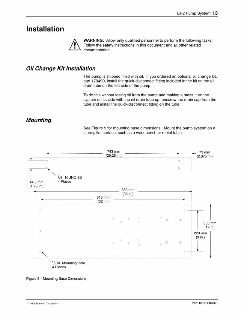
Mounting See Figure 5 for mounting base dimensions. Mount the pump system on asturdy, flat surface, such as a work bench or metal table.
743 mm(29.25 in.)
44.5 mm(1.75 in.)
73 mm(2.875 in.)
889 mm(35 in.)
305 mm(12 in.)
3/8−16UNC-2B4 Places
229 mm(9 in.)
813 mm(32 in.)
1/2 in. Mounting Hole4 Places
Figure 5 Mounting Base Dimensions
EP2 Pump System14
Part 1072608A02 � 2008 Nordson Corporation
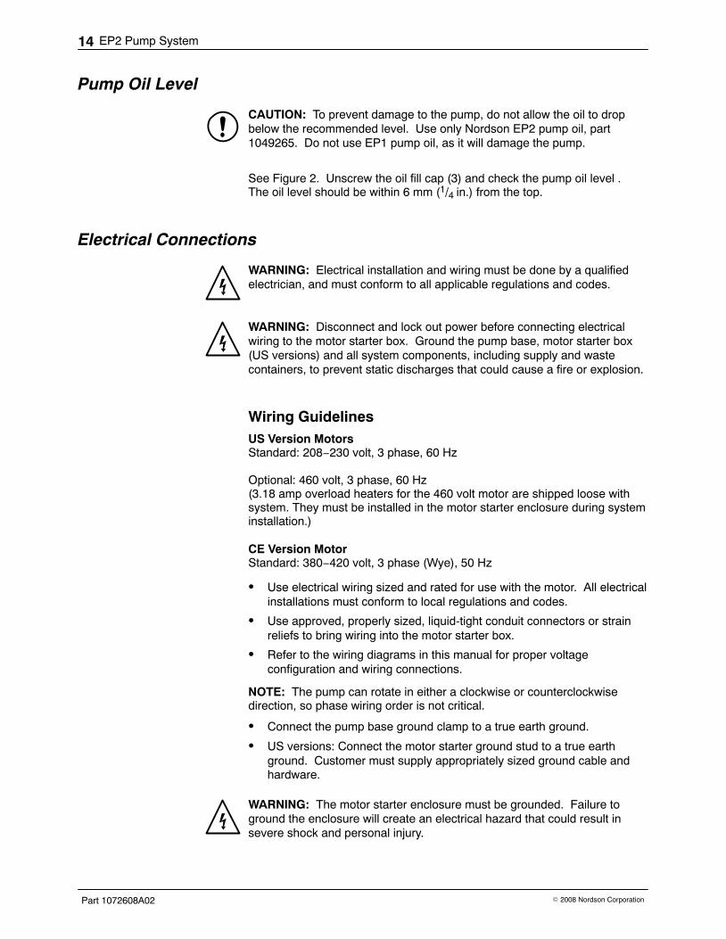
Pump Oil Level
CAUTION: To prevent damage to the pump, do not allow the oil to dropbelow the recommended level. Use only Nordson EP2 pump oil, part1049265. Do not use EP1 pump oil, as it will damage the pump.
See Figure 2. Unscrew the oil fill cap (3) and check the pump oil level .The oil level should be within 6 mm (1/4 in.) from the top.
Electrical Connections
WARNING: Electrical installation and wiring must be done by a qualifiedelectrician, and must conform to all applicable regulations and codes.
WARNING: Disconnect and lock out power before connecting electricalwiring to the motor starter box. Ground the pump base, motor starter box(US versions) and all system components, including supply and wastecontainers, to prevent static discharges that could cause a fire or explosion.
Wiring Guidelines US Version MotorsStandard: 208−230 volt, 3 phase, 60 Hz
Optional: 460 volt, 3 phase, 60 Hz(3.18 amp overload heaters for the 460 volt motor are shipped loose withsystem. They must be installed in the motor starter enclosure during systeminstallation.)
CE Version MotorStandard: 380−420 volt, 3 phase (Wye), 50 Hz
� Use electrical wiring sized and rated for use with the motor. All electricalinstallations must conform to local regulations and codes.
� Use approved, properly sized, liquid-tight conduit connectors or strainreliefs to bring wiring into the motor starter box.
� Refer to the wiring diagrams in this manual for proper voltageconfiguration and wiring connections.
NOTE: The pump can rotate in either a clockwise or counterclockwisedirection, so phase wiring order is not critical.
� Connect the pump base ground clamp to a true earth ground.
� US versions: Connect the motor starter ground stud to a true earthground. Customer must supply appropriately sized ground cable andhardware.
WARNING: The motor starter enclosure must be grounded. Failure toground the enclosure will create an electrical hazard that could result insevere shock and personal injury.
EP2 Pump System 15
Part 1072608A02� 2008 Nordson Corporation
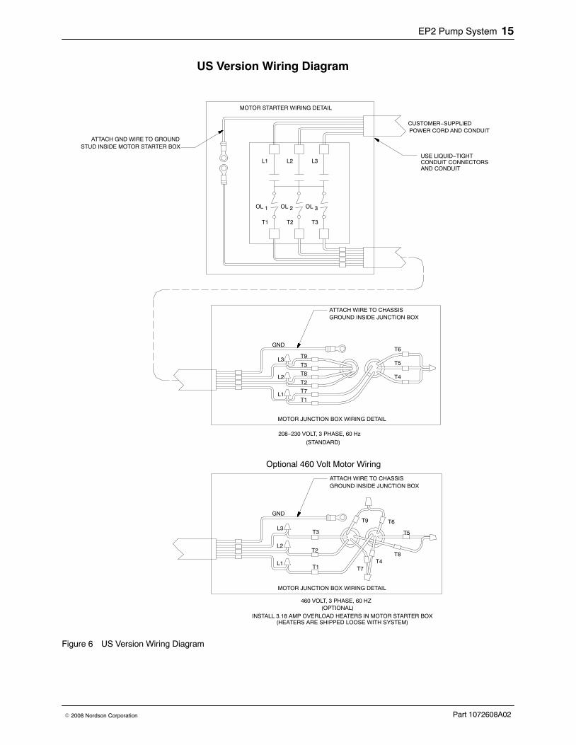
US Version Wiring Diagram
GND
L3
L2
L1
T9
T8
T7
T3
T2
T1
T5
T4
T6
MOTOR JUNCTION BOX WIRING DETAIL
ATTACH WIRE TO CHASSISGROUND INSIDE JUNCTION BOX
T2 T3
OL
T1
1 OL 2 OL 3
L1 L2 L3
ATTACH GND WIRE TO GROUNDSTUD INSIDE MOTOR STARTER BOX
MOTOR STARTER WIRING DETAIL
POWER CORD AND CONDUIT
(STANDARD)
208−230 VOLT, 3 PHASE, 60 Hz
CUSTOMER−SUPPLIED
USE LIQUID−TIGHTCONDUIT CONNECTORSAND CONDUIT
GND
L3
L2
L1
T9
T8
T7
T3
T2
T1
T5
T4
T6
MOTOR JUNCTION BOX WIRING DETAIL
ATTACH WIRE TO CHASSISGROUND INSIDE JUNCTION BOX
460 VOLT, 3 PHASE, 60 HZ(OPTIONAL)
INSTALL 3.18 AMP OVERLOAD HEATERS IN MOTOR STARTER BOX(HEATERS ARE SHIPPED LOOSE WITH SYSTEM)
Optional 460 Volt Motor Wiring
Figure 6 US Version Wiring Diagram
EP2 Pump System16
Part 1072608A02 � 2008 Nordson Corporation
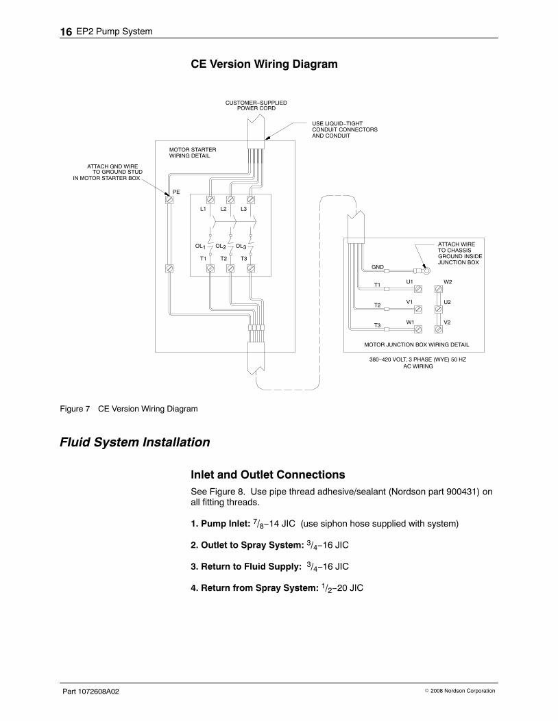
CE Version Wiring Diagram
GND
MOTOR JUNCTION BOX WIRING DETAIL
ATTACH WIRETO CHASSISGROUND INSIDEJUNCTION BOX
T2 T3
OL
T1
1 OL2 OL3
L1 L2 L3
ATTACH GND WIRE
MOTOR STARTER
CUSTOMER−SUPPLIED
AC WIRING380−420 VOLT, 3 PHASE (WYE) 50 HZ
WIRING DETAIL
T1
T2
T3W1
V1
U1 W2
U2
V2
PE
POWER CORD
TO GROUND STUDIN MOTOR STARTER BOX
USE LIQUID−TIGHTCONDUIT CONNECTORSAND CONDUIT
Figure 7 CE Version Wiring Diagram
Fluid System Installation
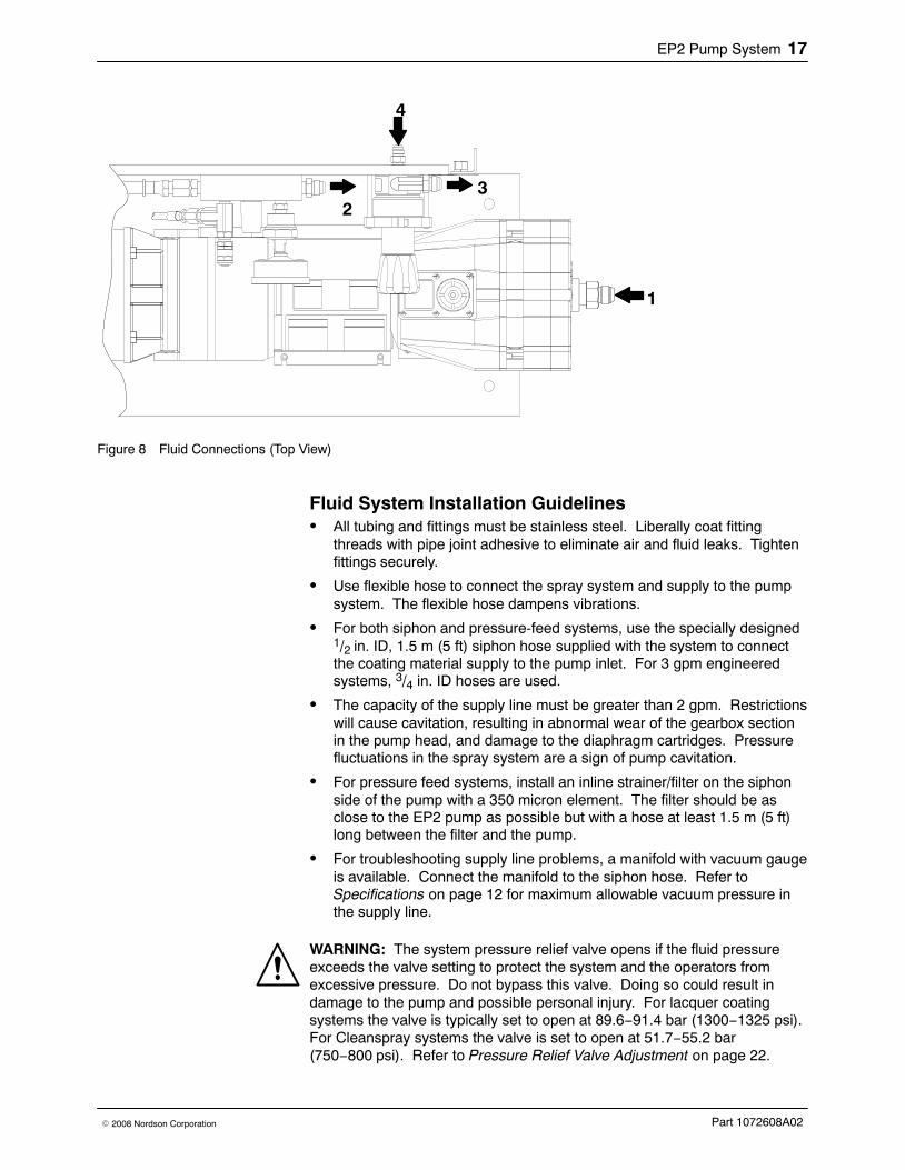
Inlet and Outlet Connections See Figure 8. Use pipe thread adhesive/sealant (Nordson part 900431) onall fitting threads.
1. Pump Inlet: 7/8−14 JIC (use siphon hose supplied with system)
2. Outlet to Spray System: 3/4−16 JIC
3. Return to Fluid Supply: 3/4−16 JIC
4. Return from Spray System: 1/2−20 JIC
EP2 Pump System 17
Part 1072608A02� 2008 Nordson Corporation
1
23
4
Figure 8 Fluid Connections (Top View)
Fluid System Installation Guidelines� All tubing and fittings must be stainless steel. Liberally coat fitting
threads with pipe joint adhesive to eliminate air and fluid leaks. Tightenfittings securely.
� Use flexible hose to connect the spray system and supply to the pumpsystem. The flexible hose dampens vibrations.
� For both siphon and pressure-feed systems, use the specially designed1/2 in. ID, 1.5 m (5 ft) siphon hose supplied with the system to connectthe coating material supply to the pump inlet. For 3 gpm engineeredsystems, 3/4 in. ID hoses are used.
� The capacity of the supply line must be greater than 2 gpm. Restrictionswill cause cavitation, resulting in abnormal wear of the gearbox sectionin the pump head, and damage to the diaphragm cartridges. Pressurefluctuations in the spray system are a sign of pump cavitation.
� For pressure feed systems, install an inline strainer/filter on the siphonside of the pump with a 350 micron element. The filter should be asclose to the EP2 pump as possible but with a hose at least 1.5 m (5 ft)long between the filter and the pump.
� For troubleshooting supply line problems, a manifold with vacuum gaugeis available. Connect the manifold to the siphon hose. Refer toSpecifications on page 12 for maximum allowable vacuum pressure inthe supply line.
WARNING: The system pressure relief valve opens if the fluid pressureexceeds the valve setting to protect the system and the operators fromexcessive pressure. Do not bypass this valve. Doing so could result indamage to the pump and possible personal injury. For lacquer coatingsystems the valve is typically set to open at 89.6−91.4 bar (1300−1325 psi).For Cleanspray systems the valve is set to open at 51.7−55.2 bar(750−800 psi). Refer to Pressure Relief Valve Adjustment on page 22.
EP2 Pump System18
Part 1072608A02 � 2008 Nordson Corporation
Operation WARNING: Allow only qualified personnel to perform the following tasks.Follow the safety instructions in this document and all other relateddocumentation.
New systems must be purged of contaminates by flushing with a solventcompatible with the coating material before starting production.
CAUTION: Make sure your coating materials and solvents are compatiblewith the diaphragms and seals in the EP2 pump. Some coating materialsand solvents can damage the diaphragms and seals. Your Nordsonrepresentative can provide you with information on compatible materials.
System Startup Step Task Procedure
1 Pump Priming 1. Place the drain rod in a waste container.
2. Turn the back pressure regulator knob fullycounter-clockwise.
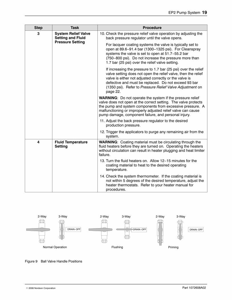
3. See Figure 9. Turn the ball valves to the priming position.
4. Supply coating material to the EP2 pump.
5. Turn on the EP2 pump.
6. Watch the drain rod. When a solid stream of coatingmaterial is flowing from the rod with no air bubbles,perform the Air Purge Procedure.
2 Air Purge 7. See Figure 9. Turn the ball valves to the flushing position.
8. Watch the drain rod. When a solid stream of coatingmaterial is flowing from the rod with no air bubbles, turnthe ball valves to the normal operation position.
9. Trigger the applicators to purge them of air. Air in the gunbodies and system will cause them to spit. When they stopspitting the system should be completely purged of air.
NOTE: If the pump is operating roughly, air in the system iscausing the pump to cavitate. Repeat the air purgeprocedure. If you cannot purge the system of air, check thesiphon hoses and fittings supplying the pump with fluid. A leakin the supply line will suck air into the pump.
Continued...
EP2 Pump System 19
Part 1072608A02� 2008 Nordson Corporation
ProcedureTaskStep
3 System Relief ValveSetting and FluidPressure Setting
10. Check the pressure relief valve operation by adjusting theback pressure regulator until the valve opens.
For lacquer coating systems the valve is typically set toopen at 89.6−91.4 bar (1300−1325 psi). For Cleanspraysystems the valve is set to open at 51.7−55.2 bar(750−800 psi). Do not increase the pressure more than1.7 bar (25 psi) over the relief valve setting.
If increasing the pressure to 1.7 bar (25 psi) over the reliefvalve setting does not open the relief valve, then the reliefvalve is either not adjusted correctly or the valve isdefective and must be replaced. Do not exceed 93 bar(1350 psi). Refer to Pressure Relief Valve Adjustment onpage 22.
WARNING: Do not operate the system if the pressure reliefvalve does not open at the correct setting. The valve protectsthe pump and system components from excessive pressure. Amalfunctioning or improperly adjusted relief valve can causepump damage, component failure, and personal injury.
11. Adjust the back pressure regulator to the desiredproduction pressure.
12. Trigger the applicators to purge any remaining air from thesystem.
4 Fluid TemperatureSetting
WARNING: Coating material must be circulating through thefluid heaters before they are turned on. Operating the heaterswithout circulation can result in heater plugging and heat limiterfailure.
13. Turn the fluid heaters on. Allow 12−15 minutes for thecoating material to heat to the desired operatingtemperature.
14. Check the system thermometer. If the coating material isnot within 5 degrees of the desired temperature, adjust theheater thermostats. Refer to your heater manual forprocedures.
DRAIN−OFF
Normal Operation Flushing
DRAIN−OFF
Priming
DRAIN−OFF
2-Way 3-Way 2-Way 3-Way 2-Way 3-Way
Figure 9 Ball Valve Handle Positions
EP2 Pump System20
Part 1072608A02 � 2008 Nordson Corporation
Changing Coating Materials/Flushing the System Use the tasks in the System Startup chart as required when changingmaterials.
Depending on your coating materials and application, you may be able tochange coating materials by letting the new coating material push the oldmaterial out of the system, or you may have to flush the system with solventbefore introducing the new material.
If the new coating material is not compatible with the old material, flush thesystem two times with solvent:
� First solvent flush: Use a solvent that is compatible with the old material.
� Second solvent flush: Use a solvent that is compatible with the newmaterial.
Refer to the System Startup Procedures on page 18.
1. Turn the back pressure regulator knob fully counterclockwise tode-pressurize the system.
2. Turn off the EP2 pump.
3. If used, shut off the pressure feed.
4. Trigger the applicators.
5. Supply the system with solvent or new coating material.
6. Turn the ball valves to the priming position and start the pump. Whenair stops flowing from the drain valve, turn the ball valves to the flushingposition and flush the old material and air out of the system.
7. Trigger the applicators to purge them of old material and air.
8. Set the fluid pressure and temperature as necessary.
EP2 Pump System 21
Part 1072608A02� 2008 Nordson Corporation
Shutdown
CAUTION: To prevent coating material failure and damage to the system,do not operate the pump at a high rpm for long periods of time withoutactuating the applicators.
Short-Term Shutdown1. If used, turn off the fluid heaters 12−15 minutes prior to shutdown. Refer
to the heater manual for procedures.
2. Turn the back pressure regulator knob fully counterclockwise tode-pressurize the system.
3. Turn off the EP2 pump.
4. If used, shut off the pressure feed.
Long-Term Shutdown
CAUTION: To prevent damage to the fluid diaphragms and seals, consult aNordson representative for types of solvents that can be left in the systemfor long periods of time.
1. If used, turn off the fluid heaters 12−15 min prior to shutdown. Refer tothe heater manual for procedures.
2. Flush the system with a solvent compatible with the coating material.
3. Turn the back pressure regulator knob fully counterclockwise tode-pressurize the system.
4. Turn off the EP2 pump.
5. Remove and clean the applicator nozzles.
EP2 Pump System22
Part 1072608A02 � 2008 Nordson Corporation
Pressure Relief Valve Adjustment
WARNING: System pressurized! Use extreme care when makingadjustments. The system pressure relief valve opens if the fluid pressureexceeds the valve setting to protect the system and the operators fromexcessive pressure. If the relief valve fails to operate correctly, replace itimmediately. Do not operate the system without a correctly functioning reliefvalve.
Pressure relief valve opening pressure (factory setting)
� lacquer coating systems: 89−91.4 bar (1300−1325 psi)
� CleanSpray systems: 51.7−55.2 bar (750−800 psi).
Use this procedure to adjust the valve opening pressure and check thevalve operation.
1. Adjust the back pressure regulator until the system fluid pressure is atthe factory setting given above.
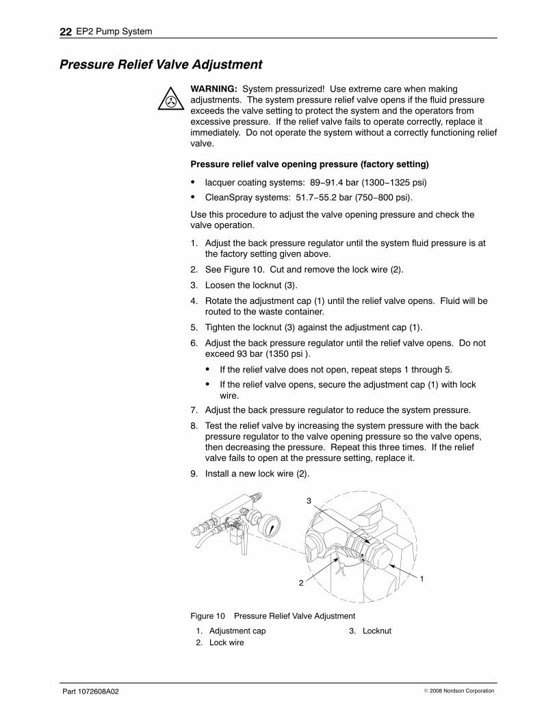
2. See Figure 10. Cut and remove the lock wire (2).
3. Loosen the locknut (3).
4. Rotate the adjustment cap (1) until the relief valve opens. Fluid will berouted to the waste container.
5. Tighten the locknut (3) against the adjustment cap (1).
6. Adjust the back pressure regulator until the relief valve opens. Do notexceed 93 bar (1350 psi ).
� If the relief valve does not open, repeat steps 1 through 5.
� If the relief valve opens, secure the adjustment cap (1) with lockwire.
7. Adjust the back pressure regulator to reduce the system pressure.
8. Test the relief valve by increasing the system pressure with the backpressure regulator to the valve opening pressure so the valve opens,then decreasing the pressure. Repeat this three times. If the reliefvalve fails to open at the pressure setting, replace it.
9. Install a new lock wire (2).
12
3
Figure 10 Pressure Relief Valve Adjustment
1. Adjustment cap2. Lock wire
3. Locknut
EP2 Pump System 23
Part 1072608A02� 2008 Nordson Corporation
Maintenance WARNING: Allow only qualified personnel to perform the following tasks.Follow the safety instructions in this document and all other relateddocumentation.
EP2 Pump Oil Change Frequency: After the first 100 hours of operation, then every 1000 hours.Capacity: The pump holds between 1 and 2 quarts of oil. Oil is sold in 2quart bottles. Refer to Parts for the part number.
NOTE: To reduce the oil change time, order the optional quick oil changekit. Refer to Options for the kit part number.
1. Turn the pump on and run it until the oil is warm.
2. Turn the pump off.
3. Place a pan under the pump drain tube.
CAUTION: To prevent losing the oil prime in the piston assemblies, do notrotate the pump shaft during routine oil changes.
4. Drain the oil from the pump housing:
Without Optional Oil Change Kit
With Optional Oil Change Kit
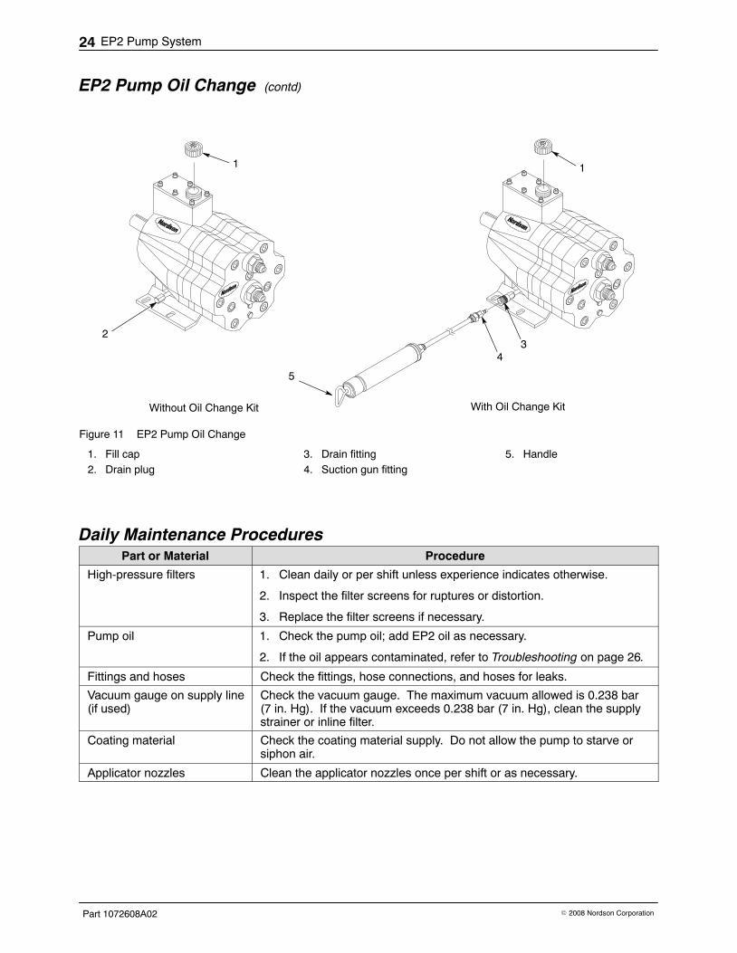
a. See Figure 11. Remove the oilfill cap (1) from the pump.
b. Remove the drain cap (2).
c. Replace the drain cap after theoil has drained.
a. See Figure 11. Remove the oilfill cap (1) from the pump.
b. Connect the malequick-disconnect fitting (4) tothe female quick-disconnectfitting (3) on the drain tube.The female fitting is includedwith the oil change kit andshould be installed on the draintube in place of the drain cap.
c. Draw the oil out of the pumpwith the suction gun (5). Emptythe oil into a waste container.Repeat until the pump is empty.
d. Disconnect the suction gunfitting from the drain fitting.
5. Fill the pump with new EP2 pump oil to within 6 mm (1/4 in.) from the top.Install the fill cap.
EP2 Pump System24
Part 1072608A02 � 2008 Nordson Corporation
EP2 Pump Oil Change (contd)
1
34
5
2
1
Without Oil Change Kit With Oil Change Kit
Figure 11 EP2 Pump Oil Change
1. Fill cap2. Drain plug
3. Drain fitting4. Suction gun fitting
5. Handle
Daily Maintenance Procedures Part or Material Procedure
High-pressure filters 1. Clean daily or per shift unless experience indicates otherwise.
2. Inspect the filter screens for ruptures or distortion.
3. Replace the filter screens if necessary.
Pump oil 1. Check the pump oil; add EP2 oil as necessary.
2. If the oil appears contaminated, refer to Troubleshooting on page 26.
Fittings and hoses Check the fittings, hose connections, and hoses for leaks.
Vacuum gauge on supply line(if used)
Check the vacuum gauge. The maximum vacuum allowed is 0.238 bar(7 in. Hg). If the vacuum exceeds 0.238 bar (7 in. Hg), clean the supplystrainer or inline filter.
Coating material Check the coating material supply. Do not allow the pump to starve orsiphon air.
Applicator nozzles Clean the applicator nozzles once per shift or as necessary.
EP2 Pump System 25
Part 1072608A02� 2008 Nordson Corporation
Monthly Maintenance Procedures Part or Material Procedure
Strainer or inline supply filter Clean the strainer or inline supply filter.
Pump coupling Check the pump coupling for loose hardware or wear.
Pressure relief valve Check the pressure relief valve by following these steps:
1. Turn off the applicators.
2. Make sure the drain-off rod is in the waste container.
WARNING: Do not exceed 93 bar (1350 psi).
3. Turn the back pressure regulator knob clockwise until the openingpressure (refer to page 22) is reached. If the valve does not open,adjust it as described in Pressure Relief Valve Adjustment onpage 22.
4. Turn the back pressure regulator knob counterclockwise to reduce thepressure.
5. Repeat steps 4 and 5 a minimum of three times to ensure the valve isoperating properly.
Annual Maintenance Procedures Refer to the EP2 Three-Piston Pump manual for disassembly and repairprocedures:
� Examine the shaft seals and piston assemblies in the oil-filled section.Replace if worn.
� Examine the cam shaft bearings in the oil-filled section. Replace thepump if the bearings are worn.
� Replace the diaphragm cartridges and valve assemblies.
EP2 Pump System26
Part 1072608A02 � 2008 Nordson Corporation
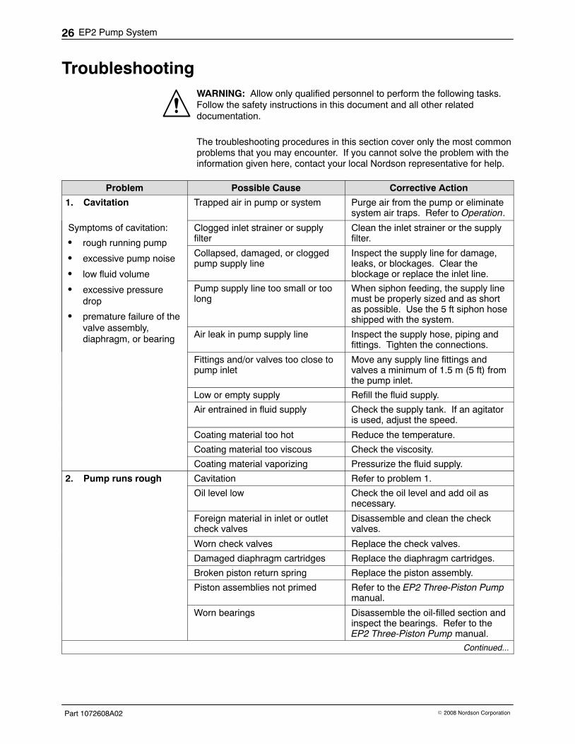
Troubleshooting WARNING: Allow only qualified personnel to perform the following tasks.Follow the safety instructions in this document and all other relateddocumentation.
The troubleshooting procedures in this section cover only the most commonproblems that you may encounter. If you cannot solve the problem with theinformation given here, contact your local Nordson representative for help.
Problem Possible Cause Corrective Action
1. Cavitation Trapped air in pump or system Purge air from the pump or eliminatesystem air traps. Refer to Operation.
Symptoms of cavitation:
� rough running pump
� excessive pump noise
� low fluid volume
� excessive pressuredrop
� premature failure of thevalve assembly,diaphragm, or bearing
Clogged inlet strainer or supplyfilter
Clean the inlet strainer or the supplyfilter.
Collapsed, damaged, or cloggedpump supply line
Inspect the supply line for damage,leaks, or blockages. Clear theblockage or replace the inlet line.
Pump supply line too small or toolong
When siphon feeding, the supply linemust be properly sized and as shortas possible. Use the 5 ft siphon hoseshipped with the system.
Air leak in pump supply line Inspect the supply hose, piping andfittings. Tighten the connections.
Fittings and/or valves too close topump inlet
Move any supply line fittings andvalves a minimum of 1.5 m (5 ft) fromthe pump inlet.
Low or empty supply Refill the fluid supply.
Air entrained in fluid supply Check the supply tank. If an agitatoris used, adjust the speed.
Coating material too hot Reduce the temperature.
Coating material too viscous Check the viscosity.
Coating material vaporizing Pressurize the fluid supply.
2. Pump runs rough Cavitation Refer to problem 1.
Oil level low Check the oil level and add oil asnecessary.
Foreign material in inlet or outletcheck valves
Disassemble and clean the checkvalves.
Worn check valves Replace the check valves.
Damaged diaphragm cartridges Replace the diaphragm cartridges.
Broken piston return spring Replace the piston assembly.
Piston assemblies not primed Refer to the EP2 Three-Piston Pumpmanual.
Worn bearings Disassemble the oil-filled section andinspect the bearings. Refer to theEP2 Three-Piston Pump manual.
Continued...
EP2 Pump System 27
Part 1072608A02� 2008 Nordson Corporation
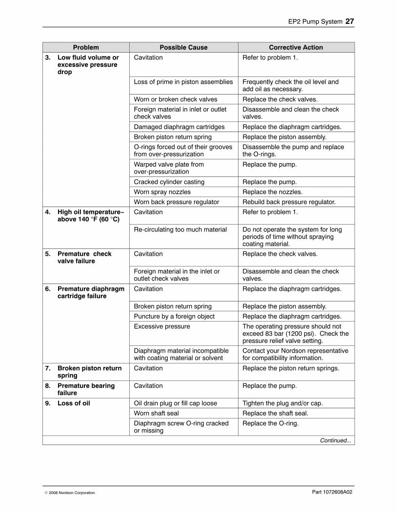
Problem Possible Cause Corrective Action
3. Low fluid volume orexcessive pressuredrop
Cavitation Refer to problem 1.
Loss of prime in piston assemblies Frequently check the oil level andadd oil as necessary.
Worn or broken check valves Replace the check valves.
Foreign material in inlet or outletcheck valves
Disassemble and clean the checkvalves.
Damaged diaphragm cartridges Replace the diaphragm cartridges.
Broken piston return spring Replace the piston assembly.
O-rings forced out of their groovesfrom over-pressurization
Disassemble the pump and replacethe O-rings.
Warped valve plate fromover-pressurization
Replace the pump.
Cracked cylinder casting Replace the pump.
Worn spray nozzles Replace the nozzles.
Worn back pressure regulator Rebuild back pressure regulator.
4. High oil temperature−above 140 F (60 C)
Cavitation Refer to problem 1.
Re-circulating too much material Do not operate the system for longperiods of time without sprayingcoating material.
5. Premature checkvalve failure
Cavitation Replace the check valves.
Foreign material in the inlet oroutlet check valves
Disassemble and clean the checkvalves.
6. Premature diaphragmcartridge failure
Cavitation Replace the diaphragm cartridges.
Broken piston return spring Replace the piston assembly.
Puncture by a foreign object Replace the diaphragm cartridges.
Excessive pressure The operating pressure should notexceed 83 bar (1200 psi). Check thepressure relief valve setting.
Diaphragm material incompatiblewith coating material or solvent
Contact your Nordson representativefor compatibility information.
7. Broken piston returnspring
Cavitation Replace the piston return springs.
8. Premature bearingfailure
Cavitation Replace the pump.
9. Loss of oil Oil drain plug or fill cap loose Tighten the plug and/or cap.
Worn shaft seal Replace the shaft seal.
Diaphragm screw O-ring crackedor missing
Replace the O-ring.
Continued...
EP2 Pump System28
Part 1072608A02 � 2008 Nordson Corporation
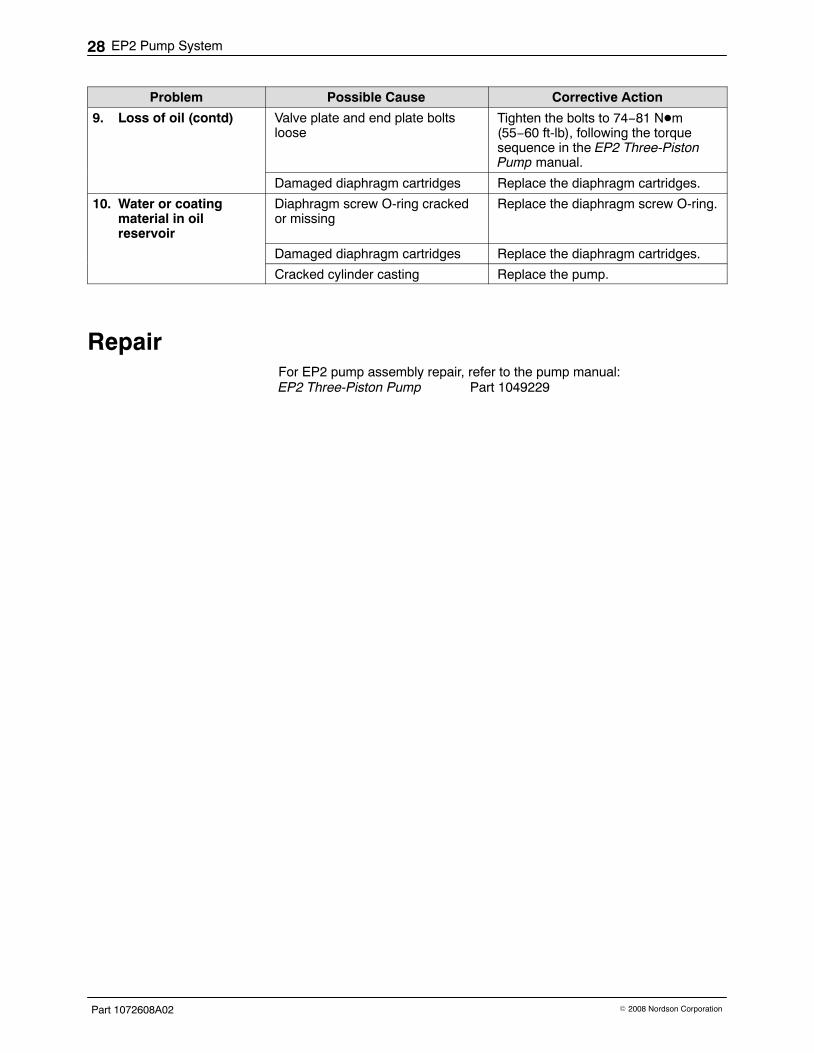
Corrective ActionPossible CauseProblem
9. Loss of oil (contd) Valve plate and end plate boltsloose
Tighten the bolts to 74−81 N�m(55−60 ft-lb), following the torquesequence in the EP2 Three-PistonPump manual.
Damaged diaphragm cartridges Replace the diaphragm cartridges.
10. Water or coatingmaterial in oilreservoir
Diaphragm screw O-ring crackedor missing
Replace the diaphragm screw O-ring.
Damaged diaphragm cartridges Replace the diaphragm cartridges.
Cracked cylinder casting Replace the pump.
Repair For EP2 pump assembly repair, refer to the pump manual:EP2 Three-Piston Pump Part 1049229
EP2 Pump System 29
Part 1072608A02� 2008 Nordson Corporation
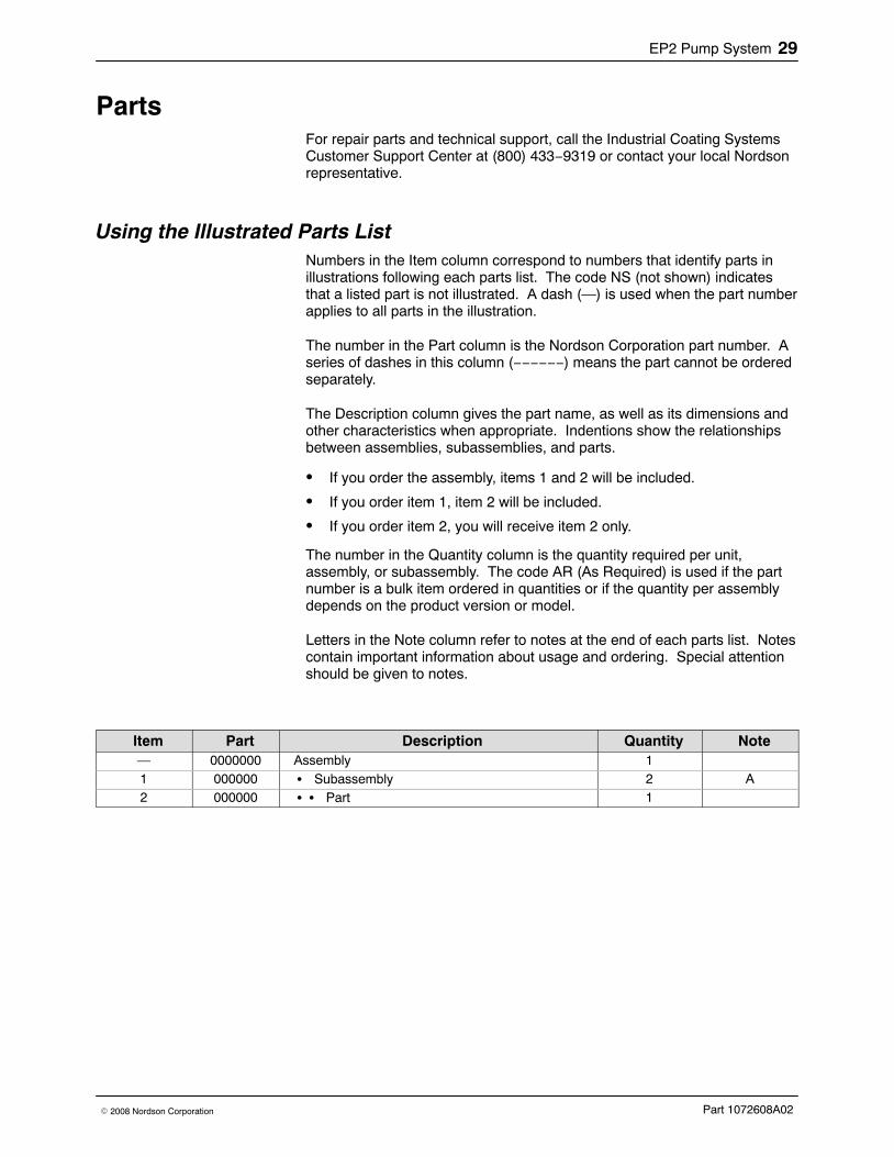
Parts For repair parts and technical support, call the Industrial Coating SystemsCustomer Support Center at (800) 433−9319 or contact your local Nordsonrepresentative.
Using the Illustrated Parts List Numbers in the Item column correspond to numbers that identify parts inillustrations following each parts list. The code NS (not shown) indicatesthat a listed part is not illustrated. A dash (—) is used when the part numberapplies to all parts in the illustration.
The number in the Part column is the Nordson Corporation part number. Aseries of dashes in this column (−−−−−−) means the part cannot be orderedseparately.
The Description column gives the part name, as well as its dimensions andother characteristics when appropriate. Indentions show the relationshipsbetween assemblies, subassemblies, and parts.
� If you order the assembly, items 1 and 2 will be included.
� If you order item 1, item 2 will be included.
� If you order item 2, you will receive item 2 only.
The number in the Quantity column is the quantity required per unit,assembly, or subassembly. The code AR (As Required) is used if the partnumber is a bulk item ordered in quantities or if the quantity per assemblydepends on the product version or model.
Letters in the Note column refer to notes at the end of each parts list. Notescontain important information about usage and ordering. Special attentionshould be given to notes.
Item Part Description Quantity Note— 0000000 Assembly 11 000000 � Subassembly 2 A2 000000 � � Part 1
EP2 Pump System30
Part 1072608A02 � 2008 Nordson Corporation
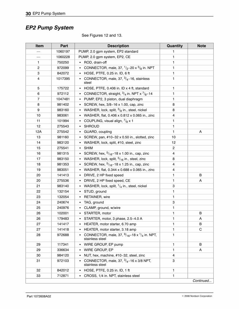
EP2 Pump System See Figures 12 and 13.
Item Part Description Quantity Note— 1060197 PUMP, 2.0 gpm system, EP2 standard 1
— 1060228 PUMP, 2.0 gpm system, EP2, CE 1
1 750250 � ROD, drain-off 1
2 972099 � CONNECTOR, male, 37, 1/2−20 x 3/8 in. NPT 1
3 842072 � HOSE, PTFE, 0.25 in. ID, 6 ft 1
4 1017395 � CONNECTOR, male, 37, 3/4−16, stainlesssteel
1
5 175722 � HOSE, PTFE, 0.406 in. ID x 4 ft, standard 1
6 972112 � CONNECTOR, straight, 3/4 in. NPT x 7/8−14 1
7 1047481 � PUMP, EP2, 3 piston, dual diaphragm 1
8 981402 � SCREW, hex, 3/8−16 x 1.00, cap, zinc 8
9 983160 � WASHER, lock, split, 3/8 in., steel, nickel 8
10 983061 � WASHER, flat, 0.406 x 0.812 x 0.065 in., zinc 4
11 101994 � COUPLING, visual align, 7/8 x 1 1
12 275543 � SHROUD 1
12A 275542 � GUARD, coupling 1 A
13 981160 � SCREW, pan, #10−32 x 0.50 in., slotted, zinc 10
14 983120 � WASHER, lock, split, #10, steel, zinc 12
15 275541 � SHIM 2
16 981315 � SCREW, hex, 5/16−18 x 1.00 in., cap, zinc 4
17 983150 � WASHER, lock, split, 5/16 in., steel, zinc 8
18 981353 � SCREW, hex, 5/16−18 x 1.25 in., cap, zinc 4
19 983051 � WASHER, flat, 0.344 x 0.688 x 0.065 in., zinc 4
20 141413 � DRIVE, 2 HP fixed speed 1 B
20 275536 � DRIVE, 2 HP fixed speed, CE 1 A
21 983140 � WASHER, lock, split, 1/4 in., steel, nickel 3
22 132154 � STUD, ground 1
23 132054 � RETAINER, wire 1
24 240674 � TAG, ground 3
25 240976 � CLAMP, ground, w/wire 1
26 102001 � STARTER, motor 1 B
26 179483 � STARTER, motor, 3 phase, 2.5−4.0 A 1 A
27 141417 � HEATER, motor starter, 6.70 amp 1 B
27 141418 � HEATER, motor starter, 3.18 amp 1 C
28 972688 � CONNECTOR, male, 37, 9/16−18 x 1/4 in. NPT,stainless steel
1
29 117341 � WIRE GROUP, EP pump 1 B
29 336634 � WIRE GROUP, EP 1 A
30 984120 � NUT, hex, machine, #10−32, steel, zinc 4
31 972103 � CONNECTOR, male, 37, 3/4−16 x 3/8 NPT,stainless steel
3
32 842012 � HOSE, PTFE, 0.25 in. ID, 1 ft 1
33 712871 � CROSS, 1/4 in. NPT, stainless steel 1Continued...
EP2 Pump System 31
Part 1072608A02� 2008 Nordson Corporation
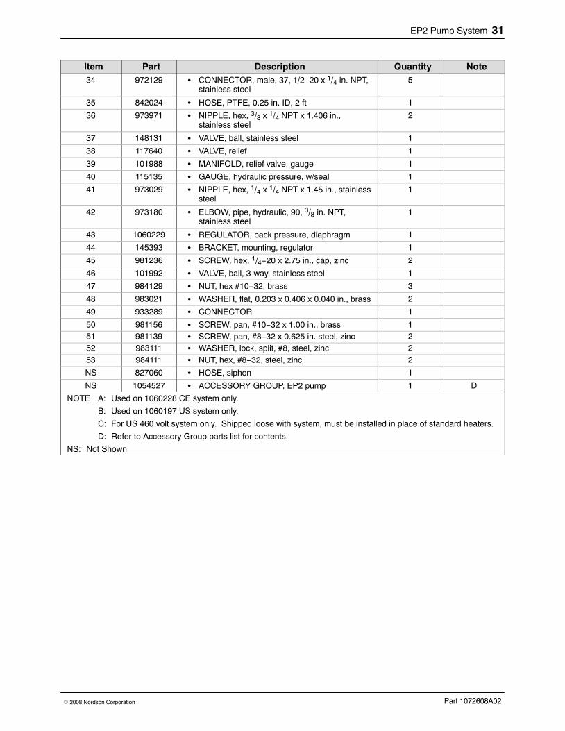
NoteQuantityDescriptionPartItem34 972129 � CONNECTOR, male, 37, 1/2−20 x 1/4 in. NPT,
stainless steel5
35 842024 � HOSE, PTFE, 0.25 in. ID, 2 ft 1
36 973971 � NIPPLE, hex, 3/8 x 1/4 NPT x 1.406 in.,stainless steel
2
37 148131 � VALVE, ball, stainless steel 1
38 117640 � VALVE, relief 1
39 101988 � MANIFOLD, relief valve, gauge 1
40 115135 � GAUGE, hydraulic pressure, w/seal 1
41 973029 � NIPPLE, hex, 1/4 x 1/4 NPT x 1.45 in., stainlesssteel
1
42 973180 � ELBOW, pipe, hydraulic, 90, 3/8 in. NPT,stainless steel
1
43 1060229 � REGULATOR, back pressure, diaphragm 1
44 145393 � BRACKET, mounting, regulator 1
45 981236 � SCREW, hex, 1/4−20 x 2.75 in., cap, zinc 2
46 101992 � VALVE, ball, 3-way, stainless steel 1
47 984129 � NUT, hex #10−32, brass 3
48 983021 � WASHER, flat, 0.203 x 0.406 x 0.040 in., brass 2
49 933289 � CONNECTOR 1
50 981156 � SCREW, pan, #10−32 x 1.00 in., brass 151 981139 � SCREW, pan, #8−32 x 0.625 in. steel, zinc 252 983111 � WASHER, lock, split, #8, steel, zinc 253 984111 � NUT, hex, #8−32, steel, zinc 2
NS 827060 � HOSE, siphon 1
NS 1054527 � ACCESSORY GROUP, EP2 pump 1 D
NOTE A: Used on 1060228 CE system only.
B: Used on 1060197 US system only.
C: For US 460 volt system only. Shipped loose with system, must be installed in place of standard heaters.
D: Refer to Accessory Group parts list for contents.
NS: Not Shown
EP2 Pump System32
Part 1072608A02 � 2008 Nordson Corporation
4
1
6
8
2
3
25
26
5
7
910
12
1314
15
1617
171819
20
11
21222324
31
2728
SeeFigure 13for CE Parts
Detail A(US Version Only)
See Detail A(US Version Only)
131430
29
32
3334 35
3436
37
38
131439
40
31
41
42
31
43
214445 36
4634
47
24
4747
49
501448
24Ground from Motor
28
1448
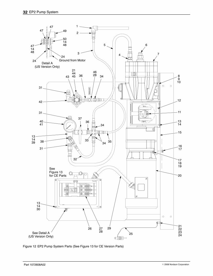
Figure 12 EP2 Pump System Parts (See Figure 13 for CE Version Parts)
EP2 Pump System 33
Part 1072608A02� 2008 Nordson Corporation
12A
26
20
515253
29
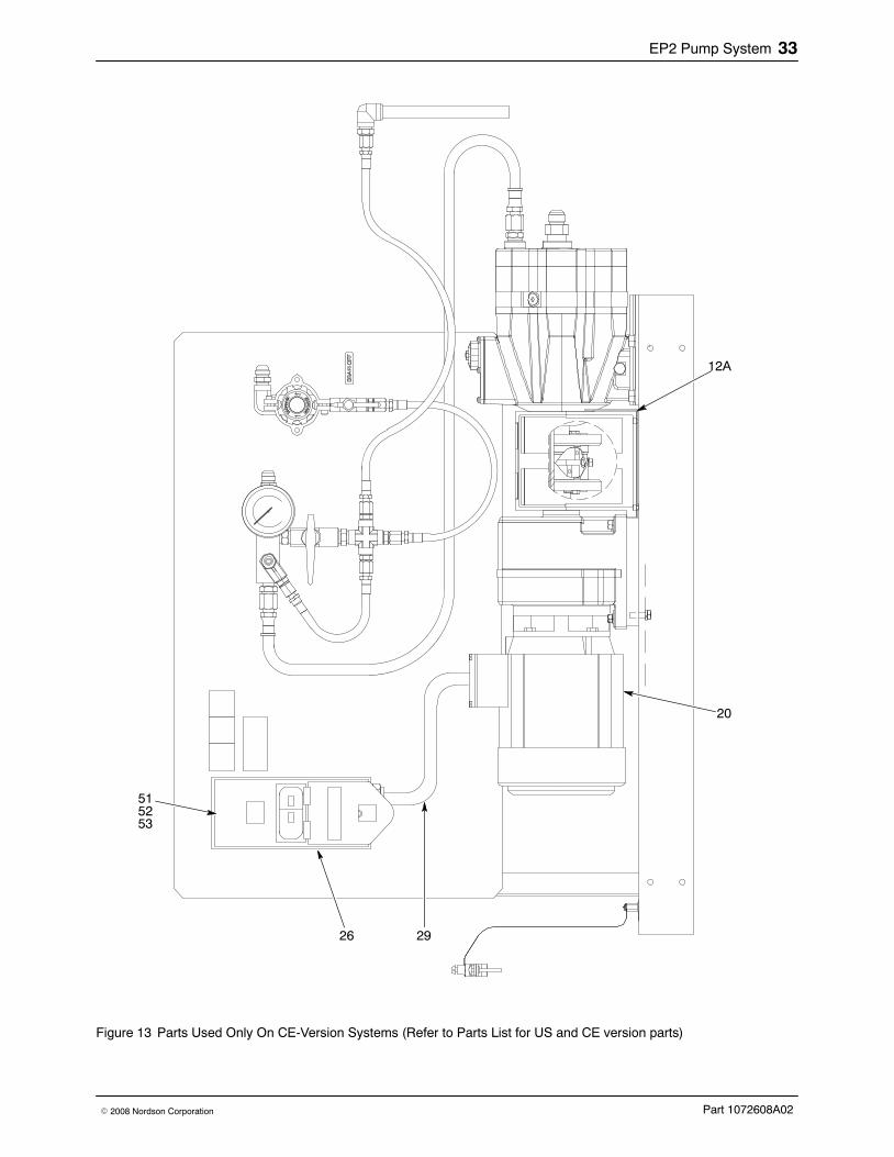
Figure 13 Parts Used Only On CE-Version Systems (Refer to Parts List for US and CE version parts)
EP2 Pump System34
Part 1072608A02 � 2008 Nordson Corporation
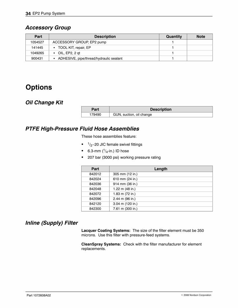
Accessory Group
Part Description Quantity Note1054527 ACCESSORY GROUP, EP2 pump 1
141445 � TOOL KIT, repair, EP 1
1049265 � OIL, EP2, 2 qt 1
900431 � ADHESIVE, pipe/thread/hydraulic sealant 1
Options
Oil Change KitPart Description
179490 GUN, suction, oil change
PTFE High-Pressure Fluid Hose AssembliesThese hose assemblies feature:
� 1/2−20 JIC female swivel fittings
� 6.3-mm (1/4-in.) ID hose
� 207 bar (3000 psi) working pressure rating
Part Length842012 305 mm (12 in.)842024 610 mm (24 in.)842036 914 mm (36 in.)842048 1.22 m (48 in.)842072 1.83 m (72 in.)842096 2.44 m (96 in.)842120 3.04 m (120 in.)842300 7.61 m (300 in.)
Inline (Supply) FilterLacquer Coating Systems: The size of the filter element must be 350microns. Use this filter with pressure-feed systems.
CleanSpray Systems: Check with the filter manufacturer for elementreplacements.
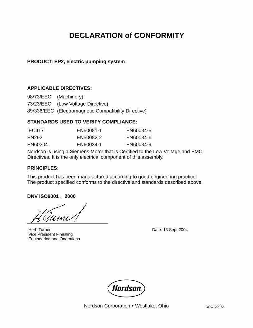
DECLARATION of CONFORMITY
PRODUCT: EP2, electric pumping system
APPLICABLE DIRECTIVES:
98/73/EEC (Machinery)73/23/EEC (Low Voltage Directive)89/336/EEC (Electromagnetic Compatibility Directive)
STANDARDS USED TO VERIFY COMPLIANCE:
IEC417 EN50081-1 EN60034-5EN292 EN50082-2 EN60034-6EN60204 EN60034-1 EN60034-9Nordson is using a Siemens Motor that is Certified to the Low Voltage and EMCDirectives. It is the only electrical component of this assembly.
PRINCIPLES:
This product has been manufactured according to good engineering practice.The product specified conforms to the directive and standards described above.
DNV ISO9001 : 2000
Date: 13 Sept 2004Herb TurnerVice President FinishingEngineering and Operations
Nordson Corporation � Westlake, Ohio DOC12007A