1030650 Exhibit A Scope of Work - Minnesota Department of ... · MnDOT Contract No. 1030650 I-35W...
24
MnDOT Contract No. 1030650 I-35W Stormwater Storage Facility Design Exhibit A- Scope of Work and Deliverables - 1 - 1.0 PROJECT OVERVIEW The project is located in Hennepin County, Minnesota, within the City of Minneapolis. The State is planning to design and construct a deep underground stormwater storage facility (SSF) adjacent to northbound Interstate 35W (I-35W) in the east embankment between 39th Street (St.) and 42nd St. in Minneapolis. I-35W near 42nd St. is a low point in the highway grade and is subject to flooding under certain precipitation events. Based on the TH 35W Stormwater Storage Facility Proof of Concept Report, October 2017, the SSF is expected to hold a minimum of 14 acre-feet of water below weir elevation of 814 feet (ft.). Work under this Contract includes aiding the Construction Manager General Contractor (CMGC) in concept selection and final design services and preparation of certified construction plans for the layout shown in Concept 1 including the SSF facility, weir, outlet pipes, lift station, and access shaft. In March 2016, the State evaluated the hydraulic feasibility of shallow storage options along southbound I-35W and in June 2016, the State resumed hydraulic discussions for deep storage options along northbound I-35W. In July 2016, the State began a deep storage geotechnical investigation to obtain relevant geological and groundwater information for this area. The east side of I-35W was selected in an attempt to stage the construction of this project with the current project on I-35W State Project (SP) 2782-327. Four SSF design concepts have been developed, all of which include a weir structure on the east shoulder of I-35W that diverts high flow stormwater events to the large underground structures during flooding events. The design concepts include three gravity draining options that connect to the existing stormwater tunnel drop shaft located at 39th St. and one non- gravity draining option that requires the stormwater to be pumped back to the surface and into an existing 78 inch diameter shallow pipe. The Trunk Highway (TH) 35W Stormwater Storage Facility Proof of Concept Report (October 2017) is available electronically for review. The report includes evidence and supporting data on design concepts that may be feasible for construction. It also includes summary information for project requirements, minimum performance requirements, special project considerations, pre-construction permitting, preliminary geotechnical information, preliminary construction/performance requirements, subsurface considerations and proof of concept information for the three vertical SSF options currently being considered. The addendum to the report includes the information on a fourth option, the linear tunnel. In October/November 2017, the State held a Cost Risk Assessment & Value Engineering (CRAVE) Study for this project. The primary objectives of this study were to verify or improve upon the various design concepts for the I-35W SSF project, evaluate the constructability for the concept, identify high risk areas for delivering the project, improve the value though innovations and perform a cost risk assessment of the design concepts. Several small modifications were thought to potentially work with the initial design concepts to improve the probability of meeting the project goals. A revised shallow storage option was also recommended, which created additional risks to the project and the local neighborhood. Following the CRAVE Study, the State eliminated the linear tunnel and revised shallow storage options from consideration. The following three design concepts, adapted from Table 6-1 of the Proof of Concept Report, are currently under consideration by State: DRAFT
Transcript of 1030650 Exhibit A Scope of Work - Minnesota Department of ... · MnDOT Contract No. 1030650 I-35W...
MnDOT Contract No. 1030650 I-35W Stormwater Storage Facility Design
Exhibit A- Scope of Work and Deliverables
- 1 -
1.0 PROJECT OVERVIEW The project is located in Hennepin County, Minnesota, within the City of Minneapolis. The State is planning to design and construct a deep underground stormwater storage facility (SSF) adjacent to northbound Interstate 35W (I-35W) in the east embankment between 39th Street (St.) and 42nd St. in Minneapolis. I-35W near 42nd St. is a low point in the highway grade and is subject to flooding under certain precipitation events. Based on the TH 35W Stormwater Storage Facility Proof of Concept Report, October 2017, the SSF is expected to hold a minimum of 14 acre-feet of water below weir elevation of 814 feet (ft.). Work under this Contract includes aiding the Construction Manager General Contractor (CMGC) in concept selection and final design services and preparation of certified construction plans for the layout shown in Concept 1 including the SSF facility, weir, outlet pipes, lift station, and access shaft. In March 2016, the State evaluated the hydraulic feasibility of shallow storage options along southbound I-35W and in June 2016, the State resumed hydraulic discussions for deep storage options along northbound I-35W. In July 2016, the State began a deep storage geotechnical investigation to obtain relevant geological and groundwater information for this area. The east side of I-35W was selected in an attempt to stage the construction of this project with the current project on I-35W State Project (SP) 2782-327. Four SSF design concepts have been developed, all of which include a weir structure on the east shoulder of I-35W that diverts high flow stormwater events to the large underground structures during flooding events. The design concepts include three gravity draining options that connect to the existing stormwater tunnel drop shaft located at 39th St. and one non-gravity draining option that requires the stormwater to be pumped back to the surface and into an existing 78 inch diameter shallow pipe. The Trunk Highway (TH) 35W Stormwater Storage Facility Proof of Concept Report (October 2017) is available electronically for review. The report includes evidence and supporting data on design concepts that may be feasible for construction. It also includes summary information for project requirements, minimum performance requirements, special project considerations, pre-construction permitting, preliminary geotechnical information, preliminary construction/performance requirements, subsurface considerations and proof of concept information for the three vertical SSF options currently being considered. The addendum to the report includes the information on a fourth option, the linear tunnel. In October/November 2017, the State held a Cost Risk Assessment & Value Engineering (CRAVE) Study for this project. The primary objectives of this study were to verify or improve upon the various design concepts for the I-35W SSF project, evaluate the constructability for the concept, identify high risk areas for delivering the project, improve the value though innovations and perform a cost risk assessment of the design concepts. Several small modifications were thought to potentially work with the initial design concepts to improve the probability of meeting the project goals. A revised shallow storage option was also recommended, which created additional risks to the project and the local neighborhood. Following the CRAVE Study, the State eliminated the linear tunnel and revised shallow storage options from consideration. The following three design concepts, adapted from Table 6-1 of the Proof of Concept Report, are currently under consideration by State:
DRAFT

MnDOT Contract No. 1030650 I-35W Stormwater Storage Facility Design
Exhibit A- Scope of Work and Deliverables
- 2 -
PARAMETER SSF CONCEPT 1 SSF CONCEPT 2 SSF CONCEPT 3 Operational Details Requires pump station Gravity-draining, drains
to State stormwater tunnel
Gravity-draining, drains to State stormwater tunnel
Weir Outlet Pipe 10 ft. in diameter, 45 ft. in length, 21 ft. deep, located in glacial till
10 ft. in diameter, 45 ft. in length, 21 ft. deep, located in glacial till
10 ft. in diameter, 1130 ft. in length, 27 ft. deep, located in glacial till
Storage Structure 14 acre-feet storage, Between 42nd and 41st St., (6)-45 ft. diameter cells, 84 ft. deep, Located in glacial till, Requires 30 ft. jet-grouting groundwater plug
14 acre-feet storage, Between 42nd and 41st St., (6)-45 ft. diameter cells, 84 ft. deep, Located in glacial till, Requires 30 ft. jet-grouting groundwater plug
14 acre-feet storage, Between 40th and 39th St., (10)-45 ft. diameter cells, 66 ft. deep, Extends through glacial till zone and founded in Platteville Limestone, Requires 10 ft. permeation grouting groundwater plug
Storage Structure Outlet Pipe
Not included Size and material determined during final design, 1490 ft. in length, 89 ft. deep, Extends through glacial till and St. Peter Sandstone
Size and material determined during final design, 270 ft. in length, 67-95 ft. deep, Extends through glacial till and St. Peter Sandstone
Access Shaft Not included 20 ft. in diameter; 94 ft. deep; Extends through glacial till, Platteville Limestone, and Glenwood Shale; Founded in St. Peter Sandstone
20 ft. in diameter; 94 ft. deep; Extends through glacial till, Platteville Limestone, and Glenwood Shale; Founded in St. Peter Sandstone
The State has scheduled the construction of the deep SSF under State Project (S.P.) No. 2782-347. The project is currently in the preliminary design phase. Additional geotechnical investigation, optimization of the construction technique and detailed design of the stormwater storage facility will need to be determined with the final design. The final scope of work for all repair items will be determined in final design in coordination between the State, State’s Contractor, and the CMGC Contractor. The preliminary scope of work, which is subject to change, is as follows:
Weir structure design complete and connection pipes to be installed under the I-35W Downtown to Crosstown Project, S.P. 2782-327;
DRAFT

MnDOT Contract No. 1030650 I-35W Stormwater Storage Facility Design
Exhibit A- Scope of Work and Deliverables
- 3 -
Secant/diaphragm structural walls and bottom groundwater plug and floor;
Drainage pipe connections that may include tunneling/microtunneling;
Temporary/permanent shoring;
Dewatering;
Mass excavation;
Back-flow preventer (if gravity drained);
Storage facility covers and access hatches;
Permanent instrumentation and monitoring of storage facility water levels and deformation including connection to Regional Traffic Management Center (RTMC) system;
Pumping system (if not gravity drained);
Other minor work around the project area. The project technical requirements must:
Provide a minimum of 14 acre-feet of underground storage below a weir elevation of 814 ft.
Include a weir structure connection to the storage facility that will provide a minimum discharge capacity of 590 cubic feet per second (cfs) with a headwater elevation of 812 ft. when there is 4.7 acre-feet of water in the storage facility.
Provide a 72-hour drawdown duration either gravity or pump drained requirement was assumed in concept development.
State has selected the CMGC procurement method, so that the Department can obtain construction and technical expertise from a Contractor during the pre-construction phase, with a particular focus on constructability, access, staging and the associated risks, costs and schedules for options under consideration. Reference and background materials for this project are available at the following project file transfer protocol (ftp) site: ftp://ftp2.dot.state.mn.us/pub/outbound/MetroWatersEdge/SP2782-347%2035W%20Stormwater%20Storage%20Facility/ Additional information regarding State’s CMGC process can be found on State’s CMGC Website: http://www.dot.state.mn.us/const/tools/const-manager-general-contractor.html Responders are advised that reference materials are updated regularly, and Responders are responsible for checking the websites for new or updated materials. Adjoining Project Description The I-35W Downtown to Crosstown project (S.P. 2782-327) provides for the reconstruction of I-35W between 42nd St. and I-94 in Minneapolis. S.P. 2782-327 is currently in the construction phase and is scheduled to be complete by the Fall of 2021. Ames-Lunda-Shafer (ALS), a joint venture, is the prime contractor. There are five construction stages anticipated for S.P. 2782-327. The last two stages (four and five), are anticipated to occur concurrently with and adjacent to, the SSF construction. The project website for S.P. 2782-327 contains more information about the project, including the construction staging: http://www.dot.state.mn.us/35w94/. In addition, the contract and staging plans for S.P. 2782-327 are available on the SSF ftp site: ftp://ftp2.dot.state.mn.us/pub/outbound/MetroWatersEdge/SP2782-347%2035W%20Stormwater%20Storage%20Facility/.
DRAFT
MnDOT Contract No. 1030650 I-35W Stormwater Storage Facility Design
Exhibit A- Scope of Work and Deliverables
- 4 -
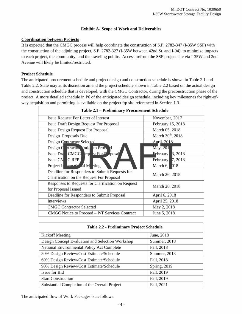
Coordination between Projects It is expected that the CMGC process will help coordinate the construction of S.P. 2782-347 (I-35W SSF) with the construction of the adjoining project, S.P. 2782-327 (I-35W between 42nd St. and I-94), to minimize impacts to each project, the community, and the traveling public. Access to/from the SSF project site via I-35W and 2nd Avenue will likely be limited/restricted. Project Schedule The anticipated procurement schedule and project design and construction schedule is shown in Table 2.1 and Table 2.2. State may at its discretion amend the project schedule shown in Table 2.2 based on the actual design and construction schedule that is developed, with the CMGC Contractor, during the preconstruction phase of the project. A more detailed schedule in P6 of the anticipated design schedule, including key milestones for right-of-way acquisition and permitting is available on the project ftp site referenced in Section 1.3.
Table 2.1 – Preliminary Procurement Schedule
Issue Request For Letter of Interest November, 2017 Issue Draft Design Request For Proposal February 15, 2018 Issue Design Request For Proposal March 05, 2018 Design Proposals Due March 30th, 2018 Design Contractor Selected April, 2018 Design Contractor Notice to Proceed May, 2018 Issue Draft CMGC Request For Proposal February 13, 2018 Issue CMGC RFP February 27, 2018 Project Informational Meeting March 6, 2018 Deadline for Responders to Submit Requests for Clarification on the Request For Proposal
March 26, 2018
Responses to Requests for Clarification on Request for Proposal Issued
March 28, 2018
Deadline for Responders to Submit Proposal April 6, 2018 Interviews April 25, 2018 CMGC Contractor Selected May 2, 2018
CMGC Notice to Proceed – P/T Services Contract June 5, 2018
Table 2.2 - Preliminary Project Schedule
Kickoff Meeting June, 2018
Design Concept Evaluation and Selection Workshop Summer, 2018
National Environmental Policy Act Complete Fall, 2018
30% Design Review/Cost Estimate/Schedule Summer, 2018
60% Design Review/Cost Estimate/Schedule Fall, 2018
90% Design Review/Cost Estimate/Schedule Spring, 2019
Issue for Bid Fall, 2019
Start Construction Fall, 2019
Substantial Completion of the Overall Project Fall, 2021
The anticipated flow of Work Packages is as follows:
DRAFT
MnDOT Contract No. 1030650 I-35W Stormwater Storage Facility Design
Exhibit A- Scope of Work and Deliverables
- 5 -
Work Package
30% Plan (draft design with estimated quantities) o Present submittal at Opinion of Probable Construction Cost (OPCC) workshop (one week after
submitting plans to State) o CMGC Interim Pricing (OPCC) Milestone (two weeks after workshop)
60% SSF – (with final design, updated details and quantities, and Draft Special Provisions) o Present submittal at OPCC workshop (one week after submitting plans to State) o CMGC Interim Pricing (OPCC) Milestone (two weeks after workshop)
90% SSF – (with fully checked design, details, quantities and Special Provisions) o Present submittal at OPCC workshop (one week after submitting plans to State) o CMGC Interim Pricing (OPCC) Milestone (two weeks after workshop)
Final SSF – (with completed peer review) o CMGC Issue for Bid (IFB) Plan Package
Based on State policy, Contractor will provide continuous coordination of design and plan review with Peer Reviewers, including resolution of review comments at 30%, 60% and 90% submittals for the SSF. Similar coordination is required with the CMGC. Contractor will cooperate with Peer Reviewers for Geotechnical and Hydraulic Design as part of the project team and contracted through State. Coordination efforts will be continuous throughout all design phases of the project and discussed in sections 2.4 and 2.5.
All work on this project will be performed in English units, and the plans, specifications, estimates, reports, etc. produced will be shown in English units. Metric units for the secant/diaphragm walls are to be shown in parenthesis. Final submittals of plans and specifications will be made in both reproducible hard copy originals and electronic files. 2.0 PROJECT MANAGEMENT 2.1 Contract Administration and Schedule Management
2.1.1 Contract Administration (Project Management 1010) The project will be administered and managed by the State. All other consultants and contractors working on the project report directly to the State. The State Project Manager will be the point of contact and primary State position. The State Project Manager will guide design decisions, while overseeing the collaborative process among the Project Team. State will provide a Project Manager to give direction to Contractor’s activities. It will be the responsibility of the State Project Manager to receive the work produced by Contractor, review the work for compliance with contract requirements, and to recommend payment for such work. The State’s Project Manager will provide a ProjectWise login with read only access where the Contractor will place electronic copies of all submittals. This process will be used to submit and receive project information throughout design.
Contractor’s Project Manager will conduct the administration of the project, which will include communication with the State on, invoicing, supplemental agreements, cost and schedule updates,
DRAFT

MnDOT Contract No. 1030650 I-35W Stormwater Storage Facility Design
Exhibit A- Scope of Work and Deliverables
- 6 -
billing preparation, and other non-technical work. Contractor will also create an electronic project directory for project file sharing. Project directory standards and file naming standards are available upon request to the Bridge Office Project Manager.
No changes in Contractor project management or lead design personnel will be made without prior written consent of the State Project Manager. State will notify Contractor immediately, if there are changes to State’s project management or lead design personnel.
2.1.2 Schedule Management (Project Management 1010)
State anticipates that the CMGC will provide a Critical Path Method (CPM) schedule for the construction of the project. Contractor’s task will be to work closely with the State Project Manager to coordinate the design schedule with the construction schedule in order to meet the proposed project completion date. Develop and maintain a P6 design schedule within the State System with the detail necessary to describe the design scope of services and highlight the deliverable dates at the various levels of design and CMGC coordination. Contractor assume three – two-hour meetings to develop the initial schedule with an update meeting scheduled every two weeks for 1.5 hours each. Schedule milestone deliverable dates for (30%, 60%, 90% and project turn in) will be agreed upon throughout the schedule development. The schedule development process will take place after the concept selection workshop.
2.2 Co-Location and Project Meetings 2.2.1 Co-Location and Design Concept Workshop (Project Management 1010)
Co-location is not required or anticipated for this project. However, there will be key design milestones (30%, 60%, and 90% design) when the Contractor’s key personnel will be expected to attend multi-day (one-two days) workshops with the project team. 2.2.2 Design Concept Selection Workshop (Value Engineering 1068) The Contractor will participate in a Design Concept Selection Workshop and a risk assessment with the project team. Provide analysis and support during concept selection to the construction contractor is expected. These workshops are expected to take place at State’s Metro Waters Edge location or another State facility in the Twin Cities metropolitan area. Evaluation could include benefit/cost analysis and investigation activities. This is anticipated to be a two-three day workshop.
2.2.3 Design Team Kick-Off Meeting (Project Management 1010)
Contractor will schedule a design kick-off meeting to establish communication protocol for the design, discuss known project issues, and review the project schedule. Contractor will receive available project information from State, including the most up-to-date preliminary design information. At the kick-off meeting Contractor will provide its Quality Management Plan (QMP) to State. Contractor will also attend half day formal partnering meeting. Contractor will also attend one-four hour partnering meeting. Note: Contractor will submit its list of meeting attendees to State’s Project Manager five days prior to the meeting.
2.2.4 Project Design Team (PDT) Meetings (Project Management 1010) State will establish a Project Design Team, which will be led by Contractor. Other participants will include:
DRAFT

MnDOT Contract No. 1030650 I-35W Stormwater Storage Facility Design
Exhibit A- Scope of Work and Deliverables
- 7 -
Project Manager: Nicole Peterson
Construction Project Manager: Tim Nelson
Hydraulics: Nick Olson
Structural Lead: Frank Jordan
Roadway Lead: Mike Kruse
Maintenance: Bill Augello
Geotechnical Peer Reviewer’s Project Manager (To Be Determined (TBD))
Hydraulic Peer Reviewer’s Project Manager (TBD)
Federal Highway Administration (FHWA): Ryan Hixson
CMGC TBD
State’s CMGC Program Manager: Kevin Hagness
Independent Cost Estimator TBD
Engineers Estimator TBD
State’s Estimating Representative: Nancy Sannes
Contractor will schedule weekly progress meetings for the PDT that will be held at Contractor’s local office with teleconferencing and video conferencing as needed. There will be 24 PDT meetings, with 14 meetings attended in-person at Contractor’s local office and 10 meetings attended via teleconference. Contractor will coordinate meetings and agenda items with other project stakeholders as necessary. Note: For PDT meetings, Contractor’s Project Manager, Lead Geotechnical Engineer, and Lead Water Resources Engineer will be in attendance. Subcontractors will attend PDT meetings on an as-needed basis, upon approval of the Project Manager. Assume two-hour meeting durations.
Immediately following the progress meetings, Contractor will meet with the State Project Manager and Peer Reviewer to discuss design-specific issues and peer review comments on deliverables that require resolution. Contractor will record and submit meeting minutes to the Project Manager within three business days after each meeting. (Assume two-hour meeting durations). Attendance will be 14 meetings in-person and 10 teleconference meetings, as stated in the previous paragraph.
2.2.5 Comprehensive Project Team Kick-off Meeting (Project Management 1010)
This meeting is intended to be the kick-off for the overall project team when the following parties are under contract: Contractor, Peer Reviewer, ICE and the CMGC. State or State’s General Engineering Consultant (GEC) will lead this meeting. The anticipated meeting date is mid-to-late Spring 2018. The goal of the meeting will be to review project information submitted to date, review the CMGC process, schedule, and to review an outline for project risk assessment procedures. State anticipates that CMGC process refinements will occur, as a result of this meeting.
2.2.6 Additional Project Meetings (as necessary) (Project Management 1010)
If weekly PDT Peer Reviewer via teleconference meetings are not held, Contractor’s Project Manager and Lead Water Resources Engineer will meet with the Project Manager and provide updates on progress of design activities. These teleconferences are two-hour teleconferences.
2.2.7 Public Outreach Activities (Public Outreach 054) The Contractor’s Project Manager will attend up to three public meetings.
DRAFT

MnDOT Contract No. 1030650 I-35W Stormwater Storage Facility Design
Exhibit A- Scope of Work and Deliverables
- 8 -
2.2.8 Supplying Information to Third Parties (Project Management 1010) Upon request from State’s Project Manager, Contractor will furnish project information, including plan sheets, electronic data files (description of content), and design information to third parties within five business days. Information requests received directly by Contractor will be routed through and approved by the Project Manager. When appropriate, this information may be furnished via ftp site, or disseminated by either paper or electronic format. Information may be supplied to only one recipient of an interested party (i.e. a property owner, an owner’s attorney, etc.). If necessary, Contractor to attend meetings with third parties, assume eight meetings.
2.3 CMGC Coordination and Risk Management (Project Management 1010) Contractor will work with the CMGC to improve the project quality and reduce project costs. This will include meeting with the CMGC to review designs at all stages, participating in Risk Workshops and contributing to the Project Risk Register at 30%, 60%, and 90% design stages, inviting the CMGC to participate in meetings with impacted third parties, and providing information to the CMGC to price the project and/or design alternatives under consideration. Each of these risk workshops are anticipated to be three days. The Contractor’s Project Manager will also attend a cost reconciliation meeting at 30%, 60% and 90% design stages. These are anticipated to be two days. 2.4 Quality Management Plan (QMP) and Quality Assurance/Quality Control (QA/QC) Procedures
(Project Management 1010) Contractor will develop a Quality Management Program/Plan that specifies how Contractor will perform QA and QC activities throughout the duration of the project to ensure delivery of a quality product in a timely manner that conforms to established contract requirements. Contractor will prepare the QMP and distribute it to all project team members, including subcontractors. Components of the QMP will include the following:
A List of Requirements
Process to integrate Peer Reviewer, CMGC, and State input
Technical Document Review Process
Checking Procedures
Quality Control Verification
Definitions
Contractor will ensure that the following Quality Control procedures are performed:
Design and Plan Sheet Check Contractor is responsible for the completeness and accuracy of the work. Final design calculations and plan sheets will be independently checked and reconciled prior to submittal. Review comments from State, CMGC, and Peer Reviewer on various plan submittals, do not relieve Contractor of its liability for an inaccurate or incomplete bridge plan. At the 60% and 90% submittals, Contractor will submit a memo—certified by the Lead QC Checker—that confirms that all aspects of the independent check have been performed in accordance with the QMP.
Quantity Check Final quantities shown in the plans will be the reconciliation of two independently made sets of calculations. Each set of calculations will be included with Contractor’s submittals and deliverables.
DRAFT

MnDOT Contract No. 1030650 I-35W Stormwater Storage Facility Design
Exhibit A- Scope of Work and Deliverables
- 9 -
Computer Programs All computer programs and/or spreadsheets utilized by Contractor will be verified by Contractor through its in-house QA Program. Input and output forms with the specific title of the program/spreadsheet will be included in Contractor’s design and quantity calculations.
Quality Assurance Verification Contractor’s Project Manager or QA Manager will review the entire plan design and production process to assure the completeness and adequacy of their work, and that it is in conformance with the Contractor’s QA procedures.
Independent Check, Peer Review, and Oversight Contractor Comment Resolution At the 30%, 60%, and 90% submittals, Contractor’s independent checker/team, Peer reviewer, will submit comment logs, which document comments, Contractor’s responses, and the status of final disposition. Contractor is responsible for resolution of comments from the independent checker/team, Peer Reviewer, and the CMGC, and resolution of red-lined revisions from State.
A complete independent design and analysis check is required for the Geotechnical and Hydraulic SSF design (Peer Reviewers). The personnel performing this check will be completely independent from the main design team responsible for plan production and will be procured by State.
2.5 Peer Review Coordination (Project Management 1010) State has determined this project to be a major SSF structure; therefore, a design review with independent design computations will be made by a Peer Reviewer. Contractor will cooperate with Independent Geostructural and Hydraulic Designers as part of the project team and contracted through State. Coordination efforts will be continuous throughout all design phases of the project, and will be coordinated through project meetings and conference calls to be scheduled weekly after each PDT meeting.
Contractor will coordinate formal reviews for concurrence with Peer Reviewer’s at the following stages of design:
30% Plan (with estimated quantities)
60% Package
90% Package
Final resolution of 90% plan comments (for Issue for Bid Package)
Special provisions (at the 60% and 90% submittals)
The results of the reviews will determine that the design and plans comply with design standards and the established design criteria. The Project Manager will resolve any outstanding issues with Contractor and Peer Reviewer.
2.5.1 Peer Review Process
Contract deliverables that require peer reviews will follow these general guidelines:
Contractor will coordinate the reviews with Peer Reviewer, the CMGC, and the Project Manager.
Contractor will submit four copies (or sets) of each deliverable to State (two), Peer Reviewer (one), and the CMGC (one) in accordance with the contract deliverables schedule.
Peer Reviewer and the CMGC will return contract deliverables to Contractor with red-lined notations and corrections in accordance with the contract deliverables schedule.
DRAFT

MnDOT Contract No. 1030650 I-35W Stormwater Storage Facility Design
Exhibit A- Scope of Work and Deliverables
- 10 -
Contractor will arrange a meeting with Peer Reviewer, the CMGC and the State Project Manager to discuss corrections and provide plan interpretation. Any design related issues that arise during the peer reviews will be resolved during these meetings.
Contractor will either make the revisions suggested by Peer Reviewer and the CMGC or provide written justification to the State Project Manager to proceed without incorporating Peer Reviewer’s suggested revisions.
Upon resolution of any design related issues, Contractor will submit final deliverables to State, in accordance with the contract deliverables schedule.
3.0 GEOTECHNICAL
3.1 Geotechnical Site Characterization (Foundation Recommendation 1190) This task consists of conducting any necessary document review, data collection, field exploration and investigations, field sampling, field testing, laboratory testing, analysis, computational modeling, or other efforts in support of preparation of a Geotechnical Analysis and Design Report (GADR) for the SSF. Contractor to produce a Geotechnical Baseline Report that documents anticipated subsurface conditions, describes how those conditions will influence construction, describes how those conditions have influenced the design, identifies key risks and describes who is responsible for the risks for conditions within and beyond the baselines. This is intended to provide a fair basis for contracting and assist in avoiding and resolving disputes during construction. This may include providing predetermined prices for differing site conditions encountered during construction. 3.2 Preparation of Geotechnical Analysis and Design (Foundation Recommendation 1190) This task consists of evaluating data obtained from available sources and additional investigation efforts conducted as described in 4.1 (above). Work will include the design evaluation of temporary and permanent works, foundation elements, foundation protection elements, roadway and embankment slope support, and potentially necessary safety measures for construction rock excavation and blasting. 3.3 Design and Detailing of Geotechnical Aspects of Project Plans, Construction Details and Specifications (Foundation Recommendation 1190) This task consists of developing the necessary plans and specification language required to successfully incorporate needed elements of the GADR reports into the project design plans. This may include designs related to soil removal and replacement, soil reinforcement, rock reinforcement, use of light weight fills, design of driven or drilled elements, in soil, difficult geo-materials and rock, for foundations, spread footing detailing, constructability assessments and preparation of instrumentation and monitoring program plans.
3.4 Constructability Review of Geotechnical Project Features, Mitigation Plans and Mitigation Measures (Foundation Recommendation 1190) This task includes an assessment of the design plans for risk, reliability, constructability, cost, and ability to construct the project in the project timeline. Attention will be paid to the impact of design decisions by others that could be changed to favorably impact geotechnical outcomes. 3.5 State Deliverables State will provide the following deliverables:
Arrange for site access and coordination
DRAFT

MnDOT Contract No. 1030650 I-35W Stormwater Storage Facility Design
Exhibit A- Scope of Work and Deliverables
- 11 -
Survey the locations of the ground survey targets
3.6 Secant Pile / Diaphragm Wall Shafts – Storage Facility (Foundation Recommendation 1190) Minimum design requirements for the secant pile wall to provide temporary lateral load support, to provide a watertight cut-off wall to minimize groundwater drawdowns outside the secant pile wall, and to minimize impacts on adjacent structures and utilities are shown on the Contract Drawings and described herein. These criteria are intended to serve as minimum requirements, as well as a guide to the Contractor for design of the secant pile wall. The Contractor will apply more stringent design requirements, if actual field conditions dictate. Develop detailed design that takes into account design criteria, codes and standards, field conditions, and construction sequencing. All temporary loading conditions that may result from the builder’s excavation and/or construction procedures will be included in the design. Design storage facility reinforcement to accommodate temporary and permanent loads, including any loads in addition to those specified in the design criteria. Analyze reinforcement requirements for loading conditions that may occur during construction operations. The secant pile wall will be constructed to accommodate microtunneling equipment and any operation needed to install the proposed tunnel/pipe.
1. Show configuration and details of completed storage facility, and potential equipment and method
of construction, including the following:
a. Reinforcing steel, including provision for lifting, stiffening, splicing, and centralizing fabricated cages with respect to the pile.
b. Any additional measures for support. c. Invert base slab plug anchorage details. d. Details of plates, sleeves, pipes, and other embedded items, including grout pipes, and
requirements for instruments and utilities to be installed in or through the wall. e. Details of block out material and block out locations. f. Sequence of construction of the various secant piles forming the shaft walls. g. Methods of excavation through water, fill, and/or rock formation. h. Method of maintaining stability of excavated pile holes including details of temporary casing. i. Method of monitoring deviation from vertical of bored holes during excavation, and details of
proposed corrective measures to be implemented if necessary. j. Equipment and method of checking and proving the cleanliness of excavated hole bottoms and
soundness of foundation material, prior to concreting. k. Method of cleaning holes. l. Method of installing and securing steel reinforcing as used. m. Method of placing concrete. n. Measures and repair methods to protect the environment, public, and surrounding property from
hazards inherent in the operations, including leakage and spillage of harmful materials. o. Locations of truck cleaning stations and methods of ensuring that haul trucks are clean and that
no spillage of excavated material from haul trucks occurs on existing streets.
DRAFT

MnDOT Contract No. 1030650 I-35W Stormwater Storage Facility Design
Exhibit A- Scope of Work and Deliverables
- 12 -
p. Concrete mix design including strength at three days, seven days and 28- day ages. Trial mix test result is to indicate strength at three days age and slumps immediately after mixing.
q. Details of concrete placement including proposed operational procedures for tremie and pumping methods.
r. Two samples of proposed spacers (side and bottom) for maintaining reinforcing steel in position.
2. Design calculations for groundwater cut-off and storage facility base stability.
3.7 Grout Plug / Jet Grouting Design (Foundation Recommendation 1190)
1 Jet grout plug is used for storage facility bottom stability, design plug to withstand the full height of hydrostatic pressure at the bottom of the storage facility and maintain invert stability.
2 Concrete Working Slabs: Provide concrete invert slab that engages the secant pile wall and provides working surface during construction.
3 Design storage facility bottom plug to withstand the full height of hydrostatic pressure at the bottom of the storage facility and maintain invert stability.
3.8 Geotechnical / Structural Instrumentation and Groundwater Monitoring (Foundation Recommendation 1190) Purposes of the Geotechnical and Structural Instrumentation Program include but are not limited to providing:
a. Pre-construction baseline data for comparison with construction and post- construction data. b. Monitoring of movements of ground, groundwater level, and facilities during and after
construction, to determine whether they have been affected by construction activities. c. A forewarning of unforeseen conditions and trigger actions required when “Threshold Levels”
and/or “Limiting Levels” have been reached. d. Install instruments and verify their satisfactory operation. Collect baseline readings and confirm
these readings. e. Layout plans and details of installation of all instrumentation on the conceptual layout in Plans
and actual field verification of same. Include on the layout plan the appropriate instrument reference number.
4 FINAL DESIGN COORDINATION
4.1 Site Data State will provide current structure site data including final proposed roadway geometry and typical sections, topographic maps of the site, and other data on features affecting the SSF design such as rail lines, hydraulic structures, right-of-way, city streets and existing utilities. The Contractor will not be required to perform field survey work.
4.2 Visual Quality (Public Customer Involvement 054) Visual Quality for this project will be determined in collaboration with the City of Minneapolis, State Metro District staff, and other select stakeholders. State will lead the Visual Quality effort.
DRAFT

MnDOT Contract No. 1030650 I-35W Stormwater Storage Facility Design
Exhibit A- Scope of Work and Deliverables
- 13 -
4.3 Hydraulics (Hydraulics Design 1141) 4.3.1 Review existing work to date including: project design files, hydraulics report, and Proof of
Concept Report. 4.3.2 Prepare drainage MicroStation plans, special provisions, and statement of estimated
quantities for project letting following State’s sample plan, standards, and approved software. State’s XPSWMM model of the 35W tunnel system is to be used for verification of compliance with design criteria.
4.3.3 Project involves the drainage design of a underground stormwater storage facility (SSF) meeting the following hydrologic/hydraulic performance requirements: a. A minimum of 14 acre-feet of storage for a 6-year 24-hour storm event beneath an
elevation of 814 ft. b. A diversions weir into the structure that provides a minimum discharge capacity of 590
cfs to the SSF with a headwater elevation of 812 ft. when there is 4.7 acre-feet of water in the SSF. Weir plans provided meet the elevation and discharge capacity requirements.
4.3.4 Project Modeling will demonstrate that the peak elevations on I-35W at the low point near 42nd St. (Model: Deep_42nd_NL_WEL814.xp Node: 42ND) (Model: Deep_42nd_NL_WEL814.xp Node: 42ND) are at or below the elevations found in the provided model for design storms, up to and including the six-year, 24-hour design storm. If the proposed SSF design exceeds the elevations reported by the current model, a new flood frequency analysis, as outlined in the Hydraulics Report, will be performed to ensure that the project’s requirement (as set by the FHWA) meets or exceed a six-year 24-hour storm event.
4.3.5 Plans will include: temporary and permanent drainage, stormwater storage design, weir design, Water Resources Engineering notes, drainage tabulations and profiles (put on same sheet and show existing utilities in their correct horizontal and vertical location based on utility information provided by State’s design), permanent turf establishment/erosion control, stormwater pollution prevention plan (SWPPP), and estimated quantities. a. The drawdown time of the SSF will be determined during final design to optimize costs
and maintenance requirements, but no less than 72-hour duration. Plans will also include design of a lift station, and all associated components, to pump water back into 78” trunk line sewer via the weir diversion pipe. See Pump/Lift Station (for Contractor’s design cost estimate assumes.
4.3.6 Design temporary and permanent drainage systems by avoiding and minimizing conflicts with existing utilities to the extent practicable.
4.3.7 At the completion of the SSF, plans will need to indicate the removal of the bulkheads in the 78 inch diversion pipes to and from the weir structure (diversion pipes to be constructed with SP 2782-327), as well as the abandonment of the unused section of 78 inch trunk line sewer in the median.
4.3.8 Tabulate the in-place drainage system and identify on plan sheets. Quantify the associated removals and show on the removals sheets. The existing drainage system has been surveyed
DRAFT

MnDOT Contract No. 1030650 I-35W Stormwater Storage Facility Design
Exhibit A- Scope of Work and Deliverables
- 14 -
by State surveys. Changes to the existing storm system will occur during the construction time period with the I-35W Downtown to Crosstown Project (SP 2782-327).
4.3.9 Incorporate and respond to plan review comments at the 30%, 60% and 90% stages and after plan turn-in to Central Office.
4.3.10 Perform and attend project coordination meetings with State staff, CMGC, consultants and regulatory agency staff.
4.3.11 Develop a drainage area map showing the contributing drainage areas and runoff coefficients from the City of Minneapolis and State to the I-35W Tunnel. Determine a percent flow contribution from each owner. Map will be provided by 30%.
4.3.12 Assist with drainage questions and issues and provide design support during construction from start to completion (estimated completion Fall of 2021).
4.4 Pump/Lift Station (Hydraulics Design 1141) 4.4.1 Will provide professional preliminary engineering analysis and final design services for
concept 1, a permanent lift station consisting of (2) submersible pumps (one pump is backup), a stationary backup natural gas generator, piping, building heating, ventilation, and air conditioning (HVAC) and electrical, electrical controls, and associated equipment. The pumping system will be designed to pump stormwater from the proposed SSF invert to a weir structure located adjacent to the SSF. For the preliminary design analysis, the engineer will provide a technical memorandum that provides and compares the estimated cost of a pumping system that is sized to pump 14 acre-feet of stormwater from the SSF within 72 hours and a smaller system that is designed to pump 14 acre-feet in 96 hours or longer with either one or multiple pumps, whichever is more cost effective. This technical memorandum will include estimated costs for the submersible pump(s), stationary backup natural gas generator, piping, building (HVAC and electrical), electrical controls, and associated equipment for each option.
4.4.2 The Contractor will prepare final drawings and specifications for the selected lift station option described above. The pumps will be centrifugal, non-clog, solids handling, submersible, explosion proof wastewater type pumps capable of handling raw unscreened wastewater and passing a three-inch diameter solid sphere. The pumps will be variable speed with use of variable frequency drive. The pump casing will have a centerline discharge equipped with an automatic pipe coupling arrangement for ease of installation and piping alignment. The pumps will automatically connect to the discharge piping when lowered into position. The pumps will be easily removed with a portable hoist for inspection or service, requiring no bolts, nuts, or other fasteners to be removed for this purpose, and no need for personnel to enter the SSF.
4.4.3 The pumps will have an electrode probe mounted in the seal chamber that emits a signal to the control system when a seal rupture occurs in the pump. The probe will be connected via a submersible cable to the control panel to alarm a seal failure when liquid is sensed, including a signal to RTMC to notify the operator of a problem. The pump motor will have a temperature monitor that emits a signal to the control system when an over temperature condition occurs.
4.4.4 The lift station will be equipped with dual stainless steel guide rails to guide the pump into proper alignment with the discharge elbow. The guide rails will extend from the discharge elbow to the upper guide holder on the access door. Guide rails will be full length, single piece construction from the factory. Field welded guide rails will not be acceptable. All
DRAFT

MnDOT Contract No. 1030650 I-35W Stormwater Storage Facility Design
Exhibit A- Scope of Work and Deliverables
- 15 -
guide rail piping and bracing inside the wet well structures will be stainless steel. The guide rail diameter and guide rail bracing spacing will be as recommended by the pump manufacturer. Intermediate guide rail braces will be stainless steel. A 316 stainless steel cable holder will be provided to hold the cables. The pumps will be equipped with a 316 stainless steel lifting chain long enough and strong enough to raise the pump for removal and inspection.
4.4.5 The electrical control panel will be specified and designed to monitor the operation of the pumps and associated floats and pressure transducer and send remote signals trough the on-site fiber optic network to the State Traffic Management System. The electrical control panel will be housed in a NEMA 4X stainless steel control panel. Four (4) level float switches and pressure transducer will be wired to the control panel and installed on non-corrosive cable racks inside the SSF structure to monitor the water elevations.
4.4.6 The process piping will be ductile iron or stainless steel. The consult will design all pipe supports as needed to support the piping. All gate and butterfly valves will be American Water Works Association (AWWA) certified.
4.5 Roadway (Traffic Control Design 1254)
4.5.1 Evaluate impacts to existing and proposed (SP 2782-327 contract) infrastructure and address impacts. Possible impacts include but not limited to: utilities, pavement/curb and gutter, noisewalls, traffic barrier, etc.
4.5.2 Determine clear zone requirements for 60 mph design speed and avoid placing fixed objects within this zone, if possible. If placing fixed objects within clear zone, provide necessary barrier to shield these objects in accordance with State standards.
4.5.3 In consultation with maintenance staff, evaluate and design any required permanent maintenance access features such as a maintenance pull off adjacent to the interstate shoulder.
4.5.4 Review the final three-dimensional geometry of the associated roadways.
4.6 Utilities (Utility Coordination 1195) The Contractor will be responsible for all utility coordination in accordance with the “Utility Accommodation and Coordination Manual. This can be found at http://www.dot.state.mn.us/utility/projectdelivery.html
Contractor Deliverables a. Facilitate and conduct utility design meetings. b. Determine utility conflict and resolutions c. Request utility relocation plans (if necessary) d. Facilitate and conduct utility design change meeting (if needed) e. Prepare and send Utility Verification Letters f. Review utility relocation plans and schedule with utility owners g. Incorporate Utility information in plan and Construction documents h. Prepare Utility Certification
State Deliverable: Issue Notice and Orders.
4.7 Permits (Hydraulics Design 1141) Prepare all required permitting:
DRAFT

MnDOT Contract No. 1030650 I-35W Stormwater Storage Facility Design
Exhibit A- Scope of Work and Deliverables
- 16 -
1. Minnesota Pollution Control Agency – National Pollution Discharge Elimination System (NPDES) Contractor to supply the information for this permit to State and State will apply on-line for the permit.
2. Minnesota Department of Natural Resources(MnDNR) – if permanent appropriations permit is needed (lift station option)
3. Coordination with Mississippi Watershed Management Organization (MWMO) – State does not receive a permit from MWMO, but most meets all requirements of their rules standards. Coordination was initially done with the MWMO for the Downtown to Crosstown Project, however, that coordination was based on storage under I-35W. Now that the storage will be under the embankment, treatment may be needed for the impervious associated with the covers/hatches on the storage chambers. This needs to be addressed with the MWMO. The water quality volume provided for the Downtown to Crosstown project was 1.57 acre-feet and the required volume was 0.75 acre-feet, so approximately 0.82 acre-feet of volume may be available for this project. The Downtown to Crosstown project also exceeded the total suspended solids (TSS) removal goal by 412 pounds, so that is available as well.
4.8 Traffic Management Plan (TMP) (Traffic Control Design 1255) Contractor to prepare project TMP per standard State guidelines.
4.9 Materials Design Recommendation (MDR) (Project Design Plans 1250) Prepare a MDR for the maintenance access, Contractor to follow Chapter 8 of the MnDOT Pavement Design Manual. The manual, including an MDR template, can be found online at http://www.dot.state.mn.us/materials/pvmtdesign/manual.html. 4.10 Traffic Management System (TMS) (Traffic MGT SYS Plans 1256) A communications cabinet will be provided with adjacent I-35W/Lake St Project. Coordinate any tie-in of water/structural monitoring systems with RTMC. During design, if it is determined existing TMS infrastructure will be impacted, the Contractor would detail in the Plans, Specs and Estimate for the construction to replace the impacted infrastructure. Develop a protocol/contingency plan for how the RTMC staff should optimally use water elevation data from the weir structure to warn motorists of potential for water on roadway when the SSF capacity is exceeded. The protocol/contingency plan will include advance message boards to warn motorists of potential for water on the road and to divert traffic to minimize disruption and maintain emergency vehicle use. An alert will be provided to the RTMC when water begins flowing over the weir, when the water in the storage tank is 50% full, and when tank is 100% full:
4.11 Lighting Lighting design is not anticipated in the project limits. Identify any lighting impacts to coordinate with adjacent I-35W/Lake St. Project. Contractor to account for necessary damages to lighting, and if there is a need to salvage and reinstall existing project lighting (as allowable) or directed by State’s Project Manager.
5 FINAL STRUCTURAL DESIGN AND PLAN PREPARATION (ABUTMENT) Contractor will complete final structural design and plan preparation for SSF, including analysis and design of the SSF Components and foundations. At a minimum, this task includes:
DRAFT

MnDOT Contract No. 1030650 I-35W Stormwater Storage Facility Design
Exhibit A- Scope of Work and Deliverables
- 17 -
5.1 Develop Load Cases Develop AASHTO Load Resistance Factor Design (LRFD) and American Concrete Institute (ACI) 350 load cases and combinations. 5.2 SSF Component Design Design SSF components in accordance with applicable LRFD provisions and State Standards. Soils to be modeled interactively in three-dimension while modeling the grout plug and SSF components. 5.3 Aesthetic Element Design Provide structural engineering necessary for incorporation of aesthetic features. 5.4 Drainage and Utility Design and Detailing Incorporate details for accommodating utilities. Utility design loads will be included in the design criteria.
5.5 Constructability Analysis and Design Contractor will perform constructability studies of the structure and details at the 30%, 60% and 90% stages of plan development. The CMGC, Peer Reviewer, and State will provide constructability input; however, Contractor will remain responsible for the adequacy of all constructability studies. With the 30% Plan (Work Package 1), Contractor will submit a two to three-page optimal construction method evaluation to State. This submittal will include concurrence of the CMGC. Immediately following each plan submittal stage, Contractor’s schedule will accommodate a three-week comment resolution period to address CMGC and Peer Reviewer comments on constructability. Contractor will not proceed with elements of design that are subject to change based on CMGC and Peer Reviewer input until directed by the State Project Manager. 5.6 Construction Load and Analysis Analyze and design the SSF Components for anticipated construction loads after finalizing necessary construction phasing. Schematic drawings of the construction procedures and loads assumed during design will be included in the final SSF plans. 5.7 SSF Coordinate Geometry Calculate SSF geometry based on final roadway plan and profile. Provide all other coordinate geometry to construct the SSF. 5.8 Miscellaneous Design Provide design and detailing for miscellaneous SSF component elements, including, but not limited to, anti-graffiti coating, SSF access, etc. Contractor’s electrical design lead (or subconsultant) will provide engineering, plans, and specifications for any SSF controls and/or lighting systems. All electrical plan sheets will be certified by an electrical engineer registered in the State of Minnesota. 5.9 Shop Drawing Review of SSF Components
DRAFT

MnDOT Contract No. 1030650 I-35W Stormwater Storage Facility Design
Exhibit A- Scope of Work and Deliverables
- 18 -
State will receive, log and track all shop drawings related to this project. State will distribute three copies (or electronic PDF) of the shop drawings to Contractor for review, comment and distribution. Contractor will review shop drawings for general conformance with design concepts and intent of the construction contract documents including geometrics, welding and material. Work will consist of the following:
5.9.1 Annotated Shop Drawings
Contractor will return two annotated copies (or electronic PDF) of shop drawings to State for distribution. Shop drawings will be annotated as necessary and marked with one of the following actions to be addressed:
a) No exceptions taken b) Make corrections noted c) Revise and resubmit d) Rejected – see remarks
5.9.2 Responses to Requests for Information (RFIs)
State will receive RFIs for the project. State will distribute RFIs related to the SSF design to Contractor. Contractor will provide responses to RFIs to State if so directed by State under supplemental compensation to this contract. State and Contractor will negotiate supplemental compensation for this task at an appropriate time during the project.
6 DESIGN STANDARDS All designs will conform to applicable requirements of the following:
Type, size, and location plan provided by State;
Visual Quality Information;
MnDOT Computer Assisted Design & Drafting (CADD) Standards;
MnDOT Preliminary Subsurface Investigation and Foundation Evaluation.
Construction requirements of the current 2018 MnDOT Standard Specifications for Highway Construction and any supplements thereto on file in the Office of the Commissioner of Transportation will be incorporated into the plans. 7. PLAN CONTENT Plan content for SSF Components per MnDOT Metro Roadway Plan and Guidance for Special Drainage Structures.
7.1. Structures Plan Sheet Requirements 7.1.1. Title Sheet
Minimum items that will appear on the Title Sheet are a Plan View of the SSF showing adjacent roadways, structures, and features and an Engineering Certification Block for the Engineer of Record’s signature.
7.1.2. Index of Sheets and Schedule of Quantities
DRAFT

MnDOT Contract No. 1030650 I-35W Stormwater Storage Facility Design
Exhibit A- Scope of Work and Deliverables
- 19 -
This sheet will include a numerical listing of all plan sheets and Schedule of Pay Items and Quantities in tabular form. Multiple sheets may be required to avoid crowding of information.
7.1.4 Design Criteria/Construction Notes Sheet(s) 7.1.5 General Plan and Elevation Sheet(s) 7.1.6 SSF Control Point Layout Sheet(s) 7.1.7 Geotechnical Layout Sheet(s)
A Deep Foundation Element plan view will be detailed if the design calls for a Deep Foundation. Plan views to include Deep Foundation spacing and test Deep Foundation identification at each foundation. Deep Foundation Elements are to be tied into work line and working points. A Deep Foundation load table with applicable notes is included for each foundation. Including lateral earth pressures, slope stability information, Grout Plug, etc.
7.1.8 Architectural Detail Sheets 7.1.9 SSF Component Sheets
a. Excavation details and construction sequencing for each SSF Component b. Geometrics and Details for each SSF Component c. Reinforcement Details for each SSF Component d. Other Details as necessary
7.2 Final Plan Certification
The final plans for each Work Package will be certified by a professional engineer licensed under the laws of the State of Minnesota and as provided for under Minnesota Statute Section 326.12 and the Minnesota State Board of Architecture, Engineering, Land Surveying, Landscape Architecture, Geoscience, and Interior Design. All plan sheets will be certified.
7.3 CADD Files Electronic CADD files of the final certified bridge plan are included in the final deliverables for this Contract. All files will be submitted in MicroStation. Files will be assembled in accordance with the following conventions and procedures:
7.3.1 File Requirements:
a. Use the correct file naming convention for all files. b. For each plan set there will be only one file per file naming convention; therefore, merge/copy
plan sheets/details or files into one file. Multiple files may be provided if approved by State. c. All reference files that are part of the finished plan sheet will be merged into a master file.
Reference files are not allowed; therefore, detach all reference files after merging needed files and details.
d. Remove all elements that are not part of the final plan sheet; remove all elements that do not reside within the boundaries of the sheet border.
e. Sheet numbers are to be numeric. The exception is on revised plan sheets where an “R” follows the sheet number.
7.3.2 File Naming Convention
a. File name will be: “DR” + “SP number” + “_” + “file extension.dgn” (Example: DRXXXXXX_cp1.dgn).
DRAFT

MnDOT Contract No. 1030650 I-35W Stormwater Storage Facility Design
Exhibit A- Scope of Work and Deliverables
- 20 -
8.0 30% PLAN (Project Design Plans 1250) Contractor will provide project management services, including peer review coordination, for the development of the concept (30%) design and 30% Plan. The 30% Plan allows Peer Reviewer, State and the CMGC an early review of the final plan preparation for conformance with existing plans, aesthetic guidelines, and key design specifications. The intent of this review is to identify design discrepancies at an early stage and avoid major plan modifications resulting from future reviews. These partially completed plans will be used to share technical information for purposes of coordination and to build consensus with State and Peer Reviewer. At this stage, there will be a discussion of potential revisions to the design criteria, development and presentation of project details, and development of a draft list of pay items and an outline of the special provisions. The plans will be on 11" x 17", 20-lb white bond paper or approved equivalent. State, Peer Reviewer and the CMGC may meet with Contractor to return a copy of the 30% Plan containing its red-lined notations and corrections. State will authorize Contractor in writing to proceed with final design in conformance with the red-lined copy of the 30% Plan. If Contractor disagrees with Peer Reviewer or the CMGC’s notations and corrections, these differences will be resolved. Contractor may proceed to final design prior to the written authorization at its own risk.
8.1 Design Considerations The following items will be considered:
a. Contaminated soils b. Soil and Rock Stratigraphy and material properties c. Groundwater d. Construction means and methods e. Construction Safety f. Utilities (with potential for additional utilities identified during final design) g. Foundation type and SSF Component types h. Construction staging i. Soil-Structure interaction parameters
8.2 30% Plan Submittal
At a minimum the 30% Plan will consist of the following: a. General Plan and Elevation Sheet(s)
For this submittal the General Plan and Elevation sheet(s) need be completed only to the extent necessary to show general dimensions, elevations, cross section with proposed SSF option, architectural features, stage construction information and basic design data.
b. Draft pay item list c. Draft quantities d. SSF Layout Sheet(s)
For this submittal the SSF Layout sheet(s) will show reference lines, and proposed control point locations. It will also contain any sections, and notations needed to clarify the control point locations.
e. Architectural or Special Detail Sheet(s)
DRAFT
MnDOT Contract No. 1030650 I-35W Stormwater Storage Facility Design
Exhibit A- Scope of Work and Deliverables
- 21 -
Architectural or special detail sheet(s) showing any standardized shapes proposed to maximize repeatability of SSF Components and other special details that require early coordination between Contractor and State prior to final plan preparation.
f. SSF Survey Sheet(s) Survey sheets are to be included. For this submittal they are not required to be completed.
g. Any supporting design computations used to develop the aforementioned items.
8.3 30% Plan Peer Review Contractor will coordinate the peer review of the 30% Plan with Peer Reviewer and the CMGC. 8.4 Contractor deliverables:
a. 30% Plan four plan sets - State (2), Peer Reviewer (1) and the CMGC (1), including: b. Draft GADR c. Peer Reviewer and CMGC will return the 30% Plan to Contractor with red-lined notations and
revisions within two weeks of receipt from State Project Manager d. Incorporation of CMGC comments (as directed by State Project Manager) e. Final 30% Plan – two sets to State
9.0 60% PLAN (Project Design Plans 1250) Contractor will submit two sets of the 60% Plan, along with draft Special Provisions, draft quantities, two bound hard copies of draft design calculations, and electronic Portable Document Format (.pdf) files of the Plan, to State, Peer Reviewer and the CMGC. The plans will be on 11" x 17", 20-lb white bond paper or an approved equivalent. State will perform a cursory review to assess Contractor’s progress. Contractor may continue with final plan preparation during this review. Peer Reviewer and the CMGC will return a copy of the 60% Plan containing red-lined notations and corrections to Contractor. If Contractor disagrees with any suggested revisions, these differences will be resolved. If necessary, a meeting will be held with State, Contractor, Peer Reviewer and the CMGC to resolve issues. 9.1 60% Plan Peer Review
Contractor will coordinate the review of the 60% Plan and 60% Constructability Study with Peer Reviewer and the CMGC.
9.2 Contractor deliverables:
a. Draft 60% Plan (four plan sets) – State (2), Peer Reviewer (1) and CMGC (1) b. Electronic files of in-progress plan c. Final foundation recommendations and the geotechnical engineering review d. Draft Special Provisions e. Draft pay items and anticipated quantities f. Draft design calculations g. Electronic files (.pdf) of the plan h. Peer Reviewer and the CMGC will return the draft 60% Plan to Contractor with red-lined notations
and suggested revisions within four weeks of receipt from the Project Manager. 10.0 90% PLAN (Project Design Plans 1250)
DRAFT

MnDOT Contract No. 1030650 I-35W Stormwater Storage Facility Design
Exhibit A- Scope of Work and Deliverables
- 22 -
The 90% Plan submittal is to be considered 100 % complete by Contractor, ready for peer review. Plan will be ready for Contractor’s certification and approval by the State Hydraulics Engineer. The plan will contain corrections provided by previous plan submittals. The 90% Plan Submittal will contain the following:
Two plan sets on 11" x 17", 20-lb white bond paper or approved equivalent
One hard copy of bound and indexed design calculations
Bound and indexed quantity calculations, two independent sets – one hard copy each
One bound hard copy of Special Provisions
Contractor will submit the 90% Plan to State, Peer Reviewer and the CMGC. State, Peer Reviewer and the CMGC may meet with Contractor to return a copy of the 90% Plan with red-lined notations and corrections. Peer Reviewer and the CMGC will return the 90% Plan with red-lined notations and corrections to Contractor. If Contractor disagrees with any suggested revisions, these differences will be resolved. All corrections will be made prior to submittal of final deliverables. Contractor will make corrections and submit a Final Certified Plan to State.
10.1 90% Plan Peer Review Contractor will coordinate the peer review of the 90% Plan and 90% Constructability Study with the Peer Reviewer and the CMGC.
If State or Peer Reviewer determines that major plan revisions are necessary, Contractor will prepare and furnish a revised 90% plan. 10.2 Contractor deliverables:
a. 90% Plan (four plan sets) – State (2), Peer Reviewer (1) and the CMGC (1) b. Electronic copy of final design and quantity calculations c. Electronic copy of Special Provisions d. Electronic copy of the Plan (MicroStation) e. Peer Reviewer and the CMGC will return the 90% Plan to the Contractor with red-lined notations
and suggested revisions within three weeks to the Project Manager. f. Drainage area map. Drainage report, XP-SWMM model, documentation of coordination with the
MWMO, DNR (permanent Water Appropriations Permit, if needed) and MPCA (NPDES permit information).
g. Final GADR 11.0 POST-CONSTRUCTION OWNER’S MANUAL (Project Design Plans 1250) Upon written authorization from the State Project Manager, Contractor will provide an Owner’s Manual that provides inspection and maintenance guidance for the SSF and all of its’ components including but not limited to: the weir structure, SSF, pumps, float controls, electrical systems, lift station instrumentation, and piping. The following items will be included:
a. Long-term Maintenance Plan a. Develop long-term maintenance and operation plan: Including 30 year maintenance cost for each
option.
DRAFT

MnDOT Contract No. 1030650 I-35W Stormwater Storage Facility Design
Exhibit A- Scope of Work and Deliverables
- 23 -
b. Operations Plan: Standard Operating Procedure for each activity c. Safety: Safety Procedures for each activity, training needed, special equipment etc. d. Equipment, Personnel, and Access e. If non-permanent pump is used – (three) suggested vendors and suggested contract language will
be provided. b. Inspections plan
a. Identify inspection needs: Structural c. Develop the Maintenance, Operations and Inspection manual as the plan develops to allow input into the
design. a. State staff will review the plan at 30%, 60%, and 90%. b. Meet with State Maintenance and Inspection Staff at 30%, 60%, and 90%
d. Contractor Deliverables a. Operation and Maintenance Costs will only be determined for the selected SSF option. b. Four preliminary copies of operation and maintenance instructions will be submitted with shop
drawings for approval and will be resubmitted with corrections and additional requested information as needed.
c. Prepare and submit six final copies of a complete set of operation and maintenance instructions covering all equipment and systems provided. Operating instructions will be prepared specifically for each system or piece of equipment installed under this contract and will consider the specific equipment and controls included. All references, pictures and diagrams dealing with items not part of furnished equipment and systems will be deleted. Instructions will be complete for each separate system.
d. Include contact names, addresses, and telephone numbers of the manufacturer and manufacturer’s representative or supplier.
e. The list of information to be provided can be summarized as follows, but not by way of limitation: Outline, cross sections, and assembly drawings including all engineering data and wiring
diagrams for specific application. Assembly, installations, alignment, adjustment, and checking instructions. Test data and performance curves where applicable. Parts lists, and predicted life of parts subject to wear. Maintenance schedules and instructions. Operating instructions for start-up, normal operation, shutdown, and emergency
conditions. Detailed information on all controls. Include all limiting conditions. Guide to “troubleshooting”. A complete spare parts list for each piece of equipment and/or system.
12.0 SPECIAL PROVISIONS AND COST ESTIMATE (Project Design Plans 1250) Contractor will perform the following tasks:
12.1 Special Provisions
Develop and maintain a list of materials and procedures required for the project early and throughout the development process so items requiring special provisions are not overlooked when final special provisions are being prepared.
Develop and certify entire Division S Project Special Provisions and any other unique items not covered in the State’s Standard Specifications for Construction.
DRAFT

MnDOT Contract No. 1030650 I-35W Stormwater Storage Facility Design
Exhibit A- Scope of Work and Deliverables
- 24 -
12.2 Contractor deliverables: Draft special provisions for all Work Packages are due with the 60% plan submittals and Final Special Provisions for all Work Packages are due with the 90% plan submittals.
12.3 Cost Estimates
Cost Estimates will be prepared at the at 30%, 60% and 90% submittals are based on Plans, Special Provisions and Estimated Quantities provided by Contractor.
13.0 State Deliverables
a. Background Information b. Reference and Background material for this project are available at the below FTP site: c. ftp://ftp2.dot.state.mn.us/pub/outbound/MetroWatersEdge/SP2782-
347%2035W%20Stormwater%20Storage%20Facility/ d. Right of Way Acquisition e. Surveys f. Existing Utilities g. Environmental; Phase I and Phase II reports, Cultural Resource Update, Endangered Species
Review and Vegetation Review. h. Time and Traffic Provisions
It is Contractor’s responsibility to examine all materials provided by State for completeness and to notify State in a timely manner, if additional information is required. 14.0 POTENTIAL ADDITIONAL SERVICES The following potential additional services can be added to the scope of work, if so directed by State. For any services added, State and Contractor will negotiate additional scope and compensation to be included by amendment.
a. Additional cost estimating or design analysis prior to the concept selection workshop. b. Construction Contractor’s Engineer Services for Temporary Works. c. Potential for additional work packages. d. Analyze and design multiple preliminary concepts for various components of the SSF. This may
include coordination with the CMGC Contractor to provide estimates and price comparison. Examples may include but not be limited to pumps or gravity drains for varying drawdown times, innovative weir design and/or 30-year maintenance and operation costs.
e. Cost/Benefit comparison for the multiple design life cycles of the storage cells. f. Construction Engineering for the Construction Contractor. g. Onsite Construction Coordination and Construction Quality Assurance. h. Review of Construction Contractor’s RFI’s/NCR’s. i. Preparation of As-Built Drawings. j. Other as directed by State.
THE BALANCE OF THIS PAGE HAS BEEN INTENTIONALLY LEFT BLANK
DRAFT