
10.12 Sprue Bushing 12S Series - synventive.com · 10.12.1 Technical Data - Sprue Bushing 12S Sprue...
20
EN C P T A Master Language is English Hot Runner System Instruction Manual SVC-17-0001_EN-Rev03 RESTRICTED: Property of Synventive. - 506 - All rights reserved. Errors and omissions excepted For limited third party distribution based on need and intended use. © 2015 Synventive Molding Solutions Service and Maintenance / Sprue Bushing 12S Series 10.12 Sprue Bushing 12S Series NOTICE Always tighten the screws to the torque specified in the respective table in section 13. Hazard of Pressurized Air Pressurized air blow can result in hot plastic or foreign bodies entering the eyes, causing vision damage. Following work must be carried out by qualified and experienced persons. Use personal protective equipment: Face protection, hearing protection and gloves. Hazard of Material Damage Without consulting Synventive it is not permitted to do modifications to the hot runner system e.g. geometrical changes to the nozzle tip, except the part shape adjustment in the area of material allowance. 10.12.1 Technical Data - Sprue Bushing 12S Sprue Bushing 12S Doc005471.tif Flow Bore (J) Ø 12 mm Nozzle Length (L) 60 - 650 mm Nozzle Cut-out (D) Ø 35 mm Thermocouple Type J, Type K Nozzle Tips TFP, TTP, TTW
Transcript of 10.12 Sprue Bushing 12S Series - synventive.com · 10.12.1 Technical Data - Sprue Bushing 12S Sprue...
EN
C P
T A
Master Language is English Hot Runner System Instruction Manual SVC-17-0001_EN-Rev03RESTRICTED: Property of Synventive. - 506 - All rights reserved. Errors and omissions exceptedFor limited third party distribution based on need and intended use. © 2015 Synventive Molding Solutions
Service and Maintenance / Sprue Bushing 12S Series
10.12 Sprue Bushing 12S SeriesNOTICE
Always tighten the screws to the torque specified in the respective table in section 13.
Hazard of Pressurized AirPressurized air blow can result in hot plastic or foreign bodies entering the eyes, causing vision damage.Following work must be carried out by qualified and experienced persons.Use personal protective equipment: Face protection, hearing protection and gloves.
Hazard of Material DamageWithout consulting Synventive it is not permitted to do modifications to the hot runner system e.g. geometrical changes to the nozzle tip, except the part shape adjustment in the area of material allowance.
10.12.1 Technical Data - Sprue Bushing 12S
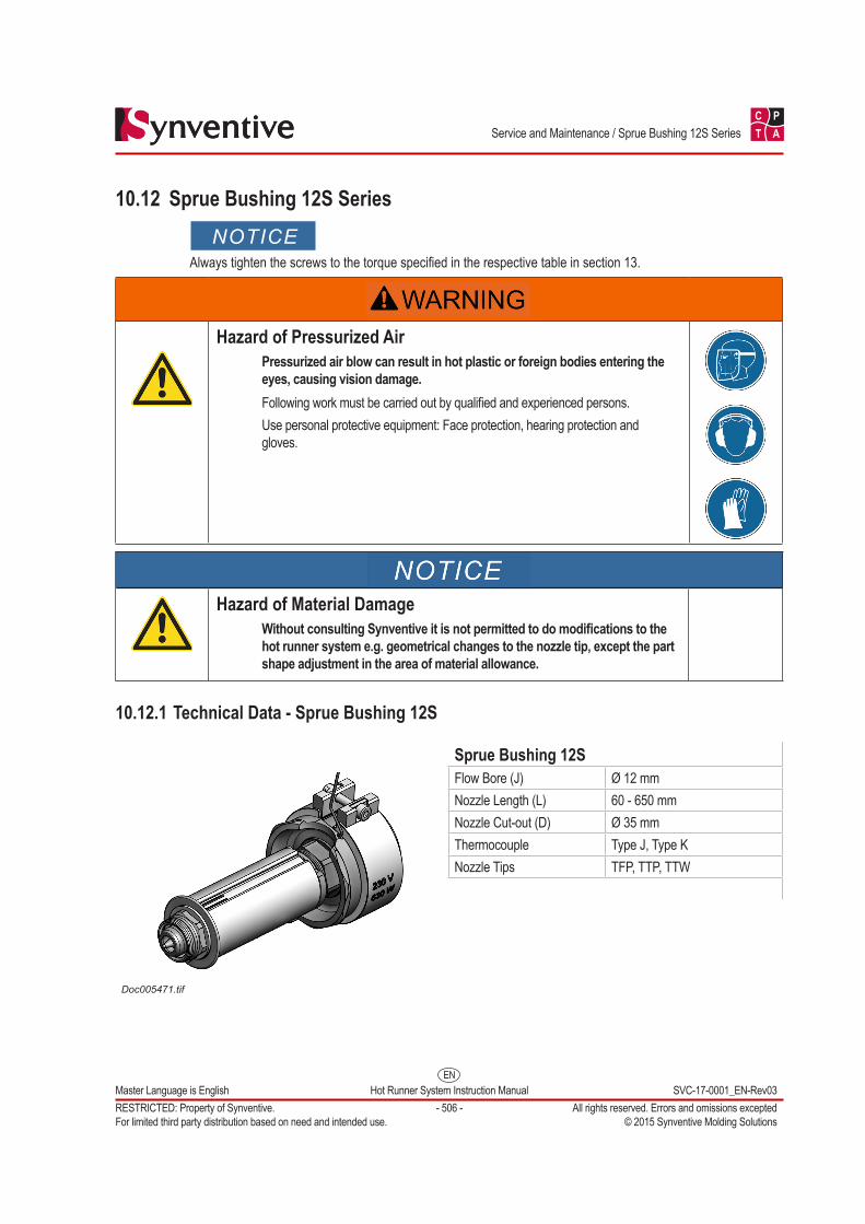
Sprue Bushing 12S
Doc005471.tif
Flow Bore (J) Ø 12 mmNozzle Length (L) 60 - 650 mmNozzle Cut-out (D) Ø 35 mmThermocouple Type J, Type KNozzle Tips TFP, TTP, TTW
EN
C P
T A
Master Language is English Hot Runner System Instruction Manual SVC-17-0001_EN-Rev03RESTRICTED: Property of Synventive. - 507 - All rights reserved. Errors and omissions exceptedFor limited third party distribution based on need and intended use. © 2015 Synventive Molding Solutions
Service and Maintenance / Sprue Bushing 12S Series
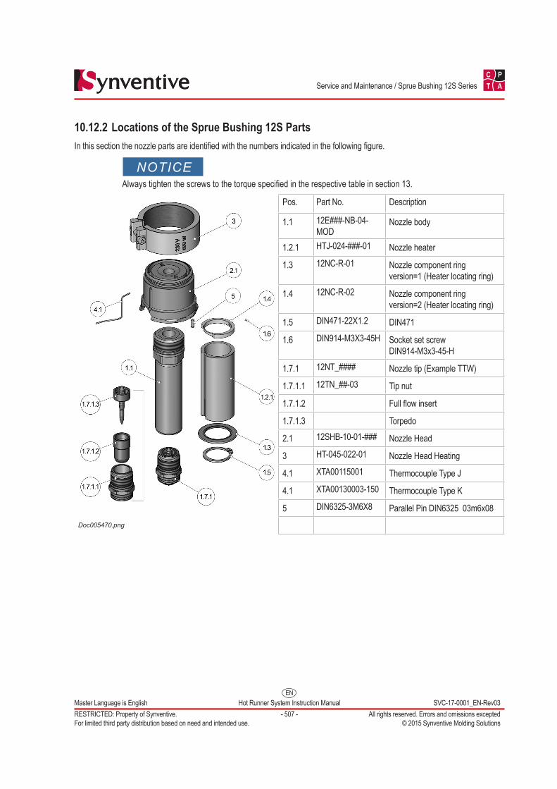
10.12.2 Locations of the Sprue Bushing 12S PartsIn this section the nozzle parts are identified with the numbers indicated in the following figure.
NOTICEAlways tighten the screws to the torque specified in the respective table in section 13.
Doc005470.png
Pos. Part No. Description
1.1 12E###-NB-04-MOD
Nozzle body
1.2.1 HTJ-024-###-01 Nozzle heater
1.3 12NC-R-01 Nozzle component ring version=1 (Heater locating ring)
1.4 12NC-R-02 Nozzle component ring version=2 (Heater locating ring)
1.5 DIN471-22X1.2 DIN471
1.6 DIN914-M3X3-45H Socket set screw DIN914-M3x3-45-H
1.7.1 12NT_#### Nozzle tip (Example TTW)
1.7.1.1 12TN_##-03 Tip nut
1.7.1.2 Full flow insert
1.7.1.3 Torpedo
2.1 12SHB-10-01-### Nozzle Head
3 HT-045-022-01 Nozzle Head Heating
4.1 XTA00115001 Thermocouple Type J
4.1 XTA00130003-150 Thermocouple Type K
5 DIN6325-3M6X8 Parallel Pin DIN6325 03m6x08
EN
C P
T A
Master Language is English Hot Runner System Instruction Manual SVC-17-0001_EN-Rev03RESTRICTED: Property of Synventive. - 508 - All rights reserved. Errors and omissions exceptedFor limited third party distribution based on need and intended use. © 2015 Synventive Molding Solutions
Service and Maintenance / Sprue Bushing 12S Series
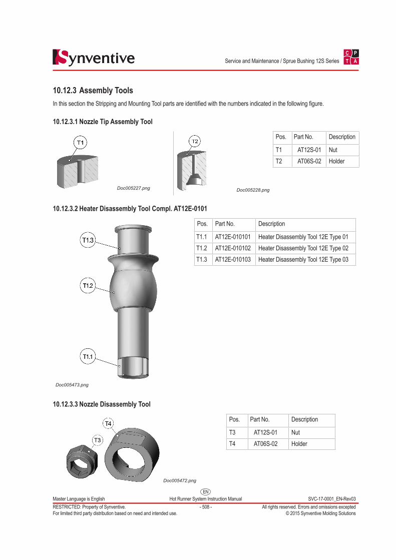
10.12.3 Assembly ToolsIn this section the Stripping and Mounting Tool parts are identified with the numbers indicated in the following figure.
10.12.3.1 Nozzle Tip Assembly Tool
Doc005227.png Doc005228.png
Pos. Part No. Description
T1 AT12S-01 NutT2 AT06S-02 Holder
10.12.3.2 Heater Disassembly Tool Compl. AT12E-0101
Doc005473.png
Pos. Part No. Description
T1.1 AT12E-010101 Heater Disassembly Tool 12E Type 01T1.2 AT12E-010102 Heater Disassembly Tool 12E Type 02T1.3 AT12E-010103 Heater Disassembly Tool 12E Type 03
10.12.3.3 Nozzle Disassembly Tool
Doc005472.png
Pos. Part No. Description
T3 AT12S-01 NutT4 AT06S-02 Holder
EN
C P
T A
Master Language is English Hot Runner System Instruction Manual SVC-17-0001_EN-Rev03RESTRICTED: Property of Synventive. - 509 - All rights reserved. Errors and omissions exceptedFor limited third party distribution based on need and intended use. © 2015 Synventive Molding Solutions
Service and Maintenance / Sprue Bushing 12S Series
10.12.4 Nozzle Thermocouple
10.12.4.1 Dismounting Nozzle Thermocouple
NOTICEFor dismounting of the thermocouple the nozzle heater must be dismantled from the nozzle.
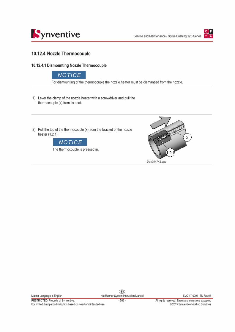
1) Lever the clamp of the nozzle heater with a screwdriver and pull the thermocouple (x) from its seat.
2) Pull the top of the thermocouple (x) from the bracket of the nozzle heater (1.2.1).
NOTICEThe thermocouple is pressed in.
Doc004742.png
EN
C P
T A
Master Language is English Hot Runner System Instruction Manual SVC-17-0001_EN-Rev03RESTRICTED: Property of Synventive. - 510 - All rights reserved. Errors and omissions exceptedFor limited third party distribution based on need and intended use. © 2015 Synventive Molding Solutions
Service and Maintenance / Sprue Bushing 12S Series
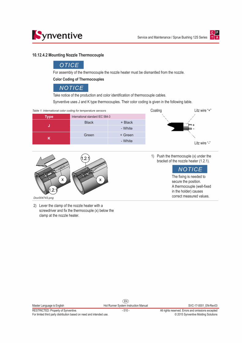
10.12.4.2 Mounting Nozzle Thermocouple
OTICEFor assembly of the thermocouple the nozzle heater must be dismantled from the nozzle.Color Coding of Thermocouples
NOTICETake notice of the production and color identification of thermocouple cables.Synventive uses J and K type thermocouples. Their color coding is given in the following table.
Table 1: International color coding for temperature sensors
Type International standard IEC 584-3
JBlack + Black
- White
KGreen + Green
- White
Coating Litz wire “+”
Litz wire “-”
Doc004743.png
1) Push the thermocouple (x) under the bracket of the nozzle heater (1.2.1).
NOTICEThe fixing is needed to secure the position. A thermocouple (well-fixed in the holder) causes correct measured values.
2) Lever the clamp of the nozzle heater with a screwdriver and fix the thermocouple (x) below the clamp at the nozzle heater.
EN
C P
T A
Master Language is English Hot Runner System Instruction Manual SVC-17-0001_EN-Rev03RESTRICTED: Property of Synventive. - 511 - All rights reserved. Errors and omissions exceptedFor limited third party distribution based on need and intended use. © 2015 Synventive Molding Solutions
Service and Maintenance / Sprue Bushing 12S Series
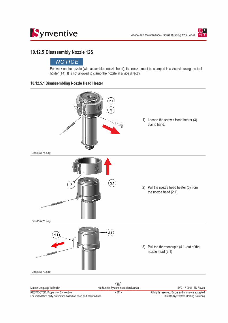
10.12.5 Disassembly Nozzle 12S
NOTICEFor work on the nozzle (with assembled nozzle head), the nozzle must be clamped in a vice via using the tool holder (T4). It is not allowed to clamp the nozzle in a vice directly.
10.12.5.1 Disassembling Nozzle Head Heater
Doc005475.png
1) Loosen the screws Head heater (3) clamp band.
Doc005476.png
2) Pull the nozzle head heater (3) from the nozzle head (2.1)
Doc005477.png
3) Pull the thermocouple (4.1) out of the nozzle head (2.1)
EN
C P
T A
Master Language is English Hot Runner System Instruction Manual SVC-17-0001_EN-Rev03RESTRICTED: Property of Synventive. - 512 - All rights reserved. Errors and omissions exceptedFor limited third party distribution based on need and intended use. © 2015 Synventive Molding Solutions
Service and Maintenance / Sprue Bushing 12S Series
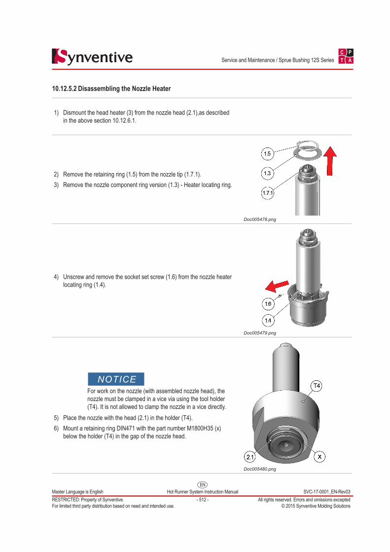
10.12.5.2 Disassembling the Nozzle Heater
1) Dismount the head heater (3) from the nozzle head (2.1),as described in the above section 10.12.6.1.
2) Remove the retaining ring (1.5) from the nozzle tip (1.7.1).3) Remove the nozzle component ring version (1.3) - Heater locating ring.
Doc005478.png
4) Unscrew and remove the socket set screw (1.6) from the nozzle heater locating ring (1.4).
Doc005479.png
NOTICEFor work on the nozzle (with assembled nozzle head), the nozzle must be clamped in a vice via using the tool holder (T4). It is not allowed to clamp the nozzle in a vice directly.
5) Place the nozzle with the head (2.1) in the holder (T4).6) Mount a retaining ring DIN471 with the part number M1800H35 (x)
below the holder (T4) in the gap of the nozzle head.
Doc005480.png
EN
C P
T A
Master Language is English Hot Runner System Instruction Manual SVC-17-0001_EN-Rev03RESTRICTED: Property of Synventive. - 513 - All rights reserved. Errors and omissions exceptedFor limited third party distribution based on need and intended use. © 2015 Synventive Molding Solutions
Service and Maintenance / Sprue Bushing 12S Series
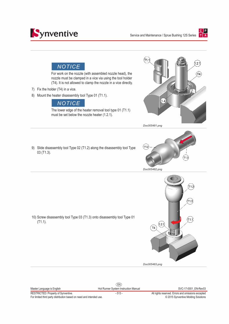
NOTICEFor work on the nozzle (with assembled nozzle head), the nozzle must be clamped in a vice via using the tool holder (T4). It is not allowed to clamp the nozzle in a vice directly.
7) Fix the holder (T4) in a vice.8) Mount the heater disassembly tool Type 01 (T1.1).
NOTICEThe lower edge of the heater removal tool type 01 (T1.1) must be set below the nozzle heater (1.2.1).
Doc005481.png
9) Slide disassembly tool Type 02 (T1.2) along the disassembly tool Type 03 (T1.3).
Doc005482.png
10) Screw disassembly tool Type 03 (T1.3) onto disassembly tool Type 01 (T1.1).
Doc005483.png
EN
C P
T A
Master Language is English Hot Runner System Instruction Manual SVC-17-0001_EN-Rev03RESTRICTED: Property of Synventive. - 514 - All rights reserved. Errors and omissions exceptedFor limited third party distribution based on need and intended use. © 2015 Synventive Molding Solutions
Service and Maintenance / Sprue Bushing 12S Series
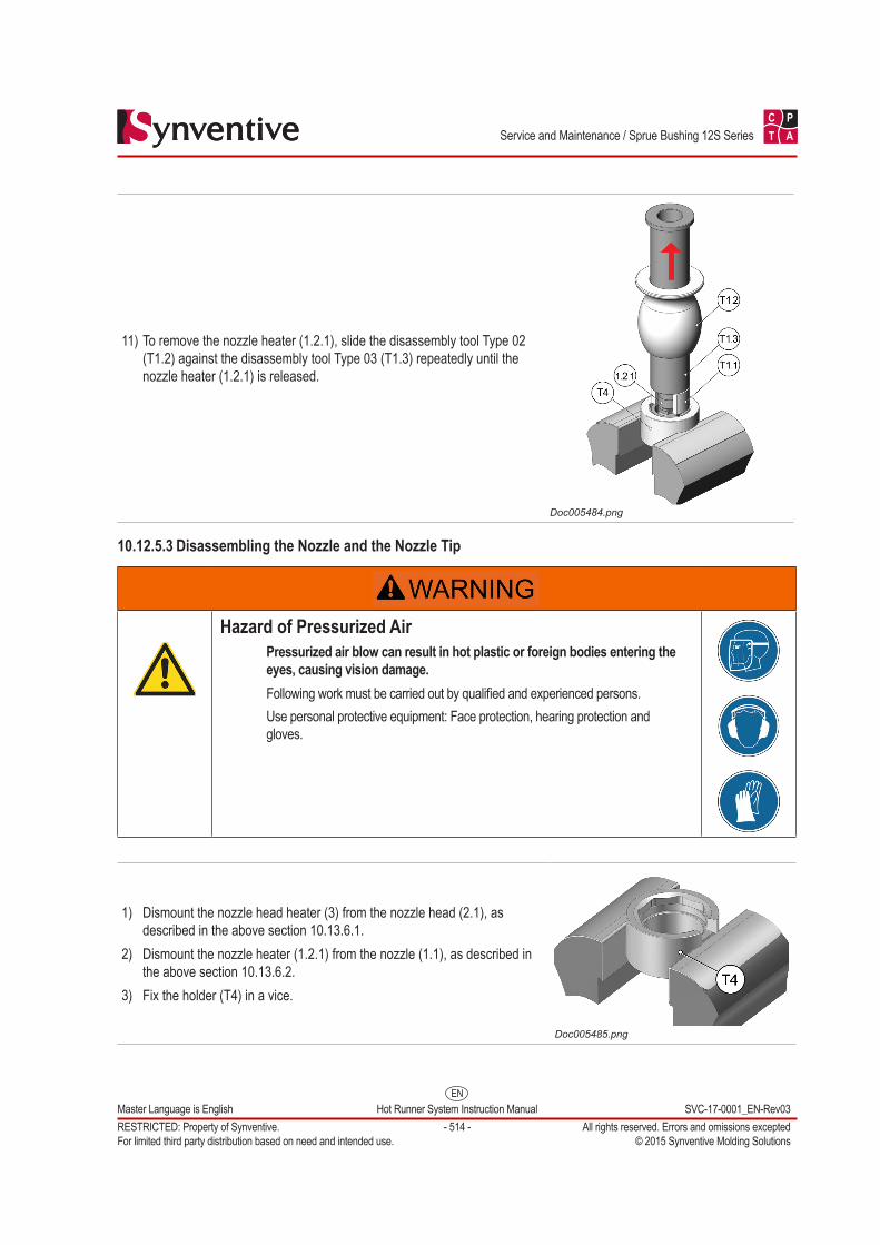
11) To remove the nozzle heater (1.2.1), slide the disassembly tool Type 02 (T1.2) against the disassembly tool Type 03 (T1.3) repeatedly until the nozzle heater (1.2.1) is released.
Doc005484.png
10.12.5.3 Disassembling the Nozzle and the Nozzle Tip
Hazard of Pressurized AirPressurized air blow can result in hot plastic or foreign bodies entering the eyes, causing vision damage.Following work must be carried out by qualified and experienced persons.Use personal protective equipment: Face protection, hearing protection and gloves.
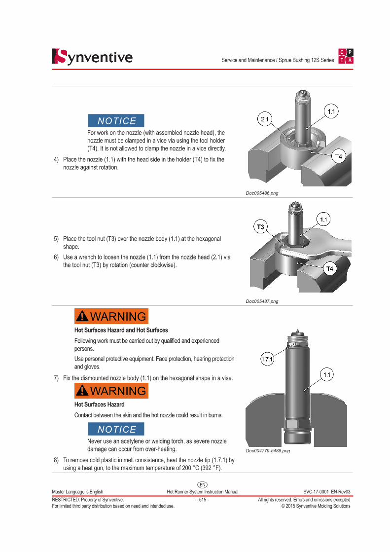
1) Dismount the nozzle head heater (3) from the nozzle head (2.1), as described in the above section 10.13.6.1.
2) Dismount the nozzle heater (1.2.1) from the nozzle (1.1), as described in the above section 10.13.6.2.
3) Fix the holder (T4) in a vice.
Doc005485.png
EN
C P
T A
Master Language is English Hot Runner System Instruction Manual SVC-17-0001_EN-Rev03RESTRICTED: Property of Synventive. - 515 - All rights reserved. Errors and omissions exceptedFor limited third party distribution based on need and intended use. © 2015 Synventive Molding Solutions
Service and Maintenance / Sprue Bushing 12S Series
NOTICEFor work on the nozzle (with assembled nozzle head), the nozzle must be clamped in a vice via using the tool holder (T4). It is not allowed to clamp the nozzle in a vice directly.
4) Place the nozzle (1.1) with the head side in the holder (T4) to fix the nozzle against rotation.
Doc005486.png
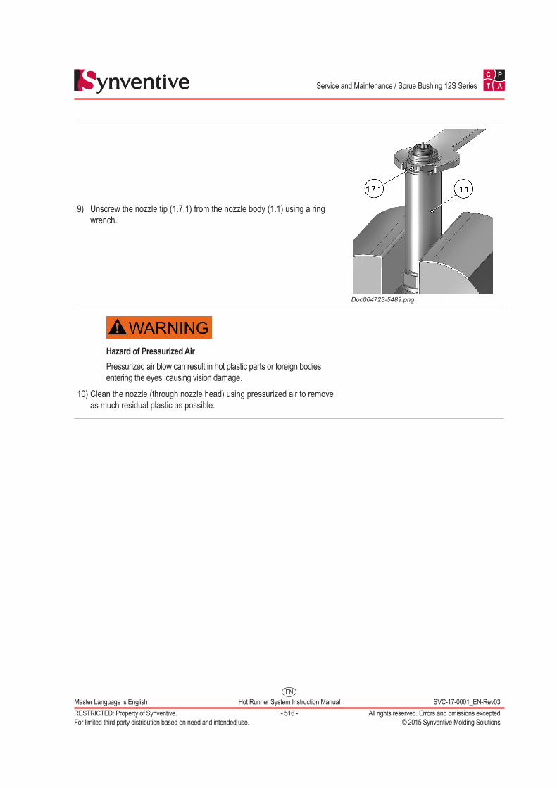
5) Place the tool nut (T3) over the nozzle body (1.1) at the hexagonal shape.
6) Use a wrench to loosen the nozzle (1.1) from the nozzle head (2.1) via the tool nut (T3) by rotation (counter clockwise).
Doc005487.png
Hot Surfaces Hazard and Hot SurfacesFollowing work must be carried out by qualified and experienced persons.Use personal protective equipment: Face protection, hearing protection and gloves.
7) Fix the dismounted nozzle body (1.1) on the hexagonal shape in a vise.
Hot Surfaces HazardContact between the skin and the hot nozzle could result in burns.
NOTICENever use an acetylene or welding torch, as severe nozzle damage can occur from over-heating.
8) To remove cold plastic in melt consistence, heat the nozzle tip (1.7.1) by using a heat gun, to the maximum temperature of 200 °C (392 °F).
Doc004779-5488.png
EN
C P
T A
Master Language is English Hot Runner System Instruction Manual SVC-17-0001_EN-Rev03RESTRICTED: Property of Synventive. - 516 - All rights reserved. Errors and omissions exceptedFor limited third party distribution based on need and intended use. © 2015 Synventive Molding Solutions
Service and Maintenance / Sprue Bushing 12S Series
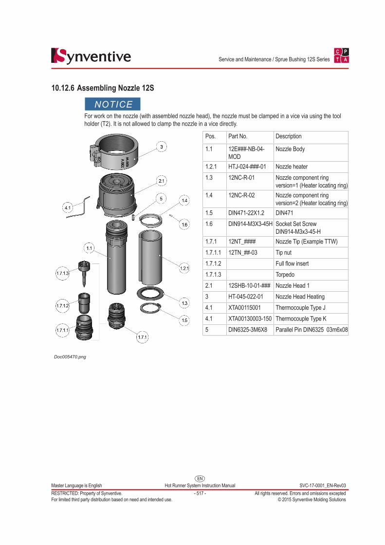
9) Unscrew the nozzle tip (1.7.1) from the nozzle body (1.1) using a ring wrench.
Doc004723-5489.png
Hazard of Pressurized AirPressurized air blow can result in hot plastic parts or foreign bodies entering the eyes, causing vision damage.
10) Clean the nozzle (through nozzle head) using pressurized air to remove as much residual plastic as possible.
EN
C P
T A
Master Language is English Hot Runner System Instruction Manual SVC-17-0001_EN-Rev03RESTRICTED: Property of Synventive. - 517 - All rights reserved. Errors and omissions exceptedFor limited third party distribution based on need and intended use. © 2015 Synventive Molding Solutions
Service and Maintenance / Sprue Bushing 12S Series
10.12.6 Assembling Nozzle 12S
NOTICEFor work on the nozzle (with assembled nozzle head), the nozzle must be clamped in a vice via using the tool holder (T2). It is not allowed to clamp the nozzle in a vice directly.
Doc005470.png
Pos. Part No. Description
1.1 12E###-NB-04-MOD
Nozzle Body
1.2.1 HTJ-024-###-01 Nozzle heater1.3 12NC-R-01 Nozzle component ring
version=1 (Heater locating ring) 1.4 12NC-R-02 Nozzle component ring
version=2 (Heater locating ring) 1.5 DIN471-22X1.2 DIN4711.6 DIN914-M3X3-45H Socket Set Screw
DIN914-M3x3-45-H1.7.1 12NT_#### Nozzle Tip (Example TTW)1.7.1.1 12TN_##-03 Tip nut1.7.1.2 Full flow insert1.7.1.3 Torpedo2.1 12SHB-10-01-### Nozzle Head 13 HT-045-022-01 Nozzle Head Heating4.1 XTA00115001 Thermocouple Type J4.1 XTA00130003-150 Thermocouple Type K5 DIN6325-3M6X8 Parallel Pin DIN6325 03m6x08
EN
C P
T A
Master Language is English Hot Runner System Instruction Manual SVC-17-0001_EN-Rev03RESTRICTED: Property of Synventive. - 518 - All rights reserved. Errors and omissions exceptedFor limited third party distribution based on need and intended use. © 2015 Synventive Molding Solutions
Service and Maintenance / Sprue Bushing 12S Series
10.12.6.1 Assembling the Nozzle Tip
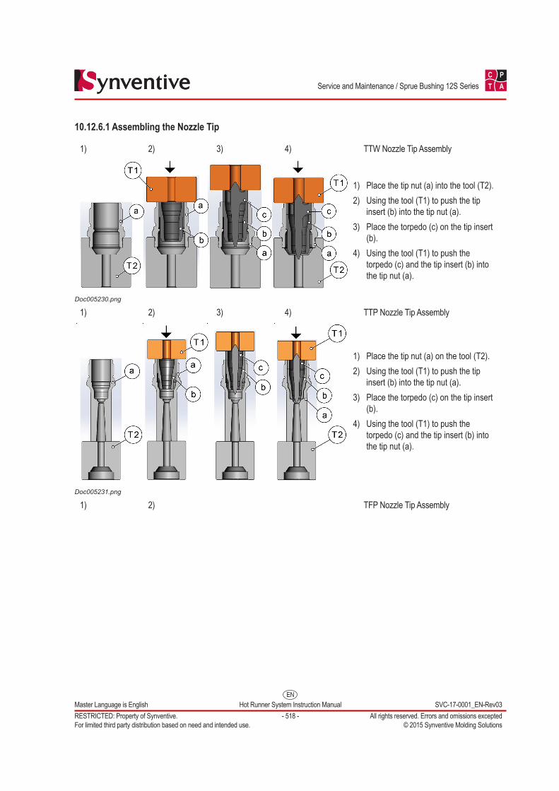
1) 2) 3) 4) TTW Nozzle Tip Assembly
Doc005230.png
1) Place the tip nut (a) into the tool (T2).2) Using the tool (T1) to push the tip
insert (b) into the tip nut (a).3) Place the torpedo (c) on the tip insert
(b).4) Using the tool (T1) to push the
torpedo (c) and the tip insert (b) into the tip nut (a).
1) 2) 3) 4) TTP Nozzle Tip Assembly
Doc005231.png
1) Place the tip nut (a) on the tool (T2).2) Using the tool (T1) to push the tip
insert (b) into the tip nut (a).3) Place the torpedo (c) on the tip insert
(b).4) Using the tool (T1) to push the
torpedo (c) and the tip insert (b) into the tip nut (a).
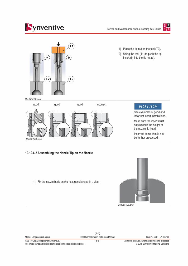
1) 2) TFP Nozzle Tip Assembly
EN
C P
T A
Master Language is English Hot Runner System Instruction Manual SVC-17-0001_EN-Rev03RESTRICTED: Property of Synventive. - 519 - All rights reserved. Errors and omissions exceptedFor limited third party distribution based on need and intended use. © 2015 Synventive Molding Solutions
Service and Maintenance / Sprue Bushing 12S Series
Doc005232.png
1) Place the tip nut on the tool (T2).2) Using the tool (T1) to push the tip
insert (b) into the tip nut (a).
good good good incorrect NOTICESee examples of good and incorrect insert installations.Make sure the insert must not exceeds the height of the nozzle tip head.Incorrect items should not be further processed.Doc004688.png
10.12.6.2 Assembling the Nozzle Tip on the Nozzle
1) Fix the nozzle body on the hexagonal shape in a vice.
Doc005520.png
EN
C P
T A
Master Language is English Hot Runner System Instruction Manual SVC-17-0001_EN-Rev03RESTRICTED: Property of Synventive. - 520 - All rights reserved. Errors and omissions exceptedFor limited third party distribution based on need and intended use. © 2015 Synventive Molding Solutions
Service and Maintenance / Sprue Bushing 12S Series
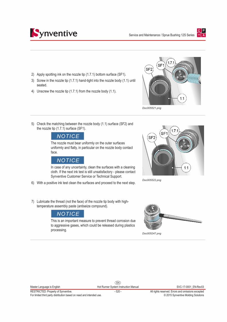
2) Apply spotting ink on the nozzle tip (1.7.1) bottom surface (SF1).3) Screw in the nozzle tip (1.7.1) hand-tight into the nozzle body (1.1) until
seated.4) Unscrew the nozzle tip (1.7.1) from the nozzle body (1.1).
Doc005521.png
5) Check the matching between the nozzle body (1.1) surface (SF2) and the nozzle tip (1.7.1) surface (SF1).
NOTICEThe nozzle must bear uniformly on the outer surfaces uniformly and flatly, in particular on the nozzle body contact face.
NOTICEIn case of any uncertainty, clean the surfaces with a cleaning cloth. If the next ink test is still unsatisfactory - please contact Synventive Customer Service or Technical Support.
6) With a positive ink test clean the surfaces and proceed to the next step.Doc005522.png
7) Lubricate the thread (not the face) of the nozzle tip body with high-temperature assembly paste (antiseize compound).
NOTICEThis is an important measure to prevent thread corrosion due to aggressive gases, which could be released during plastics processing.
Doc005247.png
EN
C P
T A
Master Language is English Hot Runner System Instruction Manual SVC-17-0001_EN-Rev03RESTRICTED: Property of Synventive. - 521 - All rights reserved. Errors and omissions exceptedFor limited third party distribution based on need and intended use. © 2015 Synventive Molding Solutions
Service and Maintenance / Sprue Bushing 12S Series
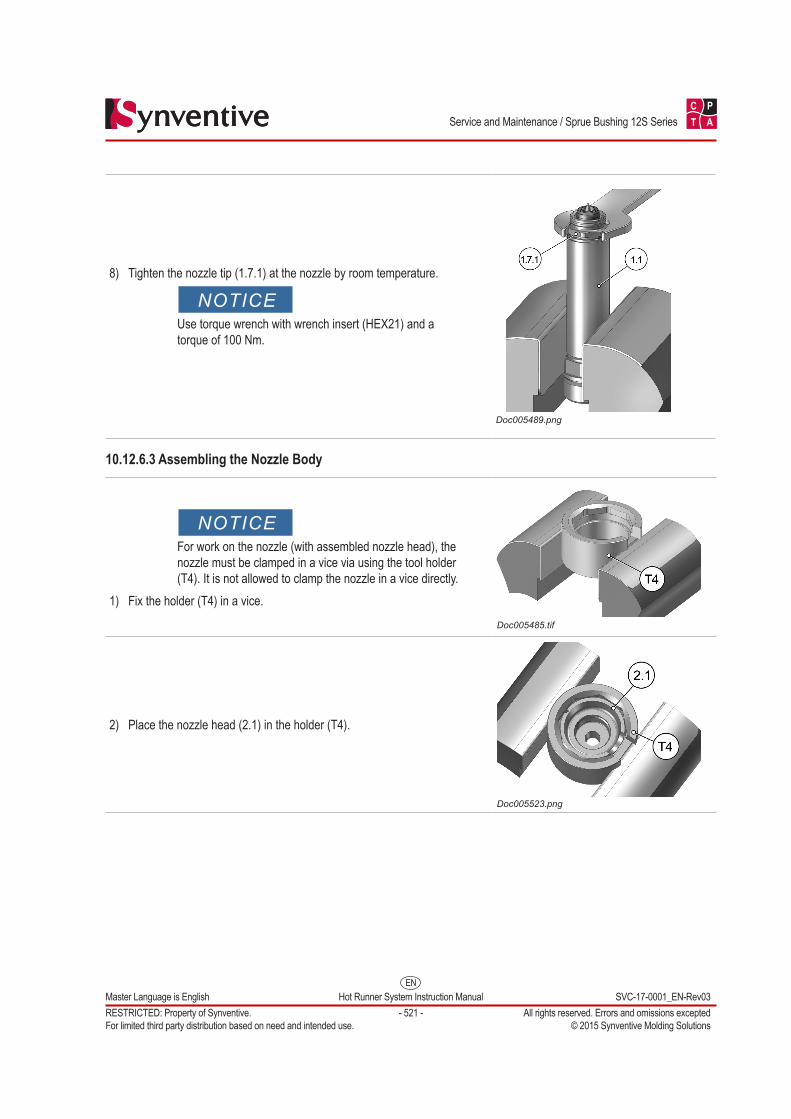
8) Tighten the nozzle tip (1.7.1) at the nozzle by room temperature.
NOTICEUse torque wrench with wrench insert (HEX21) and a torque of 100 Nm.
Doc005489.png
10.12.6.3 Assembling the Nozzle Body
NOTICEFor work on the nozzle (with assembled nozzle head), the nozzle must be clamped in a vice via using the tool holder (T4). It is not allowed to clamp the nozzle in a vice directly.
1) Fix the holder (T4) in a vice.Doc005485.tif
2) Place the nozzle head (2.1) in the holder (T4).
Doc005523.png
EN
C P
T A
Master Language is English Hot Runner System Instruction Manual SVC-17-0001_EN-Rev03RESTRICTED: Property of Synventive. - 522 - All rights reserved. Errors and omissions exceptedFor limited third party distribution based on need and intended use. © 2015 Synventive Molding Solutions
Service and Maintenance / Sprue Bushing 12S Series
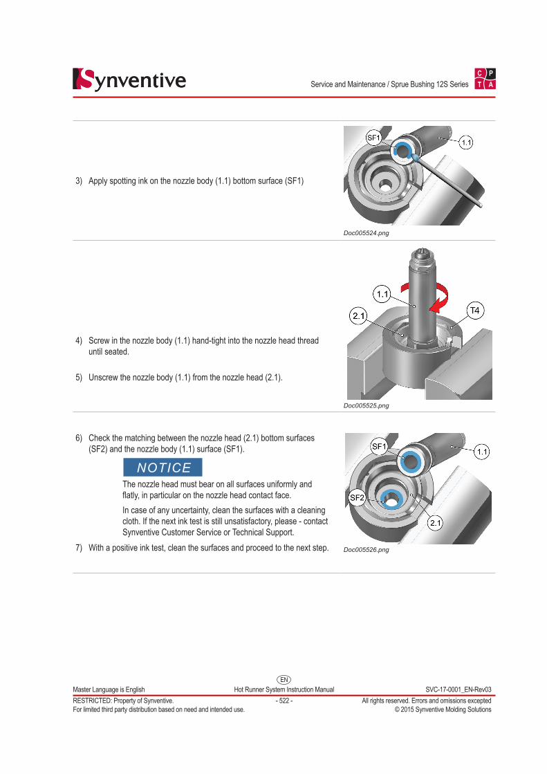
3) Apply spotting ink on the nozzle body (1.1) bottom surface (SF1)
Doc005524.png
4) Screw in the nozzle body (1.1) hand-tight into the nozzle head thread until seated.
5) Unscrew the nozzle body (1.1) from the nozzle head (2.1).
Doc005525.png
6) Check the matching between the nozzle head (2.1) bottom surfaces (SF2) and the nozzle body (1.1) surface (SF1).
NOTICEThe nozzle head must bear on all surfaces uniformly and flatly, in particular on the nozzle head contact face.In case of any uncertainty, clean the surfaces with a cleaning cloth. If the next ink test is still unsatisfactory, please - contact Synventive Customer Service or Technical Support.
7) With a positive ink test, clean the surfaces and proceed to the next step. Doc005526.png
EN
C P
T A
Master Language is English Hot Runner System Instruction Manual SVC-17-0001_EN-Rev03RESTRICTED: Property of Synventive. - 523 - All rights reserved. Errors and omissions exceptedFor limited third party distribution based on need and intended use. © 2015 Synventive Molding Solutions
Service and Maintenance / Sprue Bushing 12S Series
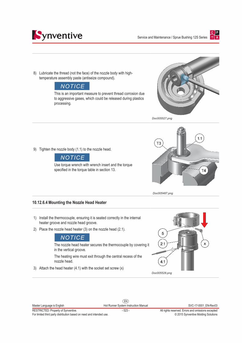
8) Lubricate the thread (not the face) of the nozzle body with high-temperature assembly paste (antiseize compound).
NOTICEThis is an important measure to prevent thread corrosion due to aggressive gases, which could be released during plastics processing.
Doc005527.png
9) Tighten the nozzle body (1.1) to the nozzle head.
NOTICEUse torque wrench with wrench insert and the torque specified in the torque table in section 13.
Doc005487.png
10.12.6.4 Mounting the Nozzle Head Heater
1) Install the thermocouple, ensuring it is seated correctly in the internal heater groove and nozzle head groove.
2) Place the nozzle head heater (3) on the nozzle head (2.1).
NOTICEThe nozzle head heater secures the thermocouple by covering it in the vertical groove.The heating wire must exit through the central recess of the nozzle head.
3) Attach the head heater (4.1) with the socket set screw (x)Doc005528.png
EN
C P
T A
Master Language is English Hot Runner System Instruction Manual SVC-17-0001_EN-Rev03RESTRICTED: Property of Synventive. - 524 - All rights reserved. Errors and omissions exceptedFor limited third party distribution based on need and intended use. © 2015 Synventive Molding Solutions
Service and Maintenance / Sprue Bushing 12S Series
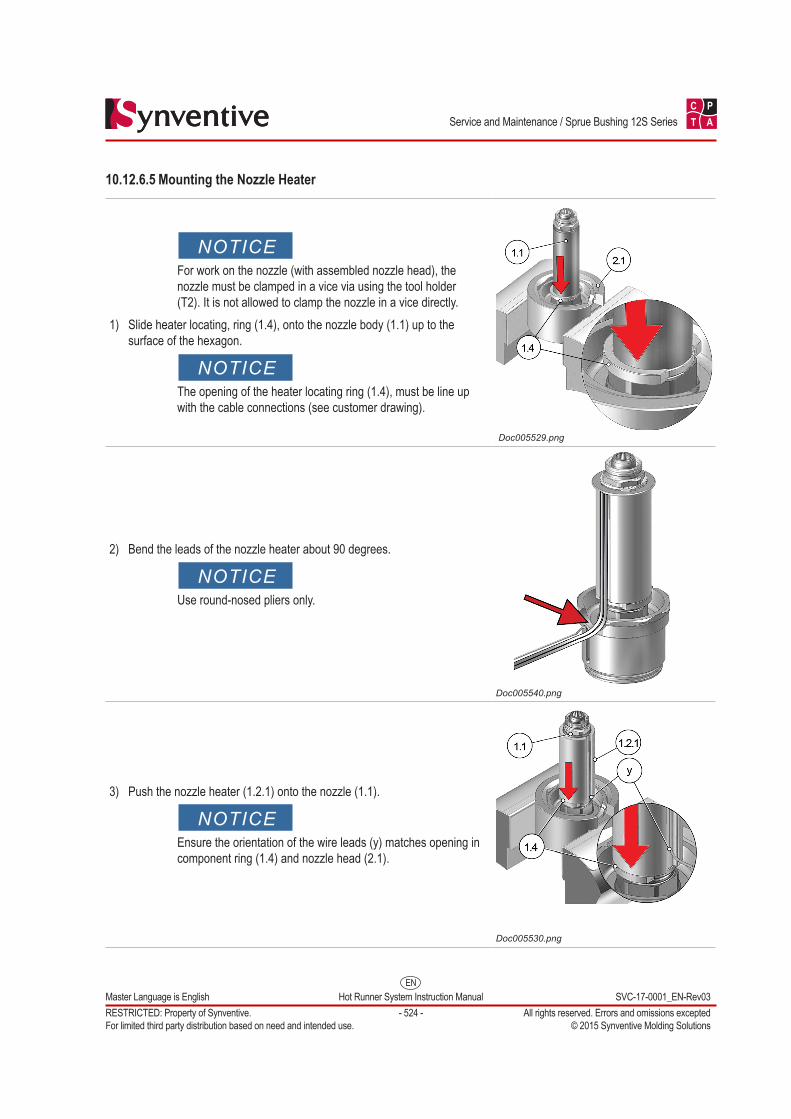
10.12.6.5 Mounting the Nozzle Heater
NOTICEFor work on the nozzle (with assembled nozzle head), the nozzle must be clamped in a vice via using the tool holder (T2). It is not allowed to clamp the nozzle in a vice directly.
1) Slide heater locating, ring (1.4), onto the nozzle body (1.1) up to the surface of the hexagon.
NOTICEThe opening of the heater locating ring (1.4), must be line up with the cable connections (see customer drawing).
Doc005529.png
2) Bend the leads of the nozzle heater about 90 degrees.
NOTICEUse round-nosed pliers only.
Doc005540.png
3) Push the nozzle heater (1.2.1) onto the nozzle (1.1).
NOTICEEnsure the orientation of the wire leads (y) matches opening in component ring (1.4) and nozzle head (2.1).
Doc005530.png
EN
C P
T A
Master Language is English Hot Runner System Instruction Manual SVC-17-0001_EN-Rev03RESTRICTED: Property of Synventive. - 525 - All rights reserved. Errors and omissions exceptedFor limited third party distribution based on need and intended use. © 2015 Synventive Molding Solutions
Service and Maintenance / Sprue Bushing 12S Series
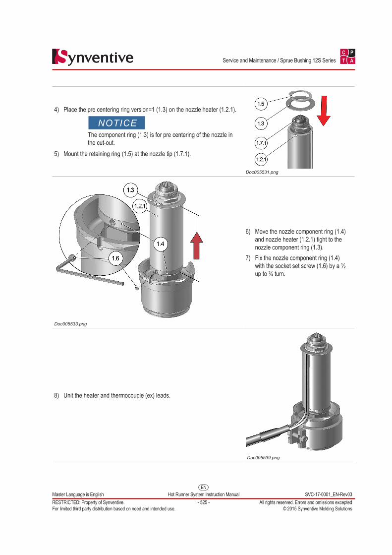
4) Place the pre centering ring version=1 (1.3) on the nozzle heater (1.2.1).
NOTICEThe component ring (1.3) is for pre centering of the nozzle in the cut-out.
5) Mount the retaining ring (1.5) at the nozzle tip (1.7.1).
Doc005531.png
Doc005533.png
6) Move the nozzle component ring (1.4) and nozzle heater (1.2.1) tight to the nozzle component ring (1.3).
7) Fix the nozzle component ring (1.4) with the socket set screw (1.6) by a ½ up to ¾ turn.
8) Unit the heater and thermocouple (ex) leads.
Doc005539.png