101 Articles Index - SPE Thermoforming Division...radiation. Includes discussion of where these heat...
44
17-3 Thermoformable Polymers This article features a short description of the two basic categories of polymers (thermoplastic and thermoset) and the two types of polymers (amorphous and crystalline). An explanation of the “thermoforming window” or temperature range in which a polymer can be formed is also discussed. 17-4 Polymer Properties This is a more technical article covering material modulus, stress, strain and melt index in a theoretical discussion of the characteristics of the material to be thermoformed. 18-1 Polymer Properties II This is a continuation of the previous article but deals more with the thermal properties of polymers and measurement of “heat capacity” or “specific heat.” It gets into more advanced concepts of thermal conductivity and thermal diffusion. These 2 articles are for those who need to understand the theory of polymers’ reaction to heat. 18-2 Basic Heat Transfer A basic description of the three modes of heat transfers: conduction, convection and radiation. Includes discussion of where these heat sources occur in thermoforming. 18-3 Mold Materials In this article the reader will learn about the types of materials used in thermoform molds, their qualities and when to use them. 18-4 Heaters Types of heat sources are described with an explanation of how they transfer energy. 19-1 Oven Design The role of the oven, the various oven designs and types available as well as the controls used to regulate oven temperature. 19-2 The Forming Temperature This is a key article on the subject of the right temperature to get optimum forming results. Upper and lower sheet temperature limits and heating the inner thickness of the sheet is discussed. ➤ 101 Articles Index The collection of articles in this book is listed in chronological order with a summary of each one for easy reference. The first article appeared in the fall of 1998 and they continued in every Thermoforming Quarterly until the third quarter 2007.
Transcript of 101 Articles Index - SPE Thermoforming Division...radiation. Includes discussion of where these heat...

[This is one in a series of articles introducing general concepts in thermoforming.] �
17-3 Thermoformable PolymersThis article features a short description of the two basic categories of polymers (thermoplastic and thermoset) and the two types of polymers (amorphous and crystalline). An explanation of the “thermoforming window” or temperature range in which a polymer can be formed is also discussed.
17-4 Polymer PropertiesThis is a more technical article covering material modulus, stress, strain and melt index in a theoretical discussion of the characteristics of the material to be thermoformed.
18-1 Polymer Properties IIThis is a continuation of the previous article but deals more with the thermal properties of polymers and measurement of “heat capacity” or “specific heat.” It gets into more advanced concepts of thermal conductivity and thermal diffusion. These 2 articles are for those who need to understand the theory of polymers’ reaction to heat.
18-2 Basic Heat TransferA basic description of the three modes of heat transfers: conduction, convection and radiation. Includes discussion of where these heat sources occur in thermoforming.
18-3 Mold MaterialsIn this article the reader will learn about the types of materials used in thermoform molds, their qualities and when to use them.
18-4 HeatersTypes of heat sources are described with an explanation of how they transfer energy.
19-1 Oven DesignThe role of the oven, the various oven designs and types available as well as the controls used to regulate oven temperature.
19-2 The Forming TemperatureThis is a key article on the subject of the right temperature to get optimum forming results. Upper and lower sheet temperature limits and heating the inner thickness of the sheet is discussed.
➤ 101 Articles IndexThe collection of articles in this book is listed in chronological order with a summary of each one for easy reference. The first article appeared in the fall of 1998 and they continued in every Thermoforming Quarterly until the third quarter 2007.
TF101 Insides 07.indd 1 9/25/07 8:55:25 AM
[This is one in a series of articles introducing general concepts in thermoforming.] �
19-3 Stretching the Sheet - Part IThis is the first of three parts dealing with sheet behavior during heating and forming. This part focuses on sheet behavior while it is still in the oven.
19-4 Stretching the Sheet - Part IIThis is the second of a series of three parts on stretching the sheet. This part deals with the draw-down of the hot sheet into a mold and its relationship to the stress-strain behavior of the plastic.
20-1 Stretching the Sheet - Part IIIThe final part of this three-part series deals with the pre-stretching of the sheet pneumatically or mechanically (blowing a bubble or assisting with a plug).
20-2 Cooling the Formed PartCooling the formed part while on the mold is second only to heating the sheet in getting quality parts. Maintaining mold temperature and additional cooling techniques are discussed.
20-3 Trimming - Part I: General CommentsThis article is the first of three parts on trimming. Because trimming of thin- and heavy-gauge parts covers a wide range of techniques and tools, they are dealt with in separate articles. The first deals with some generalities related to how plastics can be trimmed and what needs to be considered prior to deciding how to trim the part out of the formed sheet.
20-4 Trimming - Part II: Thin-GaugeThe second of three parts on trimming deals with processes used to trim thin-gauge parts and the types of cutting tools used.
21-1 Trimming – Part III: Thick-GaugeFinally, the trimming of thick-gauge parts from the formed sheet is the last in this series. Various types of trim tools and techniques are discussed.
21-2 Collecting Thin-Gauge PartsThin-gauge parts must be stripped from the sheet by hand or by mechanical means. This article describes the equipment and methods by which this is done.
21-3 What Part of “Regrind” Don’t You Understand?This is an in-depth look at an intrinsic characteristic of all thermoforming: the material that surrounds the formed and trimmed part that must be ground and reprocessed into sheet or other products.
21-4 How to Interpret Technical ArticlesThe author of most of the 101 articles, Dr. Jim Throne, added this discussion about the need to understand more complex, technical aspects of thermoforming. It is an advanced view of why technical articles must contain the theoretical information to provide the credibility for what have become accepted practices in our industry.
TF101 Insides 07.indd 2 9/25/07 8:55:26 AM

[This is one in a series of articles introducing general concepts in thermoforming.] �
22-1 In the BeginningThis article is an excellent summary of the very early forms of thermoforming and how they progressed. Statistics related to our industry and the process and market categories generally related to it are listed to give the reader a good overview.
22-2 Square One: Polymer SelectionAdditional material characteristics of those discussed in earlier articles are needed to produce quality thermoformed parts. This article plus the next two go into more detail with respect to the various characteristics of polymers. Extrusion basics such as melt viscosity and orientation are introduced in this article.
22-3 Square One: Polymer Selection-OrientationThis is a continuation of the previous article on the extrusion process with attention given to orientation of the sheet, testing for orientation and the comparison of orientation and shrinkage.
22-4 Square One: Observe Your Sheet as it HeatsThis final article of three discusses how we can observe the effects of orientation as the sheet is being heated and cooled during extrusion and thermoforming.
23-1 Recrystallization – What Does That Mean?This is a study of the crystalline and semi-crystalline materials such as PP, CPET and HDPE and what happens to these materials as they are heated.
23-2 Alphabet SoupThis title is misleading in that this article and the two following explain the meaning of the acronyms used in thermoforming. Tg, Tm and DSC refer to glass transition, melting temperature and differential scanning calorimeter, respectively. It is quite advanced in terms of chemical terminology but does relate to thermoformable polymers.
23-3 ABCs of Alphabet SoupThe second in a three-part series, this is a very technical article related to IR and FTIR or infrared energy and Fourier transformation respectively, as they relate to heat in the thermoforming process.
23-4 XYZs of Alphabet SoupContinuing from the previous two articles, this explains the meaning of HDT, DTA and DTMA (or, heat deflection temperature, differential thermal analysis and differential thermal mechanical analysis, respectively).
24-1 Why Part Design is ImportantThis article covers the many do’s and don’ts of part design. It is of prime importance for thermoformers to know the limitations of the process.
24-2 Comparing Concept to RealityThe limitations of thermoforming are dealt with in more detail. Also it discusses how to deal with customers from the most knowledgeable to the technically naïve. Working with the customer to determine the right material and design for his product as well as educating him on the advantages and limitations are covered.
TF101 Insides 07.indd 3 9/25/07 8:55:26 AM

[This is one in a series of articles introducing general concepts in thermoforming.] �
24-3 Understanding How a Sheet StretchesAssuming we have just received an order for a new job, this article deals with the decision to design the tooling as female or male. Also, the question of running the mold on top or on the bottom is addressed.
24-4 The Ubiquitous Draw Ratio“Draw ratio” is a term in thermoforming commonly used to describe the depth of a female cavity to its width at the narrowest point or the height of a protrusion on a male part in relation to another protrusion close to it. We learn about several methods of measuring draw ratio here.
25-1 Draft AnglesBecause material shrinks during the cooling process, draft angles are important in the part design. Here we learn about the draft angles required in various situations.
25-2 CornersCorners in a thermoformed part should be designed to avoid material thinning (in a female part). This sometimes conflicts with the design requirements or volume calculations of a container. This is discussed in general terms here.
25-3 The Cutting EdgeThe edge of the part directly after trimming can be less than clean. This article deals with what trimming methods produce the best results and how to finish the part after trimming to produce a better edge.
25-4 The RimThis article covers the design of the periphery of the part commonly referred to as the rim. The rim rolling process, detents for lid locking and de-nesting features are discussed as are the “dam” design, the hidden trim line and what happens to a textured sheet in the rim area.
26-1 Process – Cycle TimeImprovements in cycle time can have a big impact on your costs. This article deals with the different segments of the forming process and how these segments can be shortened.
26-2 Down Gauging – It’s a Good ThingThis is a look at why we quote starting gauge and how we could sell differently by agreeing with the customer on the wall thickness requirements of his part.
26-3 The Impossible Draw RatioDifficult draw ratios can be overcome by designing tooling with pre-draw boxes and plug assists. This article details an example of a difficult part and suggests a tool design.
TF101 Insides 07.indd 4 9/25/07 8:55:26 AM

[This is one in a series of articles introducing general concepts in thermoforming.] �
A TECHNICAL ARTICLE 1998 VOLUME 17, #3
Thermoformable PolymersAlthough we generally consider the words
“plastics” and ”polymers” interchangeable, the term “plastics” refers to the product delivered as resin pellets or sheet. Nearly all plastics contain “polymers,” the pure long-chain hydrocarbons, but they also contain shopping lists of additives such as thermal stabilizers,
antioxidants, color correcting dyes, internal and external processing aids, as well as product-specific additives such as fire retardants, colorants, UV stabilizers and fillers. However, because the term “plastic” connotes cheapness and poor quality, the industry is now calling all poly-meric materials “polymers.”
There are two general categories of polymers. When the polymer can be heated and shaped many times without substantial change in its characteristic, it is a “thermoplas-tic.” When the polymer cannot be reshaped after being heated and shaped the first time, it is a “ther-moset.” Thermoforming is primarily concerned with thermoplastics.
Thermoformers use two general types of polymers. When a polymer is heated from very low tempera-ture, it undergoes a transition from its glassy state to a rubbery state. Although this transition occurs over several degrees of temperature, usually only one temperature value is reported as the “glass transition temperature.” Polymers that only have a glass transition temperature are called “amorphous polymers.” Polystyrene, ABS, PVC and polycar-bonate are examples of amorphous polymers. 80% of all polymers ther-moformed are amorphous polymers. 80% of all amorphous polymers are styrenic, that is, polystyrene, impact polystyrene, ABS, and other similar polymers.
Certain polymers exhibit a second transition, from the rubbery state to a molten or melt state. Again, this tran-
sition occurs over several degrees of temperature, and again usually only one temperature value is reported as the “melt temperature.” Polymers that have both glass transition and melt temperatures are called “crys-talline polymers.” Polyethylene and polypropylene are examples of crys-talline polymers.
If only one polymer is used in a given plastic recipe, the polymer is called a “homopolymer.” Examples of homopolymers include general purpose polystyrene [GPPS or some-times called “crystal polystyrene” because parts made of the unpig-mented water-white polymer have the appearance of fine crystal], low-density polyethylene or LDPE and polyethylene terephthalate or PET. If one polymer is reacted with another, the polymer is called a “copolymer.” Impact polystyrene or HIPS is an example of polystyrene reacted with a rubber such as butadiene. Many copolymers are used in thermoform-ing, including polypropylene-poly-ethylene and PVC-PMMA.If three polymers are reacted together, the polymer is called a “terpolymer.” The classic terpolymer is ABS, which is a reacted product of Acrylonitrile, Butadiene and Styrene.
Occasionally, two poly-mers are extrusion- or melt-blended together to make a plastic recipe. The classic
blended polymer is modified poly-phenylene oxide or mPPO, which is a near-equal blend of polystyrene and polyphenylene oxide. mPPO is desired for its good impact resistance and fire retardancy.
The “thermoforming window” is the temperature range over which the polymer is sufficiently subtle or deformable for stretching and shaping into the desired shape. Typically, amorphous polymers have broader thermoforming windows than crystalline polymers. Polystyrene, for example, can be formed from around 260°F or about 50°F above its glass transition temperature to about 360°F or only a few degrees below the temperature where it is injection moldable. Polypropylene homopolymer, on the other hand, is so fluid above its melting temperature of 330°F that its thermoforming window may be no more than one degree or so. As a result, it is frequently formed just below its melting temperature. Even then,
its thermoforming window may be only two or three
degrees. ■
Keywords: amorphous, crystalline, glass transition temperature, melting temperature, homopolymer, copolymer, terpolymer, blend, thermoforming window
TF101 Insides 07.indd 5 9/25/07 8:55:27 AM

� [This is one in a series of articles introducing general concepts in thermoforming.]
A TECHNICAL ARTICLE 1998 VOLUME 17, #4
Polymer PropertiesThermoforming involves stretching of rub-
bery solid plastic sheet. When force is applied to any material, it stretches or elongates. The amount that it stretches depends on the amount of force per unit area, or “stress,” applied to the sheet, the nature of the material and its tem-perature. The amount that the material stretches
is elongation or “strain.” For most metals, ceramics and many polymers below their glass transition tempera-tures, the amount of strain in the ma-terial is proportional to the amount of stress applied to the material. The proportionality is referred to as the material “modulus.” The modulus of a given polymer depends on the molecular make-up of the polymer, the nature and level of the additives in the polymer and the temperature of the polymer. For example, according to Modern Plastics Encyclopedia, the ASTM D638 range in modulus of PS at room temperature [77°F or 25°C] is 330,000 to 475,000 psi.
For many polymers, the stress-strain curve is not linear, but is curved. The room temperature modu-lus for LDPE, for example, is oven in Modern Plastics Encyclopedia as 25,000 to 41,000 psi. But at room temperature, LDPE is far above its glass transition temperature of -25°C. Therefore, reported modulus is the slope of the stress-strain curve at zero strain. Furthermore, as the polymer is heated above its glass transition temperature, the stress-strain curve remains curved but flattens. The modulus, being the slope of the curve at zero strain, also decreases with increasing temperature. In addition, the elongation at break increases with increasing temperature.
The decreasing modulus, the flat-tening of the stress-strain curve, and the increasing elongation at break of a given polymer or polymer recipe with increasing temperature are all important in thermoforming, because the sheet must be stretched into the deepest recesses of a mold. Two other aspects of the stress-strain charac-teristics of a given polymer are also
important, however. If the softening range of the polymer is too narrow, that is, the polymer goes from being very stiff to extremely soft over a very narrow temperature range, the thermoforming window will be very narrow. This is the case with most grades of nylon 6, for example. And if the stress or force per unit area needed to stretch the polymer is always very high, regardless of the polymer tem-perature, traditional vacuum forming and even normal pressure forming pressures may be insufficient to stretch the polymeric sheet to the far-thest reaches of the mold. This is the case for many classes of highly filled and fiber-reinforced polymers.
Again, thermoforming focuses on the solid properties of a polymer, such as stress-strain. Nevertheless the fluid properties of the polymer are impor-tant as well. After all, the polymer must be extruded into sheet. Fluid properties of polymers are related to the polymer liquid resistance to applied stress. The polymer liquid resistance is given as “rate of strain” and “viscosity” is the slope of the stress-rate of strain curve. As with solid polymer stress-strain curves, liquid polymer stress-rate of strain curves are tem-perature dependent, with polymer viscos-ity decreasing with increasing temperature. Very high viscosity, being a measure of the polymer liquid resistance to applied stress, can lead tosheet extrusion problems. So can very low viscosity. Unwanted
orientation and internal stresses in sheet can be traced back to the vis-cosity of the polymer at the time of extrusion.
Frequently thermoformers are told to use a polymer with a given “melt index.” The melt index test was estab-lished years ago as a quick check of the flowability of polyethylene melt. Basically it is the amount of molten plastic, in grams, at a prescribed temperature that can be squeezed through a hole of a given diameter in ten minutes. Ten grams of a poly-ethylene with a melt index of 10, say, will extrude through the hole in ten minutes, whereas only 1 gram of a polyethylene with a melt index of 1 will extrude through the same hole in the same period of time. Thus, the polymer with the greater melt index value will flow more rapidly at the same stress level and therefore, will have a lower viscosity. For a given type of polymer, a lower viscosity usually means a lower molecular weight. Extruders prefer polymers with relatively high melt indexes. Keep in mind, however, that melt
index gives very little informa-tion about temperature- and
shear rate-dependent nature of the viscosity of a given polymer. And extending the concept of melt index beyond polyethylenes and polypropylenes is risky, at best. ■
Keywords: modulus, viscosity, stress, strain, stress-strain curve, stress-rate of strain curve, melt index
TF101 Insides 07.indd 6 9/25/07 8:55:28 AM

[This is one in a series of articles introducing general concepts in thermoforming.] �
A TECHNICAL ARTICLE 1999 VOLUME 18, #1
Polymer Properties IIIn addition to stress-strain and stress-rate
of strain characteristics of polymers, thermo- formers need to know about the thermal prop-erties of polymers.
“Heat capacity” is a measure of the amount of energy required to elevate the polymer tem-perature. Heat capacity is sometimes called
“specific heat.” The field of study that focuses on energy uptake of ma-terials is called “Thermodynamics.” In thermodynamics, one of the fun-damental measures of energy uptake is “enthalpy.” Enthalpy increases with increasing temperature. When a material goes through a charac-teristic change such as melting, the temperature-dependent enthalpic curve changes dramatically. When a material goes through a character-istic change such as glass-to-rubber transition, the temperature-depen-dent enthalpic curve changes subtly if at all. As expected, it takes far more energy to heat a crystalline polymer from room temperature, say, to above its melt temperature than to heat an amorphous polymer from room temperature to the same tem-perature. For example, it takes more than twice as much energy to heat polyethylene, a crystalline polymer, to 360°F than it does to heat poly-styrene to the same temperature. And since the formed shape must be cooled, twice as much energy must be removed to cool polyethylene to a given temperature than to cool polystyrene to the same tempera-ture. A single value of specific heat is frequently given for a specific poly-mer. These values are determined by dividing the enthalpy difference by the temperature difference. Such values are acceptable for amorphous polymers but care must be taken with a crystalline polymer, since the slope of the temperature-dependent enthalpy curve, and hence the spe-cific heat, changes dramatically as
the temperature approaches the melt temperature of the polymer.
“Thermal conductivity” is the measure of energy transmission through a material. The thermal conductivity values of organics, in general, are substantially lower, by orders of magnitude, than, say, metals. In other words, polymers are thermal insulators. As an ex-ample, the thermal conductivity of aluminum, a common metal for thermoforming molds, is one-thou-sand times greater than the thermal conductivity of, say, polystyrene. During thermoforming, thermal conductivity is a measure of energy transmission through the polymer sheet. Even though the thermal conductivities of polymers are low, there are differences in values among polymers. For instance, the thermal conductivity of HDPE is about four times higher than polystyrene or ABS. Thermal conductivity and its companion property, thermal dif-fusivity, discussed below, are quite important when forming very thick sheets, because the rate of energy transfer into the sheet gov-erns, to a large e x t e n t , t h e formability of the sheet. Although thermal conductivity typically decreases slightly with increasing temperature, for all intents, the value can be considered constant.
Polymer density decreases and its reciprocal, “specific volume,” increases with increasing tempera-ture. In the vicinity of the glass tran-
sition temperature, the slope of the temperature-dependent specific vol-ume curve changes perceptively. In the vicinity of the melt temperature, the slope changes dramatically. Typi-cally, the density of an amorphous polymer at its forming temperature is about 10% to 15% less than that at room temperature. The density of a crystalline polymer at its form-ing temperature may be as much as 25% less than that at room tem-perature. Obviously as the polymer cools from its forming temperature, its density will increase, its volume will decrease, the final part dimen-sions will decrease and the part will exhibit shrinkage. This point will be amplified in later articles. “Thermal diffusivity” is a poly-mer property that is a combina-tion of other polymer properties. Thermal diffusivity is divided by its density and specific heat, and is the fundamental polymer property in time-dependent heat transfer to materials. Because of the unique
bundling of temperature- dependent characteris-
tics of the polymer properties, thermal diffusivity is nearly independent of tem-perature for nearly all polymers.
■Keywords:Heat capacity, specific heat, enthalpy, thermal conductivity, specific volume, thermal diffusivity
TF101 Insides 07.indd 7 9/25/07 8:55:28 AM

� [This is one in a series of articles introducing general concepts in thermoforming.]
A TECHNICAL ARTICLE 1999 VOLUME 18, #2
Basic Heat Transfer
Thermoforming involves first adding energy to plastic sheet to elevate its temperature to a form-ing temperature, then forming the sheet against a mold, then cooling the formed sheet to a temperature where the part retains the shape of the mold. There are three modes of heat transfer which are important during the heating and cooling of the plastic.
“Conduction” is energy trans-mission through solid objects. In thermoforming, energy is conduct-ed from the surface of the polymer sheet to its interior during heating, and from its interior to its surface during cooling. As noted in an ear-lier article, the thermal conductivity or more properly, thermal diffusiv-ity of the polymer is the fundamen-tal property in determining the rate of energy transfer through the solid or rubbery polymer. The higher the thermal diffusivity of the polymer, the more rapidly energy is trans-ferred and the more uniform is the temperature through the polymer.
“Convection” is energy trans-mission between solid objects and fluids. In thermoforming, air is the fluid surrounding the sheet in the oven and typically in contact with the free surface of the formed part on the mold surface. Convec-tive energy transmission depends strongly on the flow rate of the fluid. The greater the flow rate, the greater the rate of energy transfer. The proportionality is called the
“heat transfer coeffi-cient.” Convective heat transfer is also impor-tant during the cooling of the plastic part on the mold surface, since the coolant running through the mold pip-ing is a fluid. Typically, the cooling efficiency of liquids is greater, by
an order of magnitude, than that for air. For example, cooling water is about one hundred times more effective in cooling than fan-blown air.
“Radiation” is energy inter-change between two solid objects having different temperatures. Unlike conduction, which requires direct contact between solid objects, and convention, which requires direct contact between fluids and solid objects, radiation is electro-magnetic energy transfer, requir-ing no contact. However, radiation energy transfer requires that the two objects “see” each other. In thermoforming, radiation energy transfer occurs in the oven between the heater surfaces and the sheet surface. It also occurs between heat-er surfaces and oven walls, clamp frames, and the outside world if the oven is open. Radiation energy transfer also occurs when the sheet is removed from the oven, since the sheet is hotter than its sur-roundings. How-ever, the amount of energy transfer is a function of the fourth power of the tempera-ture of the solid object and so radiant energy transmis-sion in the thermoforming oven is far more significant
than anywhere else in the process. Radiant energy intensity is usually identified in terms of object tem-perature or wavelength. Traditional thermoforming heaters operate between about 100°F and 1500°F, and have peak wavelengths of 2.5 to 9 microns. This range is referred to as “far intrared.”
First, it is important to realize that all three modes of heat transfer – conduction, convection and radia-tion – are important in the heating of thermoformable polymer sheets. The primary mode of energy trans-fer varies depending primarily but not exclusively on the thickness of the polymer sheet. Very thick sheets, 13 mm or 0.5 inch in thick-ness or thicker, can be heated rather efficiently in “pizza oven” heaters, where hot air is convected or blown around the sheet that is supported on all sides to allow for uniform cir-culation. Even though the air might be heated by being blown across hot panels, the primary modes of heat transfer are convection to the sheet surface and conduction of the energy into the volume of the sheet. At the other extreme, thin sheet, 0.75 mm or 0.030 inch in thickness, can be heated extremely rapidly with very intensive radiant heat, since conduction through thin sheet is very rapid.
All commercial energy sources used in thermo-forming today produce heat both by convection [hot air moving across the heater surface] and radia-tion heater surface temper-atures greater than sheet surface temperatures].
■
Keywords: conduction, convection, radiation, far infrared
TF101 Insides 07.indd 8 9/25/07 8:55:29 AM

[This is one in a series of articles introducing general concepts in thermoforming.] �
A TECHNICAL ARTICLE 1999 VOLUME 18, #3
Mold Materialsmanner as water lines are drilled in injection molds.
In certain instances, other metals are used for molds. For composites, for example, temperature and pres-sure requirements may preclude the use of aluminum. Steel, particularly chrome-plated steel, and stainless steel are good alternatives. Steel has about one-third the thermal conduc-tivity of aluminum and about twice the modulus. Stainless steel has about one-fifth the thermal conductivity of aluminum and about 50% greater modulus.
Because thermoforming pressures are relatively low, usually not exceed-ing 100 psi, many other materials can be used for molds. Although electroformed nickel is much more expensive than other metals, it is used when extremely high detail is needed or when a very intricate pattern must be replicated. Very large parts, such as exterior door panels, have been made on electroformed nickel tools. Usually nickel is electroformed onto a pattern, water lines are placed against the nickel shell, then the nickel is backed with a cheaper white metal.
Sprayed metal is also used for prototyping and limited produc-tion. Molten white metal such as zinc is atomized and atmospheri-cally sprayed against a pattern in a fashion similar to paint spraying or polyester spraying. A reasonably thick layer of metal can be sprayed in a reasonably short time. Water lines are placed against the metal shell and
sprayed in place. This is then backed wither with metal-filled epoxy or pot metal. Many sprayed metal applications have been taken over by com-puter-driven machining, and so typical sprayed metal molds today are small and highly detailed.
There are even more materials available for straight vacuum formed prototypeparts. Wood is an obvious choice , with ash and hard maple offering the best balance of properties such as compression strength, shaping and sanding quality and resistance to splitting, checking, and warping. Hydrocal is a dense industrial plaster that makes a high quality mold. Plas-ter mold fabrication is quick, with the primary drawbacks being the messy nature of plastic casting, including plastic dust, weight [compared with wood], and brittleness.
More recently, medium density fiberboard or MDF has found ex-tensive use, primarily for shallow draw and male molds, since it can be quickly worked with traditional woodworking tools and has no grain and no propensity to warp, split or check. It is relatively expensive and restricted in thickness. Syntactic epoxy or polyester foam was originally developed as a plug assist material but is now computer-driven machined into smaller molds. It can be expensive, particularly if a substan-tial amount of the initial billet must be machined away to make the mold.
■
Keywords: cast aluminum, machined aluminum, computer-driven machining, chrome-plated steel, stainless steel, electroformed nickel, hydrocal, medium density fiberboard, syntactic foam, sprayed metal
Most commercial thermoforming molds are made from aluminum. Aluminum is used because it is light, it is easily worked, is relatively inex-pensive and has a very high thermal conductivity. It is also used because the forming forces against the finished mold are low when compared with, say, injection molding.
Larger commercial molds are usu-ally cast from the melt. In addition to the common atmospheric casting, molds can be made by vacuum casting and pressure casting. Smaller molds are frequently machined from plate. Computer-controlled machining stations have made manufacture of many-cavity molds quite competitive with other means of manufacture.
For the most part, thermoforming molds are single-surfaced. That is, one surface of the plastic sheet is forced against the mold surface, while the other surface is “free” or untouched by another mold surface. In certain instances, such as foam and com-posite forming, the sheet is so stiff at the forming temperature that it must be pressed between two “matched mold” surfaces in order to accurately form the part.
In large, cast molds, water lines are typically attached to the reverse sides by soldering or secondary casting. In smaller, machined molds, cooling is frequently done through flood plates attached to the rear of the molds. When water lines are needed, for deeply drawn parts, they are gun-bore drilled in, in much the same
TF101 Insides 07.indd 9 9/25/07 8:55:30 AM

�0 [This is one in a series of articles introducing general concepts in thermoforming.]
A TECHNICAL ARTICLE 1999 VOLUME 18, #4
Heaters
There are three primary energy sources for heating plas-tic sheet in thermoforming. Electric heat is used more than gas heat or hot fluid heat. Some common heating sources include hot air, hot water or steam, sun lamps, nichrome spiral wire or toaster wire, steel rod heaters, steel or ni-chrome tape, tungsten and halogen tube heaters, quartz tube heaters with nichrome or tungsten wire or tape, steel plates with embedded resistance wire, ceramic plates with embedded resistance wire, ceramic bricks with embedded resistance wire, ceramic bricks with embedded resistance wire, steel plates that reradiate combustion energy from gas flame, indirect gas combustion on catalytic beds and direct gas combustion energy. Keep in mind that all hot surfaces transfer energy by conduction, convection and radiation.
Hot Fluid HeatingRecirculating hot air or forced convection ovens are used
when heating times are not critical or when sheet is very thick, usually greater than 0.500 inches. There are several oven designs in use. Air is blown across metal coils and then across the sheet in indirect electric ovens. Electric panels, usually in the top of the oven, are combined with fan-cir-culated air in direct electric ovens. Architectural products such as commercial or industrial skylights, soaking tubs and whirlpools are frequently made using these methods of heating. Direct gas-fired heaters similar to those used in rotational molding ovens, are used to heat plastics such as polyethylene that are not easily oxidized or chemically attacked by combustion products.
Direct Contact HeatingDirect contact heating is used extensively for very thin
sheet or thermally sensitive polymers. For a very short time, the sheet is brought in contact with a heated PTFE-coated metal plate. It is then quickly formed against the mold. Direct contact heating is a common heating method in form, fill and seal (FFS) machines, where the sheet may be heated sequentially on both sides, by running it against heated rolls. Oriented Pet such as Mylar™, oriented poly-styrene (OPS), nylon 6, 66 and 11, some calendered PVC, and cast polyimide such as Kapton™ are heated using direct contact heating.
Electric HeatersElectric heaters can be categorized as round heaters, such
as wire, rod or quartz heaters, and flat heaters such as panel heaters. Metal rod heaters have long heat-up times, tend
to age quickly, have poor temperature control, cannot be easily zoned, but are extremely rugged and relatively inex-pensive. Quartz and halogen heaters are basically nichrome or tungsten wires in quartz glass tubes. These heaters are known for their very short heat-up times, excellent tem-perature control, and very high temperature capability, but they are very fragile, the glass is easily etched, and they are very expensive. Panel heaters include coated metal plates that reradiate heat from nichrome wires embed-ded in ceramic, quartz glass and quartz cloth plates that transmit heat from similarly embedded nichrome wires. Panel heaters have moderately long heat-up times, good temperature control, and excellent longevity, but they are difficult to zone effectively. Ceramic bricks that have embedded heating wires are reasonably rugged, have moderate heat-up times, excellent temperature control and moderate longevity, but they are fragile and it is difficult to determine burn-out.
Combustion HeatingThe “2000 Years of Thermoforming” cartoon on the 1996
SPE Thermoforming Division tee-shirt depicted a caveman stomping on a sheet of plastic suspended over a roaring fire. Direct gas heating using natural gas or propane rather than wood is a viable way of heating plastic. However the energy output from direct combustion is very high and sheet scorching or ignition is always a concern. Indirect catalytic heaters provide a more uniform energy source, although energy output is admittedly less than that for electric heaters, and, until recently, temperature control was “on-off.” Installation cost is higher than that for elec-tric heaters, but energy costs are as low as 20% of that for equivalent output electric heaters. Catalyst longevity was problematical early on, but fourth generation catalysts ap-pear to have minimized loss in efficiency and formation of hot spots. High pressure indirect gas combustors known as ported surface burners are currently being tested as an alternative to the high-energy electric heaters.
Selection of the “Correct” HeaterThere is no “correct” heater. Heater
selection depends on many intrinsic and extrinsic factors including retrofit-ting, sheet geometric char-acteristics including thickness, polymer thermal sensitivity, day-to-day running costs, maintenance costs, initial in-stallation cost, versatility of the heater, and the inherent design of the thermoforming machine and its surroundings. ■
Keywords: Electric heat, gas heat, fluid heat, direct contact heat, nichrome, tungsten, quartz, halogen, catalytic heater
TF101 Insides 07.indd 10 9/25/07 8:55:30 AM

[This is one in a series of articles introducing general concepts in thermoforming.] ��
A TECHNICAL ARTICLE 2000 VOLUME 19, #1
Oven Design
THERMOFORMING101
Various types of heaters were de- scribed in an earlier tutorial. In
this lesson, the effect of the heat pro-duced by these heaters is considered. The focus is on non-contact heating.
The Role of The Oven The oven serves several purposes. It holds the sheet while it is being heated. For the most part, it isolates the heating sheet from the environment outside the oven. It provides a rigid structure for the heaters. It provides a way for the sheet to enter the oven and a way for it to exit the oven. And it provides fixed spacing between the sheet and the heaters. Most importantly, the oven must protect both the sheet and the heaters from thermal or mechanical damage, if something goes wrong. The simplest oven consists of a single heater bank suspended over a clamped sheet, with no provision for isolating the sheet from the outside environment. This heating method is sometimes used, even though the heat transmission from the heater to the sheet is quite poor. Heater efficiency is improved by shrouding the heater in sheet metal and covering that with several inches of fiberglass. At the other extreme, ovens are available that actively clamp, top and bottom, against the sheet, completely isolating it from the environment. These ovens are very energy efficient and can be quite expensive. Regardless of the type of heater used, the heaters are usually held in planes above and below the sheet plane. One thermoforming machinery manufacturer uses curved rod heaters, with the heaters curved downward
near the sheet edges. This helps minimize heater inefficiency along sheet edges. Usually the heaters are fixed in position relative to the sheet plane. However, machines have been built in which the lower heaters travel downward as the heating sheet sags. Most electric ovens operate on 480V/3Ø. Heaters are usually rated in “watt density,” with W/in2 being the standard U.S. dimension. Rod, panel, and ceramic heater watt densities are up to about 40 W/in2. Quartz heaters are available to 60 W/in2. Gas-fired heaters operate at gas pressures of about 5 to 10 ozs., although new ported burners require up to 5 lb/in2 gas pressure. All catalytic gas heaters also require electric preheaters, which can operate at 240V1Ø but are more efficient at 480V/3Ø. Catalytic gas heaters have equivalent watt densi-ties of up to about 30 W/in2. Ported burners and free-surface burners have equivalent watt densities of about 500 W/in2. Just as there is no ideal heater, there is no ideal oven design. An optimum oven design sufficiently iso-lates the sheet from the outside oven environment to minimize drafts and energy loss. But the design should allow for relatively easy means of transferring the sheet into and out of the oven. And it should allow for any sheet movement during heating, such as sag, by spacing bottom heaters away from the final sheet shape.
Controls Oven controls range from simple on-off electrical switches to tem-perature-sensed proportional and proportional-integral-derivative or PID controllers. Oven heaters can be ganged and operated from a single controller or individually connected to separate controls. Early ceramic heaters were sometimes individu-ally connected to individual ten-turn potentiometers or pots, yielding a
“B movie” science-fiction-like wall of hundreds of adjustable dials. Now, most small heaters are “clustered” into a more manageable number of controllable “zones” which are then adjustable through a digital or even touch-screen monitor at the process control station. PID controllers are a must for heaters that require rapid changes in power level. These con-trollers minimize power overshoot. This minimizes sheet overheating and extends the lifetime of the heater element Burning or decomposing plastic is always a concern in thermoform-ing. Ovens are usually designed with both passive and active means of minimizing damage due to a dropped sheet. At the very least, the bottom heater is protected with easily removed, inexpensive chicken-wire screen suspended above it. In certain instances, quartz plates are placed above the bottom heater. When pris-tine, quartz is transparent in infrared energy and so does not affect the heater efficiency. Since the quartz does not heat, the dropped sheet is quickly frozen by the cold plate, this facilitating sheet removal and mini-mizing damage to the lower heater. Sag monitors, really photoelectric sensors, detect excessive sag and can sound a klaxon, shut down the heat-ers, drop baffles in place, or activate oven pull-back or fly-open controls. In some oven designs, high-volume blowers, activated either by sag moni-tors or infrared sensors, blow room temperature air over the overheated sheet, either before it drops onto the heater or while it resides on the chicken-wire screen. In other designs, the oven cabin is flooded with carbon dioxide whenever fire is detected. Mechanically, ovens can be equipped with baffles or doors that isolate the heaters from the sheet, or the ovens may be clam-shell opened or hori-zontally retracted to remove the heat source from the sheet. ■
Keywords: Oven design, power requirements, watt density, fire control, heater control, on-off control, proportional control, PID control
TF101 Insides 07.indd 11 9/25/07 8:55:31 AM
�� [This is one in a series of articles introducing general concepts in thermoforming.]
A TECHNICAL ARTICLE 2000 VOLUME 19, #2
The Forming TemperatureIs the sheet ready to be formed?”
This is the most difficult question in all of thermoforming. Part of the difficulty lies in the broad spectrum of polymers and part designs. And part lies in the difficulty in determining what measurable physical property in the polymer best characterizes the polymer formability. As discussed in an earlier lesson, thermoforming is best described as a rubbery sheet stretching process. As a result, the elastic character of the polymer, re-flected in its temperature-dependent tensile strength and modulus, should give a strong clue. Methods of mea-suring and interpreting the elastic character are discussed in another lesson.
The Calibrated Eyeball But first, what about other methods of determining formability? As noted in an earlier lesson, sheet sag is a manifestation of lowering tensile strength. And sag is used by the experienced op-erator to gauge when a sheet is hot enough to be formed.All things equal, the sheet should sag the same amount at the same temperature, time in and time out. Sheet “thumping” or the manual manipulation of the sheet during the later heating stages is also a gauge. A screwdriver or key thrust into the corner of the sheet will also yield a “calibrated eyeball” assessment of formability. Other indicators are the change in gloss of the sheet surface and the nature of the “smoke”1 being evolved from the sheet. Of course, the trained observer must then cor-relate these experiential judgments with the extrinsic nature of the part that is being formed. In other words, deeply drawn parts probably require hotter sheet, which is then trans-lated by the operator into greater sag or more loss in gloss, and so on.
Upper and Lower Forming Temperatures Most references list upper and lower forming temperatures for generic polymers. Polystyrene, for example, has a lower forming tem-perature of 260°F and an upper form-ing temperature of 360°F. Compare this with polystyrene glass transition temperature of 210°F and its normal injection molding temperature of 425°F. Is it really true that PS has a 100°F thermoforming window? No. In normal practice, the thermoforming window for PS being stretched into a specific mold shape may be 10°F or less. The practical forming window
1 In truth, the “smoke” is probably not polymer decomposition products being evolved but volatile additives such as internal or external lubricants or processing aids.
THERMOFORMING101
Normal Forming Temperature Many references also list normal forming temperatures for many ge-neric plastic types. This temperature, too, is a guide to good forming, for it represents a reasonable starting tem-perature target. For example, poly-styrene has a 300°F normal forming temperature. Keep in mind, though, that only the surface of the sheet is measured with infrared thermom-eters. The centerline temperatures of very thick sheets may be substantially below surface temperatures. For very thin sheets, infrared thermometers that measure at 3.5 microns must be
used to prevent a l so measur-ing heater tem-peratures on the other sides of the sheets. More about tempera-ture measuring in a later article.
How to Establish An Initial Temperature Protocol First, sheet temperature, not heater temperature, is the key to successful forming. Then, an initially uniform surface temperature across the sheet should be obtained, through adjust-ment of individual heaters. The normal forming temperature for the plastic should be the initial sheet sur-face temperature target. And finally, individual heaters should be adjusted to achieve pattern or zonal heating, where certain locations on the sheet are deliberately made hotter or colder than the rest of the sheet. ■
Keywords: forming temperature, normal forming temperature, upper forming temperature, lower forming temperature, sheet temperature protocol
for PP may be one or two degrees, at best. Some polymers, such as many nylons, have no practical forming windows. So, why list these temperatures? The lower forming temperature rep-resents the very lowest temperature at which the plastic can be bent or twisted from its flat sheet shape. Mechanical forming and certain very thin-gauge shallow-draw package forming can take place at or slightly above this temperature. The upper forming temperature represents the very highest temperature at which the plastic remains a sheet. Above this temperature, the sheet will probably drip into the heater, smoke vigorously, ignite, and/or turn to charcoal. Don’t go there!
TF101 Insides 07.indd 12 9/25/07 8:55:32 AM
[This is one in a series of articles introducing general concepts in thermoforming.] ��
A TECHNICAL ARTICLE 2000 VOLUME 19, #3
Stretching The Sheet - I
THERMOFORMING101
This is a three-part tutorial in sheet behav-ior during heating and forming. This part focuses on sheet behavior while it is still in the oven. The second part considers pre-stretching. And the third part considers draw-down into or onto the mold.
Sheet Behavior In The OvenIt is common for a sheet to exhibit periodic shape changes, including waffling or swimming, tautness and sag as it is being heated to its form-ing temperature. In many cases, the sheet is relieving stresses1 that were imparted during the cooling portion of the extrusion process. As might be expected, shape changes that occur early in the heating process are the result of con-ditions imposed late in the extrusion process. Shape changes occurring late in the heating process are the result of changes imposed in the roll stack portion of the extrusion process. Orientation or stresses that are frozen in during the extrusion of the sheet are typically relieved relatively late in the heating process when the sheet is becoming quite soft. Annealing of this residual orienta-tion causes the sheet to contract. The effect is seen as a tightening of the sheet between the clamps. Excessive orientation can cause the sheet to pull free of the clamps.
The Nature of SagIn addition to relaxation of imposed stresses, the heating sheet is also experiencing a rapid reduction in physical properties, such as modulus and tensile strength. As the sheet ap-proaches its transition temperature, the polymer is no longer strong enough to support its own weight. The sheet begins to sag or droop under its own weight. As expected, the extent of the sag increases with increasing sheet temperature. For all
but the very earliest sag, the sheet is being stretched in tension. Therefore, the hot tensile strength of the polymer is very important in determining the extent of sag. However, the viscous character of the polymer is now con-sidered to be a contributing factor to the rate at which the sheet sags. Although sag is an anticipated as-pect of sheet heating, it is difficult to deal with. Sag can cause nonuniform thinning in the sheet prior to form-ing. As the sheet sags, it becomes “salad bowl”-like. As a result, the local heating efficiencies, top and bot-tom, are altered, although the effect is apparently not as dramatic as one
might expect2. The sagged sheet may rub against the lower oven wall as it exits, although ovens are designed with drop sides to accommodate the sag. And certain polymers simply tear away during sagging. Technically, substantial strides are being made in mathematically modeling sag using finite element analysis and linear vis-coelastic models for the polymer.
Heating RateMany things influence the rate at which a sheet heats to its forming tem-perature. Certainly the dominant fac-tors include heater temperature, the thermal properties of the sheet and its thickness. Other factors include the efficiency of heat transfer between the heaters and the sheet, the energy absorption characteristics of both the sheet and the heaters (better known
as their emissivities), air temperature and movement around the sheet while it is heating, and the sheet dimensions relative to the heater dimensions. More subtle factors include the color, texture, and transparency of the sheet. Shiny or polished sheet is thought to reflect more energy than roughened or matte sheet. The technical aspects of this effect may focus on the spec-tral rather than diffuse nature of the reflection of incoming rays of energy. Dark sheets are thought to heat more rapidly than white sheets. This may be due to the absorbing characteristics of the pigments near the sheet surface. Sheet transparency refers to transpar-
ency in the far infrared region. Thin polyethyl -e n e s h e e t i s n e a r l y transparent to IR energy and so heats quite slowly. Thin PTFE sheet on the other hand
i s n e a r l y opaque in the
IR region and so heats quite rapidly. Newer heating technologies use short IR wavelength energy. Accord-ing to ported gas burner and halogen heater manufacturers, the high heater temperature generates short wave-length energy that is absorbed in the volume of the sheet rather than just at the surface, as is the case for far infrared radiative heaters. This pro-vides for more uniform heat, lower sheet surface temperature, and more rapid heating rates. This technology appears most effective for thick sheets with relatively low pigmentation levels. ■
Keywords: sag, finite element analysis, viscoelasticity, tensile strength, extrusion process, heating rate, infrared region
1 Residual stress, orientation and shrinkage are addressed in a future tutorial. 2 A. Buckel, “Comparison of American and European Heavy-Gauge Thermoforming Machines”, TFQ 18:3, 1999, p. 13.
TF101 Insides 07.indd 13 9/25/07 8:55:32 AM

�� [This is one in a series of articles introducing general concepts in thermoforming.]
A TECHNICAL ARTICLE 2000 VOLUME 19, #4
Stretching The Sheet - II
THERMOFORMING101
1 The pressure difference between atmospheric pressure on one side of the sheet and vacuum on the other is referred to as “differential pressure.” 2 The shape of the sheet is similar to the shape taken by a freely hanging chain or rope held by both ends.
This is a three-part tutorial in sheet be-havior during heating and forming. The first part focused on sheet behavior while it is still in the oven. This part considers draw-down into or onto the mold. The last part considers pre-stretching.
Simple Draw-Down
As noted earlier, thermoforming is technically deformation of a rubbery mostly-elastic membrane. In simple terms, we are stretching the plastic as if it is a rubber sheet. The stretching mechanism is quite easy to explain. Imagine a sim-ple drinking cup female mold. The hot plastic first contacts the rim of the cup, then sags uni-formly into the cup. Vacuum is applied to the cup cavity and the sheet begins to stretch into the cavity1, form-ing a dome. Then a portion of the plastic contacts the cup edge. For all intents, the friction between the hot sheet and the mold surface holds that portion against the mold throughout the rest of the draw-down. As vacuum con-tinues, an additional portion of the plastic contacts an additional portion of the cup wall. This plastic is also im-mobilized against or “stuck on” the mold wall. Since some of the original plastic is already on the mold wall, this additional plastic must come from the dome that is still free of the mold surface. And since some of the original plastic is already on the mold wall, it is only logical that the ad-ditional plastic must be thinner than the original plastic. As draw-down or stretching continues, more and more plastic is drawn from the hot plastic dome that is free of the mold surface and is deposited on the mold wall. And it is apparent that both the thickness of the plastic in the dome and that of the plastic just deposited on the mold wall must decrease as draw-down continues.
In other words, the wall of the cup gets progressively thinner toward the bottom of the cup. And as expected, as the plastic draws into the last portion of the cup mold, the corner, it becomes even thinner.
Stress-Strain Related To Draw-Down
In an earlier tutorial, it was stated that:
When force is applied to any material, it stretches or elongates. The amount that it stretches depends on the amount of force per unit area, or “stress,” applied to the sheet, the nature of the material and its temperature. The amount that the mate-rial stretches is elongation or “strain.” We can now relate the material behavior to applied load, or stress-strain, to the draw-down of a plastic sheet into the cup mold. The shape and magnitude of the stress-strain curve of any polymer depends on the nature of the polymer and its temperature. Typically, in the form-ing temperature region, the polymer stretching initially increases slowly with increasing stress, then increases more rapidly as the applied stress increases. Typically, at low tem-peratures, the polymer stretches a relatively small amount before rup-turing. As the polymer temperature increases, the polymer “elongation at break” or its ability to stretch fur-ther and further without breaking, increases dramatically. At very high
temperatures, this stretching limit begins to drop abruptly, indicating that the polymer molecular structure is too weak to support load. Initially, the sheet sags into the mold without the application of vacuum2. The stress being applied to the sheet is just its own weight per unit area. As vacuum is applied or the stress on the sheet increases, the sheet elongates. This is recognized as “thinning.” So long as the applied stress increases,
the sheet will stretch and thin as it is deposited against the cup mold wall. There are many reasons why a sheet may not fully stretch into the farthest cor-ner of the mold. The sheet may
quickly cool as it is being stretched. As a result, the amount of stress or equivalently, the applied force, may not be enough to stretch the sheet beyond a certain point. The initial sheet temperature may be too low, and the sheet resistance may be too high to allow the sheet to fill the cav-ity. Certain plastics “strain harden,” that is, beyond a certain strain level, the force needed to stretch the plastic further may quickly increase. If the force is not enough, the plastic stops stretching. Crosslinked polyethyl-ene is an example of such a plastic. For filled and short-fiber reinforced plastics, the force required to stretch the sheet even a modest amount may be so high that forming may require pressures higher than those used in simple vacuum forming. Pressure forming will be considered in a sub-sequent tutorial. ■
Keywords: stress, strain, differential pressure, elongation, elongation at break, thinning, strain hardening
TF101 Insides 07.indd 14 9/25/07 8:55:33 AM
[This is one in a series of articles introducing general concepts in thermoforming.] ��
A TECHNICAL ARTICLE 2001 VOLUME 20, #1
Stretching The Sheet - III
THERMOFORMING101
This is a three-part tutorial in sheet behavior during heating and forming. The first part focused on sheet behavior while it is still in the oven. The second part considered draw-down into a mold and its relationship to the stress-strain behavior of the plastic. This part considers pre-stretching.
Why Pre-Stretch?As we saw in Stretching The Sheet-II, the sheet gets progressively thin-ner as it is stretched deeper into the mold. For large draw-ratio parts, such as drink cups and refrigerator liners, the sheet may be thinned so much at the bottom of the part that the part may fail there. Redistribution of sheet from thicker regions to thinner regions must be done to provide useful, functional parts in both thin-gauge and thick-gage thermoforming. This redistribution is called “pre-stretching.” There are two general ways to do this – stretch-ing the sheet with air pressure and stretching the sheet with mechanical means. These are considered here.
Pneumatic Pre-StretchingThis is a technical way of saying that the sheet is pre-stretched using dif-ferential air pressure. One way is to clamp the sheet over a “blow box” and blow low-pressure air into the box. Air pressure of 3 to perhaps 10 psi is usually sufficient to “inflate” the sheet into a dome. The mold is then raised into the inflated sheet. Pneu-matic pre-stretching is used mostly in thick-gauge thermoforming. Another way is to clamp the sheet over a “draw box” and apply a vacuum to the draw box. Again, a soft vacuum of 5 to 15 inch Hg is usually sufficient to “draw” the sheet into a dome. The mold is then immersed in the drawn sheet. Regardless of whether the sheet is
blown into a bubble with air pressure or drawn into a dome with vacuum, the forces acting to pre-stretch the sheet are differential forces, due en-tirely to the unbalanced air pressure across the sheet. Vacuum pre-stretch-ing is used in both thin- and thick-gauge thermoforming.
As experienced thermoformers know, there needs to be a careful balance between the stretching characteristics of the plastic, the sheet temperature,
the extent of differential pressure, the rate of pre-stretching, the extent of pre-stretching, and the timing be-tween inflation and mold immersion. For example, ABS and PMMA can be greatly pre-stretched, even into hemi-spheres. PS and PC are more difficult to pre-stretch extensively. RPVC and PET are quite resistant to extensive pre-stretching. Further, RPVC will pull apart and PET will locally draw if pre-stretched too quickly. The sheet is nearly uniformly stretched across its surface in pneumatic pre-stretching. Stretching in mostly one direction oc-curs only where the sheet is clamped to the frame. Mechanical Pre-Stretching
Mechanical pre-stretching relies on a solid object called a plug or a pusher. This device is mechanically or pneu-matically driven into the heated sheet before it touches the mold cavity. Plugs are used extensively in both
thin- and thick-gauge thermoform-ing. In general, two things happen when the solid object contacts the sheet. The first is that the sheet is impaled on or sticks to that portion of the plug that contacts the sheet. As a result, that portion doesn’t stretch and it cools by transferring its energy to the cooler plug. This can lead to objec-tionable “plug markoff” on the part. And then stretching takes place in the sheet free of the mold surface and between the edge of the plug and the
edge of the mold. This can lead to an objectionable ridge or “witness line” at the edge of the plug. Un-like pneumatic pre-stretching, plug stretching is primarily in one direction,
between the edge of the plug and the edge of the mold.
As with pneumatic pre-stretching, in plug assist pre-stretching, there needs to be a balance between polymer stretching properties, sheet tempera-ture, rate of stretching, and extent of stretching. As with pneumatic pre-stretching, polymers such as ABS and PMMA are easily pre-stretched with plugs and PVC and PET are more dif-ficult to pre-stretch with plugs.
Plugs are more versatile than air for redistributing plastic across a mold surface, particularly as the part be-comes more complex. But plug design and shape remain mostly trial-and-error. ■
Keywords: pre-stretching, blow box, draw box, plug assist
TF101 Insides 07.indd 15 9/25/07 8:55:34 AM
�� [This is one in a series of articles introducing general concepts in thermoforming.]
A TECHNICAL ARTICLE 2001 VOLUME 20, #2
Cooling the Formed Part
THERMOFORMING101
So far, we have heated the sheet and stretched it. The sheet is now
against the cooler mold surface. This part considers how the sheet cools.
Sheet Characteristics on the Mold As discussed earlier, the sheet stretches differentially against the mold surface. That is, the sheet that touches the mold first yields the thick-est portion of the formed part. The sheet that touches the mold last is usu-ally the thinnest portion of the formed part. Further, the sheet that touches the mold first is cooled longer than the sheet that touches the mold last. The difference in thickness, cooling rate, and cooling time across the part surface may lead to different thermal stresses in the final part. And these different thermal stresses, together with the different degrees of stretching in the part during forming, can lead to part problems such as warping, uneven shrinkage, and part distor-tion. These problems are not restricted to general part size or initial sheet thickness or nature of the polymer, but can occur in thin-gauge and heavy-gauge parts. Energy From the Sheet to the Mold We discussed mold materials in an earlier tutorial. Here we discuss how the mold removes heat from the sheet. First, not all molds are actively cooled. Prototype tooling usually has no cooling channels. As a result, the heat extracted from the sheet by the cooler mold simply goes to heat the mold. As more and more parts are produced, the mold simply continues to heat, albeit at a slower and slower rate, since some heat is always lost to the room. This means that parts produced at the beginning of the run will have different levels of stress than
parts produced at the end of the run. With “hand samples” or “show-and-tell” parts, this is rarely a problem. Production molds are almost al-ways actively cooled. For most com-mercially thermoformed polymers, water is the cooling medium. The cooling water is circulated through water channels drilled into or added to the back of the mold. The cooling water is either recirculated through a chiller and back into the mold or is exhausted to the drains. As we will see later in our discussions on process control, incoming and outgoing water temperature should be monitored to maintain uniform mold temperature
across the entire mold. By the way, there are certain thin-gauge applica-tions where chilled or refrigerated water is used as the cooling medium. And certain high-temperature appli-cations where either steam or heated oil is used. The energy is removed from the thermoformed sheet through the sur-face in contact with the mold surface by conduction. That energy is then conducted through the mold metal to the cooling channel, where it is re-moved from the mold by convection. Conduction depends on the thermal conductivity and the thickness of the mold material. Convection depends on the rate of flow and the chemi-cal nature of the coolant through the cooling channel. The greater the distance between the plastic sur-face and the cooling channel is, the longer it takes to cool the plastic. Low thermal conductivity mold materials,
such as stainless steel, will conduct heat slower than higher thermal conductivity mold materials, such as aluminum. The farther the coolant channel is from the mold surface, the slower the part will cool. The greater the coolant flow rate, the more rap-idly the part will cool. And water is a more effective cooling medium than oil, and steam is much more effective than water.
Energy From the Sheet to the Air For all but matched die forming, the free part surface, or the part
surface away from the mold surface, is ex-posed to ambi-ent mold condi-tions. For thin-g a u g e p a r t s that are pres-sure formed, the free surface environment is
static or quiescent air. Air has notori-ously poor heat removal characteris-tics, so the free surface cools primarily by conduction through the side of the sheet that is in contact with the mold surface. For heavy-gauge parts, fans are usually used to remove heat from the free surface. The more rapidly the air is circulated against the free surface, the more rapidly the part will cool. In certain applications, humidified air or air containing wa-ter microdroplets is used to further enhance the rate of cooling from the free surface. The technical reason for trying to quickly cool the free surface is that, if both sides of the sheet are cooled equally, the sheet cools four times faster than if only one side is cooled. ■
Keywords: coolant channel, active cooling, conduction, convection, free surface
TF101 Insides 07.indd 16 9/25/07 8:55:34 AM

[This is one in a series of articles introducing general concepts in thermoforming.] ��
Trimming - i - general comments1
THERMOFORMING101
So far, we’ve defined the polymer characteristics, then we’ve heated
it, stretched it, and cooled it on the mold surface. It is now necessary to remove the formed part from the sheet around it. The polymer material that is not a portion of the formed part(s) is known in the industry as trim, web, or skeleton. It is not known as scrap, since this material is destined to be reground and reprocessed into sheet or used in non-thermo-forming applications. This discussion is part of three parts on trimming1.
What Exactly is Trimming? Trimming is usually the mechanical separa-tion of the formed part from the unformed sheet. Mechanical separation is a kind way of saying that we break or fracture or sever the part from the web. Technically, we begin with a single structure containing both part(s) and non-part(s) and end up with at least one part here and one non-part there. As we noted in the heating and stretching articles, we can treat the technical aspects of the process with-out primary regard for gauge thick-ness. That is, breaking is breaking, whether the sheet is 10 mils thick or half-inch thick. It is the gauge of the sheet that dictates the way in which we break the sheet. To reinforce this, consider trim-ming of thin-gauge sheet. Steel-rule die cutting is the common method of trimming. As we see below, this is done by forcing a sharpened steel blade perpendicularly into the sheet, fracturing or breaking the sheet into
two pieces. Now consider trimming of heavy-gauge sheet. Routing and drilling are the common methods of trimming. As we will see later, this is done by pressing a rotating toothed bit against the sheet, forcing the teeth to fracture or break the sheet into two pieces by splitting out smaller pieces.
Do All Polymers Trim in the Same Fashion? No. There are several polymer material considerations that must be considered when trimming parts from sheet. Typically brittle plastics such as acrylic and polystyrene break easily. As a result, trimming tends to be easy and trimming forces tend to be low. However, the breaking pro-cess can yield jagged edges and local microcracking. And substantial trim dust which can be quite tenacious. On the other hand, tougher polymers, such as ABS, rigid vinyl, NorylR and polycarbonate can require substan-tial trimming forces. The fracture surface is usually less jagged than brittle plastics. Surprisingly, very soft polymers, such as polyolefins, flexible vinyls and thermoplastic elas-tomers, are frequently more difficult to trim than tough polymers. Soft polymers “flow,” can stick to cutting tools and drill bits, and the cut edge is frequently quite irregular. When cutting any polymer, sheet thickness and the modulus of the plastic at the trimming temperature usually dictate the type and the cutting speed of the trimming device.
Is Trimming Speed a Factor? In thin-gauge trimming, the rate at which the steel rule die is pressed into the plastic is guided somewhat by the nature of the plastic. Brittle materi-als can be “snap-cut,” that is, cut at a high rate. Tough plastics do better
when the steel rule die speed is slowed. How-ever, in general, trimming speed is a minor fac-tor in thin-gauge thermoforming. V e r y f r e -quently, trim-ming speed is
an important economic factor when trimming heavy-gauge parts. From a processing view, one should always strive for parity between the forming time and the trimming time. That is, ideally it should take no longer to trim a part than to form it. The greater the length of the cutter path relative to the surface area of the part and the thicker the part, the more the per-part trim-ming cost will be and the farther from parity the trimming/forming ratio will be. In practical terms, this means that either there will be more trim-ming presses than forming presses, or the forming presses will be sitting idle for a portion of the trimming time. From a technical point, the objective is to maximize the rate at which the volume of plastic in the cutter kerf is removed. Trim speed that is too low may cause the cutter head to overheat, which in turn, may cause plastic fragments to momentarily stick, which in turn, may cause cutter head chatter. ■
Keywords: Fracture, steel rule die, router, cutter speed1Ed. Note. This issue contains two other
articles on trimming. The Moskala-Barr technical article focuses on steel rule die cutting of thin-gauge PET, PETG, and OPS. The Van Niser Industry Practice article focuses on router cutting of heavy-gauge plastics.
A TECHNICAL ARTICLE 2001 VOLUME 20, #3
TF101 Insides 07.indd 17 9/25/07 8:55:35 AM

�� [This is one in a series of articles introducing general concepts in thermoforming.]
THERMOFORMING101
A TECHNICAL ARTICLE 2001 VOLUME 20, #4
What is Used to Trim Thin Sheet? The steel rule die is the most com-mon method of trimming thin-gauge sheet. The steel rule die is basically a special-grade steel strip that has been sharpened on one edge. The strip is bent to the contours of the trim line on the part. It is then mounted in a base plate. This assembly is then attached to the trim platen. The spe-cific details about the steel rule die, the base plate and the assembly depend strongly on the trimming equipment. For high pro-duction, punch-and-die or matched metal die assemblies are used. For these assemblies, sharp-ened machined or forged hardened steel dies are used.
Thin-Gauge Trim Techniques The simplest thin-gauge trimming machine consists of a horizontal mo-tor-driven roller and a rigid table. The gap between the roller and the table is manually adjustable. The sheet containing the formed parts is placed in a fixture and a base plate, usually of plywood, containing the steel rule die, is placed atop the plastic and fixture. The entire assembly is then hand-fed through the roller. The nip pressure forces the steel rule die into the plastic and the parts are cut free. This technique is ideal for prototype operation. At the other end of the spectrum, trimming presses are employed. The sheet containing the formed parts is fed continuously between recipro-cating platens. A steel cutting die is
1Ed. Note: In the first part of this three-part series, we defined trimming as the means of separating the formed plastic part from the web, skeleton, or unformed sheet surrounding it. In this part, we consider methods of trimming thin-gauge parts.
forced against the trim die line. If the press employs matched metal dies, the cutting die edge squeezes the sheet against a steel backing plate until it is cut through. The steel back-ing plate is usually spring-loaded so that the cutting die edge is not striking an immovable surface. If the press employs a punch-and-die
arrangement, the punching die edge essentially pinches the plastic against an immovable die. As the plastic is cut through, the punch passes inside the immovable die. There are horizontal trim presses, where the plastic sheet is fed verti-cally into the horizontally reciprocat-ing platens, and vertical trim presses, where the plastic is fed horizontally into vertically reciprocating platens. For parts where holes and slots are needed, multiple trim presses are used. The first press cuts the slots or holes and the second press trims the part from the web. There are many other trim tech-niques that fall between the hand-op-erated trim press and the automated in-line multiple trim press. For ex-ample, in-mold or in-situ trimming has become popular, following its acceptance in Europe more than a decade ago. Here, the trim die is part of the mold. As the sheet is stationed over the mold cavity, the trim die moves against it, pinning it to the mold cavity. In this fashion it acts as a hold-down fixture, cavity isola-tor, or grid. Once the part has been formed, the trim die continues into the plastic, separating the part from
the web. With micrometer gapping on new presses, millions of cuts without replacing the dies are possible. Steel rule dies and forged dies are used in in-mold trimming.
Successful Thin-Gauge Trimming
Typical thin-gauge trimming problems are an-gel hair or very fine fibers, fuzz, dust, and edge m i c r o c r a c k s . These are usu-ally related to a mismatch be-tween the nature
of the cutting edge of the trim die and the cutting characteristics of the poly-mer. Cutting edge sharpness is always critical, but so is the edge bevel. And the rigidity and planarity of the trim die is also important, particularly for deep and very long, linear cuts. As we discussed in the first part, soft, gummy plastics tend to “flow” away from the cutting edge, whereas brittle plastics tend to form dust and edge cracks. Certain polymers, such as PET and PETG, benefit by being cut hotter, but that is not always possible. Registration problems can be severe if the plastic has significant shrink-age and orientation after leaving the forming press. PP and CPET are classic examples. Even with multiple molded-in registration posts, sub-stantial set-up time may be needed to correctly position the in-line trim dies. Small processing changes, such as sheet temperature, forming time, and mold temperature, may lead to mis-registration. ■
Keywords: steel rule die, forged die, machined die, trim press, trim problems
Trimming - iI - THIN-GAUGE1
TF101 Insides 07.indd 18 9/25/07 8:55:36 AM

[This is one in a series of articles introducing general concepts in thermoforming.] ��
A TECHNICAL ARTICLE 2002 VOLUME 21, #1
Trimming - iII - THICK-GAUGE1
As defined earlier, heavy-gauge or thick-gauge forming refers to
parts formed from sheet having thick-nesses greater than about 3 mm, 120 mils or 1/8-inch. Typically, heavy-gauge parts are formed from cut sheet, with the part and the unformed sheet around it being removed from the machine clamp frame to an off-line trimming station. The method of trimming depends on several factors including the number of parts that are to be trimmed, the accuracy and finish of the trimmed edge, the planarity of the trim line, and the extent of second-ary cutting required.
Hand Trimming Trimming using a handheld router was at one time the primary way of separating the product from the unformed sheet. Although largely supplanted by numerically controlled routers, hand trimming still has its place in prototyping or when a few parts are needed. Guides and track-ing grooves improve the accuracy of the trim line.
Planar Trimming For many parts, from refrigerator liners to garden ponds to skylights to tote boxes, the trim line is planar or linear. As a result, trimming is usually accomplished with fixed, horizontally mounted rotary saws, vertically mounted band saws, and even guillotines. For saw cutting, the part is usually manually moved into the saw. For guillotines, which are basically sheet cutting or shearing
devices, the products to be trimmed are frequently robotically moved between the knives. In certain heavy-gauge forming operations, the trim device may be incorporated as part of the mold assembly, much like that in thin-gauge in-mold trimming.
Mechanical Trimming The advent of the computer-pro-grammed robotic trimming station has revolutionized heavy-gauge trimming technology in the past de-cades. The computer imparts speed, accuracy and reliability to the trim-ming process. Compared with hand routing, robotic trimming initially requires much greater technical skills to create the operational trim path, but very little additional labor thereafter. However, it must be kept in mind that robotic trimmers are very expensive, particularly when compared with handheld trimming devices. As a re-sult, robotic trimming yields financial rewards usually when many identical parts are needed. There are several variations on the computer-numerically-controlled or CNC router. Multiaxis stations in-clude two- and three-axis machining stations, five-axis routing stations, and even linear motor-driven six-axis robots. All these devices require that the cutter path be preprogrammed in a language special to the device or class of devices. And care is required during setup to ensure that the device is indeed following the desired cutter path. Disaster can occur if the machine incorrectly interprets the code.
Drilling and Slotting - Secondary Cutting In addition to separating the part from its trim, very frequently, holes must be cut in the part. Handheld drills, routers, and hole saws have performed these functions for de-cades. And frequently they still do. And now CNC devices are used. As with hand operations, the CNC de-
1 Ed. Note: In the first part of this three-part series, we defined trimming as the means of separating the formed plastic part from the web, skeleton, or unformed sheet surrounding it. In the second part, we considered methods of trimming thin-gauge parts, including nip rolling, matched die cutting and punch and die cutting. Some concepts of successful thin-gauge trim-ming were included. In this section, we consider the more popular ways of trimming thick- or heavy-gauge parts.2 Many Industry Practice articles on cutters are found in back issues of TFQ.
vices frequently require tool changes to accomplish all trimming functions. These changes are automatically pro-grammed into the computers.
Tooling for Trimming�
The nature of the polymer frequent-ly dictates the type of tool to be used for trimming. For example, care must be taken to prevent microcracking when drilling or saw-cutting brittle polymers such as acrylics and sty-renics. And when soft, easily flowed polymers such as polyethylene are trimmed, the cutter must move a hot sticky chip quickly away from the cut area to prevent it from rewelding itself. In addition, it is important to keep in mind the relationship be-tween linear speed of travel, usually in inches/min, and cutter speed, usu-ally in revolutions/minute. Excess in either of these variables can lead to poor quality cut surfaces. But going too slow can also lead to problems in poor efficiency and burned plastic. In short, it is always wise to work with companies that specialize in cutters specifically designed to cleanly cut a given type of plastic.
General Comments About Trimming It was noted at the beginning of this three-part series that trimming involves mechanical fracture of plas-tic. Further, trimming has become an integral, if not formidable, part of the thermoforming process. It should now be noted that there is a dearth of technical information but a substan-tial plethora of widely held beliefs on trimming methodologies. Perhaps an industry focus will aid trimming technology in a manner similar to that on heating technology. ■
Keywords: Router, multiaxis, trimming, secondary cutting
TF101 Insides 07.indd 19 9/25/07 8:55:36 AM

�0 [This is one in a series of articles introducing general concepts in thermoforming.]
A TECHNICAL ARTICLE 2002 VOLUME 21, #2
COLLECTING THIN-GAUGE PARTS
THERMOFORMING101
Thin-gauge forming operations generate many, many parts per
hour. And these parts need to be rapidly and accurately collected or collated. It is here that the mechani-cal engineer or technologist shines. It is difficult in this short tutorial to discuss all the collection methods currently in vogue. Instead a simple cataloguing is in order.
Parts Separated from the Web on the Mold
Trim-in-place was dis-cussed in the trimming tutorial. Basically, the part is held against the mold surface during forming by the trim-ming knife. When the part is fully formed and rigidified, the trimming knife severs the part from the web. The severing can be of two types – complete, so that the part is free from the web, or partial, with several tabs holding the part to the web. If the part is completely separated from the web, it must somehow be removed from the mold cavity before the next forming step can initiate. One technique involves a robotic “picker” that shuttles into the mold cavity. The picker typically may have fingers with vacuum tips that secure the formed parts to the fingers. Another design uses a mold that rotates to dump the parts into bins below the sheet plane. Air blow-back is sometimes used in conjunction with the rotating mold to ensure that the parts are blown free of the individual mold cavities. Al-though rocker or “to-and-fro” molds have been used, three- and four-sided rotary molds seem to offer the fastest dump time. The key to quality part collection lies in successful emptying of all mold cavities, each time, every time.
Tabbed Parts Removed in Stacker If the parts have been “tabbed” and remain with the web, a second station, usually called a stacker, is needed to push the part away from the web. While both “up-stackers,” mean-ing that the parts are pushed into collectors from below, and “down-stackers,” meaning that the parts are pushed into collectors from above, are used, up-stackers are easier to manu-
ally unload and so are more popular. The key to rapid and accurate stack-ing is the strength of the tab. If the tab is too strong, the pusher can damage the part before the part separates from the web. If the tab is not strong enough, the part may be hanging free of the web and the pusher can damage the part this way. Stackers and the ancillary collection sleeves or channels work best if the parts have ample draft so that they nest easily in the collection devices.
Parts Removed From Flat-Bed In-Line Trim Presses Parts that are trimmed when lying in the horizontal plane need to be collected either in the “up” direction or “down” direction. Since these trim presses tend to be massive forg-ing-type presses, collection can be difficult.
Parts Removed From Canopy Trim Presses In canopy presses, the trimming step is usually followed immediately by the separation step. The pusher forces the trimmed part from the web onto a horizontal or slightly inclined collection table. Each subsequent part pushes the previous parts across the table. Counting and collecting are easier with canopy trimming op-erations than with most of the other
techniques. In fact, these tasks are of-ten done manually. The key to qual-ity trimming with canopy presses is the positive push of the part into the collection devices.
The Effect of Part Geometry on Trimming Methods For deeply drawn cylindrical parts with substantial draft, such as cups, in-press up-stackers or the rotating mold dumping techniques with ancil-lary cup orienters offer advantages over other methods. For shallow draft parts such as plates, down-stacking has an advantage. Rectangular and odd-shaped parts can be easily col-lected on near-horizontal tables from canopy trim presses. Lidded contain-ers, where the lid is of shallow draw and the container has a deep draw, are always difficult to collect and collate. Horizontal tables seem to be favored. The robotic shuttle offers good versatility for trim sets with several different shapes and depths of draw. In many instances, with complex trim sets, hand sorting and stacking from a catch bin may be the only solution.
■
Keywords: Tabbing, rotating mold, up-stack, down-stack, collection table
TF101 Insides 07.indd 20 9/25/07 8:55:37 AM

[This is one in a series of articles introducing general concepts in thermoforming.] ��
A TECHNICAL ARTICLE 2002 VOLUME 21, #3
What part of “regrind” don’t you understand?1
Thermoforming is burdened by two serious economic albatrosses.
First, thermoforming is considered a secondary process. That is, it is a pro-cess that takes place after the primary process of extrusion, used to produce the sheet that represents our incoming material. And second, thermoform-ing never, ever uses the entire sheet that we purchase from the extrusion house. In fact, it is strongly believed that thermoforming cannot exist as a major, growing process without extensive methods of recycling its non-product, called web, skeleton, edge trim or selvage (but never, ever scrap!). This tutorial looks at that part of the sheet that never, ever produces money for the thermoformer. And in fact, costs the thermoformer dearly. The subject is regrind, that is, taking the non-product, chopping it or chip-ping it, and feeding it to the hopper of the extruder, along with a proper amount of virgin polymer. Let’s bound the problem first. For the most part, heavy-gauge thermo-formers use cut sheet. The mold cav-ity is smaller than the mold frame, so a portion of the sheet resides on the mold frame and not in the mold cavity. Then the edges of the sheet must be held in a clamping fixture. This portion of the sheet also does not participate in the final part. Because the heavy-gauge thermoformer can get sheet cut to size, his/her trim is usually around 20% of the original sheet for single mold cavities. But, if the mold contains more than one cavity, the plastic between the cavities adds to the trim fraction. Usu-ally the trim sections are large enough to be reground and reprocessed into sheet. But if the formed part requires machining, routing, or drilling, the polymer that is cut away may simply be dust or shavings. This trim is not normally reprocessed. The trim for a complex part with many slots and cutout holes may be as much as 40% of the original sheet. The trim in thin-gauge forming is usually greater than that for heavy-gauge forming. This is particularly true for axisymmetric or round parts
such as cups. Keep in mind that the thin-gauge former must also hold the sheet and must also provide mold metal around the cavities. The plastic in these regions becomes trim. In most thin-gauge operations, the mold cavity layout is rectangular. In technical vernacular, this is called a square pitch. This allows the maximum number of cavities on a rectangular mold frame, such as 6 across by 8 deep. Surprisingly, the square pitch does not yield the minimum amount of trim. An equilateral triangular pitch yields the minimum amount of trim. But a triangular pitch requires a paral-lelepiped mold frame. And asking for that mold frame will cause your local mold maker, your setup man, and the guy doing make-ready on the trim press to question your sanity. So thin-gauge thermoformers live with trim or skeleton or web, up to 65% or more. So what is the big problem with reprocessing trim? Very little if a few cardinal rules are followed. First, the amount of trim needs to be deter-mined. Relatively accurately. Then the allowable amount of reground trim in the incoming sheet needs to be determined. This time, very accurately. Obviously if the maximum allowable amount of regrind is determined to be 20%, say, and the thermoformer gener-ates 30%, say, something must be done with the rest. The extruder and former must agree on the amount of regrind to be used, to plus-or-minus 5%, say. And this agreement must remain in place, regardless of the ebb and flow of regrind availability. And second, the thermoformers biggest concern when dealing with the regrind stream is contamination. Con-tamination from the original extrusion process, including black specks and gel, from the thermoforming process, including oil and grease, from the regrind process, including cross-con-tamination from other polymers, and from the handling process in general. Production facilities, shipping, ware-housing, all generate detritus. And most polymers are easily statically charged, thereby attracting airborne “stuff.” And moisture is readily ab-sorbed [meaning the water resides on the surface] or absorbed [meaning that water is drawn completely into the
1Readers please note that there is an Industrial Practice article on regrind, by Bill McConnell, also in this issue.
polymer]. If molded parts are rejected for contamination, they must never be tossed into the regrind stream. Doing so will ensure an accumulation of con-tamination and hence an ever-increas-ing fraction of rejected parts. Most reprocessing operations are steady state. That is, the regrind is mixed with virgin polymer at the extruder in a constant ratio, say, 50%, for this example. Consider the impli-cations of steady-state reprocessing. A virgin polymer molecule has a 50% chance of becoming regrind. And a 25% chance of becoming regrind a second time, 12% a third time, 6% a fourth time, 3% a fifth time. In fact, it has a small but finite chance of go-ing around for years. Consider what happens to the molecule if it loses 10% of its strength, say, each time. It maintains only about half its strength on the fifth pass. In fact, for this ex-ample, the entire polymer sheet at steady-state processing, as delivered to your thermoforming machine, has only 80% of the strength of the virgin polymer. Similar analyses are available for color change, fire retardancy, even fiber length. Physical property loss is an important consideration when designing plastic parts that contain regrind. Certain polymers can be reprocessed many times without apparent property loss. This is true for most polyethyl-enes. Polypropylene on the other hand loses some important additives such as odor suppressants, antioxidants, and crystallizing enhancers. Funky smell and increased haze may follow. PVC exhibits color deterioration and increased flow resistance. Flexible PVC may lose plasticizers, leading to loss of flexibility and decreased texture retention. PET is extremely moisture sensitive and even when carefully dried will lose molecular weight. This can lead to haze generation and loss in impact strength. ABS and HIPS will yellow after many recycles. Most polymer suppliers have run extensive recycle tests on their thermoformable polymers. It is your obligation to exploit the results of these tests. ■
Keywords: regrind, contamination, steady-state, scrap
TF101 Insides 07.indd 21 9/25/07 8:55:38 AM

�� [This is one in a series of articles introducing general concepts in thermoforming.]
A TECHNICAL ARTICLE 2002 VOLUME 21, #4
How To InTerpreT TecHnIcal arTIclesWe have now completed our first
pass through thermoforming. There is obviously much more to cover. Design of parts, for one. But perhaps it’s time to pause to contemplate what all this verbiage is all about. So, in this tutorial, we pause to examine perhaps the thorniest issues con-fronting even the smartest thermoformer. First, why on earth do we need these abstruse technical articles, anyway? And second, is there really something important among all the graphs and equations?
Why Do We Need Technical Articles? And perhaps more importantly, why are they featured so prominently in the Quarterly? And who on earth decides which technical articles to feature? The answer to the last question first. The SPE Annual Technical Conference or ANTEC is the primary supply of technical efforts in our industry. Each year in early May, half-a-dozen learned works are presented at ANTEC. These papers are usually generated from academic or advanced industrial research programs. As we all know, there are only a handful of universi-ties worldwide financed sufficiently to do research in thermoforming. Who decides which articles to feature? Since I have been reviewing the ANTEC papers for dozens of years, I think I have a good idea what work should be of interest to thermoform-ers in general. Why put them in TFQ? In reality, there is no other forum that brings together technical and practical aspects of thermoforming. We all need to realize that visionaries are working on solutions to the myriad technical problems that we face daily. And that their results can find an appropriate repository. Researchers love to be appreciated. It’s second only to having their work financially supported. If I had my druthers, I would publish all the ANTEC technical articles. As it is, I try to pick out those that seem to focus on mean-ingful problems in our industry.
You Mean There Really Are Important Results Buried in All Those Equations and Graphs? Yep. The biggest challenge for each of us is to find out those results. In this tutorial, I’ll try to give you a synopsis of a typical technical paper1, and one way of understanding it. The paper usually begins with the Abstract or summary of the work.
For you business types, this is akin to the Executive Summary of a report. By reading this, you’ll quickly determine if the paper fits in your general area. If it doesn’t, go on to something else. If it does, you’ll need to read further. With any proper paper, an Introduction section follows. In this section, the authors usually identify the problems they are solving. They also identify other technical works that are relevant to the problems. These references are important to people who are doing similar research. Once the problems have been posed, the authors present the methods and materials used in attempting to solve the problem. Polymers and additives are usually de-scribed in detail. Procedures are also de-tailed, with specific pieces of equipment or computer programs carefully documented. Again, this is important to others working in this field, since others need to know if, in order to repeat the experiments, the materi-als must be compounded or the equipment needs to be constructed or the computer programs are not commercially available. The next section usually features the step-by-step procedures needed to solve the problems. Good researchers know that this section must be methodical so that knowl-edgeable readers will believe their results. In short, you cannot say, “We put the sheet in the oven for a while” or “We mixed some ABS with some HIPS and just extruded it.” Credibility is the key to acceptance. On occasion, the researchers need to mathematically generate or analyze their results. Here’s where nearly everyone’s eyes glaze over. Math really isn‘t the thermoformers’ forte now, is it? But again, think, “Credibility is the key to acceptance.” A good researcher knows that his audience may insist on mathematically reproducing the final result. Unfortunately, there never is enough room to fully detail the math. So we only get the highlights. And now we get to the Results. The results are normally presented as tables or graphs. Then in a section usually called Discussion, they are interpreted by the author. The reader should always keep an open mind at this point, since the most important parts of the results are, in fact, the tables and graphs. It is not uncommon for another researcher to use these results to form entirely different opinions. And in fact, you, as an astute reader, should also be able to form your own opinions.
And …? So there you have it. The skeleton and meat of a technical article. If you have decided that this paper is of interest in your work, you will have tried to follow the author’s work with some diligence. At
this point, you must sit back and ponder the work. Did the author, in fact, solve the posed problem? Are the materials and methods appropriate for the solution? Is the work complete or just an outline? Do the results make sense? And finally, do you agree with the author’s conclusions? Perhaps the most difficult thing for all of us lies in deciding how significant the work is to our work. If the materials are not easily available, if the methods employ exotic or expensive equipment, if the math is beyond our capabilities, we may decide not to try to extrapolate the work to our problems. Or we may decide to contract the work to the author’s laboratory. Probably a more difficult aspect of this is determining whether, in fact, the work can be extrapolated. If the work is done for XXX polymer, for instance, can we apply the results to YYY polymer? If the work was done on ABC machine, is it applicable to work done on XYZ machine? For com-puter modeling, for example, can we find all the necessary physical properties for our polymer? And so on.
And Finally … After reading and trying to digest many technical treatises, you will become sensi-tive to probably the most important feature of all. Is there something in the author’s work that triggers new questions or offers insights to old problems? Things that the author never saw or pointed out. In other words, is there a new invention hidden in the work? Or another way of solving an entirely different problem? Or a hidden clue showing why a specific problem has never been solved? For those of you who thrive on this as-pect of our industry, I offer the following challenge. Carefully reread either A.C. Mack, Quality Management in An In-Line Thermoforming Operation, TFQ 19:1, pp. 5-10, or M.J. Stephenson, A Snapshot of the Quality and Variability of Continuous Cut Sheet Thermoforming Operations, TFQ 17:4, pp. 9-17, together with C.-H. Wang and H.F. Neid, Solution of Inverse Thermoforming Problems Using Finite Element Simulation, TFQ 21:1, pp. 5-10. Do you now understand a little of the process control problems we all face? You still don’t? Really? ■
Keywords: ANTEC, technical articles, technical interpretation
1For this discussion, I’ll focus on the typical ANTEC paper format. Most other technical papers follow a similar format.
THERMOFORMING101
TF101 Insides 07.indd 22 9/25/07 8:55:39 AM

[This is one in a series of articles introducing general concepts in thermoforming.] ��
In The Beginning
THERMOFORMING101
Introduction The thermoforming cognoscenti among you know that this series has focused on some of the general con-cepts in thermoforming. We began with brief descriptions of polymers, then discussed heat transfer, mold materials, heaters, oven design, form-ing temperatures, sheet stretching and cooling, trimming, and ended with regrind. A complete list of topics ap-pears at the end of this article. In truth, the series was to have ended in the last issue. But, after re-viewing the 18 “lessons,” it became apparent that there were some monstrous holes, the most obvious of which was the lack of substantial discussion on product design. So, consider the next few articles to be “hole pluggers.”
Just What is Thermoforming? Thermoforming is the manufacture of useful articles of commerce by heating, shaping, cooling, and trimming thermoplastic sheet.
Where Did It Come From? Although historians consider the forming of tortoise shell, tree bark, and horn to be the earliest forms of thermoforming, purposeful manufac-ture of products from semi-manmade thermoplastic sheet began in the mid-1800s, with the commercializa-tion of polymerized cellulose nitrate. The production of thermoformed household items such as hairbrush backs, mirror cases, baby rattles, and piano keys was a reasonably large business by the turn of the twentieth century. With the invention of Bakelite, a completely synthetic thermosetting polymer in 1909, the emphasis on product development moved quickly to compression molding. The commer-cialization of new thermoplastics such as polystyrene, polymethyl methacry-late (acrylic), and cellulose acetate in the 1930s spurred the development of thermoforming, as did WWII. Then,
drape forming over male molds and free-blow forming were the common ways of forming heavy-gauge sheet. Vacuum forming into female molds was the common way of forming thin-gauge sheet.
How Big is Thermoforming? In 1960, U.S. thermoforming pro-duced about 100 million pounds of product. In 2000, that number was ap-proaching 5,000 million pounds. This
is a sustained growth rate of 6% per year over
forty years. Thermoforming amounts to about 5% to 6% of the total U.S. plastics consumption. Conservatively there are about 500 U.S. heavy-gauge thermoformers and 125 U.S. thin-gauge thermoformers.
Is All Thermoforming the Same? No. Thermoforming is usually (loosely) categorized in several ways. Probably the most apparent way is in terms of sheet thickness. Simply put, thin sheet is provided to the thermoformer as a continuous roll. Thick sheet cannot be rolled and is supplied as palletized cut sheet. Thin sheet forming is frequently called thin-gauge forming. Thick sheet forming is called heavy-gauge or thick-gauge forming. Here is one way of categorization:
Foil (very Less than 0.010 in., 10thin sheet) mils, or 250 microns in
thickness
Thin-gauge Less than 0.060-in., 60 mils, or 1.5 mm in thick-ness
Mid-range 0.060-0.120-in., 60-120 mils, or 1.5-3.00 mm in thickness
Heavy-gauge Greater than 0.120-in., 120 mils, or 3.00 mm in thickness
Plate Greater than 0.500-in., 500 mils, or 13 mm in thickness
Keep in mind that “foil” may be used for any thin-gauge sheet in Europe. Another way of categoriza-tion is:
Roll-fed Sheet provided to the thermoformer in a roll
Cut sheet Sheet provided to the thermoformer on a pal-let
This category is useful for determin-ing the type of machine to be used to form the products. Another:
Packaging Usually considered as thin-gauge sheet prod-ucts
Industrial or Usually considered asstructural heavy- gauge sheet
products
And another:Disposable Usually considered as
thin-gauge sheet prod-ucts
Permanent Usually considered as heavy-gauge sheet
products
And finally one more:Vacuum Draw-down by evacu-forming ating the space between
the sheet and the moldPressure Application of airforming pressure in excess of one
atmosphere
Be careful of using one of these ways as shorthand in formal communication. Always define the terms you use to avoid misinterpretation. For example, even though low-density polystyrene foam can range in thickness up to 0.250-inch (250 mils, 6.4 mm), it is delivered to the thermoformer in rolls. ■
Keywords: history, categorization, thin-gauge, heavy-gauge, market size
A TECHNICAL ARTICLE 2003 VOLUME 22, #1
TF101 Insides 07.indd 23 9/25/07 8:55:39 AM

�� [This is one in a series of articles introducing general concepts in thermoforming.]
Square One – Polymer Selection1
THERMOFORMING101
Bill McConnell is fond of saying that polymer problems account for
more than three-quarters of process-ing troubles. In short, there would be no thermoforming without thermo- formable polymers and without ther-moformable polymers in sheet form. Earlier, we discussed the general char-acteristics of polymers. In the next set of lessons, we consider additional char-acteristics that are needed to produce quality thermoformed products.
Extrusion Basics Thermoforming is considered a sec-ondary process, since it begins with sheet. Extrusion is the primary pro-cess. The most com-mon form for an extruder is a single auger-like screw turning in a horizon-tal heated, steel barrel. Polymer, in the form of powder or pellets, is fed into the extruder through a hopper. The sol-id polymer is conveyed down the bar-rel length where it is heated and melted or plasticated. The plasticated melt is pressure-metered through the end of the barrel into a shaping or slot die. The molten extruded sheet is then laid onto a rotating, cooled cylindrical steel roll. In some instances, the molten extruded sheet is “nipped” or squeezed between this roll and another “kiss” or “gauge control” roll. It is then conveyed from this cooled roll to another cooled roll, where it is further cooled. These three rolls are usually called the “chill roll stack.” The roll stack acts to size and cool the extruded sheet.
Somewhere along the cooling path, the sheet is trimmed to the purchase order-specified width. Depending on the material specifications, the trim may be ground and returned imme-diately to the extruder hopper. Further cooling can be achieved, either in ambient air or in a cooling tunnel. If heavy-gauge sheet is being extruded, the sheet is either saw-cut or guillotined into appropriate lengths,
and stacked and palletized. If thin-
gauge sheet is being extruded, the sheet is fed to a takeup roll.
Polymer Characteristics in Extrusion Extrusion is a high-shear, high-tem-perature process. In general, extrusion plants wish to maximize throughput. That is, they try to minimize the cost needed to produce a pound or kilo-gram of sheet. For a given polymer, throughput is increased by increasing temperature and shear rate. Thermally sensitive polymers such as rigid PVC and polyethylene tere-phthalate or PET may suffer thermal damage during extrusion. Certain polymers such as olefinics may form gel particles during extrusion. Gels or “fish-eyes” are usually partially crosslinked particles. Some polymers that contain rubber such as impact polystyrene and ABS may generate black specks. Many extrusion-grade polymers are provided with anti-oxidant packages to minimize damage
from high-temperature oxygen in the air in the early portions of the extru-sion process. Selecting a polymer with low melt viscosity and elasticity will also in-crease throughput without necessar-ily increasing temperature and shear rate. However, we know in thermo- forming that lower melt viscosity usu-ally means greater sag in the sheet as it is being heated. And low melt elastic-ity can mean difficulty in plug-assist
stretching into deep cavities. Another factor of great importance to thermoformers is ori-entation in the sheet. Polymer molecules are stretched during extru-sion through the die. If the polymer is cooled
before the molecules are allowed to fully recover, the sheet will have ori-entation in the extrusion direction or the MD or “machine direction.” If the extruded sheet is squeezed between the first two chill rolls such that the polymer is forced outward toward the roll edges, the sheet will have orientation in the cross-machine or TD direction. It is usually the case in very wide sheet that both MD and TD orientations will vary in degree from the center of the sheet to its edges. MD and TD orientations are really “frozen-in strain.” When the sheet is reheated in the thermoforming oven, this strain is relieved. If the frozen-in strain is great, the sheet will distort and may pull from the clamp frame or pin chain. To achieve the lowest levels of MD and TD orientations, the sheet should be extruded slowly and at moderately low temperatures. Of course, these conditions are not conducive to pro-duce the highest throughput possible. And so compromises are needed. ■
Key words: extrusion, plasticated, MD orientation, TD orientation
1 Thermoforming 101 is designed to be a tutorial on the basic building blocks of the thermoforming industry. The first series of lessons concluded in TFQ 21:3, 2002. This is the second in the second series of lessons that have as their objective to fill in the gaps from the first series of lessons.
A TECHNICAL ARTICLE 2003 VOLUME 22, #2
TF101 Insides 07.indd 24 9/25/07 8:55:40 AM

[This is one in a series of articles introducing general concepts in thermoforming.] ��
Square One – Polymer Selection-Orientation1,2
THERMOFORMING101
In the last TF101, we discussed some of the aspects of extrusion that are of
importance to the thermoformer. We began by summarizing the extrusion process, then focused on polymer char-acteristics that influence the extrusion process. In this lesson, we continue our investigation of the extrusion process.
Orientation Orientation is by definition, frozen-in stretching or elongation of the polymer molecules. If the sheet is extruded, this stretching occurs during the polymer journey from the extrusion die to the windup or cutoff area of the extrusion process. Unless carefully controlled, extrusion can induce substantial ori-entation in both the machine direction (MD) and cross-machine direction (TD). Orientation is usually less in calendered sheet and there is rarely any orientation in cast sheet. Although there is no gen-eral rule, polymers that have extensive side branches or bulky side branches along the polymer backbone tend to be more susceptible to frozen-in elonga-tion than polymers that have little side chains. Polymers that are quite rubbery or elastic tend to be less susceptible to frozen-in orientation than polymers that have little elasticity. If the polymer crystallizes, the desired crystalline state shows ball-like crystal-lites called spherulites. Polymers that crystallize quickly, like high-density polyethylene, tend to have higher levels of spherulites and thus lower levels of orientation than polymers that crystal-lize slowly, like polypropylene. In a word, the slowly crystallizing polymer is frozen into an oriented pattern before it can fully crystallize into the spherulitic state. The crystallites are then in an “ex-
tended chain” state. When the polymer is reheated in the thermoforming oven, the crystallites reform into the sphere-like state. This causes the sheet to distort and shrink, with the results ranging from uneven part wall thickness to sheet pulling from the clamping grips.
Testing for Orientation Although many tests have been de-vised to determine orientation in sheet,
the so-called Chrysler test is still preferred by both practitioners and researchers, alike. There are many varia-tions of this test. In one version, 1-in. x 10-in. strips are cut from a test sheet. It is always recommended that several sec-tions be cut with some having the length in the machine direction and others in the cross direction. For wide thin-gauge sheet, it is also recommended that strips be cut at the edges and the middle of the sheet, to determine local orientation. These strips are then placed in an oven at about the normal thermoforming temperature for the polymer. After an appropriate length of time, dictated by the thickness of the sheet, the strips are again measured. The greater the differ-ence in the “before” and “after” lengths, the greater the orientation. In some ex-treme instances, strips may actually curl, indicating extensive orientation. In certain instances, for transparent polymers such as polystyrene, acrylic, polyethylene terephthalate, and in some polyvinyl chlorides, orientation can be observed by passing the sheet between polarized film. Orientation will appear as rainbow patterns across the sheet. The narrower the color bands become, the greater will be the local orientation.
Orientation in Thermoforming When we stretch a plastic in the form-ing press, we orient the molecules. When
1 Thermoforming 101 is designed to be a tutorial on the basic building blocks of the thermoforming industry. The first series of lessons concluded in TFQ 21:3, 2002. This is the third in the second series of lessons that have as their objective to fill in the gaps from the first series of lessons.2 Readers should note that C. Rauwendaal’s book, Polymer Extrusion, is reviewed in this issue.3 In a future lesson on part design, we will deal with orientation and shrinkage and their influence on part performance.4 Spgr is specific gravity, in grams per cubic cen-timeter. Multiply by 62.4 to get lbs. per cu. ft.
the plastic is pressed against the cool mold, we freeze this orientation. Simply put, our plastic part is now oriented. The level of orientation is a function of the extent of stretching needed to push the part into the various corners of the part3. Importantly here is that the nature of the orientation of a polymer is affected by the rate of cooling of the plastic against the mold surface. This is particularly true for slowly crystallizing polymers such as polyethylene terephthalate and poly-propylene. The levels of orientation can be reduced by reducing the cooling rate even for amorphous polymers such as polystyrene and ABS. This is sometimes called “annealing.”
Orientation v. Shrinkage As a thermoformed part is cooled in the mold, it appears to “shrink” away from female portions and onto male portions of the mold. This dimensional change is codified according to whether the polymer is amorphous or crystalline. Amorphous polymers always show low-er dimensional changes than crystalline ones. However, we must distinguish be-tween dimensional change that is due to relaxation of orientation and dimensional change that is inherent in density increase due to cooling. Technically, “shrink-age” is temperature-dependent volume change. When polystyrene, for example, is slowly cooled from 300°F to room temperature, its density changes from 0.99 spgr4 to 1.05 spgr. In other words, it shrinks 6% volumetrically. On the other hand, the density of PP changes from 0.77 spgr at 330°F to 0.92 spgr at room temperature. This is a 19% volumetric change. Cooling the part too quickly will prevent the polymer from reaching its fi-nal density. Reheating the part sometime later will allow the plastic to continue its densifying. This may result in warpage and distortion. So, to get the true “mold shrinkage,” as commonly used, we need to add the effect of relaxation of orientation, as mea-sured by the Chrysler test or some other test, to the natural polymer dimensional change values. ■
Keywords: orientation, Chrysler test, shrinkage, spherulite
A TECHNICAL ARTICLE 2003 VOLUME 22, #3
TF101 Insides 07.indd 25 9/25/07 8:55:41 AM

�� [This is one in a series of articles introducing general concepts in thermoforming.]
THERMOFORMING101
A TECHNICAL ARTICLE 2003 VOLUME 22, #4
In the last TF101, we discussed the difference between orientation and
shrinkage. Here we continue a portion of this discussion by considering how we can observe the effects of orienta-tion or frozen-in stretching as the sheet is being heated.
Mirror-Image Consider this thought experiment. Stretch a rubber band and cool it in liq-uid nitrogen while it is stretched. The rubber band orientation is now frozen in. Now place the rubber band on a table and watch as it slowly reheats. Ultimately all the frozen-in stretch is relieved and the rubber band returns to its original length. A long time ago, we said that ther-moforming was basically an elastic process. The plastic is heated until it is pliable. It is then stretched and “frozen” against a cool mold. If the formed part is reheated to the form-ing temperature, most or nearly all of it slowly returns to a flat sheet. Now if we accept this premise, then we should be able to observe any ori-entation that has been frozen in during the extrusion process. And in fact, we can, as we shall see. To do this mirror-image thing, we begin at the extruder die exit and fol-low the thermal history of the sheet, step by step, until it arrives at the ther-moformer. At each step, we consider where in the thermoforming process the sheet sees that temperature.
Just Beyond the Extruder Die The sheet is extruded from the die and is laid onto the middle roll of the roll stack. The top roll may press against the sheet to calibrate its thickness. The molten plastic may be squeezed in the cross-machine direc-tion to achieve a specific final sheet
Square One – Observe Your Sheet As It Heats1
width. The molten plastic is cooling and some of the extrusion stresses are relaxing. Where might this occur in the thermoforming process? The sheet termperature is hottest just as it exits the oven. So sheet sag may be related to the sheet conditions between the extruder die and the roll stack.
As the Sheet Coolson the Rolls The underside of the sheet is cooled by direct contact with the middle roll of the roll stack. The top surface is only cooled with room air. The uneven
cooling can freeze in stresses on only one side of the sheet.
Where might these stresses be relieved in the thermoforming process? Since the sheet is now colder than it was a few moments ago, we would expect that this would occur before the sheet exhibited substantial sag. And it would be manifested as a tightening of the sheet as the stresses relieved.
As the Sheet Temperature Approaches a Transition Temperature Amorphous polymers, such as poly-carbonate and polystyrene, go from being rubbery to glassy at their glass transition temperatures. Crystalline polymers, such as polyethylene and polypropylene, go from being nearly fluid to rigid at their melting tempera-tures2. In the extrusion process, this occurs on the rolls for thin to moder-ately thick sheet. Transitions usually entail density increases. If the sheet is confined, internal stresses occur. These are frozen in by the transition. What would we expect to see as we reheat the sheet in thermoforming” Certainly during reheating, the polymer density decreases. Because the stresses are not locked in uniformly through the sheet thickness, we see the sheet ripple or “swim.”
Heat Retention In extrusion, the sheet is never al-lowed to cool to room temperature before being cut and stacked on pallets or wound onto rolls. As a result, the rolls or pallets retain heat for extended periods of time. This retained energy can often provide some mild annealing or help relieve some of the locked-in stress. Regardless of extent to which this happens, the concern is that the thermal history of the sheet on the bot-tom of the pallet is different than one in the middle. And that one is differ-ent than the one on the top. The same analysis holds for rolled goods. The extent of this stress relief is observed in the initial tightening of a sheet in the very early heating times. Certainly if this tightening varies throughout the production run, the temperature control of the sheet suffers.
Smoking Plastics are filled with many small molecule additives – internal and ex-ternal lubricants, antiblocking agents, UV absorbers, organic dyes and colo-rants, and so on. Some of these migrate to the sheet surface and some are vola-tile. In extrusion, the sheet may off-gas or smoke as it leaves the extruder and as it forms over the middle chill roll. In thermoforming, at some place in the oven after the initial sheet tightening, the sheet may smoke.
Moisture Regardless of how well thin-gauge rolls are wound or heavy-gauge sheet is palletized, air diffuses between the sheet plies in storage. And with air comes moisture. For some polymers such as polycarbonate and polyethyl-ene terephthalate (PET), the moisture is absorbed into the sheet. For others, such as polyethylene, the moisture is simply adsorbed on the surface of the sheet. In thermoforming, where does this moisture exit? In the very early stages of heating, we might actually see the sheet steaming. Keep in mind that steaming is not smoking. These effects occur at different times in the heating process. ■
Keywords: Rippling, tightening, off-gas, stress relief, moisture
1 Thermoforming 101 is designed to be a tutorial on the basic building blocks of the thermoforming industry. The first series of lessons concluded in TFQ 21:3, 2002. This is the fourth in the second series of lessons that have as their objective to fill in the gaps from the first series of lessons.2 Really at their recrystallization temperatures. Perhaps we will consider this concept in a later lesson.
TF101 Insides 07.indd 26 9/25/07 8:55:42 AM

[This is one in a series of articles introducing general concepts in thermoforming.] ��
Mono or coextrudedType of sheet company phone web siteABS Allen Extruders (888)833-1305 allenx.com Alltrista Industrial Plastics (812)479-5960 plasticssolutions.com Bunzl/Southern (804)346-2400 bunzlextrusion.com Empire Plastics (740)498-5900 empireplastics.com Futurex Industries (800)541-2353 futurexind.com Gage Industries (800)443-4243 gageindustries.com Premier Material Concepts (419)429-0042 Primex Plastics (800)222-5116 primexplastics.com Quality Plastic Sheet (574)293-2752 Select Plastics (877)501-2530 Senoplast USA (636)922-3874 senoplastusa.com Spartech Plastics (314)721-4242 spartech.com
Acrylic Aristech Acrylics (859)283-1501 thedreamhome.com Atofina Chemical (215)419-7000 atofinachemicals.com Bunzl/Southern (803)796-0600 bunzlextrusion.com Cyro (973)442-6000 cyro.com Empire Plastics (740)498-5900 empireplastics.com Goex (608)754-3303 goex.com Ineos (901)381-2000 ineosacrylics.com Kleerdex (803)642-6864 kydex.com Pawling (800)431-0101 pawling.com/extrusion Plaskolite (614)294-3281 plaskolite.com Spartech Plastics (314)721-4242 spartech.com
Barex Goex (608)754-3303 goex.com Klockner Pentaplast (540)832-3600 klockner.com Mullinex (219)747-3149
EDS HMS Compounds (817)468-3099 hmscompounds.com
Noryl Allen Extruders (800)833-1305 allenx.com Bunzl/Southern (804)346-2400 bunzlextrusions.com Primex Plastics (800)222-5116 primexplastics.com Spartech Plastics (800)721-4242 spartech.com Westlake Plastics (610)459-1000 westlakeplastics.com
Polycarbonate Bunker Plastics (972)245-9656 bunkerplastics.com Film Specialists Fox Lite (937)864-1966 foxlite.com GE Plastics (800)451-3147 genstructuredproducts.com Goex (608)754-3303 goex.com Rowland Technologies (203)269-1437 rowlandtechnologies.com Sheffield Plastics (413)229-8711 sheffieldplastics.com Spartech Plastics (314)721-4242 spartech.com Tekra (262)784-5533 tekra.com Westlake Plastics (610)459-1000 westlakeplastics.com
Polyester Alcoa Kama (800)628-7598 kamacorp.com Allen Extruders (800)8331305 allenx.com Alphatec (920)748-7421 alphatecextrusion.com Goex (608)754-3303 goex.com Klockner Pentaplast (540)832-3600 klockner.com Pacur (920)236-2888 pacur.com PETCO/Lavergne (514)354-5757 [email protected] Plaskolite (614)294-3281 plaskolite.com Primex Plastics (800)222-5116 primexplastics.com Sheffield Plastics (413)229-8711 sheffieldplasticsinc.com Spartech Plastics (314)721-4242 spartech.com VPI (920)458-4664 vpicorp.com
Polyethylene Alcoa Kama (800)628-7598 kamacorp.com Allied Extruders (718)7295500 alliedextruders.com
COMMON SHEET MATERIALS & SUPPLIERSPrepared by Thermoforming Division Materials Committee
TF101 Insides 07.indd 27 9/25/07 8:55:42 AM
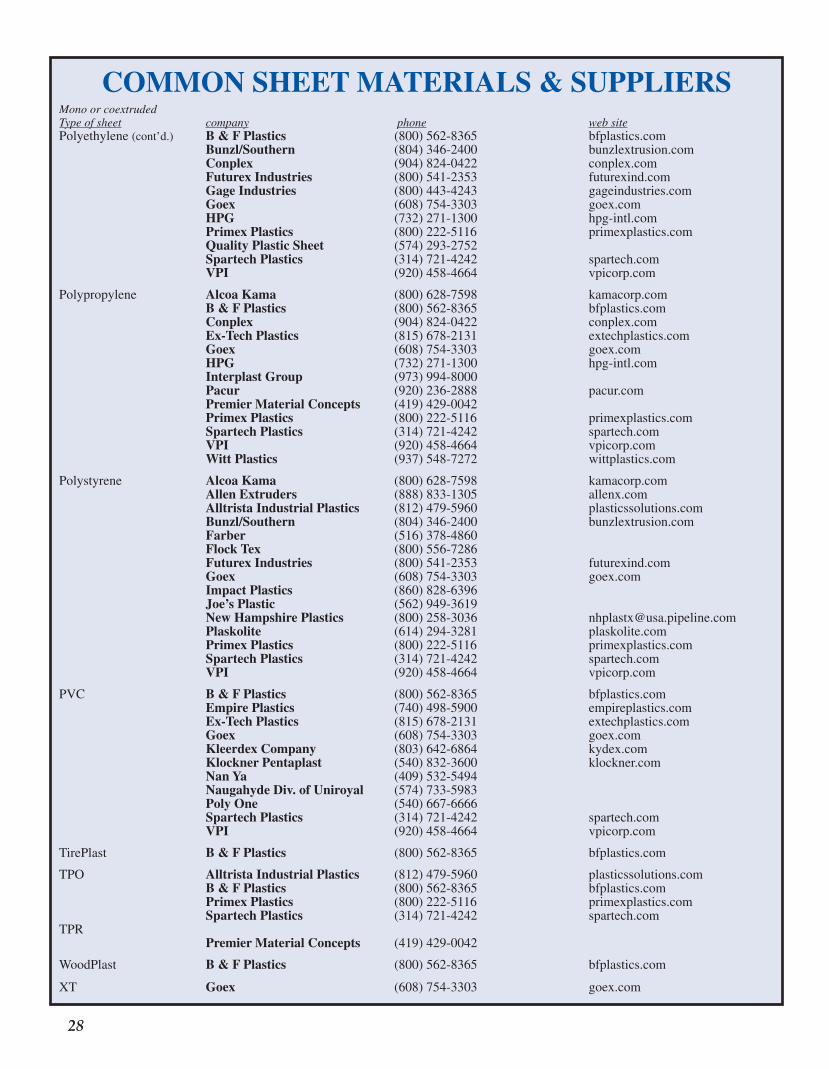
�� [This is one in a series of articles introducing general concepts in thermoforming.]
Mono or coextrudedType of sheet company phone web sitePolyethylene(cont’d.) B & F Plastics (800)562-8365 bfplastics.com Bunzl/Southern (804)346-2400 bunzlextrusion.com Conplex (904)824-0422 conplex.com Futurex Industries (800)541-2353 futurexind.com Gage Industries (800)443-4243 gageindustries.com Goex (608)754-3303 goex.com HPG (732)271-1300 hpg-intl.com Primex Plastics (800)222-5116 primexplastics.com Quality Plastic Sheet (574)293-2752 Spartech Plastics (314)721-4242 spartech.com VPI (920)458-4664 vpicorp.com
Polypropylene Alcoa Kama (800)628-7598 kamacorp.com B & F Plastics (800)562-8365 bfplastics.com Conplex (904)824-0422 conplex.com Ex-Tech Plastics (815)678-2131 extechplastics.com Goex (608)754-3303 goex.com HPG (732)271-1300 hpg-intl.com Interplast Group (973)994-8000 Pacur (920)236-2888 pacur.com Premier Material Concepts (419)429-0042 Primex Plastics (800)222-5116 primexplastics.com Spartech Plastics (314)721-4242 spartech.com VPI (920)458-4664 vpicorp.com Witt Plastics (937)548-7272 wittplastics.com
Polystyrene Alcoa Kama (800)628-7598 kamacorp.com Allen Extruders (888)833-1305 allenx.com Alltrista Industrial Plastics (812)479-5960 plasticssolutions.com Bunzl/Southern (804)346-2400 bunzlextrusion.com Farber (516)378-4860 Flock Tex (800)556-7286 Futurex Industries (800)541-2353 futurexind.com Goex (608)754-3303 goex.com Impact Plastics (860)828-6396 Joe’s Plastic (562)949-3619 New Hampshire Plastics (800)258-3036 [email protected] Plaskolite (614)294-3281 plaskolite.com Primex Plastics (800)222-5116 primexplastics.com Spartech Plastics (314)721-4242 spartech.com VPI (920)458-4664 vpicorp.com
PVC B & F Plastics (800)562-8365 bfplastics.com Empire Plastics (740)498-5900 empireplastics.com Ex-Tech Plastics (815)678-2131 extechplastics.com Goex (608)754-3303 goex.com Kleerdex Company (803)642-6864 kydex.com Klockner Pentaplast (540)832-3600 klockner.com Nan Ya (409)532-5494 Naugahyde Div. of Uniroyal (574)733-5983 Poly One (540)667-6666 Spartech Plastics (314)721-4242 spartech.com VPI (920)458-4664 vpicorp.com
TirePlast B & F Plastics (800)562-8365 bfplastics.com
TPO Alltrista Industrial Plastics (812)479-5960 plasticssolutions.com B & F Plastics (800)562-8365 bfplastics.com Primex Plastics (800)222-5116 primexplastics.com Spartech Plastics (314)721-4242 spartech.comTPR Premier Material Concepts (419)429-0042
WoodPlast B & F Plastics (800)562-8365 bfplastics.com
XT Goex (608)754-3303 goex.com
COMMON SHEET MATERIALS & SUPPLIERS
TF101 Insides 07.indd 28 9/25/07 8:55:43 AM

[This is one in a series of articles introducing general concepts in thermoforming.] ��
Recrystallization – What Does That Mean?1
In the last TF101, I mentioned recrys- tallization. In this tutorial, I will
explain what it is and why it is impor-tant in thermoforming.
Amorphous and Crystalline Plastics - A Brief Review In a very early lesson, we learned that there are two general classes of plastics used in thermoforming. Plastics such as polystyrene, ABS, polycarbonate and even rigid PVC are considered amorphous. That is, they are glassy-brittle at room temperature. When they are heated to a general temperature range called the glass transition temperature, they become rubbery. If we continue to heat them, they become less and less rubbery and more and more fluid-like. When we cool these polymers to their glass transition temperature, they imme-diately become glassy-brittle again. Amorphous polymers represent the majority of plastics thermoformed today. But as we learned in that early lesson, thermoformers are bent on forming crystalline - or more correctly, semicrystalline - polymers such as polyethylene, polypropylene and PET. For many years, polyethylene was the only semi-crystalline plastic that was widely thermoformed. PET is usually formed in the amorphous state (as APET). Special processes are needed to produce crystalline PET structures.
Melt Forming PE High-density PE has exceptional hot melt strength above its melt tem-perature of about 275°F (135°C). That’s
why the blow molder can extrude a tube of polyethylene, then capture it in a clamshell mold to make a bottle. Thermoformers also rely on the hot melt strength of it in sheet form. We heat the sheet above its melt tempera-ture just prior to forming it, as a melt. Polyethylenes are 50-80% crystalline and the sleek shape of the molecule allows very rapid crystallinity once the formed part is cooled below its melt temperature. As a result, HDPE is
the most successful semicrystalline polymer thermoformed.
Solid State Forming of PP Until recently, polypropylene recipes did not have sufficient hot strength to remain sheets in the thermoforming ovens. As a result, PP was thermoformed in the solid state. What this means is the PP sheet was (and is) heated to just below its melting temperature range, which is about 330°F (165°C) for h o m o p o l y m e r p o l y p ro p y l e n e (homoPP). PP becomes rubbery in a very narrow temperature range just below the melting temperature. There are two reasons for this rubberiness. First, the crystallinity of PP is about 50%, meaning that about half the PP is not locked in crystallites, but is instead in an amorphous state. The glass transition temperature of homoPP is about 15°F ( -10°C). So when homoPP sheet is at a forming temperature of about 320°F (160°C), say, the amorphous portion of the sheet is 305°F (170°C) above its Tg2. Secondly, imperfect crystallites tend to melt below the stated melt temperature. This means that more polymer is added to the amorphous side of the equation, making the sheet even more rubbery. With sufficient pressure then, we can squeeze, push and otherwise press PP
against the mold. Pressures of 50 to 100 psi have been used to do just this. So, what is the problem with solid state forming of PP? Really, nothing. It just requires higher forming pres-sures than what would be used for, say, PS. Oh, and the product is not water white but instead, about as translucent as the original sheet. This is because we don’t melt out the crystallites and the crystallites are of sufficient size to interfere with visible light (0.4 to 0.7 microns).
Melt Forming of PP Copolymerization of polyethylene in PP and now, short- and long-chain branching of PP has greatly improved PP hot strength. This lets us to ther-moform PP in the melt state, or the state where all the crystallites are fully melted. Copolymer PP or coPP usually melts around 310-320°F (155-160°C). But melt forming PP is not like melt forming polyethylene. We run into a very difficult problem. PP recrystallizes at a much slower rate than polyethylene. Even when coPP is cooling at 9°F/minute (5°C/min-ute)3, it recrystallizes around 210°F (100°C), or about 100°F (60°C) below its melt temperature. Small amounts of recrystallization rate enhancers such as sorbitols can increase the recrystal-lization temperature by about 20°F (10°C). While this may shorten the hold time on the mold, we still need to hold coPP on the mold longer than we might think. And more importantly, we need to be concerned about recrystallization that might continue long after we remove the formed coPP part from the mold surface. When the formed part isn’t constrained, different areas of the part can crystallize at different rates and to different crystallinity lev-els. Distortion, warping, cupping, and general mayhem can occur long after the part is formed. ■
Keywords: Recrystallization, solid state forming, melt forming, hot melt strength
1 Thermoforming 101 is designed to be a tutorial on the basic building blocks of the thermoforming industry. The first series of lessons concluded in TFQ 21:3, 2002. This is another in the second series of lessons that have as their objective to fill in the gaps from the first series of lessons.2 Compare this with PS at its thermoforming temperature of 350°F (175°C), or 140°F (75°C) above its Tg of 210°F (100°C).3 In practice, we would never cool PP this slowly. The test equipment used to mea-sure melting and recrystallizing tempera-tures operates at about this cooling rate.
A TECHNICAL ARTICLE 2004 VOLUME 23, #1
THERMOFORMING101
TF101 Insides 07.indd 29 9/25/07 8:55:44 AM

�0 [This is one in a series of articles introducing general concepts in thermoforming.]
A TECHNICAL ARTICLE 2004 VOLUME 23, #2
Alphabet Soup?It seems that plastics people never
tire of their alphabet soup – ABS, PTFE, PVC, PUR, and on and on. The soup continues when we consider evaluating the characteristics of plas-tics. In this short series, we consider a few of the letters in this soup.
Tg, Tm and DSC We’ve already discussed the first two. Tg is glass transition tempera-ture, or the temperature above which polymers become rubbery rather than glassy. Tg’s for polystyrene and acrylic are around 210°F (100°C). Tg for rigid PVC is around 185°F (85°C) but can be as low as -25°F (-30°C) when highly plasticized. The glass transi-tion temperature for nylon 6 is only 122°F (50°C). The Tg for polyethylene is around -125°F (-90°C) and that for homopolymer PP is 15°F (-10°C). You’ll recall that Tm is the melting temperature for crystalline polymers such as polyethylene, polypropylene and nylon. The melting temperature for HDPE is around 275°F (135°C). The melting temperature for homopoly-mers PP is 330°F (165°C), and that for nylon 6 is 430°F (220°C). One popular method for measuring Tg and Tm is with DSC. So, what is DSC? Differential scanning calorime-try. Consider heating a substance from room temperature, say, to a specific processing temperature. Let’s use wa-ter as an example. It takes exactly one calorie of energy to heat one gram of water one degree Centigrade. In Brit-ish units, it takes one British Thermal Unit of energy to heat one pound of water one degree Fahrenheit. This rule works until water reaches its boiling point of 212°F (100°C). At the boiling point, the temperature remains con-stant even though substantial energy is inputted to the water. If we were to compare the energy uptake of a substance that did not boil with that of water, we would see that the tem-perature of the non-boiling substance would continue to climb while that of water would remain constant until all the water had evaporated.
Conversely, if we cool water from room temperature to 32°F (0°C), it freezes. At the freezing point, the temperature remains constant even though substantial energy is removed from the water. Physical changes that take up energy with little or no temperature change, such as boiling or melting, are called endothermic changes. Physi-cal changes that give off energy with little or no temperature change, such as freezing or crystallizing, are called exothermic changes. We can build a device that compen-sates for these temperature differen-tials. The device uses a well-charac-terized substance as its reference. The substance to be tested is then heated at the same rate as the reference sub-stance. This is done by carefully con-trolling the energy ratio between the reference substance and the test sub-stance. Since the device is measuring calories or units of energy, it is called a calorimeter. Since the device measures the temperature difference between two substances as they heat, it is a scanning device. And since the device is looking at the difference between the two substances, it is a differential device. It we put this all together we see that the device is a differential scanning calorimeter, or DSC!
What Can We Learn From DSC? First, we must realize that the DSC can be used either in a heating mode or in a cooling mode. Samples are usually heated beginning at room temperature and they are usually heated at a fixed temperature rate such as 10°C/minute. The temperature range and energy requirements of transitions are the primary information gathered from heating DSCs. The most common transitions are the glass transition temperature and the melting tempera-ture, if any. Between transitions, the DSC pro-vides relative energy uptake by the test substance. This is directly related to that for water, as specific heat or
heat capacity. As we saw above, the amount of energy absorbed by water is 1 cal/gm°C or 1 Btu/lb°F. So its heat capacity is 1.0. It takes 100 cal/gm°C or 180 Btu/lb°F to heat water from 32°F to 212°F. We find that polystyrene has about 55% of the heat capacity of water and that for PVC has about 37% of that of water. PP has about 85% of the heat capacity of water and that for LDPE is about the same as that of water. Remember, now that these values are between transitions. DSC is important when trying to determine the extent of crystallization of a polymer. Consider the case for a 100% crystalline polymer that requires 100 cal/g to melt. If that polymer is cooled from the melt and DSC deter-mines that only 50 cal/g was liberated during recrystallization, it is safe to say that the polymer at room temperature is only 50% crystalline. In the last lesson, we learned that coPP melts around 155°C but recrys-tallizes at around 100°C. How did we know that? From DSC, of course. The DSC can teach us another as-pect to polymer characterization. As we increase the cooling rate for some crystalline polymers, we retard the temperature at which recrystalliza-tion begins. And we reduce the final level of crystallinity. How do we know this? Consider PET. It has a melting temperature of 510°F (265°C). If we cool PET very slowly, we find that it recrystallizes at around 250°C to about 40-45%. If we cool PET very rapidly, we find that there is no recrystalliza-tion region. PET remains amorphous at room temperature and beyond. DSC is therefore a tool for determining how rapidly a plastic crystallizes. ■
Keywords: glass transition, melting, recrystallization, calorimeter, endothermic, exothermic
THERMOFORMING101
TF101 Insides 07.indd 30 9/25/07 8:55:44 AM
[This is one in a series of articles introducing general concepts in thermoforming.] ��
A TECHNICAL ARTICLE 2004 VOLUME 23, #3
ABCs of Alphabet Soup?In our last lesson, we learned about
Tg, Tm, and DSC. These are impor-tant letters in our alphabet soup. In this lesson, we look at some new letters.
IR and FTIR IR means infrared and FTIR means Fourier-transform infrared. We usu-ally heat our plastic sheet with radiant heaters. These heaters emit infrared energy or IR. Infrared energy is part of the electromagnetic spectrum of en-ergy. The spectrum is usually defined in terms of the length of the emitting rays. And the length is usually given in microns. The length is identified by the symbol m. Radio waves are long-length waves, in the range of 107 to 1010 m. They reside near one end of the electromagnetic spectrum. Gamma rays are short-length waves, in the range of 10-4 to 10-7 m. They reside near the other end of the electromag-netic spectrum. In contrast, visible light has the wavelength range of 0.4 to 0.7 m. It is about in the middle of the electro-magnetic spectrum. Energy of shorter wavelengths, between 0.4 m and about 10-2 m, is ultraviolet energy. En-ergy of longer wavelengths, between 0.7 m and about 103 m, is called infrared energy. The infrared energy wavelength range is usually separated into near infrared energy, having wave-lengths between 0.7 m and about 2.5 m, and far infrared energy, having wavelengths between about 2.5 m and 103 m. Our thermoforming radiant heaters typically operate in the wavelength range of about 3.5 m to about 20 m or so. Or in the far infrared energy wave-length range. As you might expect, as the temperature of the radiating body increases, the peak wavelength shifts to short and shorter wavelengths. And as the radiating body temperature in-creases, the amount of energy emitted increases as well. For example, if your heater tempera-ture is 400°F (~200°C), the peak wave-length is 6.06 m, and the maximum amount of energy emitted at this wave-length is 2.94 units1. If you raise the
heater temperature to 600°F (~315°C), the peak wavelength is 4.92 m, and the maximum amount of energy emit-ted is 6.78 units. If you raise the heater temperature to, say, 900°F (~480°C), the peak wavelength is 3.83 m, and the maximum amount of energy emitted is 17.3 units. A couple of reference points, please! Certainly! The sun radiates at 12,000°F (~6500°C), its peak wavelength is 0.43 m, and the maximum amount of en-ergy it emits is nearly 120,000 units2! What about us! Because radiation is electromagnetic energy interchange, we radiate back to the sun at 98.6°F (37°C). Our peak wavelength is 9.35 m, and we emit about 0.52 units. We’re pretty feeble radiators! Okay, what about the sheet we’re trying to heat? Well, as the sheet heats, the amount of energy it radiates increases. Suppose the heater tempera-ture is 600°F. If the sheet reaches 400°F, it radiates a maximum of 2.94/6.78 = 43% of the energy it gets from the heater back to the heater! Really! Isn’t infrared energy fun? Okay, what is FTIR? Keep in mind that heaters emit and sheet absorbs far infrared energy. However, plas-tics do not absorb energy uniformly. The amount of energy absorbed at any given wavelength depends on the type of plastic being heated. Very few plastics uniformly absorb radiant energy only on their surfaces. When the radiant energy is not entirely ab-sorbed in the surface layer, some of it is transmitted into the plastic. If the sheet is thick enough, all the radiant energy that impinges the sheet surface is absorbed in the polymer. Plastics such as polyethylene are notoriously poor at absorbing energy on the sheet surfaces. Others, such as PVC, absorb a substantial portion of the incoming energy on the sheet surface. But how can we tell whether a sheet of plastic is absorbing most of its en-ergy on its surface or inside the sheet? That’s where FTIR comes in. For the moment, ignore the “FT” part of the alphabet soup. I take a thin film of my plastic, place it in an infrared or IR
scanner, and pass a monochromatic3 infrared beam through it. I measure the decrease in energy transmitted through the plastic film at that wavelength. I change the wavelength of the infrared beam and again measure the transmit-ted energy. If I scan the film with an infrared beam of wavelength range of 2 m, say, to 20 m, I will have covered the majority of the wavelength range of our heaters. Now, I double the film thickness and repeat the scan. This tells me how deep the infrared energy penetrates into my film. I continue doubling the film thick-ness until none of the infrared energy is transmitted through the film. The IR scanner is mostly used in an analytical polymer laboratory, where polymer chemists determine the gen-eral composition of the polymer and its additive packages. The various peaks that are generated at specific wavelengths are directly related to the molecular confirmation of the polymer. For example, the carbon-hydrogen bond is stretched at a frequency of about 3.5 m. As a result, all polymers containing C-H bonds absorb 100% of the 3.5 m infrared energy. PP does. PE does. PTFE doesn’t because it has no C-H bonds. What about the “FT” portion of FTIR? The polymer chemist obtains infrared scans of various recipes in or-der to compare the ingredients. These scans are then mathematically encoded so that the polymer chemist (or his computer software) can arithmetically subtract the infrared spectrum of the polymer, say, from the spectrum of the recipe. What’s left must be the additive package. By subtracting the infrared spectrum from a known additive pack-age, for example, the polymer chemist can determine the composition of any unknown in the recipe. The mathemati-cal encoding is called Fourier Transfor-mation or “FT.” And we’ve just put the “FT” back into FTIR. Do we care what the recipe of our plastic is? Not really. We just need to know how much infrared energy our plastic absorbs. So we just “piggy-back” on the polymer chemist’s FTIR device. ■Keywords: Infrared, far infrared, electromagnetic energy, wavelength, Fourier Transform
1 The units are kW/m2 - m.2 Think Clearwater Beach, Florida at 1400 hours on July Fourth!3 Monochromatic: Of or composed of radia-tion of only one wavelength.
THERMOFORMING101
TF101 Insides 07.indd 31 9/25/07 8:55:45 AM

�� [This is one in a series of articles introducing general concepts in thermoforming.]
A TECHNICAL ARTICLE 2004 VOLUME 23, #4
XYZs of Alphabet Soup?
This is the third in a series on plas- tics alphabet soup. So far, we’ve
tackled Tg and Tm. And we spent time with DSC and IR and FTIR. Are there more acronyms1 that we should know about? Sure. Lots. In this discourse, we look at four more – HDT, DTA, DMA, and DTMA.
What is HDT?
HDT stands for heat deflection tem-perature2. It is an ASTM test (D648) and an ISO test (75-1, 75-2)3. The test fo-cuses on the three-point deflection of a plastic bar of very specific dimensions4. The bar is placed in an oil bath. A dead weight is placed in the center5. The oil bath is heated at a very specific rate6. As the plastic increases in temperature, it softens. HDT is the temperature at which it sags a fixed amount7. This test, without ASTM or ISO numbers, is more than 60 years old. HDT is often used to sort or rank plastics. And it is often used for quality control. In thermoforming, it provides a crude, early estimate of the lower temperature for forming. Unfortunately, it is not a very good test. For example, it has no value for plastics that are relatively soft at room temperature, such as some plasticized PVCs and TPOs. The test yields a single data point that should not be used to predict long-term behavior. The test is often tricked by residual stress in the test specimen. And it is tricked if the polymer has very low
thermal conductivity or if the oil bath is not vigorously stirred. Here is another way the data can mislead. Consider HDT values for polycarbonate and nylon 6 for two loads:
Plastic HDT @ HDT @ 66 psi 264 psiPolycarbonate 290°F 275°FNylon 6 370°F 150°F
What is the real HDT value for nylon 6? And one more reason to avoid HDT values. Consider glass-reinforced poly-carbonate and nylon 6 HDT values: Plastic Unrein- Reinforced forced @ HDT @ 264 psi 264 psiPolycarbonate 275°F 295°FNylon 150°F 420°F
Again, what is the HDT of nylon 6? Nuff, said!
DTA, DMA, and DTMA. Are These the Same?
First, DTA. DTA stands for differen-tial thermal analysis. Remember our discussion on DSC, differential scan-ning calorimetry? Well, DTA uses the same equipment and the same analysis as that for DSC. The difference is that the data are interpreted differently for DTA. For example, DTA yields specific heat, or the amount of heat absorbed by the plastic as a function of tempera-ture. Time-dependent changes such as rate of crystallization are obtained by running the DSC/DTA at different heating (or cooling) rates. DMA is the acronym for differential mechanical analysis and DTMA is the acronym for differential thermal me-chanical analysis. The earliest device is described in ASTM D 2236. A review of various mechanical testing techniques is described in ASTM D 4065. In gen-
eral, a solid plastic test bar is subjected to torsional or flexural oscillation. Usually, if the device is operated at a fixed temperature and the frequency of oscillation is varied, the test is called DMA. If the device is operated at a fixed oscillation frequency and the temperature is varied, the test is called DTMA. There is an imperfect correlation between these two testing procedures. What is DMA/DTMA used for? If the plastic is elastic, its resistance matches that of the oscillating device. If the plastic is fluid or viscous, its resistance is out-of-phase with that of the oscillating device. As the tempera-ture or frequency is changed, device detects shifts from elastic to viscous or viscous to elastic character in the polymer. As a result, the data will yield the glass transition temperature of the polymer. More importantly, however, the test will show plastic resistance to applied load over a temperature range up to its melting temperature. This is important for thermoformers, since we are stretching the plastic while it is primarily in its rubbery solid state. For example, we can quickly assess the forming temperature range of the plastic. And within a given polymer family, we can determine which poly-mer recipe yields the broadest forming window. DMA/DTMA will probably be the subject for a TF 101 lesson. DMA/DTMA data obviate single-point values such as those obtained with HDT/DTUL devices. ■
Keywords: mechanical analysis, heat deflection, heat distortion, oscillation frequency
1 Acronym: a word formed from the initial letters of a multi-word name.2 HDT was originally called heat distortion temperature.3 Another acronym used for the ASTM test is DTUL, meaning deflection temperature under load.4 5 inches long by 1/2-inch thick by a width not to exceed 1/2-inch. ISO specifications are similar but in metric units.5 The weight is equivalent to either 66 or 264 lb/in2 fiber stress. ISO specifications are similar but in metric units.6 2 +/- 0.2°C/min.7 0.010 inches. ISO specifications are similar but in metric units.
THERMOFORMING101
TF101 Insides 07.indd 32 9/25/07 8:55:46 AM

[This is one in a series of articles introducing general concepts in thermoforming.] ��
Why is Part Design Important?
Throughout th is ser ies o f tutorials, we have assiduously1
avoided the issue of part design. And for good reasons. First and foremost, technologists – of which I am one – are normally not good designers. We tend to get hung up on the nuts-and-bolts of problem solving rather than the esthetics of the thing we’re making. And second, there really isn’t a good way of categorizing part design, particularly when there are so many applications and variants on the process. Having cited these caveats, per-haps it is time to review at least some of the generic aspects about thermoformed part design. We try to do this in the next series of lessons. And we begin by considering some of the limitations to the thermoform-ing process.
Can You Make the Part the Customer Wants at the Price He’ll Pay (and Still Make a Profit)? There are some fundamental rea-sons for not quoting on a job, even though it appears “doable” and the potential profit is substantial. Some of these are obvious, to wit:
• The parts are too large for the available equipment
• The parts are too small for the available equipment
• Too few parts are needed• Too many parts are needed
Others depend on the nature of the plastic needed for the job. Consider these limitations:
• The polymer cannot be ex-truded into sheet
• The polymer cannot be drawn to the requisite depth
• The polymer needs to be drawn to near its extensional limit
• The polymer cannot be reground or reprocessed economically
• The design requires high-per-formance plastics
• The design requires highly filled or reinforced plastics
Some depend on the match be-tween the part requirements and your forming abilities:
• The design requires complex forming techniques that you don’t have
• It is more exotic than your cur-rent skills
• The design accuracy is greater than your current abilities
• You cannot trim to the required accuracy
• Your workers do not have the skills to repeatedly form quality parts
• You do not have in-house ability to test product serviceability
• You cannot prototype to deter-mine part acceptability
And still others depend on the characteristics of the design, such as:
• The forces required to achieve the final shape are too high for the available equipment
• The design requires excessive web or trim
• Part tolerances, draft angles are unachievable in thermoform-ing
• Part design requires uniform wall thickness
• Part design requires stepped wall thicknesses
And finally, the coup de grace2 – Competitive processes are more competitive! This one is probably the most difficult design limita-tion, simply because companies using competitive processes are now recognizing the capabilities of thermoforming and now are either altering their technologies to com-pete more effectively or are deciding to enter the thermoforming field.
What Not To Do In most cases, we know the limita-tions of our equipment and ourselves. So we quote on parts we know we can mold. In some cases, however, the thrill of “taking a chance” is too much to pass by. That’s when the thin-gauge part must be molded diagonally with the mold ends ex-tending beyond the platen. Or when we try to “pressure form” in a press without a proper clamping system, hoping that the press won’t open un-til the part has completely form. Or when the depth of draw of the part is so great that we need to heat the sheet until it sags to the point where it drags across the tooling. Or when … Well, you get the idea.
So, What Lessons Will We Learn? In this series-within-a-series, we’ll take a look at some simple issues such as female or negative molding and male or positive forming. We’ll consider design aspects such as cor-ners and chamfers, vent hole loca-tions, and lip and edge formation. And surface texture, draft angles, and more. It should be fun. And maybe we’ll all learn something on the way. ■
Keywords: Design, formability, dimensional tolerance, draft angle
1 Assiduously: Unceasingly; persistently.2 Coup de grace: A decisive, finishing stroke.
A TECHNICAL ARTICLE 2005 VOLUME 24, #1
THERMOFORMING101
TF101 Insides 07.indd 33 9/25/07 8:55:47 AM

�� [This is one in a series of articles introducing general concepts in thermoforming.]
A TECHNICAL ARTICLE 2005 VOLUME 24, #2
Comparing Concept to Reality1
1 This is the second in a series that focuses on part design2 vis-à-vis, French for face-to-face, with the usual meaning being “as compared with” or “in relation to.”
We began our discussion of part design by reviewing why we
might not want to quote on a job. If we are serious about fabricating the customer’s concept, we need to understand the methodology in reducing a concept to reality.
Naiveté v. Experience Before we consider developing a hard cost for a given project, we need to ascertain the technical level the customer brings to the design. Most of us have dealt with customers of at least one of the following levels:
• Expert Customer. Fully cog-nizant of the advantages and limitations of thermoforming in general, conversant of the plastics characteristics, and having a complete under-standing in the myriad ways of fabricating his design, in particular.
• Experienced Customer. Has designed certain parts in ther-moforming in the past but is not up-to-date, vis-a vis2, newer processing techniques, mold materials, polymers, and so on.
• A Non-Thermoforming Techni-cal Customer. Has extensive experience in blow molding, rotational molding, or in-jection molding, but has no knowledge of the differences between these techniques and thermoforming.
• A Technically Naïve Customer. Knows little about plastics and nothing about thermoforming. Has always purchased his
plastic products to either mate with or package his non-plas-tic products.
• The Totally Naïve Customer. Has a great idea worked out on the back of a Burger King napkin, has no funding, no customer, and no idea how to reduce his idea to reality.
We all agree that it is very difficult to treat each of these in the same fashion. In other words, a checklist of things necessary to reconcile prior to quotation might be too technical for the naïve customer and an insult to the experienced one. Nevertheless, we should all keep in mind before every take-off and landing, the pilot and copilot are required to complete an extensive checklist, regardless of their years of experience and the number of times they had flown the specific airplane. So let’s take a look at a typical design checklist.
General Advantages and Limitations of Thermoforming We all know the advantages and limitations of our skills. But the customer may not. So tell him/her. Some advantages:
• Lower tooling costs• Quicker design-to-prototype
time• Quicker prototype-to-produc-
tion time• Relatively wide selection of
polymers, grades• Large surface area per unit
thickness• Economic production of a few
pieces (heavy gauge) or many, many pieces (thin gauge)
Some limitations:
• Non-uniform wall thickness• Single-surface molds • Hollow parts difficult• Sheet cost
• Extensive trimming, recycling needed
• Mostly neat plastics (few reinforced and highly filled plastics)
• Wide forming windows de-sired (needed)
The Material Issue We, along with the astute custom-er, need to discuss material choices in some detail. It is not enough for the customer to specify “general purpose polystyrene.” He/she needs to work with us to develop a list of property requirements. In other words, what are the elements of the environment in which the product must perform? Some examples are:
• Environmental temperatures (high and low)
• Corrosive/erosive conditions• Static/dynamic loading condi-
tions• Impact conditions• Surface quality• Product lifetime• Assembly restrictions (if any)
And we must all be aware that some of these conditions are com-pound. For example, the product may need to withstand dynamic loading at high temperature in a corrosive environment. And the customer must understand that not all grades of plastics that meet the desired criteria are available in sheet form. Before we can discuss design con-cepts with our customer, we need to review them ourselves. We’ll con-tinue this litany after our review. ■
Keywords: advantages, limitations, material choice, experienced customer, naïve customer
THERMOFORMING101
TF101 Insides 07.indd 34 9/25/07 8:55:48 AM

[This is one in a series of articles introducing general concepts in thermoforming.] ��
A TECHNICAL ARTICLE 2005 VOLUME 24, #3
Understanding How a Sheet Stretches1
1 This is the third in a series that focuses on part design.2 PC. Politically correct.3 We discuss draw ratio in the next les-son.4 By “positive surface,” we mean that sur-face that the customer considers to be the more important one. Usually the surface against the mold is considered the positive surface, but not always.5 Efficacious: Producing or capable of pro-ducing a desired effect.
We began our discussion of part design by reviewing why we
might not want to quote on a job. But let’s suppose that we did quote on the job. And we got it. Now what?
Forming into a Mold v. Forming onto a Mold In the not-so-politically-correct jar-gon of the day, if we form into a mold cavity, the mold is called a “female cavity.” A better PC2 phrase is “nega-tive mold.” If we form onto a mold, the mold is called a “male mold.” The proper PC phrase is “positive mold.” Is there a difference in forming “into” v. forming “onto”? Of course. Let’s consider for the moment, forming a very simple truncated cone. If we use a mold cavity, the sheet first drapes into the open cavity, then stretches into the cavity with the sheet progres-sively laying on the mold surface. Keep in mind that the sheet that con-tacts the mold surface usually doesn’t stretch any further. As a result, the sheet that is free of the mold becomes thinner and thinner as it is stretched to the bottom of the mold. The wall of the resulting part is thickest at the rim and thinnest at the bottom. The thin-nest region of the part is in the corner where the wall meets the bottom. We can show arithmetically that if the wall makes a 60-degree angle with the horizontal rim, the wall thickness decreases linearly from the rim to the corner. If the wall makes a 90-degree angle [think soup can], the wall thick-ness decreases exponentially. Now consider using a truncated cone male mold. The sheet first touch-es the mold at the bottom of the part being formed. As the mold pushes into
the sheet, the sheet stretches between the clamp and the bottom of the mold. If the sheet doesn’t touch the sides of the mold until the mold is completely immersed in the sheet, the sheet thick-ness is usually quite uniform. If the sheet progressively touches the sides of the mold as the mold is being pushed into the sheet, the wall of the resulting part will be thickest at the bottom and thinnest at the rim.
gauge thermoforming, forming up has advantages with female molds. Grav-ity helps when releasing parts from multi-cavity tooling. And the parts are properly oriented for in-line trimming. Having said that, keep in mind that it is easier to mechanically prestretch the sheet into female cavities if the molds are below the sheet. Although the mold weight may prevent mounting the mold over the sheet in heavy-gauge forming, there are some advantages here too. For ex-ample, when a male mold is mounted over the sheet plane, sheet sag acts to prestretch the sheet prior to the mold immersion. The sheet is formed down for most heavy-gauge forming into female molds. Again, sheet sag acts to prestretch the sheet prior to forming. And certainly, it is easier to activate and maintain mechanical plugs if they reside above the sheet rather than below.
Mating Parts It should be apparent that the part side against the mold maintains a more accurate dimension than the other side. The mold side is chosen when-ever the part is to mate with another dimensioned part. For example, for an integral-lid container to be liquid tight, the outside of one half must mate with the inside of the other. This may require that one half is formed into a female mold while the other is formed on a male tool.
An Observation When quoting on a job, it is always advisable to keep in mind the capabil-ity of your equipment to form the part in the most efficacious5 and least costly manner. If you can’t form up, don’t quote on a job that is best produced in this fashion. The more tortuous the path to perfect parts, the greater the degree of difficulty. And surely the greater the chance for quality is-sues. ■
Keywords: positive mold, male mold, negative mold, female mold, draw ratio, forming up, forming down, sag
THERMOFORMING101
Does it make a difference whether we form into a cavity or over a mold? If part performance is important, probably not, if the part draw ratio3 is very low [think picnic plate or aircraft engine cover]. As the draw ratio in-creases, however, the thinnest sections of the part begin to control the perfor-mance of the part. Several other factors can influence our decision, such as:
• Is it easier to prestretch the sheet when forming into a cavity or over a mold?
• Is it easier to machine a cavity or a male mold?
• Is the rim thickness important, as in the case of thin-gauge contain-ers?
• And does the customer need the inside or the outside of the part to be the positive surface4?
Usually – but not always – mechani-cal plugs are more effective in stretch-ing sheet into a cavity, female molds are easier to fabricate than male molds, and rim thickness is better controlled with female molds. We’ll revisit some of these factors later.
Forming “Up” v. Forming “Down” What does this mean? If the mold is placed above the sheet, the mold is immersed in the sheet and the part is formed up onto or into the tool. If the mold is placed below the sheet, the sheet sags into or onto the mold and the part is formed down onto or into the tool. Why is this an issue? In thin-
TF101 Insides 07.indd 35 9/25/07 8:55:49 AM
�� [This is one in a series of articles introducing general concepts in thermoforming.]
A TECHNICAL ARTICLE 2005 VOLUME 24, #4
Probably the first thing a novice hears in thermo-
forming after he/she learns to spell “thermoforming,” is the phrase, “Draw Ratio.” So, this lesson focuses on the concept of draw ratio.
Is There More Than One Definition? Unfortunately, yes. There are at least three definitions. Let’s define the common ones. Areal Draw Ratio, often given the symbol RA, is the ratio of the area of the part being formed to the area of the sheet needed to make the part. Although I promised not to use equations in our TF 101 lessons, some simple ones here won’t hurt all that much:
RA = AreaPart/AreaSheet
A simple example, please? Consider a cylinder one unit in diameter by one unit high. The area of the cylinder is (+/4) = 54. The area of the sheet used to form the cylinder is /4. Therefore the areal draw ratio, RA, is 5. As an interest-ing aside, the reciprocal of the areal draw ratio is the average reduced thickness of the formed part, being 1/5 = 0.20. In other words, the original sheet thick-ness has been reduced by 80%, on the average. Linear Draw Ratio, often given the symbol RL, is the ratio of the length of a line scribed
The Ubiquitous1 Draw Ratioon the part surface to the origi-nal length of the line. Again, in equation form:
RL = LinePart/LineSheet
For the same example, the length of the line on the cylinder is (1+1+1) = 3. The original length of the line is 1. Therefore, the linear draw ratio, RL, is 3. The linear draw ratio is akin to the way in which the plastic is stretched in a tensile test machine, Height-to-Diameter Ratio, often written as H:D, is the height of the cylinder (1), to the diameter of the cylinder (1). Or H:D = 1. H:D is used primarily for axisymmetric2 parts such as cones or cylinders, such as drink cups. In summary, for the cylinder described above, RA=5, RL = 3, and H:D = 1. So you see, there is no agreement between these definitions.
Are Draw Ratios of Use? Importance? So, which one do we use? Depends. First, we need to determine whether draw ratio is a useful concept. Let’s focus on areal draw ratio to determine its utility. As we have already learned, the reciprocal of RA is the av-erage reduced thickness. But where is this reduced thickness? Somewhere down the side of the formed part. In fact, there is probably a line around the periphery of the part where the part thickness is exactly the
average reduced thickness. So, what does this tell us about the uniformity of the part wall thickness? Or the degree of dif-ficulty in forming the part? Or whether webs are formed some-where in the part? Or what the plug needs to look like? Or …? Really, nothing. Having said that, areal draw ratio is perhaps the easiest concept to understand. Linear draw ratio, as noted, is often compared with extension lim-its determined from tensile testing equipment. And H:D is often used in Europe to describe formability of plastics for cup applications. At best, draw ratios represent bragging rights rather than in-formation about the degree of difficulty in forming the parts. Many formers will tell you that parts that have very small draw ratios are much more difficult to form reliably than parts with large draw ratios. And parts with many compartments are far more difficult to form than parts with single compartments, even when the draw ratios of the two types are identical. [See? Those equations didn’t hurt at all, now, did they?] ■
Keywords: Areal draw ratio, linear draw ratio, H:D
1 Ubiquitous: Being present everywhere at once.2 Axisymmetric: Having symmetry around an axis.
THERMOFORMING101
TF101 Insides 07.indd 36 9/25/07 8:55:49 AM

[This is one in a series of articles introducing general concepts in thermoforming.] ��
A TECHNICAL ARTICLE 2006 VOLUME 25, #1
Draft Angles
THERMOFORMING101
Some time ago, we discussed shrinkage and warpage. At that
time, we pointed out that plastic, like most other materials, increases in volume when heated and decreases in volume when cooled. And we said that to form the desired shape, the hot plastic is pushed against a cool mold surface. It follows that as the plastic cools, it shrinks. But the mold doesn’t change in dimension. If the mold is male or positive, or if even a portion of the mold is male or positive, the plastic will shrink onto the mold surface. And if the mold is not properly designed, we will have a devil of a time getting the part off it. Thus we face the subject of draft angles.
Draft Angles – Defined The best definition of a draft angle is the angle the mold wall makes with the vertical. If the mold wall is vertical, the draft angle is zero. Recall that most thermoforming molds are single-surfaced. That is, the sheet is pulled into or over a single mold surface. For draw-down into a female or negative mold, the sheet is constrained on its outer surface by the mold. As a result, when the sheet cools, it tends to shrink away from the mold surface. As a result, it is entirely feasible to thermoform into a female mold having zero draft angles. Most part designers prefer a slight draft angle, say 0° to 2°, “just in case.” The average is generally 1/2° to 1°. On the other hand, when the sheet is drawn over a male or positive mold, it is constrained on its inner surface by the mold. As a result, when the sheet cools, it tends to shrink onto
the mold surface. To release the part from the mold, it is necessary to provide a draft angle on the vertical mold surfaces. The amount of draft depends strongly on the volumetric change in the polymer. If the polymer is amorphous – PS, PVC, PC – the draft angle may be no more than 2° to 3°. If the polymer is crystalline – PE, PE – the draft angle may be in excess of 5°. The average is generally 4° but the designer must be alert to effects of temperature variation and recrystallization rates. A textured surface requires an increase in draft angle. It is recommended that the draft angle be increased at least 1° for every 0.2 mils [0.0002 in or 5 microns] in texture depth. Keep in mind that increasing applied pressure, sheet temperature, and mold temperature will result in greater penetration of the sheet into the texture.
What About Parts With Male and Female Components? Multiple-compartment trays and pallets1 can pose series drafting issues. Consider a female cavity bordered by two male segments. The sheet will attempt to shrink away from the female mold surface but onto the male segments. Excessive draft on the male segments may allow the sheet to release from the female mold surface before the sheet has replicated the mold surface. On the other hand, inadequate draft on the male segments may allow the sheet to satisfactorily form the female mold surface, but the sheet may “lock” onto the male segments. The problem is exacerbated2 when molding compartment trays where the male portions are interrupted. Essentially interrupted walls in the molded part. In addition to the shrinkage issues, interrupted male
segments may also be sources of internal webbing3.
How Serious is the Draft Problem? The draft angle can lead to serious dimensional changes in the formed part. Consider a simple example, a 10-inch male mold. The vertical wall is 1 inch wide at the top. Consider a draft angle of 5°. The width at the bottom of the vertical wall is determined as follows: The increased width on one side is 10 x tan 5° = 0.875 in. The total width at the bottom is then 1 + 2 x 0.875 = 2.75 in. This is a substantial dimensional change in the thickness of the vertical wall.
When is the Draft Angle Not a Draft Angle at All?
When it is used for something else. The classic example is the drink cup. The sidewalls are tapered as much as 20° for stacking purposes, not shrinkage. In multi-compart-ment parts, care must be taken in the design to accommodate both the draft angle required for shrinkage and the necessary stacking taper. Stacking lugs, stand-offs, or rings are often designed into complex parts, simply because it is not always possible to predict the exact local shrinkage. ■
Keywords: draft angle, taper, shrinkage
1 These parts are sometimes called an-drogynous, meaning that they have both female and male characteristics.2 Exacerbate: To aggravate.3 Webbing will be discussed in a later lesson.
TF101 Insides 07.indd 37 9/25/07 8:55:50 AM
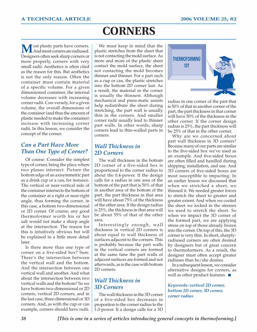
�� [This is one in a series of articles introducing general concepts in thermoforming.]
THERMOFORMING101
A TECHNICAL ARTICLE 2006 VOLUME 25, #2
CORNERS
Most plastic parts have corners. And most corners are radiused.
Designers often seek sharp corners or more properly, corners with very small radii. Aesthetics is often cited as the reason for this. But aesthetics is not the only reason. Often the container must contain material of a specific volume. For a given dimensioned container, the internal volume decreases with increasing corner radii. Con-versely, for a given volume, the overall dimensions of the container (and thus the amount of plastic needed to make the container) increase with increasing corner radii. In this lesson, we consider the concept of the corner.
Can a Part Have More Than One Type of Corner? Of course. Consider the simplest type of corner, being the place where two planes intersect. Picture the bottom edge of an axisymmetric part as a drink cup or a can, for instance. The vertical or near-vertical side of the container intersects the bottom of the container at a right or near-right angle, thus forming the corner, in this case, a bottom two-dimensional or 2D corner. Of course, any good thermoformer worth his or her salt would not make a sharp angle at the intersection. The reason for this is intuitively obvious but will be explained in a little more detail later. Is there more than one type of corner on a five-sided box? Sure. There’s the intersection between the vertical wall and the bottom. And the intersection between one vertical wall and another. And what about the intersection between two vertical walls and the bottom? So we have bottom two-dimensional or 2D corners, vertical 2D corners, and in the last case, three-dimensional or 3D corners. And, as with the cup or can example, corners should have radii.
We must keep in mind that the plastic stretches from the sheet that is not contacting the mold surface. As more and more of the plastic sheet contact the mold surface, the sheet not contacting the mold becomes thinner and thinner. For a part such as a cup or can, the plastic stretches into the bottom 2D corner last. As a result, the material in the corner is usually the thinnest. Although mechanical and pneu-matic assists help redistribute the sheet during stretching, the part wall is usually thin in the corners. And smaller corner radii usually lead to thinner part walls. In other words, sharp corners lead to thin-walled parts in corners.
Wall Thickness in �D Corners The wall thickness in the bottom 2D corner of a five-sided box is proportional to the corner radius to about the 0.4-power. If the design calls for a radius in one area of the bottom of the part that is 50% of that in another area of the bottom of the part, the part thickness in that area will have about 75% of the thickness of the other area. If the design radius is 25%, the thickness in that area will be about 55% of that of the other area. Interest ingly enough, wal l thickness in vertical 2D corners is about equal to wall thickness of surfaces adjacent to the corners. This is probably because the part walls in the vertical corners are formed at the same time the part walls of adjacent surfaces are formed and not afterwards, as is the case with bottom 2D corners.
Wall Thickness in �D Corners The wall thickness in the 3D corner of a five-sided box decreases in proportion to the corner radius to the 1.0-power. If a design calls for a 3D
radius in one corner of the part that is 50% of that in another corner of the part, the part thickness in that corner will have 50% of the thickness in the other corner. If the corner design radius is 25%, the part thickness will be 25% of that in the other corner. Why are we concerned about part wall thickness in 3D corners? Because many of our parts are similar to the five-sided box we’ve used as an example. And five-sided boxes are often filled and handled during shipping, installation, and use. And 3D corners of five-sided boxes are most susceptible to impacting. In an earlier lesson we discussed that when we stretched a sheet, we thinned it. We needed greater forces to stretch the sheet to greater and greater extent. And when we cooled the sheet we locked in the stresses we used to stretch the sheet. So when we impact the 3D corner of the formed part, we are applying stress on top of those already frozen into the corner. On top of this, the 3D corner is very thin. In short, sharply-radiused corners are often desired by designers but of great concern to thermoformers. As a result, the designer must often accept greater radiuses than he/she desires. In a subsequent lesson, we consider alternative designs for corners, as well as other product features. ■
Keywords: vertical �D corner, bottom �D corner, �D corner, corner radius
TF101 Insides 07.indd 38 9/25/07 8:55:51 AM
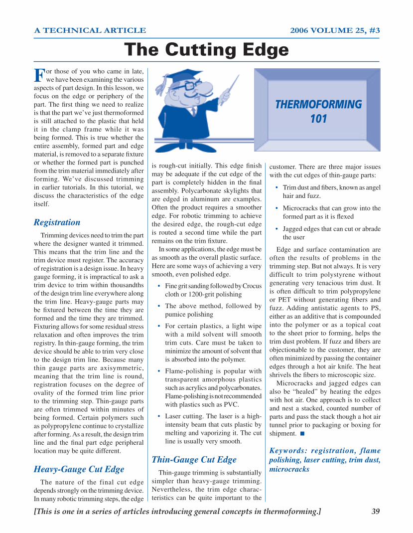
[This is one in a series of articles introducing general concepts in thermoforming.] ��
A TECHNICAL ARTICLE 2006 VOLUME 25, #3
The Cutting Edge
THERMOFORMING101
For thoseofyouwhocame in late,wehavebeenexaminingthevarious
aspectsofpartdesign.Inthislesson,wefocus on the edge or periphery of thepart.Thefirst thingweneedtorealizeisthatthepartwe’vejustthermoformedisstillattached to theplastic thatheldit in the clamp frame while it wasbeingformed.Thisis truewhethertheentire assembly, formedpart andedgematerial,isremovedtoaseparatefixtureorwhethertheformedpart ispunchedfromthetrimmaterialimmediatelyafterforming. We’ve discussed trimmingin earlier tutorials. In this tutorial, wediscuss the characteristics of the edgeitself.
Registration Trimmingdevicesneedtotrimthepartwherethedesignerwantedit trimmed.This means that the trim line and thetrimdevicemustregister.Theaccuracyofregistrationisadesignissue.Inheavygaugeforming,itisimpracticaltoaskatrimdevice to trimwithin thousandthsofthedesigntrimlineeverywherealongthe trim line. Heavy-gauge parts maybe fixtured between the time they areformedandthetimetheyaretrimmed.Fixturingallowsforsomeresidualstressrelaxationandoftenimprovesthetrimregistry.Inthin-gaugeforming,thetrimdeviceshouldbeabletotrimverycloseto thedesign trim line.Becausemanythin gauge parts are axisymmetric,meaning that the trim line is round,registration focuses on the degree ofovality of the formed trim line priortothetrimmingstep.Thin-gaugepartsare often trimmed within minutes ofbeing formed. Certain polymers suchaspolypropylenecontinuetocrystallizeafterforming.Asaresult,thedesigntrimline and the final part edge peripherallocationmaybequitedifferent.
Heavy-Gauge Cut Edge The nature of the final cut edgedependsstronglyonthetrimmingdevice.Inmanyrobotictrimmingsteps,theedge
is rough-cut initially.This edge finishmaybeadequateifthecutedgeofthepart is completely hidden in the finalassembly.Polycarbonateskylights thatare edged in aluminum are examples.Often theproduct requires a smootheredge. For robotic trimming to achievethe desired edge, the rough-cut edgeis routed a second timewhile thepartremainsonthetrimfixture. Insomeapplications,theedgemustbeassmoothastheoverallplasticsurface.Herearesomewaysofachievingaverysmooth,evenpolishededge.
• FinegritsandingfollowedbyCrocusclothor1200-gritpolishing
• The above method, followed bypumicepolishing
• For certain plastics, a light wipewith a mild solvent will smoothtrim cuts. Care must be taken tominimizetheamountofsolventthatisabsorbedintothepolymer.
• Flame-polishing is popular withtransparent amorphous plasticssuchasacrylicsandpolycarbonates.Flame-polishingisnotrecommendedwithplasticssuchasPVC.
• Lasercutting.Thelaserisahigh-intensitybeamthatcutsplasticbymeltingandvaporizingit.Thecutlineisusuallyverysmooth.
Thin-Gauge Cut Edge Thin-gaugetrimmingissubstantiallysimpler than heavy-gauge trimming.Nevertheless, the trim edge charac-teristics can be quite important to the
customer.There are three major issueswiththecutedgesofthin-gaugeparts:
• Trimdustandfibers,knownasangelhairandfuzz.
• Microcracksthatcangrowintotheformedpartasitisflexed
• Jaggededgesthatcancutorabradetheuser
Edge and surface contamination areoften the results of problems in thetrimmingstep.Butnotalways.Itisverydifficult to trim polystyrene withoutgenerating very tenacious trim dust. Itis often difficult to trim polypropyleneor PET without generating fibers andfuzz.Adding antistatic agents to PS,eitherasanadditivethatiscompoundedinto the polymer or as a topical coatto thesheetprior toforming,helps thetrimdustproblem.Iffuzzandfibersareobjectionable to thecustomer, theyareoftenminimizedbypassingthecontaineredgesthroughahotairknife.Theheatshrivelsthefiberstomicroscopicsize. Microcracks and jagged edges canalso be “healed” by heating the edgeswithhotair.Oneapproachistocollectandnest a stacked, countednumberofpartsandpassthestackthoughahotairtunnelpriortopackagingorboxingforshipment.■
Keywords: registration, flame polishing, laser cutting, trim dust, microcracks
TF101 Insides 07.indd 39 9/25/07 8:55:51 AM

�0 [This is one in a series of articles introducing general concepts in thermoforming.]
A TECHNICAL ARTICLE 2006 VOLUME 25, #4
The Rim
So, we know about draft angles and corners and wall thickness
variation and on and on. But what about the rim? You know, the region of the formed part that forms the periphery of the part. This lesson focuses on some of the important issues dealing with the rim. In the next lesson, we’ll look at the characteristics of the trimmed edge itself.
Does the Rim Have a Function in the Part? Other than just being the edge of the part, let’s say. In thin-gauge forming of axisymmetric parts such as cups, the trimmed-out rim is usually manipulated in a post-molding operation known are rim-rolling. Here, the cup is rotated along its axis as the rim is heated and softened. The rotating action forces the soften rim against a shaping ring that effectively rolls the rim into an annulus. The rolled rim provides great stiffness to an otherwise flimsy thin-walled container. Staying with thin-gauge products for a moment, the rim design for lidded containers often requires interlocks and detents that must be quite precise. In certain instances, the container rim may include denesting features that allow stacked containers to be readily separated by the customer. What about the rim on a heavy-gauge part? Often the rim is the finished edge of the part. The rim may be very simple, such as the trimmed end of a flat surface. Or it may be very complex, with radii,
portion of the part. And keep in mind that, without plug assist, parts really thin rapidly when vacuum- or pressure-drawn into parallel-walled mold sections.
What About Texture? Whenever you draw textured sheet, the texture flattens. In grained sheet, the effect is called “grain wash.” The typical rule of thumb is that texture flattening is acceptable if the local draw ratio is less than about two or the local thickness is more than half the original sheet thickness. The real problem occurs in the rim area where the sheet is often drawn into sharp corner radii. One design method is to chamfer the rim. A second is to facet the surface design. A third is to use a series of steps. In each of these cases, the objective is to trick the eye into seeing local architecture rather than texture. The alternative to drawing textured sheet is to texture the mold. However, as any mold maker will tell you, it is very difficult to build uniform texture into very sharply radiused corners. You should never fall into the habit of leaving rim design to the end of product design. ■
Keywords: rolled rim, moat, dam, hidden trim line, textured sheet
This is the last TF 101 column written by Throne. The new TFQ editorial staff will de-termine whether the column will continue.
THERMOFORMING101
chamfers, and ridges. The rim may be designed to fit into or over another part, Or it may be trimmed to accept secondary assembly features. The part design may require the tr im l ine to be “hidden,” so that the rim is U-shaped with appropriate radii or chamfers.
Can We Get the Formed Part Off the Mold? Before we contemplate this question in detail, remember that thermoformed parts shrink as they cool. So they shrink away from the sides of a female or negative mold cavity and onto the sides of a male or positive mold cavity. If we build a simple cup mold, for example, and design the rim so that the plastic is formed over a ring at the mold top, we need to provide adequate draft to get the thing off the mold. In other words, the rim will not have right-angled sides. Does this affect the design? By the way, this design is often called a “dam” design. This design minimizes excess plastic from being drawn over the edge of the mold and into the mold cavity. Frequently a trim line concentric to the dam will also be molded in. This is often called a “moat.” We discussed the hidden trim line a minute ago. How are we going to get the part off the mold? Flip-up sections? Removable sections? It is very difficult to get moving mold sections to seat without a gap between mating parts. As a result, we may wind up with a “witness line” right at the most cosmetic
TF101 Insides 07.indd 40 9/25/07 8:55:52 AM

�� [This is one in a series of articles introducing general concepts in thermoforming.]
A TECHNICAL ARTICLE 2007 VOLUME 26, #1
Process – Cycle Time (Editor’s Note: This is the first Thermoforming 101 article written by your new technical editor. Dr. Throne wrote 34 articles that date back to 1998, Volume 17, Number 3. He had originally intended to write a series of 18 general interest articles but the 101 series has become a mainstay of the Quarterly. The year-end booklet that contains every 101 article to date is a great reference source for thermoforming practitioners. This technical editor has every intention of maintaining the series and the booklet which is becoming the perfect reading material for people entering the industry or seasoned personnel who need help on a specific problem. Jim wrote 4 articles last year that dealt with part design. I hope he will forgive me for not continuing with the “Trimmed Edge” topic he suggested for this lesson. I will deal with this topic when we take a closer look at the subject of “Die-Cutting.” This Thermoforming 101 article deals with a subject about which we should all be more diligent. Foreign competition has forced us to maximize efficiency and become more competitive. So let us review the basic factors that determine cycle time.)
General Assumptions We all should be aware that if we let theoperator determine when a machine cycles,our production rate will suffer. Runningthermoformingmachinesonmanualmode isnecessaryforsetupandofcourseifallyouhaveisasimpleshuttlemachinewithrudimentarycontrolsyouhavenootherchoice.Solet’sjustdealwith thermoforminginautomaticmode.We will only deal with the forming part ofthe process.Trimming of heavy gauge partsisanothertopic.Alsoforthispurposewewillassume that when thinking roll-fed, we areusingamachinewithin-linedie-cutting.
The Basic Concept Ifwetakeallthesegmentsoftherotaryorin-linethermoformingprocess:heating.indexingthesheet,closingthepress,formingthepart,coolingthepart,openingthepress,trimmingand stacking (if in-line), the cycle time isdictatedsolelybytheslowestsegmentoftheprocess.Mostpeoplelookingatourprocessforthefirsttimewillsayithastobetheheatingsegmentthatistheslowestpartoftheprocess.Thisisnotnecessarilyso.
Roll-Fed Itisespeciallynotsowithroll-fedmachinesthatusuallyaredesignedtohave4indexesintheovens.Forexampleifthemaximummoldsize in the index direction is 36".The ovenlengthwillberoughly4times36"or12feetlong.Soifyouarerunning .020PVCwhichwouldnormallybeintheovenfor20secondstogetup to forming temperature,yourcycletime, based on a 4 index oven, is 5 seconds(20dividedby4)or12cyclesperminute.Thisis not bad for running smaller and medium
sizequantitiesbutitcanbealotbetter.Iwillexplainlater.
Sheet-Fed OK, so what about heavy-gauge, sheet-fed forming?The sameprinciple applies. InNorthAmericathemachinerymanufacturersrecognizedearlyonthattheymustdosomethingaboutthelengthoftimeittakestoheatthesheetevenlyandthoroughly.Sothe4stationrotarymachinewasdesignedwhichcutheatingtimedramaticallybyusing2heaterbanksthroughwhichthesheettravelsonitswaytothemold.Sowhynotbuilda5stationrotarywith3heaterbanksandreallycutheatingtime?Theansweris,therewouldbenopointunlessthepartcouldbeformedandcooledinatimelessthanonethird theheating time. Infact thecoolingofsomematerials issodifficult thatoneheaterbankona4stationwouldhavetobeshutoffor set at a lower temperature to allow timeforpropercooling.Soifwecandothingstospeed up the heating of the sheet, what canwedotocoolthepartquicker?Thisiswhereitgetstricky.
The Forming Segment of the Cycle Onroll-fedmachines,unlessyouaredealingwithsuperfastlines,youcanforgetaboutthetrimmingandstackingsegmentsofthecyclewhenlookingforwhatisslowingyoudown.Concentrateontheformingsegmentfromthetimethesheetleavestheheaterstothetimetheformedpartleavestheformstation.Let’sbreakdowntheactionsthattakeplace. Index speed is the speed that the sheettravels from the heaters to the form station.Roll-fedpinchainscantravelupto95inchesper second.A rotary turntable moves a lotslower. On both roll-fed and sheet-fed linesthestoppingandstartingactionscanbecometooviolentiftheindexspeedistoofastwhichmaycausethehotsheettomoveasthemoldclosesonit.Movethesheetasfastaspossiblebutmakesurethatthedrapeisstationarywhenthemoldcloses. Shut height or platen travelisthedistancethe form platens must travel from the openposition to theclosedposition.All toooftenset-uppeoplewillnottakethetimetoreducetheshutheighttooptimumlevels.Ihaveseenaroll-fedjobrunningveryshallowpillblisterswith a female tool on the bottom and theplugsonthetopshowing3inchesofdaylightbetweentheplugsandthesheetlinebecausetheoperatordidnotlowertheshutheightofthetoppress.Thisaddedatleast1secondtothecycletimeandovera30hourrunat15cyclesperminuteaddedover2hoursofunnecessarylaborandmachinetime.Ifyoudon’thaveshutheightadjustmentonyourformpresstheonlywaytodothisistoaddbuildupsbehindthe
tooling. Fortunately the new machines haveelectric presses which make setting the shutheightsomucheasier. Press speedaffectsthelengthofthecycletimebutsometimesitisnecessarytoslowthepressclosing speed toaccommodateplugorassistaction.Ifyouarehavingdifficultywithde-moldingyoumayneedtoslowtheopeningspeed. Other than these conditions, you canmove the platens as fast as you want.Thirdmotion tooling or independent plug controlwith individual cavity clamping can greatlyimprovecycletimebutthisisgettingbeyondthescopeofa101article. Cooling time isby far themost importantfactorinachievingafastcycletime.Inmyveryearlydaysofthermoformingwetriedrunninganepoxymoldonamoderninlinemachine.Evenwithawatercooledbaseunderthemoldthe best we could do is 2 cycles per minutesimplybecause themoldnevergotachanceto cool down. Using an aluminum mold ona water cooled base allows you to run mostjobsatreasonablespeedsaslongastheheight(or depth if it’s a female) of the mold is nomorethansay2inches.Toachievemaximumefficiency and reduce cooling time themoldmust be kept at the target temperature asspecifiedbythematerialsupplier.Hotmaterialat350degreesFhittingthemetalmoldrequiresaveryefficientcoolingsystemtomaintainthatmoldtemperaturethatmayhavetorunat200degrees F constantly to run fast cycles.Theonlywaytodothisistoruncoolinglinesinthemolditselfusuallynomorethan2"to3"apartdependingonthesizeandconfigurationofthemold.Cast-inlinesarethenormforaluminumcastmoldsandmachinedinlinesarethenormformachinedaluminummolds. Coolingtimeonsheet-fedrotarymachinesrunningthickHDPEcanbeimprovedbyusingexternal fans,watermistorcoldairdirectedonto the part but care must be taken not toform in stresses.A well built water cooledmoldisstillnecessaryforthemostsignificantimprovementincycletime. Sohowdosomeroll-fedthermoformersget50,000partsperhour?Thiswillbethesubjectof technical articles in the future. It’s not asubjectforthe101seriesbuthereisahint:thirdmotiontools,cavityclamping,pre-heatersandgreatcoolinginthemolds. Cycle time is just one way to make ouroperations leanandmorecompetitive.OtherwayswillbediscussedinfutureThermoforming101articles.■
THERMOFORMING101
TF101 Insides 07.indd 41 9/25/07 8:55:53 AM
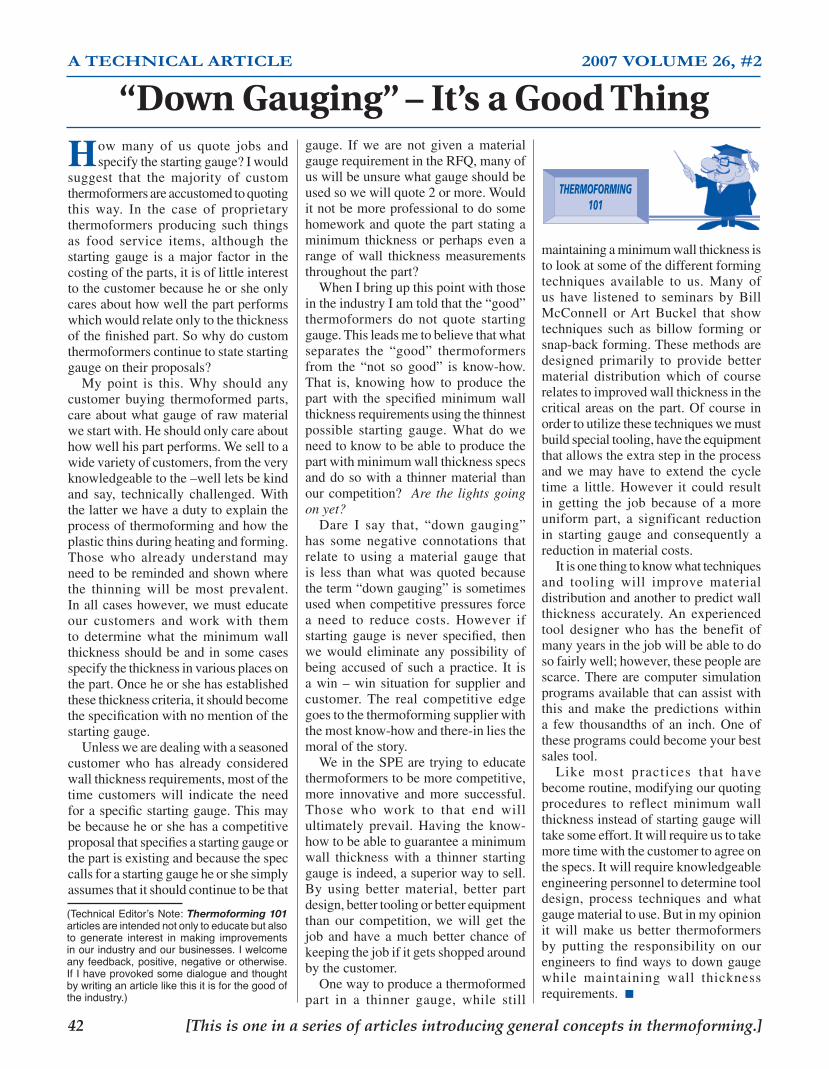
�� [This is one in a series of articles introducing general concepts in thermoforming.]
A TECHNICAL ARTICLE 2007 VOLUME 26, #2
THERMOFORMING101
gauge. If we are not given a materialgaugerequirementintheRFQ,manyofuswillbeunsurewhatgaugeshouldbeusedsowewillquote2ormore.Woulditnotbemoreprofessionaltodosomehomeworkandquotethepartstatingaminimum thickness or perhaps even arange of wall thickness measurementsthroughoutthepart? WhenIbringupthispointwiththoseintheindustryIamtoldthatthe“good”thermoformers do not quote startinggauge.Thisleadsmetobelievethatwhatseparates the “good” thermoformersfrom the “not so good” is know-how.That is, knowing how to produce thepart with the specified minimum wallthicknessrequirementsusingthethinnestpossible starting gauge. What do weneedtoknowtobeabletoproducethepartwithminimumwallthicknessspecsanddosowitha thinnermaterial thanourcompetition? Are the lights going on yet? Dare I say that, “down gauging”has some negative connotations thatrelate to using a material gauge thatis less than what was quoted becausetheterm“downgauging”issometimesusedwhencompetitivepressuresforcea need to reduce costs. However ifstarting gauge is never specified, thenwe would eliminate any possibility ofbeing accusedof such apractice. It isawin–win situation for supplier andcustomer. The real competitive edgegoestothethermoformingsupplierwiththemostknow-howandthere-inliesthemoralofthestory. WeintheSPEaretryingtoeducatethermoformerstobemorecompetitive,more innovative and more successful.Those who work to that end willultimately prevail. Having the know-howtobeabletoguaranteeaminimumwall thickness with a thinner startinggaugeisindeed,asuperiorwaytosell.By using better material, better partdesign,bettertoolingorbetterequipmentthan our competition, we will get thejob andhave amuchbetter chance ofkeepingthejobifitgetsshoppedaroundbythecustomer. Onewaytoproduceathermoformedpart in a thinner gauge, while still
maintainingaminimumwallthicknessistolookatsomeofthedifferentformingtechniques available to us. Many ofus have listened to seminars by BillMcConnell orArt Buckel that showtechniques such as billow forming orsnap-backforming.Thesemethodsaredesigned primarily to provide bettermaterial distribution which of courserelatestoimprovedwallthicknessinthecriticalareason thepart.Ofcourse inordertoutilizethesetechniqueswemustbuildspecialtooling,havetheequipmentthatallowstheextrastepintheprocessand we may have to extend the cycletime a little. However it could resultin getting the job because of a moreuniform part, a significant reductionin starting gauge and consequently areductioninmaterialcosts. Itisonethingtoknowwhattechniquesand tooling will improve materialdistributionandanothertopredictwallthickness accurately.An experiencedtool designer who has the benefit ofmanyyearsinthejobwillbeabletodosofairlywell;however,thesepeoplearescarce.Therearecomputer simulationprogramsavailablethatcanassistwiththis and make the predictions withina few thousandths of an inch. One oftheseprogramscouldbecomeyourbestsalestool. Like most practices that havebecomeroutine,modifyingourquotingprocedures to reflect minimum wallthicknessinsteadofstartinggaugewilltakesomeeffort.Itwillrequireustotakemoretimewiththecustomertoagreeonthespecs.Itwillrequireknowledgeableengineeringpersonneltodeterminetooldesign, process techniques and whatgaugematerialtouse.Butinmyopinionit will make us better thermoformersby putting the responsibility on ourengineers tofindways todowngaugewhile maintaining wall thicknessrequirements.■
(Technical Editor’s Note: Thermoforming 101 articles are intended not only to educate but also to generate interest in making improvements in our industry and our businesses. I welcome any feedback, positive, negative or otherwise. If I have provoked some dialogue and thought by writing an article like this it is for the good of the industry.)
“Down Gauging” – It’s a Good Thing
How many of us quote jobs andspecifythestartinggauge?Iwould
suggest that the majority of customthermoformersareaccustomedtoquotingthis way. In the case of proprietarythermoformers producing such thingsas food service items, although thestartinggauge is amajor factor in thecostingoftheparts,itisoflittleinteresttothecustomerbecauseheorsheonlycaresabouthowwellthepartperformswhichwouldrelateonlytothethicknessofthefinishedpart.Sowhydocustomthermoformerscontinuetostatestartinggaugeontheirproposals? My point is this. Why should anycustomer buying thermoformed parts,careaboutwhatgaugeofrawmaterialwestartwith.Heshouldonlycareabouthowwellhispartperforms.Weselltoawidevarietyofcustomers,fromtheveryknowledgeabletothe–wellletsbekindand say, technically challenged.Withthelatterwehaveadutytoexplaintheprocessofthermoformingandhowtheplasticthinsduringheatingandforming.Those who already understand mayneedtoberemindedandshownwherethe thinning will be most prevalent.Inallcaseshowever,wemusteducateour customers and work with themto determine what the minimum wallthicknessshouldbeandinsomecasesspecifythethicknessinvariousplacesonthepart.Onceheorshehasestablishedthesethicknesscriteria,itshouldbecomethespecificationwithnomentionofthestartinggauge. Unlesswearedealingwithaseasonedcustomer who has already consideredwallthicknessrequirements,mostofthetime customers will indicate the needforaspecificstartinggauge.Thismaybebecauseheorshehasacompetitiveproposalthatspecifiesastartinggaugeorthepartisexistingandbecausethespeccallsforastartinggaugeheorshesimplyassumesthatitshouldcontinuetobethat
TF101 Insides 07.indd 42 9/25/07 8:55:54 AM

�� [This is one in a series of articles introducing general concepts in thermoforming.]
The ImpossibleDraw Ratio
A Technical Article – 2006 Volume 26, #3➤ By Barry Shepherd
➤ Thermoforming 101
(Technical Editor’s Note: Looking back over the last 9 years at 36 Thermoforming 101 articles, which are all presented in our annu-ally updated booklet, it is the most comprehensive collection of basic technical information one could find on our process. For this issue I have chosen to talk about a subject that my predecessor Jim Throne wrote about in 2000 and 2001 – pre-stretching the sheet. But this time I want to discuss what type of pre-stretching should be used in a very difficult application.)
Knowing It Can Be Done
The customer knows what he wants and you want to give him a part that will do what he wants but in the back of your mind you are thinking, “I should be telling him this is impossible.” However, you know it is possible with the right tooling.
The main ingredient in getting hot plastic to form tight over a mold is vacuum. Air pressure and other various forms of assist tools make vacuum forming, thermoform-ing. The trick is to decide what tooling options to use to give the customer what he wants without creating prob-lems for your production department, while staying within the customers tooling budget.
Back in the days when we used to say thermoforming is half art, half science we would make a mold, put it into the press and see what happens. Then start adding pieces of wood we called web stretchers and if we had a top press at that time we could build a pusher to assist the plastic into a problem area. OK, so maybe some of us still do this in prototyping but the ultimate aim for all of us is to build production tooling that will go into the machine and start forming good parts on the first shot.
Part Design/Tool Design
You can’t design a thermoformed part unless you have a full understanding of tool design and what capabilities you have in your equipment. This seems obvious but when the part has extreme draw ratios and wall thickness require-ments that must be met, it is imperative.
Let’s take a heavy gauge part that has towers that defy all principles of thermoforming, 8” high, only about 2” diameter at the top and only 6” between towers and it must be polyethylene which makes matters worse. The configuration of the part is such that the tall sections are at the perimeter. In other words, this is a job that would seem impossible. But the customer is faced with having to build these parts on a limited budget and other processes are
too expensive. The designer must make a decision knowing that he has a number of tooling options available.
Pre-Stretch Tooling
The main problems that must be addressed in designing the tooling for this part is a) how to pre-stretch the mate-rial so that there is enough material in the areas around the towers and b) how to get the material down into the valleys between the towers without webbing or bridging.
Pre-stretching the material can be done by forming a seal on the material around the edge of a box and drawing a vacuum to pull the sheet into a bubble. This is called a pre-draw box and this is done on the opposite platen to the mold platen. So now we have stretched the material to give us enough surface area to cover the towers with-out getting too thin. Now how do we get all that material down to the bottom of the valleys?
Plugging or Pushing
This is where a newer technique of plug assist can be used effectively. Visualize the material in a bubble hanging below the mold in the clamp frames. It has been pulled down by the pre-draw box. With an independently acting air cylinder inside the pre-draw box, a plug or pusher tool can be mounted and used to push the pre-stretched mate-rial into the valleys. Obviously you must have this capability built into your machine and the timing must be such that the mold, vacuum and pusher are activated in the right sequence.
If the machine does not have the capability to have this third motion tool then it may be possible to mount a fixed pusher inside the pre-draw box. However this means the material must then drape around the pusher during the pre-stretching and this could mean that the material cools in these areas causing other forming problems. Pusher shape and heating then becomes critical.
Impossible No More
We see thermoformed parts now that once would be im-possible to thermoform – especially in roll-fed, thin gauge applications. Third motion tooling, improved materials and plug assist design has made severe draw ratio’s common place in the packaging and drinking cup sector. The same principals can be used in heavy gauge, sheet-fed thermo-forming to form large heavy parts. ➤
TF101 Insides 07.indd 43 9/25/07 8:55:55 AM

�� [This is one in a series of articles introducing general concepts in thermoforming.]
➤ Notes
TF101 Insides 07.indd 44 9/25/07 8:55:55 AM