100-002 Engine Diagrams - JustAnswer - About Us |...
33
View Related Topic 100-002 Engine Diagrams Engine Views Without EGR The following illustrations show the locations of the major external engine components, filters, and other service and maintenance points. Some external components will be at different locations for different engine models. NOTE: The illustrations are only a reference to show a typical engine. 3.9 Liter Engine Air Intake Side View Rail pressure relief valve 1. Intake manifold pressure/temperature sensor 2. Air compressor cooling pipes 3. Air compressor 4. Engine position sensor (camshaft) 5. Bosch® fuel pump 6. Flywheel housing 7. Fuel filter 8. Fuel temperature sensor 9. Page 1 of 33 Engine Diagrams 1/9/2010 https://quickserve.cummins.com/qs2/pubsys2/xml/en/procedures/44/44-100-002-tr.html
Transcript of 100-002 Engine Diagrams - JustAnswer - About Us |...

View Related Topic
100-002 Engine Diagrams
Engine Views
Without EGR
The following illustrations show the locations of the major external engine components, filters, and other service and maintenance points. Some external components will be at different locations for different engine models.
NOTE: The illustrations are only a reference to show a typical engine.
3.9 Liter Engine Air Intake Side View
Rail pressure relief valve1.Intake manifold pressure/temperature sensor2.Air compressor cooling pipes3.Air compressor4.Engine position sensor (camshaft)5.Bosch® fuel pump6.Flywheel housing7.Fuel filter8.Fuel temperature sensor9.
Page 1 of 33Engine Diagrams
1/9/2010https://quickserve.cummins.com/qs2/pubsys2/xml/en/procedures/44/44-100-002-tr.html

Electronic control module cooling plate mounting points10.Oil pan drain plug11.Dipstick12.Engine speed sensor (crankshaft)13.Electronic control module (ECM)14.Ambient air pressure sensor (internal to ECM)15.Fuel inlet to cooling plate16.Air intake inlet17.Coolant outlet18.Rail pressure sensor19.Fuel rail.20.
5.9 Liter Engine Air Intake Side View
Rail pressure relief valve1.Intake manifold pressure/temperature sensor2.Air compressor cooling pipes3.Air compressor4.Engine position sensor (camshaft)5.Bosch® fuel pump6.Flywheel housing7.Fuel filter8.Fuel temperature sensor9.Electronic control module cooling plate mounting points10.Oil pan drain plug11.Dipstick12.Engine speed sensor (crankshaft)13.Electronic control module (ECM)14.Ambient air pressure sensor (internal to ECM)15.Fuel inlet to cooling plate16.Air intake inlet17.Coolant outlet18.Rail pressure sensor19.
Page 2 of 33Engine Diagrams
1/9/2010https://quickserve.cummins.com/qs2/pubsys2/xml/en/procedures/44/44-100-002-tr.html

Fuel rail.20.
3.9 Liter Engine Front View
Air inlet1.Fan drive2.Electronic control module (ECM)3.Engine speed sensor (crankshaft)4.Dipstick5.Fuel filter6.Vibration damper7.Fan or PTO drive flange mounting8.Starter9.Water pump10.Coolant inlet11.Belt tensioner12.Alternator13.Coolant outlet14.Coolant temperature sensor.15.
Page 3 of 33Engine Diagrams
1/9/2010https://quickserve.cummins.com/qs2/pubsys2/xml/en/procedures/44/44-100-002-tr.html

5.9 Liter Engine Front View
Air inlet1.Fan drive2.Electronic control module (ECM)3.Engine speed sensor (crankshaft)4.Dipstick5.Fuel filter6.Vibration damper7.Fan or PTO drive flange mounting8.Starter9.Water pump10.Coolant inlet11.Belt tensioner12.Alternator13.Coolant outlet14.Coolant temperature sensor.15.
Page 4 of 33Engine Diagrams
1/9/2010https://quickserve.cummins.com/qs2/pubsys2/xml/en/procedures/44/44-100-002-tr.html

3.9 Liter Engine Rear View
Coolant connection for air compressor1.Air outlet from turbocharger2.Air inlet to turbocharger3.Flywheel4.Flywheel housing5.Crankcase breather tube6.Fuel return line7.Engine lifting brackets.8.
Page 5 of 33Engine Diagrams
1/9/2010https://quickserve.cummins.com/qs2/pubsys2/xml/en/procedures/44/44-100-002-tr.html

5.9 Liter Engine Rear View
Coolant connection for air compressor1.Air outlet from turbocharger2.Air inlet to turbocharger3.Flywheel4.Flywheel housing5.Crankcase breather tube6.Fuel return line7.Engine lifting brackets.8.
3.9 Liter Engine Exhaust Side View
Coolant outlet1.Alternator2.Oil pressure/temperature sensor3.Coolant inlet4.Oil filter5.Oil pan drain plug6.Turbocharger exhaust outlet7.Starter8.Flywheel housing9.Turbocharger compressor inlet.10.
Page 6 of 33Engine Diagrams
1/9/2010https://quickserve.cummins.com/qs2/pubsys2/xml/en/procedures/44/44-100-002-tr.html

5.9 Liter Engine Exhaust Side View
Coolant outlet1.Alternator2.Oil pressure/temperature sensor3.Coolant inlet4.Oil filter5.Oil pan drain plug6.Turbocharger exhaust outlet7.Starter8.Flywheel housing9.Turbocharger compressor inlet.10.
Page 7 of 33Engine Diagrams
1/9/2010https://quickserve.cummins.com/qs2/pubsys2/xml/en/procedures/44/44-100-002-tr.html

3.9 Liter Engine Top View
Turbocharger wastegate actuator1.Flywheel housing2.Crankcase breather3.Air compressor coolant connection4.Intake manifold pressure/temperature sensor5.Air compressor6.Fuel rail7.High-pressure supply line (pump to rail)8.Fuel rail pressure sensor9.High-pressure fuel lines10.Oil fill cap11.Engine speed sensor (crankshaft)12.Tone wheel13.Coolant temperature sensor14.Vibration damper15.Coolant outlet16.Alternator17.Oil pressure/temperature sensor18.Exhaust manifold.19.
Page 8 of 33Engine Diagrams
1/9/2010https://quickserve.cummins.com/qs2/pubsys2/xml/en/procedures/44/44-100-002-tr.html

5.9 Liter Engine Top View
Turbocharger wastegate actuator1.Starter2.Crankcase breather3.Air compressor coolant connection4.Air compressor5.Intake manifold pressure/temperature sensor6.High-pressure supply line (pump to rail)7.Fuel rail pressure sensor8.Fuel rail9.High-pressure fuel lines10.Oil fill cap11.Engine speed sensor (crankshaft)12.Tone wheel13.Vibration damper14.Coolant temperature sensor15.Coolant outlet16.Alternator17.Oil pressure/temperature sensor18.Exhaust manifold.19.
Page 9 of 33Engine Diagrams
1/9/2010https://quickserve.cummins.com/qs2/pubsys2/xml/en/procedures/44/44-100-002-tr.html

QSB 6.7 Engine Air Intake Side View
Fuel rail1.Intake pressure and temperature sensor2.Bosch® fuel pump3.Flywheel housing4.Oil pressure switch5.Fuel filter6.Oil pan drain plug7.Barometric pressure sensor8.Engine speed sensor (crankshaft)9.Electronic control module (ECM)10.Engine position sensor (camshaft)11.Air intake inlet12.Rail pressure sensor13.Dipstick14.
Page 10 of 33Engine Diagrams
1/9/2010https://quickserve.cummins.com/qs2/pubsys2/xml/en/procedures/44/44-100-002-tr.html

QSB6.7 Engine Front View
Air inlet1.Fan drive2.Electronic control module (ECM)3.Engine speed sensor (crankshaft)4.Dipstick5.Fuel filter6.Vibration damper7.Water pump8.Starter9.Belt tensioner10.Alternator11.Coolant outlet12.Coolant temperature sensor13.Turbocharger air outlet14.
Page 11 of 33Engine Diagrams
1/9/2010https://quickserve.cummins.com/qs2/pubsys2/xml/en/procedures/44/44-100-002-tr.html

QSB6.7 Engine Rear View
Rear engine lifting bracket1.Turbocharger exhaust outlet2.Clutch mounting holes3.Flywheel housing4.Flywheel/flexplate5.Crankcase breather tube6.Injector drain line7.
Page 12 of 33Engine Diagrams
1/9/2010https://quickserve.cummins.com/qs2/pubsys2/xml/en/procedures/44/44-100-002-tr.html

QSB6.7 Engine Exhaust Side View
Coolant outlet1.Alternator2.Coolant inlet3.Lubricating oil cooler4.Oil filter5.Oil pan drain plug6.Turbocharger exhaust outlet7.Starter8.Flywheel housing9.Turbocharger compressor inlet.10.
Page 13 of 33Engine Diagrams
1/9/2010https://quickserve.cummins.com/qs2/pubsys2/xml/en/procedures/44/44-100-002-tr.html

QSB 6.7 Engine Top View
Turbocharger wastegate 1.Crankcase breather2.Barometric pressure/temperature sensor3.Fuel rail pressure sensor4.Fuel rail5.High-pressure fuel lines6.Oil fill cap7.Tone wheel8.Vibration damper9.Coolant temperature sensor10.Coolant outlet11.Alternator12.Exhaust manifold13.Rail pressure relief valve14.
Page 14 of 33Engine Diagrams
1/9/2010https://quickserve.cummins.com/qs2/pubsys2/xml/en/procedures/44/44-100-002-tr.html

QSB4.5 Engine Air Intake Side View
Fuel rail pressure sensor1.Intake manifold pressure/temperature sensor2.Air compressor cooling pipes3.Air compressor4.Ambient air pressure sensor5.Bosch® fuel pump6.Flywheel housing7.Fuel return8.Fuel inlet9.Fuel filter10.Oil pan drain plug11.Dipstick/oil level sensor12.Electronic control module (ECM)13.Air intake inlet14.Coolant outlet15.Fuel rail pressure relief valve16.Fuel rail.17.
Page 15 of 33Engine Diagrams
1/9/2010https://quickserve.cummins.com/qs2/pubsys2/xml/en/procedures/44/44-100-002-tr.html

QSB4.5 Engine Front View
Air inlet1.Electronic control module (ECM)2.Engine speed sensor (camshaft)3.Engine speed sensor (crankshaft)4.Fuel filter5.Vibration damper (Optional)6.Fan or PTO drive flange mounting7.Starter mounting location8.Coolant inlet9.Water pump10.Belt tensioner11.Alternator12.Coolant outlet13.Coolant temperature sensor.14.
Page 16 of 33Engine Diagrams
1/9/2010https://quickserve.cummins.com/qs2/pubsys2/xml/en/procedures/44/44-100-002-tr.html

QSB4.5 Engine Rear View
Coolant connection for air compressor1.Air outlet from turbocharger2.Air inlet to turbocharger3.Flywheel4.Flywheel housing5.Crankcase breather tube6.Fuel return line7.Engine lifting brackets.8.
QSB4.5 Engine Exhaust Side View
Page 17 of 33Engine Diagrams
1/9/2010https://quickserve.cummins.com/qs2/pubsys2/xml/en/procedures/44/44-100-002-tr.html

Coolant outlet1.Alternator2.Oil cooler3.Coolant inlet4.Oil filter5.Oil pan drain plug6.Turbocharger exhaust outlet7.Starter8.Flywheel housing9.Turbocharger compressor inlet.10.
QSB4.5 Engine Top View
Turbocharger wastegate actuator1.Crankcase breather2.Air compressor coolant connection3.Intake manifold pressure/temperature sensor4.Air compressor5.Fuel rail6.High-pressure supply line (pump to rail)7.Fuel rail pressure sensor8.High-pressure fuel lines9.Oil fill cap10.Tone wheel11.Coolant temperature sensor12.
Page 18 of 33Engine Diagrams
1/9/2010https://quickserve.cummins.com/qs2/pubsys2/xml/en/procedures/44/44-100-002-tr.html
Vibration damper (Optional)13.Coolant outlet14.Exhaust manifold.15.
With EGR
ISB CM850, 5.9 Liter Engine Intake Side View (with EGR)
Exhaust pressure sensor1.Rail pressure relief valve2.Fuel rail3.Intake manifold pressure sensor4.Intake temperature sensor5.Electronic fuel control (EFC) actuator6.Bosch® fuel pump7.Air compressor8.Flywheel housing9.Oil pressure switch10.Fuel filter11.Fuel inlet to cooling plate12.
Page 19 of 33Engine Diagrams
1/9/2010https://quickserve.cummins.com/qs2/pubsys2/xml/en/procedures/44/44-100-002-tr.html

Oil pan drain plug13.Barometric pressure sensor14.Engine speed sensor (crankshaft)15.Electronic control module (ECM)16.Engine speed sensor (camshaft)17.Air intake inlet18.EGR temperature sensor19.Fuel heater20.Rail pressure sensor.21.
ISB CM850, 5.9 Liter Engine Front View (with EGR)
Fan drive1.EGR differential pressure sensor2.EGR temperature sensor3.Air inlet4.Fuel heater5.Fuel lift pump6.Fuel filter7.Water-in-fuel sensor8.Electronic control module (ECM)9.Engine speed sensor (camshaft)10.Engine speed sensor (crankshaft)11.Vibration damper12.Fan or PTO drive flange mounting13.Starter14.Coolant inlet15.Belt tensioner16.Water pump17.Freon compressor18.Alternator19.Coolant outlet20.Coolant temperature sensor.21.
Page 20 of 33Engine Diagrams
1/9/2010https://quickserve.cummins.com/qs2/pubsys2/xml/en/procedures/44/44-100-002-tr.html

ISB CM850, 5.9 Liter Engine Rear View (with EGR)
Breather tube (valve cover to gear housing)1.EGR cooler2.EGR valve3.Air outlet from turbocharger4.Turbocharger exhaust outlet5.Flywheel housing6.Flywheel7.Gear housing8.Crankcase breather9.Fuel out (return to tank)10.Coolant connection for air compressor11.Fuel return line.12.
Page 21 of 33Engine Diagrams
1/9/2010https://quickserve.cummins.com/qs2/pubsys2/xml/en/procedures/44/44-100-002-tr.html

ISB CM850, 5.9 Liter Engine Exhaust Side View (with EGR)
Exhaust pressure sensor1.Coolant outlet2.Alternator3.Exhaust manifold4.Oil filter5.Coolant inlet6.Oil pan drain plug7.Turbocharger position sensor8.Turbocharger actuator9.Turbocharger compressor inlet10.Compressor inlet temperature sensor11.Turbocharger speed sensor12.Turbocharger exhaust outlet13.Starter14.Flywheel housing15.Gear housing16.EGR cooler17.EGR valve18.EGR actuator.19.
Page 22 of 33Engine Diagrams
1/9/2010https://quickserve.cummins.com/qs2/pubsys2/xml/en/procedures/44/44-100-002-tr.html

ISB CM850, 5.9 Liter Engine Top View (with EGR)
EGR valve1.EGR cooler2.Starter3.Breather tube (valve cover to gear housing)4.Air compressor coolant connection5.High-pressure fuel lines6.Intake temperature sensor7.Fuel rail8.Intake manifold pressure sensor9.Rail pressure relief valve10.Fuel rail pressure sensor11.EGR temperature sensor12.EGR differential pressure sensor13.Tone wheel14.Vibration damper15.Oil fill cap16.Coolant temperature sensor17.Coolant outlet18.Alternator19.Oil filter.20.
Marine Applications
Page 23 of 33Engine Diagrams
1/9/2010https://quickserve.cummins.com/qs2/pubsys2/xml/en/procedures/44/44-100-002-tr.html

QSB CM850, 5.9 Liter Marine Engine (Front View)
Lubricating oil filter head outlet1.Fuel filter head outlet to high pressure fuel pump2.Coolant temperature sensor3.Fuel filter head inlet from lift pump4.Fuel filter5.Lubricating oil dipstick6.Fuel return from fuel cooler to tank7.Sea water pump inlet8.Timing case cover9.Mounting brackets10.Oil pan11.Lubricating oil drain12.Belt and pulley guards13.Lubricating oil filter14.Lubricating oil filter head inlet.15.
Page 24 of 33Engine Diagrams
1/9/2010https://quickserve.cummins.com/qs2/pubsys2/xml/en/procedures/44/44-100-002-tr.html

QSB CM850, 5.9 Liter Marine Engine (Port View)
Engine oil fill1.Sea water pump outlet2.Lubricating oil level gauge3.Sea water supply to fuel cooler4.Intake manifold pressure and air temperature sensor5.Aftercooler zinc anode (2)6.Aftercooler housing7.Aftercooler sea water outlet8.Turbocharger9.Aftercooler air inlet10.Flywheel housing11.Aftercooler sea water inlet12.Electronic control module (ECM)13.Fuel lift pump (behind ECM cooling plate)14.Fuel inlet connection15.Fuel return from injector16.Fuel supply to lift pump17.Fuel return from fuel rail pressure relief valve18.Fuel return from high pressure fuel pump19.Crankshaft speed sensor20.Camshaft speed sensor21.Oil pressure sensor22.Fuel pump23.Fuel cooler24.Sea water pump.25.
Page 25 of 33Engine Diagrams
1/9/2010https://quickserve.cummins.com/qs2/pubsys2/xml/en/procedures/44/44-100-002-tr.html

QSB CM850, 5.9 Liter Marine Engine (Starboard View)
Sea water outlet1.Closed crankcase breather system hose2.Crankcase breather tube banjo connection3.Heat exchanger4.Engine coolant fill line5.Expansion tank6.Coolant level sensor7.Heat exchanger engine coolant inlet8.Lubricating oil filter9.Alternator10.Belt and pulley guard11.Lubricating oil cooler12.Zinc anode13.Turbocharger oil supply line14.Coolant return junction tube15.Starting motor16.Turbocharger oil drain line17.Closed crankcase breather oil drain line18.Flywheel housing19.Heat exchanger engine coolant outlet20.Heat exchanger sea water inlet21.Marine gear oil cooler22.Turbocharger23.
Page 26 of 33Engine Diagrams
1/9/2010https://quickserve.cummins.com/qs2/pubsys2/xml/en/procedures/44/44-100-002-tr.html

QSB CM850, 5.9 Liter Marine Engine (Rear View)
Closed crankcase breather system1.Turbocharger, compressor side2.Turbocharger oil supply3.Turbocharger oil drain4.Turbocharger, turbine side5.Heat exchanger (behind exhaust outlet)6.Turbocharger coolant outlet7.Closed crankcase breather oil drain tube8.Flywheel housing9.Flywheel10.Aftercooler air inlet11.Aftercooler zinc anode12.Marine gear oil cooler13.Air cleaner and filter.14.
Page 27 of 33Engine Diagrams
1/9/2010https://quickserve.cummins.com/qs2/pubsys2/xml/en/procedures/44/44-100-002-tr.html
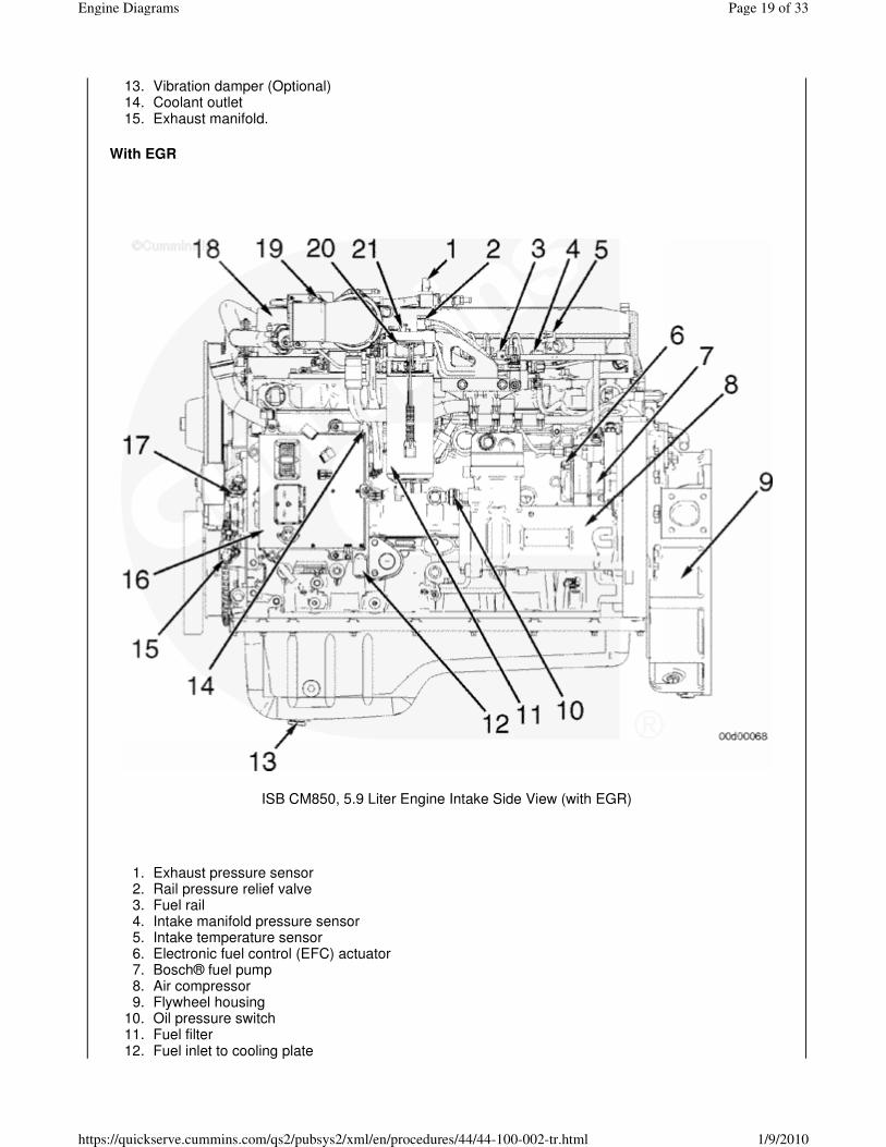
QSB CM850, 5.9 Liter Marine Engine (Top View)
Aftercooler sea water outlet1.Aftercooler housing2.Intake air connection from aftercooler to intake manifold3.Intake manifold pressure and temperature port4.Fuel rail pressure sensor5.Sea water supply to fuel cooler6.Sea water pump inlet7.Sea water pump8.Engine oil fill9.Coolant temperature sensor10.Coolant pressure side vent petcock11.Heat exchanger engine coolant inlet12.Heat exchanger13.Coolant fill neck14.Expansion tank15.Sea water outlet from heat exchanger16.Exhaust temperature and back pressure port17.Exhaust outlet connection18.Closed crankcase breather blow-by connection19.Air inlet restriction indicator20.Air cleaner connection21.Closed crankcase breather/air cleaner assembly22.
Page 28 of 33Engine Diagrams
1/9/2010https://quickserve.cummins.com/qs2/pubsys2/xml/en/procedures/44/44-100-002-tr.html

QSB CM850, 5.9 Liter Marine Engine Sterndrive™ (Starboard View)
Boat transom1.Steering cylinder2.Bearing support assembly3.Exhaust elbow4.Tailstock assembly5.Driveshaft6.Trim cylinder zinc anode7.Ventilation plate zinc anode8.Sterndrive™9.Trim cylinder.10.
Page 29 of 33Engine Diagrams
1/9/2010https://quickserve.cummins.com/qs2/pubsys2/xml/en/procedures/44/44-100-002-tr.html

QSB CM850, 5.9 Liter Marine Engine Sterndrive™ (Top View)
Sterndrive™1.Trim cylinder2.Steering cylinder (not shown)3.Bearing support assembly4.Tailstock assembly5.Driveshaft6.Trim cylinder7.Ventilation plate zinc anode (bottom of ventilation plate)8.Trim cylinder zinc anode.9.
Page 30 of 33Engine Diagrams
1/9/2010https://quickserve.cummins.com/qs2/pubsys2/xml/en/procedures/44/44-100-002-tr.html

Zeus™ 3500 Non Drop-Box (Starboard View)
Sea water outlet from engine1.Sea water outlet bypass to muffler2.Sea water inlet and seacock3.Steering and transmission fluid drain 4.Gear oil drain plug5.Sea water outlet valve6.Transmission drain7.Steering and transmission oil cooler8.Exhaust outlet connection.9.
Zeus™ 3500 Non Drop-Box (Port View)
Gear housing oil reservoir and fill1.Backup steering pump fill and dipstick2.Steering back up pump3.Steering and trim tab fluid filter4.Trim tab and zinc anode 5.Propeller shaft6.Drive skeg7.Gear housing8.Sea water inlet and seacock9.Drive shaft (under shield)10.Drive shaft shield.11.
Page 31 of 33Engine Diagrams
1/9/2010https://quickserve.cummins.com/qs2/pubsys2/xml/en/procedures/44/44-100-002-tr.html

Zeus™ 3500 (Top View)
Transmission dipstick1.Steering and transmission fluid reservoir fill2.Transmission filter.3.
Zeus™ 3500 Drop Box (Starboard View)
Exhaust riser1.
Page 32 of 33Engine Diagrams
1/9/2010https://quickserve.cummins.com/qs2/pubsys2/xml/en/procedures/44/44-100-002-tr.html

Transmission drop box.2.
Zeus™ 3500 Drop Box (Port View)
Drop box drain plug1.
Last Modified: 19-Jun-2008
Feedback / Help
Copyright © 2000-2009 Cummins Inc. All rights reserved.
Page 33 of 33Engine Diagrams
1/9/2010https://quickserve.cummins.com/qs2/pubsys2/xml/en/procedures/44/44-100-002-tr.html