10 Thomas, Irvine, CA 92618, USA Toll Free: (800) 23-FUTEK Telephone
59
10 Thomas, Irvine, CA 92618, USA Toll Free: (800) 23-FUTEK Telephone: (949) 465-0900 Fax: (949) 465-0905 [email protected] www.futek.com
Transcript of 10 Thomas, Irvine, CA 92618, USA Toll Free: (800) 23-FUTEK Telephone

10 Thomas, Irvine, CA 92618, USA
Toll Free: (800) 23-FUTEK Telephone: (949) 465-0900
Fax: (949) 465-0905 [email protected] www.futek.com

SENSIT Test and Measurement Version 2.2.4000.0 Software Manual
10 Thomas, Irvine, CA 92618 USA T (949) 465-0900 F (949) 465-0905 [email protected] www.futek.com
2
Table of Contents Software Overview ................................................................................................................................................ - 4 - Product Key ............................................................................................................................................................ - 5 - Model Selection ...................................................................................................................................................... - 6 - Device Selection ..................................................................................................................................................... - 7 - Menu ........................................................................................................................................................................ - 8 -
File ....................................................................................................................................................................... - 8 - Edit ...................................................................................................................................................................... - 8 - View .................................................................................................................................................................... - 8 - Format ................................................................................................................................................................ - 8 - Help .................................................................................................................................................................... - 9 -
Display Mode ....................................................................................................................................................... - 10 - Display Table ................................................................................................................................................... - 10 -
How to Use the Display Settings ............................................................................................................. - 10 - Display Settings .......................................................................................................................................... - 11 -
Display Front Panel ........................................................................................................................................ - 14 - Keypad Functions ...................................................................................................................................... - 14 - Software Display ........................................................................................................................................ - 15 -
Sum Channel ................................................................................................................................................... - 16 - How to Use the Sum Channel .................................................................................................................. - 16 - Other Sum Channel Features .................................................................................................................... - 17 -
Math Channel .................................................................................................................................................. - 18 - How to Use the Math Channel ................................................................................................................. - 18 - Other Math Channel Features .................................................................................................................. - 19 -
Math Channel Calculator ............................................................................................................................... - 20 - Data Logging Mode ............................................................................................................................................. - 21 -
Data Logging Setup ........................................................................................................................................ - 21 - How to Setup and Start a Data Logging Test ......................................................................................... - 21 - Data Logging Settings................................................................................................................................ - 22 -
Data Logging Graph ....................................................................................................................................... - 24 - How to Zoom In and Out .......................................................................................................................... - 24 - Other Data Logging Graph Features ....................................................................................................... - 24 - Graph Options ............................................................................................................................................ - 26 -
Data Logging Properties ................................................................................................................................ - 28 - Data Logging Registers .................................................................................................................................. - 29 - Data Logging Table......................................................................................................................................... - 30 -
Live Graphing Mode ........................................................................................................................................... - 31 - Live Graph Settings ........................................................................................................................................ - 31 -
How to Setup and Start a Live Graph ..................................................................................................... - 31 - Other Features ............................................................................................................................................ - 32 - Live Graph Settings.................................................................................................................................... - 33 -
Live Graph ....................................................................................................................................................... - 35 - How to Zoom In and Out .......................................................................................................................... - 35 - Other Live Graph Features ....................................................................................................................... - 35 -
Live Graph Properties .................................................................................................................................... - 39 - Live Graph Registers ...................................................................................................................................... - 40 -

SENSIT Test and Measurement Version 2.2.4000.0 Software Manual
10 Thomas, Irvine, CA 92618 USA T (949) 465-0900 F (949) 465-0905 [email protected] www.futek.com
3
Live Graph Table............................................................................................................................................. - 41 - Calibration Mode ................................................................................................................................................. - 42 -
Warning ............................................................................................................................................................ - 42 - Calibration ....................................................................................................................................................... - 43 -
How to Setup and Start a Live Calibration ............................................................................................. - 43 - Other Calibration Features........................................................................................................................ - 43 - Calibration Settings .................................................................................................................................... - 44 - Calibration Direction Table(s) .................................................................................................................. - 46 -
Scale Method ................................................................................................................................................... - 47 - How to Use the Scale Method .................................................................................................................. - 47 -
Shunt ................................................................................................................................................................. - 48 - How to Use the Shunt ................................................................................................................................ - 48 -
Culture Information ............................................................................................................................................ - 49 - Culture Information ........................................................................................................................................ - 49 -
How to Use the Culture Information ...................................................................................................... - 49 - Additional Information ....................................................................................................................................... - 50 -
System Properties............................................................................................................................................ - 50 - Other System Properties Features ............................................................................................................ - 50 -
Sensor Properties ............................................................................................................................................ - 51 - Other Sensor Properties Features ............................................................................................................. - 51 -
Unit Conversions ............................................................................................................................................ - 52 - Unit Codes ....................................................................................................................................................... - 53 -
Transducer Electronic Data Sheets (TEDS) ...................................................................................................... - 54 - TEDS Template ................................................................................................................................................ - 54 -
How to Read TEDS Template Information ............................................................................................. - 54 - Basic TEDS Options ................................................................................................................................... - 54 - How to Create New TEDS Template Information ................................................................................. - 54 - How to Save TEDS Template Information ............................................................................................. - 55 -
TEDS Data ........................................................................................................................................................ - 56 - How to Read TEDS Data ........................................................................................................................... - 56 - How to Write TEDS Data .......................................................................................................................... - 56 -
About ..................................................................................................................................................................... - 57 - About SENSIT Test and Measurement ........................................................................................................ - 57 -
Minimum System Requirements ....................................................................................................................... - 58 - Hardware Requirements ................................................................................................................................ - 58 - Software Requirements .................................................................................................................................. - 58 -
Release Information ............................................................................................................................................. - 59 - Copyright .............................................................................................................................................................. - 59 - Disclaimer ............................................................................................................................................................. - 59 - Contact Information ............................................................................................................................................ - 59 -

SENSIT Test and Measurement Version 2.2.4000.0 Software Manual
10 Thomas, Irvine, CA 92618 USA T (949) 465-0900 F (949) 465-0905 [email protected] www.futek.com
4
Software Overview This software manual outlines all of the features available in the SENSIT Test and Measurement software. This software is for computers running Windows based 32-bit or 64-bit (x86 or x64) operating systems.
SENSIT Test and Measurement Version 2.2.4000.0 Software Manual
10 Thomas, Irvine, CA 92618 USA T (949) 465-0900 F (949) 465-0905 [email protected] www.futek.com
5
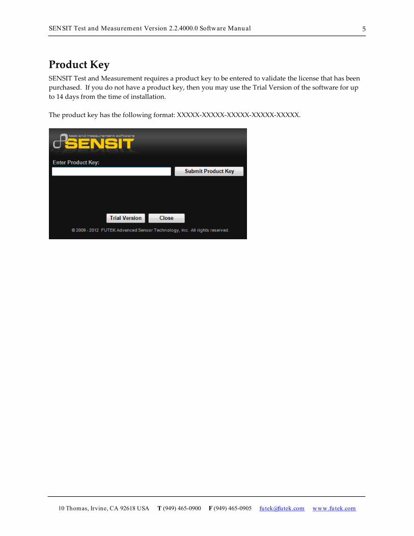
Product Key SENSIT Test and Measurement requires a product key to be entered to validate the license that has been purchased. If you do not have a product key, then you may use the Trial Version of the software for up to 14 days from the time of installation. The product key has the following format: XXXXX-XXXXX-XXXXX-XXXXX-XXXXX.

SENSIT Test and Measurement Version 2.2.4000.0 Software Manual
10 Thomas, Irvine, CA 92618 USA T (949) 465-0900 F (949) 465-0905 [email protected] www.futek.com
6
Model Selection SENSIT Test and Measurement supports the use of several models. When connecting more than one type of model family, the software will require the user to select which model(s) to communicate with when running the application.

SENSIT Test and Measurement Version 2.2.4000.0 Software Manual
10 Thomas, Irvine, CA 92618 USA T (949) 465-0900 F (949) 465-0905 [email protected] www.futek.com
7
Device Selection SENSIT Test and Measurement automatically populates all of the available device serial numbers into a drop-down list. Each device is assigned to a unique row in ascending order by serial number. The device selection table can be used to enable or disable each of the devices and to assign a serial number to a specific device number. There is an option to save the settings for each device that has been enabled or disabled, which will be reflected the next time the software is executed. Please Note: 1. Each serial number must be unique and cannot be assigned to more than one row. 2. Only devices that have been enabled will be used in the software. 3. If a device number has been disabled, then the subsequent devices will be ignored in the software.

SENSIT Test and Measurement Version 2.2.4000.0 Software Manual
10 Thomas, Irvine, CA 92618 USA T (949) 465-0900 F (949) 465-0905 [email protected] www.futek.com
8
Menu
File Load Default Settings – loads the default display, data logging, live graphing, color, and font settings of the software. Load Saved Settings – loads the previously saved changes to the display, data logging, live graphing, color, and font settings. Save Current Settings – saves the current changes to the display, data logging, live graphing, color, and font settings. Exit – will close the application.
Edit Display Table – allows the user to change the heading of the columns on the display table.
View Display Table – Minimize – allows the user to minimize the columns on the display table that are not being used. Display Front Panel – Orientation – allows the user to change the orientation of the display front panel to horizontal or vertical. Display Front Panel – Zoom – allows the user to change the size of the display front panel between 100% and 300% of actual size.
Format Culture Information – allows the user to change the number, date, and time format associated with the software based on regional language settings. Font – allows the user to change the font of the display table. Background Color – allows the user to change the background colors of the display table and display front panel. Foreground Color – allows the user to change the foreground (text) colors of the display table and display front panel.

SENSIT Test and Measurement Version 2.2.4000.0 Software Manual
10 Thomas, Irvine, CA 92618 USA T (949) 465-0900 F (949) 465-0905 [email protected] www.futek.com
9
Help Additional Information – allows the user to view the system properties, sensor properties, unit conversions and unit codes. Transducer Electronic Data Sheets (TEDS) – allows the user to view the TEDS template data. Software Manual – allows the user to view a .pdf of the software manual that relates to the version of their software. About SENSIT Test and Measurement – allows the user to view information about the software and the manufacturer.

SENSIT Test and Measurement Version 2.2.4000.0 Software Manual
10 Thomas, Irvine, CA 92618 USA T (949) 465-0900 F (949) 465-0905 [email protected] www.futek.com
10
Display Mode
Display Table This tab displays all of the relevant information that is related to the reading of each device. The settings of each device can be controlled individually using the right click to display the settings menu.
How to Use the Display Settings 1. Click on the device whose settings will be changed, so that the device is highlighted. 2. Right click anywhere on the Display Table and select the desired Display Settings to change for that
device.

SENSIT Test and Measurement Version 2.2.4000.0 Software Manual
10 Thomas, Irvine, CA 92618 USA T (949) 465-0900 F (949) 465-0905 [email protected] www.futek.com
11
Display Settings
Device Settings The device settings allow the user to view/modify settings that relate to a specific device. In order to view the settings menu, the user needs to right click on the desired device’s row in the display table.
Mode This device setting allows the user to select the display mode. This feature is useful when monitoring clockwise and counter clockwise torque values, tension and compression load values, and pressure values. Each mode can be useful depending on the application or type of test being performed. Examples are listed below the description of each mode. Tracking Mode – allows continuous readings to be displayed on the screen. For example: This mode would be useful in monitoring a live test. Peak Mode – allows a peak (high) reading to be displayed on the screen. The peak reading will only change if a reading greater than the current peak reading is registered. For example: This mode would be useful in measuring the greatest torque or load value in the positive direction. Valley Mode – allows a valley (low) reading to be displayed on the screen. The valley reading will only change if a reading less than the current valley reading is registered. For example: This mode would be useful in measuring the greatest torque or load value in the negative direction.
Reset This device setting allows the user to reset the peak or valley readings. Peak Reset – allows the max peak value shown to be reset back to zero so further peak values can be observed. Valley Reset – allows the max valley value shown to be reset back to zero so further valley values can be observed.
Tare / Gross This device setting allows the user to toggle between the tare and gross readings.

SENSIT Test and Measurement Version 2.2.4000.0 Software Manual
10 Thomas, Irvine, CA 92618 USA T (949) 465-0900 F (949) 465-0905 [email protected] www.futek.com
12
Tare – allows any existing preloads or readings to be zeroed out or nullified on the screen. For example: This function should be used before performing any tests or calibrations in order to receive an accurate reading. Gross – shows the actual value of the display, including the true zero reading.
Decimal Format This device setting allows the user to select how many digits after the decimal point to display. More digits after the decimal point can be used for measuring lower loads with relatively large units.
Convert Units This device setting allows the output units to be converted to a desired unit by selecting from the list available in the pull down menu. A unit can only be converted to another unit of the same type of measurement. For example: lb to kg, N-m to ft-lb, or psi to bar
Sampling Rate This device setting allows the user to select the number of samples taken per second. A higher sampling rate would be desired for dynamic applications, whereas a lower sampling rate would be sufficient for static applications. Selecting different values for the sampling rate will affect the number of bits of resolution.
Average Setting This device setting allows the number of samples taken, before an average is calculated, to be changed. Selecting a higher number of samples will result in a steadier reading. Disable Average – stops averaging samples and updates the display as the input is read. Moving Average – is used to smooth out fluctuations in the sensor’s output. For each new sample, the oldest sample is discarded and a new average is calculated. Mean Average – is used in static applications where the output changes slowly over time. The mean average waits until the number of samples to average has been received before calculating the average.
Change Polarity This device setting allows the user to reverse the sign that is displayed.
Keypad Locked This device setting allows the user to lock/unlock the physical keypad on the IHH/IPM.
Linearization This device setting takes into account the nonlinearity of the sensor and compensates for it. This function is useful for sensors whose nonlinearity does not meet specifications.
Shunt Verification This device setting is used to verify the calibration of a sensor. When shunted, the value should be close to the initial shunt value on the calibration certificate. If the value is significantly off, then the sensor would need to be recalibrated.

SENSIT Test and Measurement Version 2.2.4000.0 Software Manual
10 Thomas, Irvine, CA 92618 USA T (949) 465-0900 F (949) 465-0905 [email protected] www.futek.com
13
Global Settings The global settings allow the user to view/modify settings that relate to all devices. In order to view the settings menu, the user needs to right click on the desired device’s row in the display table.
Display Refresh Rate This setting allows the user to select how fast the readings will update on the display table and display front panel.

SENSIT Test and Measurement Version 2.2.4000.0 Software Manual
10 Thomas, Irvine, CA 92618 USA T (949) 465-0900 F (949) 465-0905 [email protected] www.futek.com
14
Display Front Panel This tab displays the front panel user interface. The software provides access to all of the same functions of the keypad on the IHH/IPM hardware and displays the same messages as the LCD. All functions performed by the software are the same as if they were performed using the hardware with the exception of the Power Key. The Power Key can only be used by the hardware.
Keypad Functions
Battery / Enter Key (IHH only) This key is used to display the battery life when used in normal mode. This Key is used as an enter key when used in menu mode.
Channel / Enter Key (IPM only) This key is used to display the channel information when used in normal mode. This Key is used as an enter key when used in menu mode.

SENSIT Test and Measurement Version 2.2.4000.0 Software Manual
10 Thomas, Irvine, CA 92618 USA T (949) 465-0900 F (949) 465-0905 [email protected] www.futek.com
15
Tare / Gross Key This key is used to tare (zero) the current readings or display the gross value of the current readings when used in normal mode. This Key is used as an up arrow when used in menu mode.
Display / Back Key This key is used to switch between various states on the LCD display when used in normal mode. This Key is used as a back key when used in menu mode.
Reset Key This key is used to reset the current readings when used in normal mode. This Key is used as a left arrow when used in menu mode.
Menu Key This key is used to enter the menu mode.
Unit Key This key is used to switch between various engineering units when used in normal mode. This Key is used as a right arrow when used in menu mode.
Shunt / Exit Key This key is used to enable the shunt value when used in normal mode. This Key is used to exit when used in menu mode.
Track / Hold Key This key is used to track the current readings or hold the current displayed values when used in normal mode. This Key is used as a down arrow when used in menu mode.
Power Key This key has no function in the software. It can only be used directly on the IHH/IPM hardware keypad.
Software Display
Software Display This is used to replicate the characters displayed on the IHH/IPM LCD.

SENSIT Test and Measurement Version 2.2.4000.0 Software Manual
10 Thomas, Irvine, CA 92618 USA T (949) 465-0900 F (949) 465-0905 [email protected] www.futek.com
16
Sum Channel This feature allows the user to sum the readings from multiple devices into one reading that is shown on the Display Table. For example: It can be used to find the total weight that a scale using multiple sensors is supporting.
How to Use the Sum Channel 1. Click Enable Channel. 2. Select the values that will be summed (Tracking Value, Peak Value, or Valley Value). 3. Select the devices that will be added together. 4. Click on the Display Table tab. The Sum row will be displayed with the appropriate reading.

SENSIT Test and Measurement Version 2.2.4000.0 Software Manual
10 Thomas, Irvine, CA 92618 USA T (949) 465-0900 F (949) 465-0905 [email protected] www.futek.com
17
Other Sum Channel Features Clear Sum Settings – clears the sum value and resets all of the summing functions to default settings. Sum Decimal Format – changes the number of digits displayed after the decimal point in the reading. Sum All Devices – enables the addition of all the devices available.

SENSIT Test and Measurement Version 2.2.4000.0 Software Manual
10 Thomas, Irvine, CA 92618 USA T (949) 465-0900 F (949) 465-0905 [email protected] www.futek.com
18
Math Channel This feature allows the user to perform simple mathematical calculations on the live reading. With the proper scale factor, this feature can be used to convert units of a live reading to a custom unit that is not available on the Display Table.
How to Use the Math Channel 1. Click Enable Channel. 2. Select the values used in the calculation (Tracking Value, Peak Value, or Valley Value). 3. Click Show Calculator, and perform the appropriate calculation to the desired channel. 4. Close the Math Channel Calculator and click the Display Table tab. The Math row will be
displayed with the appropriate calculations.

SENSIT Test and Measurement Version 2.2.4000.0 Software Manual
10 Thomas, Irvine, CA 92618 USA T (949) 465-0900 F (949) 465-0905 [email protected] www.futek.com
19
Other Math Channel Features Clear Math Settings – clears the calculation and resets the math channel functions to default settings. Math Decimal Format – changes the number of digits displayed after the decimal point in the reading. Math Channel Units – The units entered here will be shown on the Display Table tab for the Math row.

SENSIT Test and Measurement Version 2.2.4000.0 Software Manual
10 Thomas, Irvine, CA 92618 USA T (949) 465-0900 F (949) 465-0905 [email protected] www.futek.com
20
Math Channel Calculator This feature allows the user to perform simple mathematical calculations. It performs all of the functions found on a standard calculator such as: multiplication (*), division (/), addition (+), and subtraction (-). There are several memory functions including: memory clear (MC), memory recall (MR), memory store (MS) and memory plus (M+). The calculator also includes functions for finding the square root (sqrt) and inverse (1/x) of a number. One feature that is unique to the math channel calculator is the CH key which should be used when applying a calculation to one of the channels. The user should press the CH key followed by the number of the channel.

SENSIT Test and Measurement Version 2.2.4000.0 Software Manual
10 Thomas, Irvine, CA 92618 USA T (949) 465-0900 F (949) 465-0905 [email protected] www.futek.com
21
Data Logging Mode
Data Logging Setup This tab allows the user to set all of the necessary parameters to begin logging data. Please Note: Some Data Logging features may require Microsoft Excel.
How to Setup and Start a Data Logging Test 1. Click Settings to modify the Data Logging Settings. 2. Click File Path and specify a filename and path for the data file. 3. Click Start Test to begin the test. The test will be complete after the predetermined test
duration and the data will be exported to a file. The data file will open and the USB Software will automatically graph the recorded data onto the Data Logging Graph tab.

SENSIT Test and Measurement Version 2.2.4000.0 Software Manual
10 Thomas, Irvine, CA 92618 USA T (949) 465-0900 F (949) 465-0905 [email protected] www.futek.com
22
Data Logging Settings
Models The user must select the model to be used for data logging.
Devices The user must select the device(s) to be used for data logging.
Start Data Logging There are three options to specify when to start data logging: (1) Immediately, (2) Above Threshold, or (3) Below Threshold.
Test Duration Once the data logging begins, the test duration specifies the total length of time in hours, minutes and seconds that the data will be collected.

SENSIT Test and Measurement Version 2.2.4000.0 Software Manual
10 Thomas, Irvine, CA 92618 USA T (949) 465-0900 F (949) 465-0905 [email protected] www.futek.com
23
Threshold Value The threshold value allows the user to select a device and a specific threshold that the reading must be above or below in order for the data logging to begin. This value will be ignored if start data logging is set to begin immediately.
X-Axis Values The x-axis of the Data Logging Graph can be configured by Sample Number or Time. The Time will be formatted based on the Culture Information.
Microsoft Excel Options When exporting data to an Excel file, the user will have the option to enable or disable the automatic charting feature. If it is enabled, then a chart that resembles the one in the software will also be created in the Excel file. If it is disabled, then there will not be any charts in the Excel file. When collecting a large amount of data, it may be preferable to disable the auto chart in order shorten the amount of time that it takes to export the data to Excel.
Apply Settings The settings must be applied prior to starting a new data logging test.

SENSIT Test and Measurement Version 2.2.4000.0 Software Manual
10 Thomas, Irvine, CA 92618 USA T (949) 465-0900 F (949) 465-0905 [email protected] www.futek.com
24
Data Logging Graph This tab is used to view a graph of the data collected from the data logging test. The tracking, peak, and valley values are shown for each device that is enabled.
How to Zoom In and Out
Zoom In Click and drag a rectangular box on the graph. The highlighted area will be zoomed into.
Zoom Out 1. Click the button on the y-axis to zoom out from the y-axis. 2. Click the button on the x-axis to zoom out from the x- axis.
Other Data Logging Graph Features

SENSIT Test and Measurement Version 2.2.4000.0 Software Manual
10 Thomas, Irvine, CA 92618 USA T (949) 465-0900 F (949) 465-0905 [email protected] www.futek.com
25
How to View a Graph from another Device Right click on the graph, and select Graph Device. Select the desired device to graph from the pull down menu.
How to Change the Graph Range The graph range of the x-axis can be changed by selecting the graph range and specifying a maximum value to graph to.
How to Change the Graph Options Right click on the graph, and select Graph Options.

SENSIT Test and Measurement Version 2.2.4000.0 Software Manual
10 Thomas, Irvine, CA 92618 USA T (949) 465-0900 F (949) 465-0905 [email protected] www.futek.com
26
Graph Options The graph options are used to change the various settings that control how the graph is displayed.
Color This tab allows the user to change the color of the background, foreground (text), grid, and cursor.
Font This tab allows the user to change the font settings (font, style, size) for the titles, labels, and legend.
Label This tab allows the user to change the titles of the graph, x-axis, and y-axis.
Legend This tab allows the user to change the alignment and docking location of the legend.
Series This tab allows the user to change the line border width of the graph that is plotted.

SENSIT Test and Measurement Version 2.2.4000.0 Software Manual
10 Thomas, Irvine, CA 92618 USA T (949) 465-0900 F (949) 465-0905 [email protected] www.futek.com
27
X-Axis This tab allows the user to change the settings of the x-axes (grid interval, tick mark intervals, and min. and max. value).
Y-Axis This tab allows the user to change the settings of the y-axes (grid interval, tick mark intervals, and min. and max. value).
X-Cursor This tab allows the user to change the settings of the x-axis cursor (cursor interval, line width, and selection start and end).
Y-Cursor This tab allows the user to change the settings of the y-axis cursor (cursor interval, line width, and selection start and end).

SENSIT Test and Measurement Version 2.2.4000.0 Software Manual
10 Thomas, Irvine, CA 92618 USA T (949) 465-0900 F (949) 465-0905 [email protected] www.futek.com
28
Data Logging Properties This tab shows the status of each device that is plugged in, whether it is enabled or disabled. It can be used as a reminder to the user as to which devices are enabled or disabled during the data logging test.
SENSIT Test and Measurement Version 2.2.4000.0 Software Manual
10 Thomas, Irvine, CA 92618 USA T (949) 465-0900 F (949) 465-0905 [email protected] www.futek.com
29
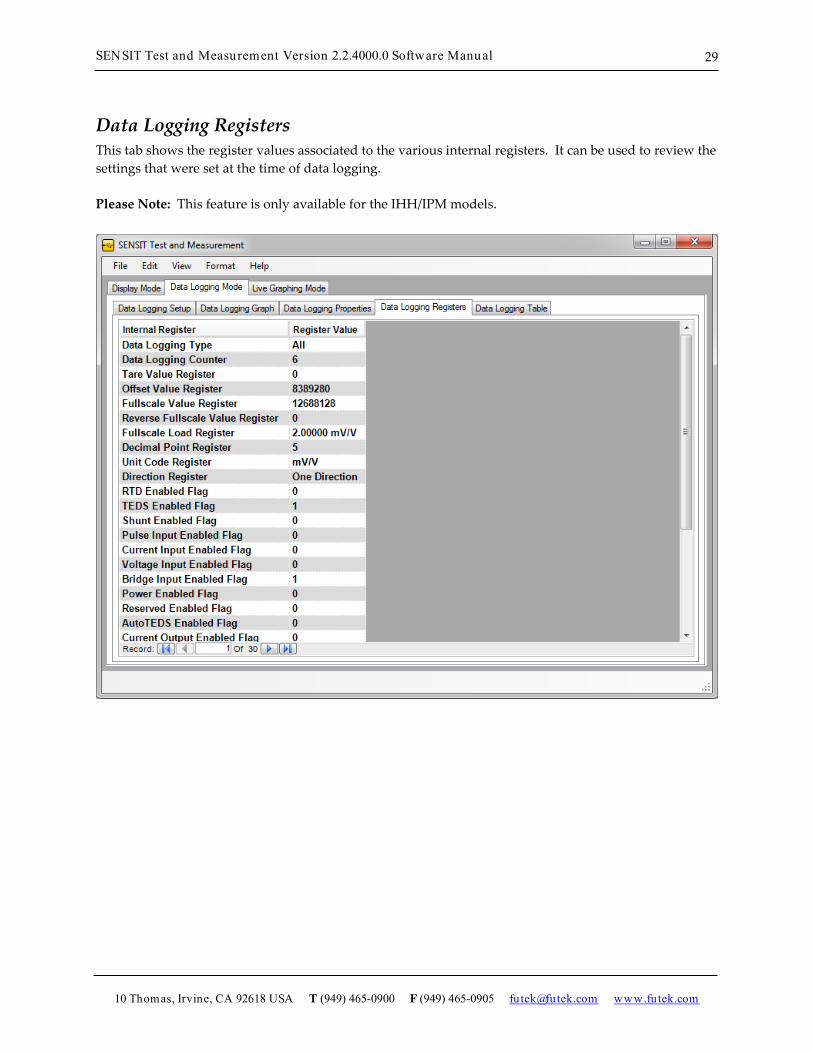
Data Logging Registers This tab shows the register values associated to the various internal registers. It can be used to review the settings that were set at the time of data logging. Please Note: This feature is only available for the IHH/IPM models.

SENSIT Test and Measurement Version 2.2.4000.0 Software Manual
10 Thomas, Irvine, CA 92618 USA T (949) 465-0900 F (949) 465-0905 [email protected] www.futek.com
30
Data Logging Table This tab shows a table of the samples recorded during the data logging session. It can be used as a reference instead of opening the Excel sheet that has been exported after the data logging session has been completed.

SENSIT Test and Measurement Version 2.2.4000.0 Software Manual
10 Thomas, Irvine, CA 92618 USA T (949) 465-0900 F (949) 465-0905 [email protected] www.futek.com
31
Live Graphing Mode
Live Graph Settings This tab allows the user to set all of the necessary parameters to begin live graphing. It will also allow the user to log the data that has been graphed. Please Note: Some Live Graph features may require Microsoft Excel.
How to Setup and Start a Live Graph 1. Click Settings to modify the Live Graph Settings. 2. Click File Path and specify a filename and path for the data file. 3. Click Start Test to begin the test. The tab will automatically switch from Live Graph Settings to Live
Graph once the test has begun. It will complete after the predetermined test duration and export the data to a file.
Please Note: The data logged in Live Graphing Mode is slower than the data logged in Data Logging Mode due to the software updating the graph. If higher data logging speeds are required for certain tests, use the Data Logging Mode instead.

SENSIT Test and Measurement Version 2.2.4000.0 Software Manual
10 Thomas, Irvine, CA 92618 USA T (949) 465-0900 F (949) 465-0905 [email protected] www.futek.com
32
Other Features
Stop Test This will stop the test immediately, and show the recorded samples on the Live Graph Table. The software will then ask if you still want to export the data to a file.

SENSIT Test and Measurement Version 2.2.4000.0 Software Manual
10 Thomas, Irvine, CA 92618 USA T (949) 465-0900 F (949) 465-0905 [email protected] www.futek.com
33
Live Graph Settings
Models The user must select the model to be used for live graphing.
Devices The user must select the device(s) to be used for live graphing.
Start Live Graph There are three options to specify when to start live graphing: (1) Immediately, (2) Above Threshold, or (3) Below Threshold.
Test Duration Once the data logging begins, the test duration specifies the total length of time in hours, minutes and seconds that the data will be collected.

SENSIT Test and Measurement Version 2.2.4000.0 Software Manual
10 Thomas, Irvine, CA 92618 USA T (949) 465-0900 F (949) 465-0905 [email protected] www.futek.com
34
Threshold Value The threshold value allows the user to select a device and a specific threshold that the reading must be above or below in order for the live graph to begin. This value will be ignored if start live graph is set to begin immediately.
X-Axis Values The x-axis of the Live Graph can be configured by Sample Number or Time. The Time will be formatted based on the Culture Information.
Microsoft Excel Options When exporting data to an Excel file, the user will have the option to enable or disable the automatic charting feature. If it is enabled, then a chart that resembles the one in the software will also be created in the Excel file. If it is disabled, then there will not be any charts in the Excel file. When collecting a large amount of data, it may be preferable to disable the auto chart in order shorten the amount of time that it takes to export the data to Excel.
Test Interval The test interval specifies the interval that a request will be made for the latest reading.
Refresh Rate The refresh rate specifies how often the live graph will be updated or refreshed.
Samples to Display The number of samples to display scales the x-axis while the live graph is in progress.
Rotation Values When using a device that has the ability to read an encoder, the user will have the option to enable or disable the rotation values from being displayed in the live graph.
Apply Settings The settings must be applied prior to starting a new live graph test.

SENSIT Test and Measurement Version 2.2.4000.0 Software Manual
10 Thomas, Irvine, CA 92618 USA T (949) 465-0900 F (949) 465-0905 [email protected] www.futek.com
35
Live Graph This tab is used to view the live graph as the test is being performed. The tracking, peak, and valley values are shown for each device that is enabled.
How to Zoom In and Out
Zoom In Click and drag a rectangular box on the graph. The highlighted area will be zoomed into.
Zoom Out 1. Click the button on the y-axis to zoom out from the y-axis. 2. Click the button on the x-axis to zoom out from the x- axis.
Other Live Graph Features

SENSIT Test and Measurement Version 2.2.4000.0 Software Manual
10 Thomas, Irvine, CA 92618 USA T (949) 465-0900 F (949) 465-0905 [email protected] www.futek.com
36
How to Change the Graph Options Right click on the graph, and select Graph Options.
How to Hide the Chart Area If the rotation values are enabled, then the chart will have two chart areas. Chart Area 1 contains the Peak, Tracking, Valley and Power measurements. Chart Area 2 contains the Angle and RPM measurements.
Hide Chart Area You can choose to hide Chart Area 1 or Chart Area 2. The remaining chart will be resized to fill the contents of the Live Graph tab.
Chart Area 1: Visible, Chart Area 2: Visible
The following two images show Chart Area 1 by itself and Chart Area 2 by itself.

SENSIT Test and Measurement Version 2.2.4000.0 Software Manual
10 Thomas, Irvine, CA 92618 USA T (949) 465-0900 F (949) 465-0905 [email protected] www.futek.com
37
Chart Area 1: Visible, Chart Area 2: Hidden

SENSIT Test and Measurement Version 2.2.4000.0 Software Manual
10 Thomas, Irvine, CA 92618 USA T (949) 465-0900 F (949) 465-0905 [email protected] www.futek.com
38
Chart Area 1: Hidden, Chart Area 2: Visible

SENSIT Test and Measurement Version 2.2.4000.0 Software Manual
10 Thomas, Irvine, CA 92618 USA T (949) 465-0900 F (949) 465-0905 [email protected] www.futek.com
39
Live Graph Properties This tab shows the status of each device that is plugged in, whether it is enabled or disabled. It can be used as a reminder to the user as to which devices are enabled or disabled during the live graph test.

SENSIT Test and Measurement Version 2.2.4000.0 Software Manual
10 Thomas, Irvine, CA 92618 USA T (949) 465-0900 F (949) 465-0905 [email protected] www.futek.com
40
Live Graph Registers This tab shows the register values associated to the various internal registers. It can be used to review the settings that were set at the time of data logging. Please Note: This feature is only available for the IHH/IPM models.

SENSIT Test and Measurement Version 2.2.4000.0 Software Manual
10 Thomas, Irvine, CA 92618 USA T (949) 465-0900 F (949) 465-0905 [email protected] www.futek.com
41
Live Graph Table This tab shows a table of the data points recorded during the live graphing session. It can be used as a reference instead of opening the Excel sheet that has been exported after the live graphing session has been completed.

SENSIT Test and Measurement Version 2.2.4000.0 Software Manual
10 Thomas, Irvine, CA 92618 USA T (949) 465-0900 F (949) 465-0905 [email protected] www.futek.com
42
Calibration Mode
Warning
The use of the calibration mode can affect the factory calibration of the device. This feature provides a wide range of capabilities most of which can directly write to the memory (EEPROM) of the device. Once the memory is overwritten, it will be lost forever. Please read this section carefully. If you are unsure how to use the calibration mode or if you are unsure of its effects on memory, please feel free to contact us.

SENSIT Test and Measurement Version 2.2.4000.0 Software Manual
10 Thomas, Irvine, CA 92618 USA T (949) 465-0900 F (949) 465-0905 [email protected] www.futek.com
43
Calibration This tab allows the user to set all of the necessary parameters to perform a live Calibration.
How to Setup and Start a Live Calibration 1. Click Settings to modify the Calibration Settings. 2. Click Generate Test to create the Calibration Direction Table(s). 3. Click Save Parameters to save the settings to the memory (EEPROM) of the device. 4. Click Save Calibration to save the loading points to the memory (EEPROM) of the device. 5. Click Record Shunt to save a calibration shunt value to the memory (EEPROM) of the device.
Other Calibration Features
Recall Calibration This feature allows the user to retrieve the existing calibration settings and values.
Cancel Calibration This feature can be used to stop the calibration that is in progress, please refer to the Warning because some values may have already been written to memory.

SENSIT Test and Measurement Version 2.2.4000.0 Software Manual
10 Thomas, Irvine, CA 92618 USA T (949) 465-0900 F (949) 465-0905 [email protected] www.futek.com
44
Calibration Settings
Technician Name The technician name is for use by FUTEK personnel only. This field will automatically be set to User Defined.
Parameters The user must enter the device’s serial number and select the desired output units, number of loading points and number of digits to display after the decimal point.
Backup Page The backup page is the destination where a complete backup of the calibration will be stored in memory. This field will automatically be set to EEPROM Page 3 (System).
Multiple Directions If the device is going to be calibrated in two directions, then the multiple directions checkbox should be checked.

SENSIT Test and Measurement Version 2.2.4000.0 Software Manual
10 Thomas, Irvine, CA 92618 USA T (949) 465-0900 F (949) 465-0905 [email protected] www.futek.com
45
Please Note: When performing multiple direction calibrations, the user should always complete calibration direction 1 and then calibration direction 2.
Positive Direction (+) The user must enter the capacity and select the direction associated with the device. Direction 1 should always be used as the positive direction.
Negative Direction (-) The user must enter the capacity and select the direction associated with the device. Direction 2 should always be used as the negative direction.
Pulses Per Rotation When using a device that has the ability to read an encoder, the user must enter the number of pulses per rotation.

SENSIT Test and Measurement Version 2.2.4000.0 Software Manual
10 Thomas, Irvine, CA 92618 USA T (949) 465-0900 F (949) 465-0905 [email protected] www.futek.com
46
Calibration Direction Table(s)
Calibration Direction 1 Calibration Direction 1 should always be used as the positive direction. After generating the test, the user must capture the readings for each of the loading points.
Natural Zero Natural Zero (NZ) refers to the output of the sensor when there is no fixture attached or applied. The difference between the values recorded for the Natural Zero and the zero loading point will be subtracted from each subsequent loading point when saving the calibration data. This will allow the software to display zero when there is no fixture attached or applied. When a fixture is attached or applied, the software has a tare/gross option to zero the reading.
Loading Points To capture the ADC Value from the device, simply apply the appropriate load and when ready press the Enter key on your keyboard. Once you have captured all of the loading points, the Save Parameters button will become available. Please refer to How to Setup and Start a Live Calibration to continue.

SENSIT Test and Measurement Version 2.2.4000.0 Software Manual
10 Thomas, Irvine, CA 92618 USA T (949) 465-0900 F (949) 465-0905 [email protected] www.futek.com
47
Scale Method This tab allows the user to set all of the necessary parameters related to the Scaled Method of Calibration.
How to Use the Scale Method 1. Click Enable Scale Method. 2. Click Settings to enter the Scale Method Parameters. 3. Set the Full Scale (mV/V)*, Full Scale (Capacity), and Output Units.
a. Serial Number – The serial number to apply the scaling to. b. Full Scale 1 (mV/V)* – The positive full scale value expressed in mV/V. c. Full Scale 2 (mV/V)* – The negative full scale value expressed in mV/V. d. Full Scale 1 (Capacity) – The positive full scale value in engineering units. e. Full Scale 2 (Capacity) – The negative full scale value in engineering units. f. Output Units – The engineering units that will be applied when scaling.
4. Click Set Parameters to lock the settings. 5. Click Save Parameters to save the scale method settings for future use. * The units should be expressed in the same base units that the original calibration was performed in. If the calibration was performed using mV/V, then the Full Scale 1 and Full Scale 2 should be expressed in mV/V.

SENSIT Test and Measurement Version 2.2.4000.0 Software Manual
10 Thomas, Irvine, CA 92618 USA T (949) 465-0900 F (949) 465-0905 [email protected] www.futek.com
48
Shunt This tab allows the user to compare the calibrated shunt value with the current shunt value. It can be used as a means of verification.
How to Use the Shunt 1. Click Enable Shunt. If the shunt value was recorded during calibration, then the current value
will be compared to it and the percentage difference will be calculated. Please Note: All loads applied to the sensor including any fixtures should be removed.

SENSIT Test and Measurement Version 2.2.4000.0 Software Manual
10 Thomas, Irvine, CA 92618 USA T (949) 465-0900 F (949) 465-0905 [email protected] www.futek.com
49
Culture Information
Culture Information The culture information displays the Number, Date, and Time Format based on the selected regional language. Once the settings have been applied, the formatting will be used throughout the software.
How to Use the Culture Information 1. Select the Regional Language from the drop-down list. 2. Click Apply Settings.

SENSIT Test and Measurement Version 2.2.4000.0 Software Manual
10 Thomas, Irvine, CA 92618 USA T (949) 465-0900 F (949) 465-0905 [email protected] www.futek.com
50
Additional Information
System Properties This tab allows the user to view the current System Properties for each device. The table displays information related to the Firmware settings.
Other System Properties Features
How to Change the System Properties Device Right click on the system properties table, and select a device and profile from the drop down list. The system properties table and the sensor properties table will be updated with the information for the device and profile that are selected. Please Note: System Properties and Select Profile are only available for the IHH/IPM models.

SENSIT Test and Measurement Version 2.2.4000.0 Software Manual
10 Thomas, Irvine, CA 92618 USA T (949) 465-0900 F (949) 465-0905 [email protected] www.futek.com
51
Sensor Properties This tab allows the user to view the current Sensor Properties for each device. The table displays information related to the Software and Firmware settings.
Other Sensor Properties Features
How to Change the Sensor Properties Device Right click on the sensor properties table, and select a device and profile from the drop down list. The system properties table and the sensor properties table will be updated with the information for the device and profile that are selected. Please Note: System Properties and Select Profile are only available for the IHH/IPM models.
SENSIT Test and Measurement Version 2.2.4000.0 Software Manual
10 Thomas, Irvine, CA 92618 USA T (949) 465-0900 F (949) 465-0905 [email protected] www.futek.com
52
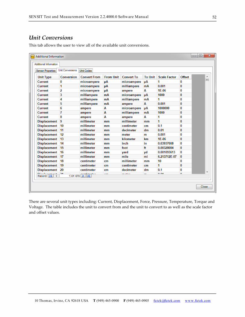
Unit Conversions This tab allows the user to view all of the available unit conversions.
There are several unit types including: Current, Displacement, Force, Pressure, Temperature, Torque and Voltage. The table includes the unit to convert from and the unit to convert to as well as the scale factor and offset values.

SENSIT Test and Measurement Version 2.2.4000.0 Software Manual
10 Thomas, Irvine, CA 92618 USA T (949) 465-0900 F (949) 465-0905 [email protected] www.futek.com
53
Unit Codes This tab allows the user to view all of the available unit codes.
There are several unit types including: Current, Displacement, Force, Pressure, Temperature, Torque and Voltage. The table includes the unit code, name, and abbreviation.

SENSIT Test and Measurement Version 2.2.4000.0 Software Manual
10 Thomas, Irvine, CA 92618 USA T (949) 465-0900 F (949) 465-0905 [email protected] www.futek.com
54
Transducer Electronic Data Sheets (TEDS)
TEDS Template This tab allows the user to read and write to a TEDS Chip. The table displays information related to the Basic TEDS Information and the TEDS Template Information.
How to Read TEDS Template Information Click Read TEDS Template.
Basic TEDS Options Specify if you would like to use the FUTEK Basic TEDS or Standard Basic TEDS.
How to Create New TEDS Template Information Click New TEDS Template and specify the Template ID number in the input box below.

SENSIT Test and Measurement Version 2.2.4000.0 Software Manual
10 Thomas, Irvine, CA 92618 USA T (949) 465-0900 F (949) 465-0905 [email protected] www.futek.com
55
A new template with default values will be created.
How to Save TEDS Template Information After you have filled in all of the required Basic TEDS Information and TEDS Template Information, click Save TEDS Template. Please Note: When writing to the TEDS Chip, the data will be overwritten. Please be cautious as there is no way to retrieve the information once it has been overwritten.

SENSIT Test and Measurement Version 2.2.4000.0 Software Manual
10 Thomas, Irvine, CA 92618 USA T (949) 465-0900 F (949) 465-0905 [email protected] www.futek.com
56
TEDS Data This tab allows the user to read and write to a TEDS Chip. The information is displayed in hexadecimal format and is separated into 32 byte pages.
How to Read TEDS Data Click Read TEDS Data.
How to Write TEDS Data Click Write TEDS Data. Please Note: When writing to the TEDS Chip, the data will be overwritten. Please be cautious as there is no way to retrieve the information once it has been overwritten.

SENSIT Test and Measurement Version 2.2.4000.0 Software Manual
10 Thomas, Irvine, CA 92618 USA T (949) 465-0900 F (949) 465-0905 [email protected] www.futek.com
57
About
About SENSIT Test and Measurement This form allows the user to view all of the information about the software and the manufacturer.

SENSIT Test and Measurement Version 2.2.4000.0 Software Manual
10 Thomas, Irvine, CA 92618 USA T (949) 465-0900 F (949) 465-0905 [email protected] www.futek.com
58
Minimum System Requirements
Hardware Requirements Hardware Requirements
1 Device 1 Device 4 Devices 8 Devices 16 Devices
Hardware Minimum Recommended
Computer Processor x86 800 MHz 2.0 GHz 2.0 GHz 2.0 GHz 2.0 GHz x64 800 MHz 2.5 GHz 2.5 GHz 2.5 GHz 2.5 GHz
System Memory x86 512 MB 2.0 GB 4.0 GB 4.0 GB 4.0 GB x64 1.0 GB 4.0 GB 6.0 GB 8.0 GB 12.0 GB
Hard Disk Drive 20.0 GB 40.0 GB 40.0 GB 40.0 GB 40.0 GB Available Disk Space 10.0 GB 10.0 GB 10.0 GB 10.0 GB 10.0 GB
Disk Drive CD CD-ROM CD-ROM CD-ROM CD-ROM CD-ROM DVD DVD-ROM DVD-ROM DVD-ROM DVD-ROM DVD-ROM
Screen Resolution Standard SVGA HD 1080 HD 1080 HD 1080 HD 1080 W x H 800 x 600 1920 x 1080 1920 x 1080 1920 x 1080 1920 x 1080
USB Port USB 2.0 USB 2.0 USB 2.0 USB 2.0 USB 2.0
Software Requirements Software Requirements
Software Minimum Recommended
Operating System
Microsoft Windows XP Microsoft Windows XP Microsoft Windows Vista Microsoft Windows Vista Microsoft Windows 7 Microsoft Windows 7
Microsoft Office Excel 2003 2003 or later Microsoft .Net Framework 4 4.0 or later FTDI Driver CDM 2.08.02 CDM 2.08.02 or later

SENSIT Test and Measurement Version 2.2.4000.0 Software Manual
10 Thomas, Irvine, CA 92618 USA T (949) 465-0900 F (949) 465-0905 [email protected] www.futek.com
59
Release Information FUTEK USB Software Version 2.0.0.0 User’s Manual – Initial Release January 2011 SensIT USB Software Version 2.0.4000.0 Software Manual – Release July 2011 SensIT Test and Measurement Version 2.1.4000.0 Software Manual – Release November 2011 SENSIT Test and Measurement Version 2.2.4000.0 Software Manual – Release April 2012
Copyright Copyright © FUTEK Advanced Sensor Technology, Inc. 2009-2012.
Disclaimer Neither the whole nor any part of the information contained in, or the product described in this manual, may be adapted or reproduced in any material or electronic form without the prior written consent of the copyright holder. This product and its documentation are supplied on an as-is basis and no warranty as to their suitability for any particular purpose is either made or implied. This document provides preliminary information that may be subject to change without notice.
Contact Information FUTEK Advanced Sensor Technology, Inc. 10 Thomas, Irvine, CA 92618, USA Toll Free: (800) 23-FUTEK Telephone: (949) 465-0900 Fax: (949) 465-0905 Email (All Inquires): [email protected] Website URL: www.futek.com