10 Mb/s Single Twisted Pair Ethernet DC Powering · 10 Mb/s Single Twisted Pair Ethernet DC...
19
10 Mb/s Single Twisted Pair Ethernet DC Powering Steffen Graber Pepperl+Fuchs 1 1/8/2017 IEEE P802.3cg 10 Mb/s Single Twisted Pair Ethernet Task Force
Transcript of 10 Mb/s Single Twisted Pair Ethernet DC Powering · 10 Mb/s Single Twisted Pair Ethernet DC...

10 Mb/s Single Twisted Pair Ethernet
DC Powering
Steffen Graber
Pepperl+Fuchs
11/8/2017IEEE P802.3cg 10 Mb/s Single Twisted Pair Ethernet Task Force

1/8/2017IEEE P802.3cg 10 Mb/s Single Twisted Pair Ethernet Task Force 2
Overview
• Cable Resistance
• Wire Stranding
• Current Fieldbus Installations
• Fieldbus Calculation Example
• 10SPE Calculation Example
• 10SPE Powering Remarks
• 10SPE Power Profile Ideas

Cable Resistance
• Fieldbus type A cable is specified in IEC 61158-2.
• The following table gives information about the DC resistance of commonly used
fieldbus type A cables at 20 deg C (68 deg F) for different wire diameters:
• The values in the table show the loop resistance, the resistance of a single wire is only
half of the values given in the table above.
• Especially when transmitting higher power to the field, the thicker wire diameters will be
required to reduce the power losses over long run trunk cables.
IEEE P802.3cg 10 Mb/s Single Twisted Pair Ethernet Task Force 31/8/2017
Wire diameter Loop resistance for 1000 m at 20 deg C
AWG18 (0.82 mm²) max. 43.6 ohms
AWG16 (1.3 mm²) max. 28.5 ohms
AWG14 (2.1 mm²) max. 17.9 ohms

Cable Resistance
• Commercial grade copper is having a typical temperature coefficient of about
α = 4.1 * 10-3 K-1.
• Assuming a maximum ambient temperature of 70 deg C (158 deg F), this will lead to a
20.5 % higher loop resistance, like stated in the table below:
• Depending on the installation conditions, typically only a part of the cable will run at a
maximum ambient temperature of 70 deg C, while other parts of the cable will run at
lower temperatures.
• Therefore the resistance values given above are worst case values.
IEEE P802.3cg 10 Mb/s Single Twisted Pair Ethernet Task Force 41/8/2017
Wire diameter Loop resistance for 1000 m at 70 deg C
AWG18 (0.82 mm²) max. 52.6 ohms
AWG16 (1.3 mm²) max. 34.4 ohms
AWG14 (2.1 mm²) max. 21.6 ohms

Wire Stranding
• For the AWG18 cables there exist versions based on solid wires and stranded wires.
• For the AWG14 and AWG16 cables practically only versions with 7 stranded wires per conductor are
currently available.
• Reason for this is to reduce the risk of mechanical stress within the higher diameter cables during
installation and when using a small bending radius.
• Even, if there is no difference from DC resistance point of view using solid conductors or stranded
wires, due to the proximity effect the insertion loss of a cable with stranded wires is higher than that
of a cable using solid conductors.
• As AWG14/7 and AWG16/7 cables still have a lower insertion loss than AWG18/1 cables, it could
make sense to use a worst-case AWG18/1 model for the insertion loss.
• For AWG18/7, AWG18/32 and other cables (e.g. also existing smaller wire diameter cables) the
maximum allowed cable length may be reduced, until the insertion loss fits to the cable model.
IEEE P802.3cg 10 Mb/s Single Twisted Pair Ethernet Task Force 51/8/2017
Wire diameter Wire Stranding
AWG18 (0.82 mm²) AWG18/1 (one solid conductor)
AWG18/7 (7 stranded wires per conductor)
AWG18/32 (32 stranded wires per conductor, highly flexible cable)
AWG16 (1.3 mm²) AWG16/7 (7 stranded wires per conductor)
AWG14 (2.1 mm²) AWG14/7 (7 stranded wires per conductor)

Current Fieldbus Installations
• Actual fieldbus installations are typically powered using power supplies with a maximum
output voltage of 24 V or 30 V DC (the maximum allowed voltage on a Profibus PA or
Foundation Fieldbus segment is 32 V including tolerances).
• The 24 V power supplies are typically used for applications with shorter cable distances,
while the 30 V power supplies are typically used for applications with longer cable runs.
• Typical supply current levels are between 300 mA and 500 mA.
• Taking a 30 V/500 mA power supply into account, the nominal output voltage range is
28 V to 30 V including all tolerances and losses within the impedance matching network
over temperature.
• Therefore the minimum output voltage will be 28 V at 500 mA, which is equivalent to a
supply power of 14 W.
IEEE P802.3cg 10 Mb/s Single Twisted Pair Ethernet Task Force 61/8/2017

Current Fieldbus Installations
IEEE P802.3cg 10 Mb/s Single Twisted Pair Ethernet Task Force 71/8/2017
Segment protector
without galvanic isolation
Field
Device
Field
Device
Field
Device
Field barrier
with galvanic isolation
Field
Device
Field
Device
Field
Device
Field barrier
with galvanic isolation
Field
Device
Field
Device
Field
Device
Fieldbus communication signal
Power
powered trunk cable safe area
Fieldbus
Power Supply
Zone 1, Class I, Div. 2Zone 2, Class I, Div. 2
Zone 0, Class I, Div. 1
16 - 32 V (11 - 32 V for segment protector only)
2 V less
than supply
13 V open circuit output voltage, maximum output
voltage in case of a failure Uo ≤ 17.5 V.

Current Fieldbus Installations
• For power and signal distribution currently there exist two different coupler versions.
• For intrinsically safe applications within Zone 1 or with signals going into Zones 1 or 0,
„field barriers“ are used.
• These devices typically have an input voltage range of 16 to 32 V at the trunk side.
• The functional open circuit output voltage is about 13 V at the spur side
• The outputs are resistively current limited to intrinsically safe values.
• A galvanically isolated switch mode power supply is used for energy conversion.
• Therefore a system using field barriers is mainly having a constant power consumption (the minimum
supply voltage is limited due to potential collapsing effects coming from matched impedance state with
the cable resistance).
• For non-intrinsically safe applications or intrinsically safe Zone 2 applications „segment
protectors“ are used.
• These devices typically have an input voltage range of 11 to 32 V at the trunk side.
• The output voltage at the spur side is 2 V below the input voltage.
• There is no galvanic isolation.
• A system using segment protectors is having a constant current consumption (therefore there will be no
collapsing effects as for a system with a constant power consumption).
IEEE P802.3cg 10 Mb/s Single Twisted Pair Ethernet Task Force 81/8/2017

Current Fieldbus Installations
• In today’s installations for the spur side most of the cabling is using AWG18 fieldbus
cable. There will be only very few installations using cable with a higher cable diameter.
• On the trunk side, depending on the cable length and the needed supply current AWG18
or AWG16 cables are commonly used.
• AWG14 cable is not very common in todays applications, but with upcoming 10SPE
applications the use of this cable will get more general in future applications due to the
higher power demand compared to current fieldbus applications.
• The following tables on the next slide show the possible trunk cable length using
AWG18, AWG16 and AWG14 cables assuming different current levels in fieldbus
applications.
IEEE P802.3cg 10 Mb/s Single Twisted Pair Ethernet Task Force 91/8/2017

Current Fieldbus Installations
• The maximum trunk length is limited to 1900 m for current fieldbus installations.
IEEE P802.3cg 10 Mb/s Single Twisted Pair Ethernet Task Force 101/8/2017
AWG18 cable, 70 deg C Trunk current
300 mA
Trunk current
400 mA
Trunk current
500 mA
Field barrier applications 760 m 570 m 456 m
Segment coupler applications 1077 m 807 m 646 m
AWG16 cable, 70 deg C Trunk current
300 mA
Trunk current
400 mA
Trunk current
500 mA
Field barrier applications 1162 m 872 m 697 m
Segment coupler applications 1647 m 1235 m 988 m
AWG14 cable, 70 deg C Trunk current
300 mA
Trunk current
400 mA
Trunk current
500 mA
Field barrier applications 1851 m 1388 m 1111 m
Segment coupler applications 1900 m 1900 m 1574 m

Fieldbus Calculation Example
IEEE P802.3cg 10 Mb/s Single Twisted Pair Ethernet Task Force 111/8/2017
Field Barrier
Field
Device
1
Field
Device
12
Field Barrier
Field
Device
13
Field
Device
24
Profibus PA communication signal
Power
safe area
hazardous area
Fieldbus
Power Supply
Powered trunk cable,
N meters length
Both field barriers are concentrated
at the end of the trunk cable.
Mean current consumption of a
field device is 15 mA @ min. 9 V.
Current consumption on primary side
is 20 mA, efficiency of power supply
and safety electronics is 80 %, power
consumption on secondary side is
500 mW, open circuit output voltage
on spur side is 13 V.
28 V
16 V
12 V

Fieldbus Calculation Example
• The 24 field devices (which are a typical utilization in Profibus PA segments) are connected to two field
barriers.
• Each of the two field barriers has 12 devices with a mean current consumption of 15 mA being connected.
• The total current consumption of the field devices is: 12 * 15 mA = 180 mA.
• The total power consumption at the internal 13 V rail is: 13 V * 180 mA = 2.34 W
• The total power consumption on the secondary side is: 2.34 W + 0.5 W = 2.84 W.
• The equivalent power consumption on the primary side therefore is: 2.84 W / 80 % = 3.55 W.
• The total power consumption on the primary side of a field barrier assuming a minimum supply voltage of 16 V is:
3.55 W + 16 V * 20 mA = 3.87 W.
• The total power consumption of both field barriers with a sum of 24 field devices is: 2 * 3.87 W = 7.74 W
• Taking a minimum supply voltage of 16 V for the field barrier into account, the current consumption of the fieldbus
segment is: 7.74 W / 16 V = 484 mA.
• Taking a minimum output voltage of the fieldbus power supply of 28 V into account, the maximum allowed
voltage drop across the cable is 12 V.
• This leads to a maximum allowed cable resistance of 12 V / 484 mA = 24.79 ohms.
• The following table gives an overview about the maximum possible cable length at 70 deg C:
• Depending on the application the right fieldbus cable wire diameter has to be chosen.
IEEE P802.3cg 10 Mb/s Single Twisted Pair Ethernet Task Force 121/8/2017
Wire Diameter AWG18 AWG16 AWG14
Maximum fieldbus cable length 471 m 720 m 1147 m

• Currently in fieldbus applications the segment layout is preplanned, so that it is guaranteed
that the overall installation works over the intended temperature range with enough
headroom for a stable installation.
• One open tool for planning fieldbus segments is shown below (www.segmentchecker.com).
Current Fieldbus Segment Planning
1/8/2017IEEE P802.3cg 10 Mb/s Single Twisted Pair Ethernet Task Force 13

10SPE Calculation Example
• The following assumptions should only be seen as an example, for a specific
implementation the values may change.
• 10SPE power supply
• 48 V open circuit output voltage
• 46 V minimum output voltage
• 1.25 A maximum output current.
• 10SPE field device
• 9 V minimum supply voltage
• 250 mW power consumption (50 mW PHY, 70 mW microcontroller, 50 mW application, 80 mW
protection, auxiliary circuits and power supply)
• 10SPE field switch
• Supply voltage range 24 - 48 V
• 250 mW power consumption (50 mW PHY, 30 mW series resistors, 10 mW cable losses, 20 mW
functional current limiting, 140 mW protection, auxiliary circuits and power supply) per spur port
• 5 W switch core losses
• 80 % power supply efficiency
• 1.5 W primary side losses
• 0.5 W average losses per daisy-chain element
IEEE P802.3cg 10 Mb/s Single Twisted Pair Ethernet Task Force 141/8/2017

10SPE Calculation Example
IEEE P802.3cg 10 Mb/s Single Twisted Pair Ethernet Task Force 151/8/2017
Field
Device
1
Field
Device
12
10 SPE Field Switch
Field
Device
13
Field
Device
24
Ethernet
Power
safe area
hazardous area
10 SPE
Switch
Powered trunk cable,
N meters length
Both 10SPE field switches are
concentrated at the end of the trunk cable.
Mean power consumption per
field device is 250 mW.
Power assumptions see
previous slide.10 SPE Field Switch
46 V
24.8 V 24 V
11.8 V
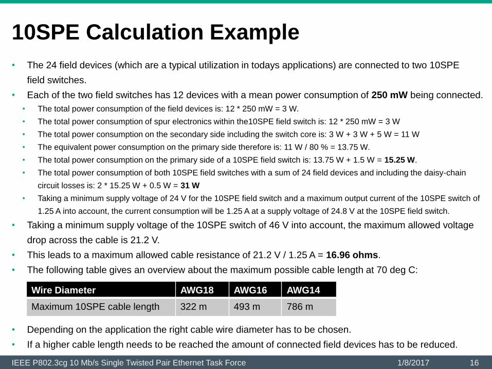
10SPE Calculation Example
• The 24 field devices (which are a typical utilization in todays applications) are connected to two 10SPE
field switches.
• Each of the two field switches has 12 devices with a mean power consumption of 250 mW being connected.
• The total power consumption of the field devices is: 12 * 250 mW = 3 W.
• The total power consumption of spur electronics within the10SPE field switch is: 12 * 250 mW = 3 W
• The total power consumption on the secondary side including the switch core is: 3 W + 3 W + 5 W = 11 W
• The equivalent power consumption on the primary side therefore is: 11 W / 80 % = 13.75 W.
• The total power consumption on the primary side of a 10SPE field switch is: 13.75 W + 1.5 W = 15.25 W.
• The total power consumption of both 10SPE field switches with a sum of 24 field devices and including the daisy-chain
circuit losses is: 2 * 15.25 W + 0.5 W = 31 W
• Taking a minimum supply voltage of 24 V for the 10SPE field switch and a maximum output current of the 10SPE switch of
1.25 A into account, the current consumption will be 1.25 A at a supply voltage of 24.8 V at the 10SPE field switch.
• Taking a minimum supply voltage of the 10SPE switch of 46 V into account, the maximum allowed voltage
drop across the cable is 21.2 V.
• This leads to a maximum allowed cable resistance of 21.2 V / 1.25 A = 16.96 ohms.
• The following table gives an overview about the maximum possible cable length at 70 deg C:
• Depending on the application the right cable wire diameter has to be chosen.
• If a higher cable length needs to be reached the amount of connected field devices has to be reduced.
IEEE P802.3cg 10 Mb/s Single Twisted Pair Ethernet Task Force 161/8/2017
Wire Diameter AWG18 AWG16 AWG14
Maximum 10SPE cable length 322 m 493 m 786 m

10SPE Calculation Example
• The calculations on the previous slide are done for a field switch, which can be used within hazardous
areas.
• For these applications it seems to make sense to limit the maximum supply voltage of a field switch to
48 V to keep the size and cost for the electronics in a reasonable range (e. g. thinking about encapsulation (Ex m) 10 %
safety margin have to be added to the supply voltage and additionally several components have to be utilized to 2/3 of their
rated values, which leads to 80 V types e. g. for power semiconductors and capacitors).
• A safe galvanic isolation within the field switch according to IEC/EN 60079-11 has to be implemented, which reduces the
possible efficiency of the power supply within the field switch.
• Additional safety circuits have to be added, which reduce the efficiency even further.
• Thinking about a field switch for non-hazardous applications, there is room for improvements.
• Taking a higher supply voltage into account (e. g. 57 V instead of 48 V) more energy could be provided to the field allowing
longer cable runs or more field devices.
• Having smaller isolation distances within the transformer improves the efficiency of the field switch power supply and
therefore reduces the losses within the field switch.
• Removing the additional safety circuits, will further increase the efficiency.
• Taking the same example setup into account, the power consumption for both field switches together could be reduced by
about 6 W in sum, while providing a 11.25 W higher supply power.
• This would allow a cable length of up to 1000 m using even a higher number of field devices.
• For shorter cable length providing a higher supply current would also allow to supply more field devices or field devices
with a higher power consumption.
• The given values should only be seen as an example. Depending on the specific application, there
could be different demands, for which other values could be more suitable.
IEEE P802.3cg 10 Mb/s Single Twisted Pair Ethernet Task Force 171/8/2017

10SPE Power Profile Ideas
• The following table shows one possible set of power profiles for a field switch (trunk port):
• The following table shows one possible set of power profiles for a field device (spur port):
• A field switch or field device should always support the maximum supply voltage of the
respective profile, the supply voltage range should be clearly marked on the device.
• It could make sense to add more profiles, depending on the application.
IEEE P802.3cg 10 Mb/s Single Twisted Pair Ethernet Task Force 181/8/2017
Profile Description
Non-powered For separately powered field switches
17.5 V, 0.38 A Not relevant for a field switch, but could make sense as a power
supply output, if only one field device should be supplied.
48 V, 1.25 A, tbd. For hazardous area field switches, Ex e port
57 V, 1.8 A, tbd. For non-hazardous area field switches, non-Ex
Profile Description
Non-powered For separately powered field devices
17.5 V, 0.38 A For low power field devices, Ex ia/ib port or non-Ex
48 V, 1.25 A, tbd. For high power field devices, Ex e port
57 V, 1.8 A, tbd. For high power field devices, non-Ex

1/8/2017IEEE P802.3cg 10 Mb/s Single Twisted Pair Ethernet Task Force 19
Thank You


![PERTEMUAN 3 MEDIA & KONEKTOR€¦ · [3] Media Kabel [a] Twisted Pair [i]. Unshielded Twisted Pair (UTP) [ii]. Shielded Twisted Pair (STP)](https://static.fdocuments.net/doc/165x107/612d4b2b1ecc515869421968/pertemuan-3-media-konektor-3-media-kabel-a-twisted-pair-i-unshielded.jpg)
![CFI 1 Twisted Pair 100 Mbit/s Ethernet (1TPCE)ieee802.org/3/cfi/0314_2/CFI_02_0314.pdfCFI 1 Twisted Pair 100 Mbit /s Ethernet (1TPCE) 1 Twisted Pair 100 [C] Mbit/s Ethernet Call for](https://static.fdocuments.net/doc/165x107/5ace48097f8b9a6c6c8ba026/cfi-1-twisted-pair-100-mbits-ethernet-1tpce-1-twisted-pair-100-mbit-s-ethernet.jpg)