1 Wireless and Mobile Network Architecture Chapter 2: Mobility Management Prof. Yuh-Shyan Chen...
65
1 Wireless and Mobile Network Architecture Chapter 2: Mobility Management Prof. Yuh-Shyan Chen Department of Computer Science and Information Engineering National Taipei University Sep. 2006
-
date post
21-Dec-2015 -
Category
Documents
-
view
231 -
download
4
Transcript of 1 Wireless and Mobile Network Architecture Chapter 2: Mobility Management Prof. Yuh-Shyan Chen...
1
Wireless and Mobile Network Architecture
Chapter 2: Mobility Management
Prof. Yuh-Shyan ChenDepartment of Computer Science
and Information Engineering National Taipei University
Sep. 2006

2
Outline
Introduction Handoff Roaming Management Roaming Management through SS7 Summary

3
Introduction
In the PCS system architecture (Fig. 2.1), the mobile service area is covered by a set of BSs which are responsible for relaying the call to/from the MSs
The BSs are connected to MSCs by land links.
MSC interfaces the MSs (via BSs) with the PSTN
4
Cont.
Two types of databases are used for roaming management Home Location Register (HLR) Visitor Location Register (VLR)
Examples of the protocols to support mobility management EIA/TIA Interim Standard 41 (IS-41 or ANSI-
41) GSM Mobile Application Part (MAP)

5
Fig. 2.1 A common PCS network architecture

6
Fig. 2.1 A common PCS network architecture
7
Two Aspects of Mobility in a PCS Network
Handoff (link transfer, or handover) When a mobile user is engaged in conversion, the
MS is connected to a BS via a radio link If the mobile user moves to the coverage area of
another BS, the radio link to the old BS is disconnected, and a radio link to the new BS should be established to continue the conversation
Roaming When a mobile user moves from one PCS system
(e.g., the system in Chiayi) to another (e.g., the system in Taipei), the system should be informed of the current location of the user

8
Three Strategies for Handoff Detection
Mobile-Controlled Handoff (MCHO) MCHO is used in DECT and PACS The MS continuously monitors the signal of
the surrounding BSs, The MS initiates the handoff process when
some handoff criteria are met. Network-Controlled Handoff (NCHO)
NCHO is used in CT-2 plus and AMPS The surrounding BSs measure the signal
from the MS The network initiates the handoff process
when some handoff criteria are met.

9
Cont.
Mobile-Assisted Handoff (MAHO) MAHO is used in GSM and IS-95 The network asks the MS to measure the
signal from the surrounding BSs, The network makes the handoff decision
based on reports from the MS
10
Inter-BS Handoff
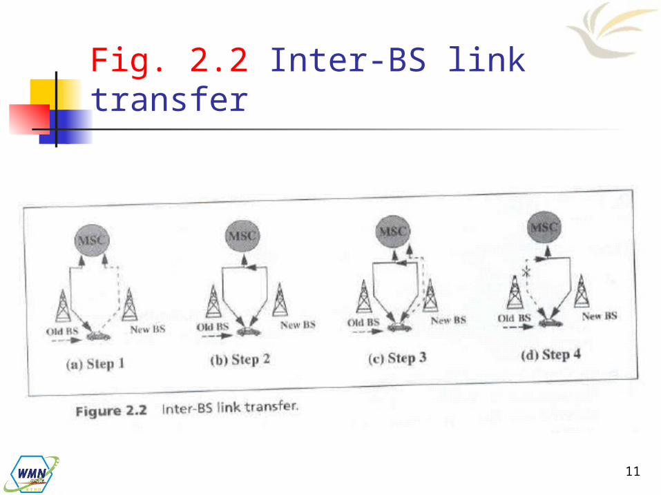
The new and old BSs are connected to the same MSC (Assumed that the need for handoff is detected by MS) The MS momentarily suspends
conversation and initiates the handoff procedure by signaling on an idle channel in the new BS. Then it resumes the conversation on the old BS. Fig. 2.2(a)
11
Fig. 2.2 Inter-BS link transfer
12
Cont.
Upon receipt of the signal, the MSC transfers the encryption information to the selected idle channel of the new BS and sets up the new conversation path to the MS through that channel. The switch bridges the new path with the old path and informs the MS to transfer from the old channel to the new channel.
Fig. 2.2(b)
13
Cont.
After the MS has been transferred to the new BS. It signals the network, and resumes conversation using the new channel
Fig. 2.2(c) Upon receipt of the handoff completion
signal, the network removes the bridge from the path and releases resources associated with the old channel.
Fig. 2.2(d)
14
Cont.
For NCHO, all handoff signaling messages are exchanged between the MS and the old BS through the failing link. Thus, the whole process must be completed as quickly as possible.
If the new BS does not have an idle channel, the handoff call may be dropped (forced to terminate).
Forced termination of an ongoing call is considered less desirable than blocking a new call attempt.

15
Channel Assignment Schemes for Handoff Calls
Nonprioritized Scheme The networks handle a handoff in the
same manner as a new call attempt
Reserved Channel Scheme Similar to the nonprioritized scheme,
except that some channels in each BS are reserved for handoff calls
16
Cont.
Queuing Priority Scheme Based on the fact that adjacent coverage
areas of BSs overlap There is a considerable area where a call can
be handled by either BS, which is called the handoff area
If no new channel is available in the new BS during handoff, the new BS buffers the handoff request in a waiting queue.
The MS continues to use the channel with the old BS until either a channel in the new BS becomes available
17
Cont. Subrating Scheme
The new BS creates a new channel for a handoff call by sharing resources with an existing call if no free channel is available.
Subrating means an occupied full-rate channel is temporarily divided into two channels at half the original rate.
One half-rate channel is to server the exiting call, and the other half-rate channel is to serve the handoff request
When occupied channels are released, the subrated channels are immediately switched back to the full rate channels.
18
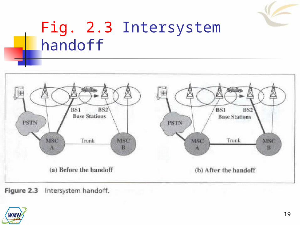
2.1.2 Intersystem Handoff
Step 1 MSC A requests a MSC B to perform
handoff measurements on the call in progress.
MSC then selects a candidate BS, BS2, and interrogates it for signal quality parameters.
MSC B returns the signal quality parameters, along with other relevant information, to MSC A.
19
Fig. 2.3 Intersystem handoff
20
Cont.
Step 2 MSC A checks if the MS has made too many
handoffs recently (e,g,, to avoid that MS is moving within overlapped area) or if intersystem trunks are not available.
If so, MSC A exists the procedure Otherwise, MSC A asks MSC B to set up a
voice channels.
21
Cont.
Step 3 MSC A sends the MS a handoff order The MS synchronizes to BS 2. After the MS is connected to BS 2, MSC B
informs MSC A that the handoff is successful.
MSC A is referred to as the anchor MSC, and is always in the call path before and after the handoff.

22
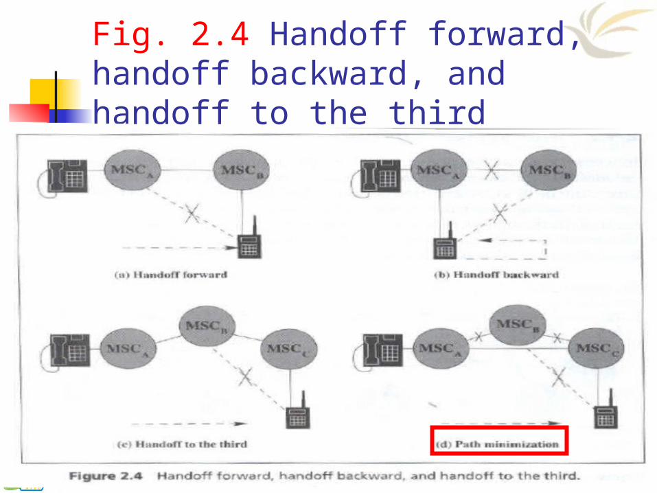
Anchor Approach
If the MS moves back to MSC A again, the connection between MSC A and MSC B is removed.
If the MS moves to the third MSC C, the MSC B will be in the call path.
Path Minimization When the MS moves to the third MSC, the
second MSC may be removed from the call path
The link between MSC A and MSC B is disconnected, and MSC C is connected MSC A directly.
23
Fig. 2.4 Handoff forward, handoff backward, and handoff to the third

24
2.2 Roaming Management Two basic operations in roaming
management are Registration (or Location Update)
The process whereby an MS informs the system of its current location
Location Tracking The process during which the system locates
the MS (this process is required when the network attempts to deliver a call to the mobile user)
25
Cont.
The roaming management schemes proposed in IS-41 and GSM MAP are two-level strategies
They use a two-tier system of home and visited databases that are Home Location Register (HLR). Visited Location Register (VLR).
26
Home Location Register (HLR)
When a user subscribes to the services of a PCS network, a record is created in the system’s database Which is referred as to the home system
of the mobile user. HLR is a network database that stores
and manages all subscriptions of a specified operator.

27
Cont.
The information contained in HLR includes MS identity Directory number Profile information Current location Validation period

28
Visitor Location Register (VLR)
When the mobile user visits a PCS network other than the home system, a temporary record for the mobile user is created in the visitor location register (VLR) of the visited system.
The VLR temporarily stores subscription information for the visiting subscribers.
29
Cont.
The MSC (corresponding with the VLR) can provide service to the mobile user.
The VLR is the “other” location register used to retrieve information for handling calls to/from a visiting mobile users.

30
MS Registration Process (Fig. 2.5)
Step 1 Suppose that the home system of a mobile
user is in Morristown. When the mobile user moves from one visited system (e.g., New York City) to another (e.g., Los Angeles), it must register in the VLR of the new visited system.
Step 2 The new VLR informs the mobile user’s HLR
of the person’s current location (the address of the new VLR)
The HLR sends an ACK., which includes the MS’s profile, to the new VLR

31
Fig. 2.5 MS registration process
32
Cont.
Step 3 The new VLR informs the MS of the
successful registration. Step 4
After Step 2, the HLR also sends a deregistration message to cancel the obsolete location record of the MS in the old VLR.
The old VLR acknowledges the deregistration.

33
Call Origination Procedure
To originate a call, the MS executes the following steps. MS contacts the MSC in the visited PCS
network. The call request is forwarded to the VLR
for approval. If the call is accepted, the MSC sets up the
call to the called party following the standard PSTN call setup procedure.

34
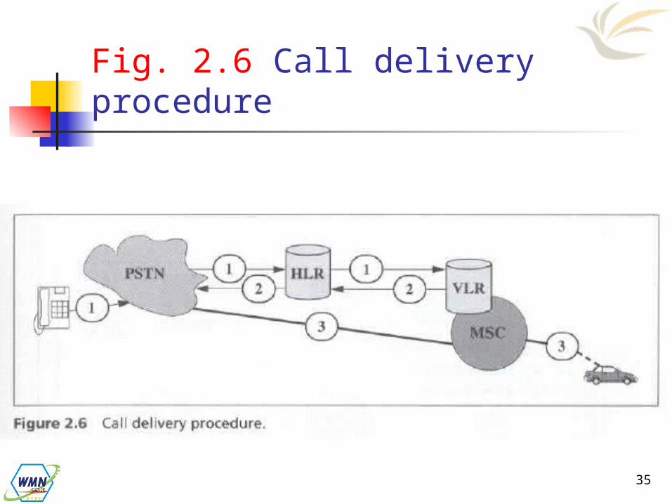
Call Delivery (Call Termination/Location Tracking) (Fig. 2.6)
Step 1 If a wireline phone attempts to call a
mobile subscriber, the call is forwarded to a switch, called the originating switch in the PSTN.
The originating switch queries the HLR to find the current VLR of the MS.
The HLR queries the VLR in the which the MS resides to get a routable address.
35
Fig. 2.6 Call delivery procedure
36
Cont.
Note that, if the originating switch is not capable of querying the HLR (i.e., it is not equipped to support mobility), the call is routed through the PSTN to the subscriber’s Gateway MSC, which queries the HLR to determine the current VLR serving the MS.
Step 2 The VLR returns the routable address to the
originating switch through HLR. Step 3
Based on the routable address, a trunk (voice circuit) is set up from the originating switch to the MS through the visited MSC.
37
Roaming Management under SS7
How is mobile roaming managed by the PSTN signaling By using SS7.
Signaling System No. 7 (SS 7) is a Common Channel Signaling (CCS) system.
38
Cont.
SS7 is developed to satisfy the telephone operating companies’ requirement for an improvement to the earlier signaling systems, which is lacked the sophistication required to deliver mush more than plain old telephone service (POTS).
Signaling between a PCS network and the PSTN are typically achieved by the SS7 network.

39
Common Channel Signaling (CCS)
CCS is a out-of-band signaling network that provides control and management functions in the telephone network.
CCS consists of Supervisory functions Addressing Call Information Provisioning

40
Cont.
Functions provided by CCS are To convey messages to initiate and
terminate calls To determine the status of some part of
the network To control the amount of traffic allowed

41
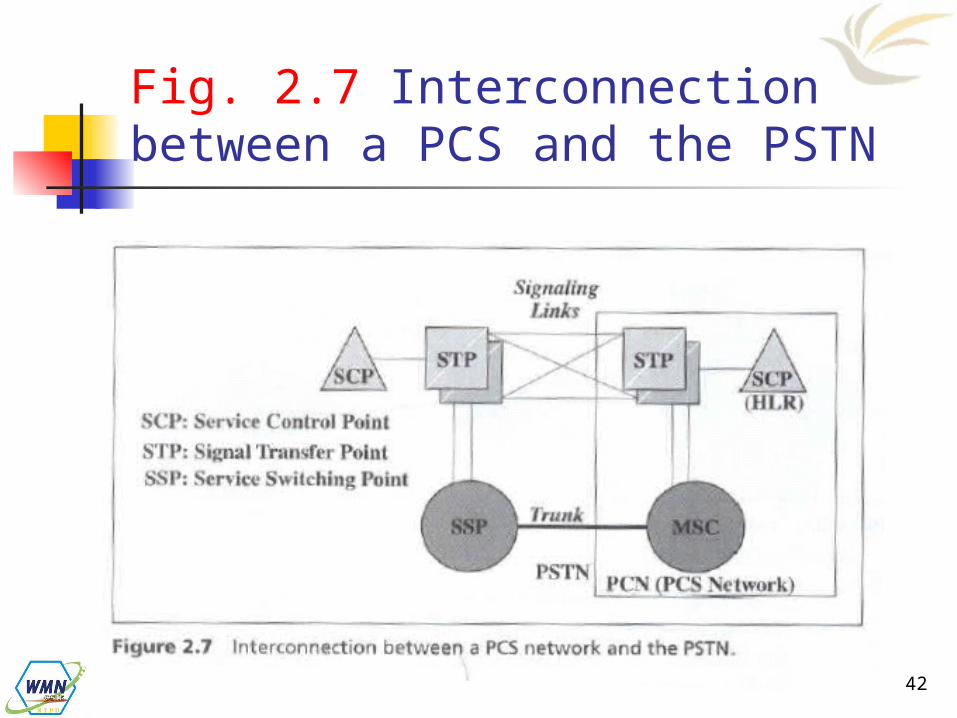
Three Distinct Components of SS7 (Fig. 2.7)
Service Switching Point (SSP) A telephone switch interconnected by SS7
links. The SSPs perform call processing on calls
that originate, tandem, or terminate at that nodes.
A local SSP in the PSTN can be central or end office (EO).
An SSP in a PCS network is called a mobile switching center (MSC).
42
Fig. 2.7 Interconnection between a PCS and the PSTN
43
Cont.
Signal Transfer Point (STP) A switch that reply SS7 message between
network switched and databases Based on the address fields of the SS7
messages, the STPs route the message to the correct out-going signal links.
For the reliability requirements, STPs are provisioned in mated pairs.
44
Cont.
Service Control Point (SCP) SCP contains databases for providing
enhanced services. An SCP accepts queries from an SSP and
returns the requested information to the SSP.
In mobile applications, an SCP may contains an HLR or VLR.
In SS7 network, the trunks (voice circuits) connects SSPs to carry user data/voice information.

45
Cont.
The signaling links connects SCPs to STPs, and STPs to SSPs.
The SSPs and SCPs are connected indirectly through STPs.

46
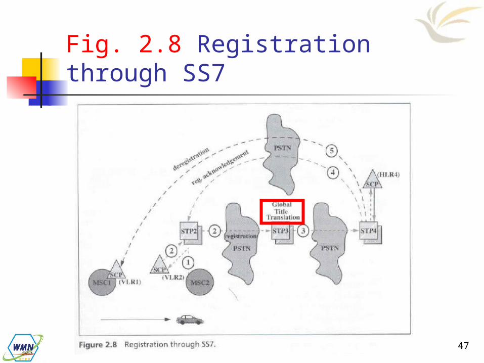
Registration through SS7
Example: the MS moves from VLR1 to VLR2.
Step 1 The MS enters the area controlled by MSC2. MSC 2 lunches a registration query to its
VLR through STP2, assuming that VLR2 and MSC2 are not co-located.
Step 2 VLR2 sends a registration message to the
MS’s HLR (HLR4).
47
Fig. 2.8 Registration through SS7

48
Cont.
VLR2 may not know the actual address of HLR. Instead, VLR2 sends the message to containing the MS identity, called Mobile Identification Number (MIN), to an STP (STP3) that can translate the MIN into the HLR address.
Step 3 The MIN-to-HLR address translation is
performed at STP3 by a table-lookup technique called Global Title Translation (GTT). STP3 the forwards the registration message to HLR.

49
Cont.
Step 4 After the registration, HLR sends an
acknowledgement back to VLR2. Since the address of VLR2 is known, the acknowledgement may be sent to VLR2 using a shortcut, without passing through STP3.
Step 5 After Step 3, HLR sends a deregistration
message to VLR1 to cancel the obsolete record. VLR1 then acknowledges the cancellation.
50
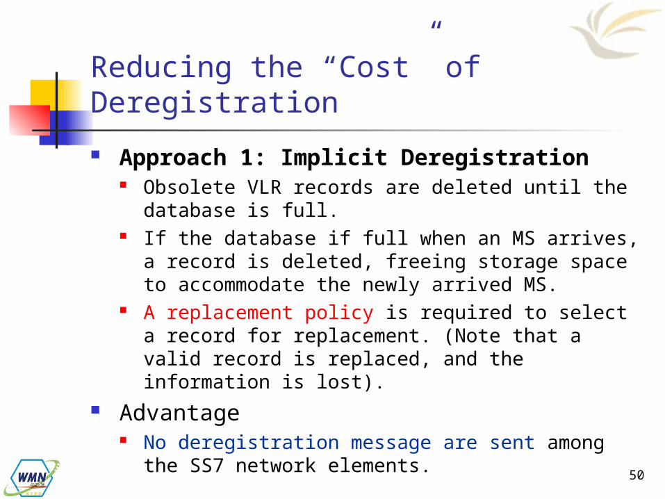
Reducing the “Cost” of Deregistration
Approach 1: Implicit Deregistration Obsolete VLR records are deleted until the
database is full. If the database if full when an MS arrives, a
record is deleted, freeing storage space to accommodate the newly arrived MS.
A replacement policy is required to select a record for replacement. (Note that a valid record is replaced, and the information is lost).
Advantage No deregistration message are sent among
the SS7 network elements.

51
Cont.
Approach 2: Periodic Re-registration. The MS periodically re-registers to the VLR. If the VLR does not receive the re-
registration message within a timeout period, the record is deleted
Advantage This approach only creates local message
traffic between the MSC and the VLR. No SS7 messages are generated if the VLR
is co-located with the MSC.

52
Reducing the Registration Traffic – Pointer Forwarding Scheme
Move Operation (registration) When an MS moves from one VLR to
another, a pointer is created from the old VLR to the new VLR.
No registration to the HLR is required.
Find Operation (call delivery) When the HLR attempts to locate the MS
for call delivery, the pointer chain is traced.
After the find operation, the HLR points directly to the destination VLR.

53
Fig. 2.9 Pointer forwarding scheme
54
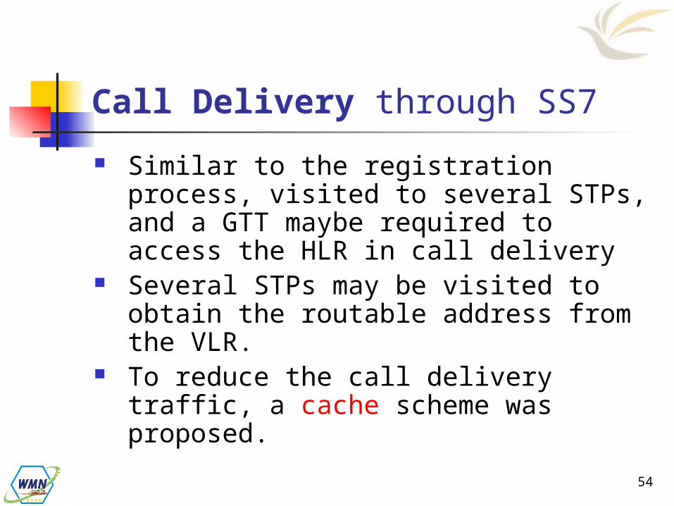
Call Delivery through SS7
Similar to the registration process, visited to several STPs, and a GTT maybe required to access the HLR in call delivery
Several STPs may be visited to obtain the routable address from the VLR.
To reduce the call delivery traffic, a cache scheme was proposed.

55
Fig. 2.10 Call delivery through SS7
56
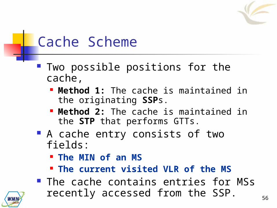
Cache Scheme
Two possible positions for the cache, Method 1: The cache is maintained in the
originating SSPs. Method 2: The cache is maintained in the
STP that performs GTTs. A cache entry consists of two fields:
The MIN of an MS The current visited VLR of the MS
The cache contains entries for MSs recently accessed from the SSP.
57
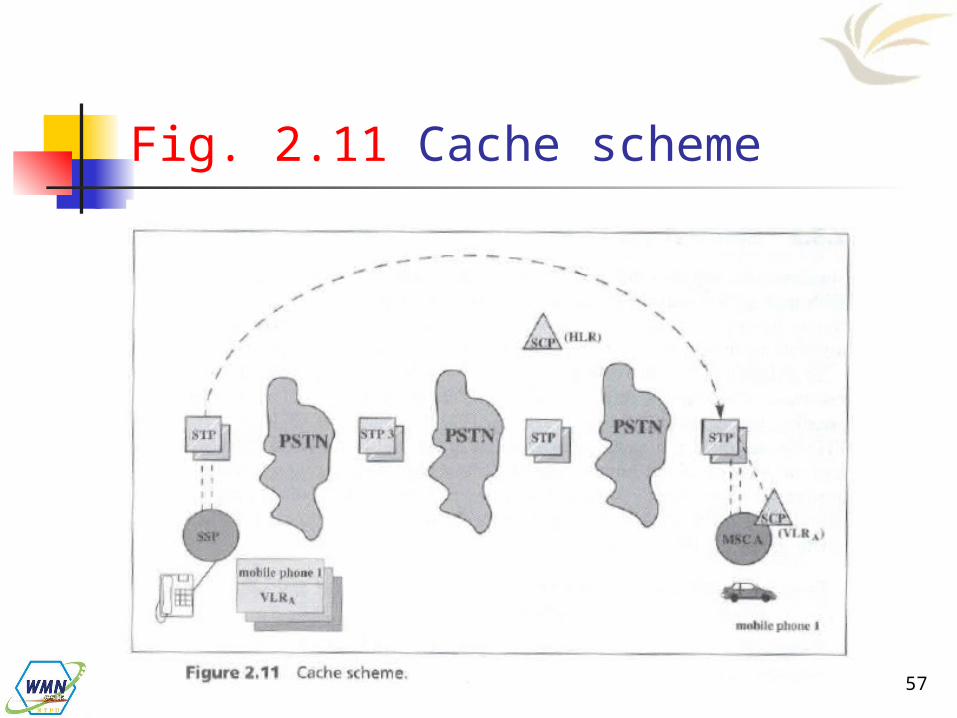
Fig. 2.11 Cache scheme
58
Cont.
When the calling party originates a call to an MS, the SSP first checks if the cache entry for the MS exists. Three possibilities are Case 1: The cache entry does not exists
The call delivery is processed following the normal procedure.
Case 2: The cache entry exists and is current
The VLR is directly accessed.

59
Cont.
Case 3: The cache entry exists but is obsolete
Then procedure detects that the cache entry is obsolete if the queried VLR’s response is negative. The normal procedure is executed.
60
2.4 Roaming Management for CT2
In a public environment, CT2 is a one-way calling PCS system A CT2 handset can originate calls, but
cannot receive incoming calls.
To construct two-way calling mechanism into CT2
61
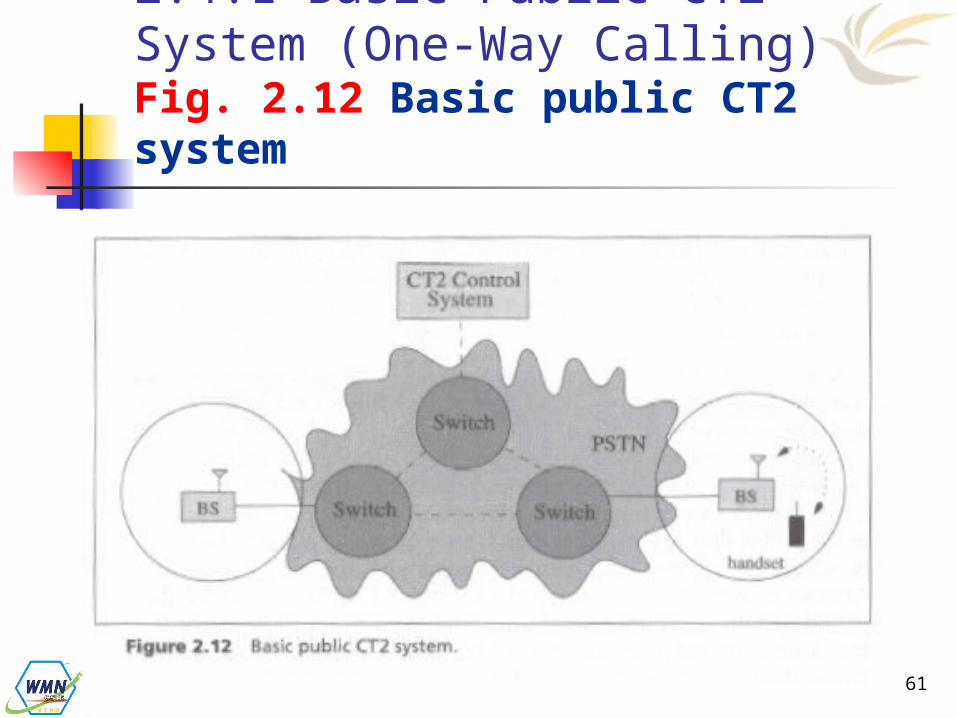
2.4.1 Basic Public CT2 System (One-Way Calling) Fig. 2.12 Basic public CT2 system
62
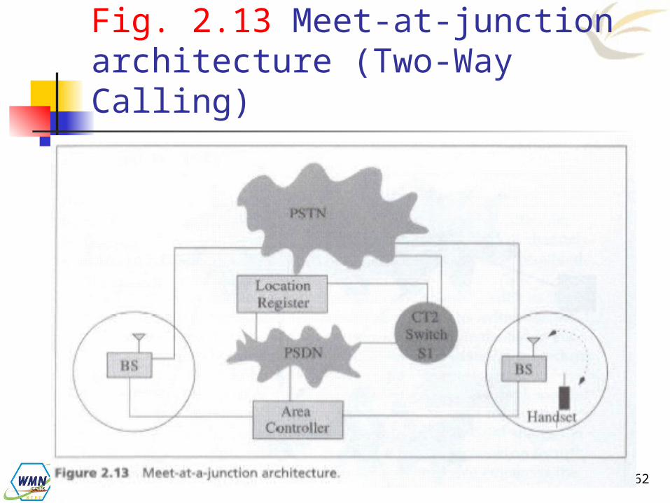
Fig. 2.13 Meet-at-junction architecture (Two-Way Calling)

63
Fig. 2.14 CT2 call delivery procedure

64
Call Delivery Procedure
Step 1 When the calling party dials the number of a
CT2 handset, a voice trunk is set up from the originating switch to the CT2 switch S1.
Step 2 S1 queries the location register to identify
the area controller of the handset.
65
Cont. Step 3
An alerting message is sent from S1 to the corresponding area controller via the PSDN.
The area controller then broadcasts the alerting message to the connected BSs to page the handset.
Step 4 If the handset responds, the corresponding
base station redials to S1 through PSTN. Step 5.
S1 bridges the two trunks, and the conversation begins.