This episode takes 10 to 15 minutes Just click on the arrows to proceed >>
Upload
arthur-conrad-evansCategory
view
215download
0
1
What is the most boring household activity?

2
A relevant question
Assuming you’ve got:—One washer (takes 30 minutes)
—One drier (takes 40 minutes)
—One “folder” (takes 20 minutes)
It takes 90 minutes to wash, dry, and fold 1 load of laundry.—How long does 4 loads take?

3
The slow way
If each load is done sequentially it takes 6 hours
30 40 20 30 40 20 30 40 20 30 40 20
6 PM 7 8 9 10 11 Midnight
Time

4
Laundry Pipelining
Start each load as soon as possible— Overlap loads
Pipelined laundry takes 3.5 hours
6 PM 7 8 9 10 11 Midnight
Time
30 40 40 40 40 20

5
Pipelining Lessons
Pipelining doesn’t help latency of single load, it helps throughput of entire workload
Pipeline rate limited by slowest pipeline stage
Multiple tasks operating simultaneously using different resources
Potential speedup = Number pipe stages
Unbalanced lengths of pipe stages reduces speedup
Time to “fill” pipeline and time to “drain” it reduces speedup
6 PM 7 8 9
Time
30 40 40 40 40 20

6
Pipelining
Pipelining is a general-purpose efficiency technique— It is not specific to processors
Pipelining is used in:— Assembly lines— Bucket brigades— Fast food restaurants
Pipelining is used in other CS disciplines:— Networking— Server software architecture
Useful to increase throughput in the presence of long latency— More on that later…

7
Pipelining Processors
We’ve seen two possible implementations of the MIPS architecture.—A single-cycle datapath executes each instruction in just one
clock cycle, but the cycle time may be very long.—A multicycle datapath has much shorter cycle times, but each
instruction requires many cycles to execute. Pipelining gives the best of both worlds and is used in just about
every modern processor.—Cycle times are short so clock rates are high.—But we can still execute an instruction in about one clock
cycle!Single Cycle Datapath CPI = 1 Long Cycle Time
Multi-cycle Datapath CPI = ~4 Short Cycle Time
Pipelined Datapath CPI = ~1 Short Cycle Time

8
Instruction execution review
Executing a MIPS instruction can take up to five steps.
However, as we saw, not all instructions need all five steps.
Step Name
Description
Instruction Fetch IF Read an instruction from memory.
Instruction Decode
ID Read source registers and generate control signals.
Execute EX Compute an R-type result or a branch outcome.
Memory MEM Read or write the data memory.
Writeback WB Store a result in the destination register.Instructio
nSteps required
beq IF ID EX
R-type IF ID EX WB
sw IF ID EX MEM
lw IF ID EX MEM WB

9
Single-cycle datapath diagram
4
Shiftleft 2
PCAdd
Add
0
Mux
1
PCSrc
Readaddress
Writeaddress
Writedata
Datamemory
Readdata
MemWrite
MemRead
1
Mux
0
MemToRegReadaddress
Instructionmemory
Instruction[31-0]
I [15 - 0]
I [25 - 21]
I [20 - 16]
I [15 - 11]
0
Mux
1
RegDst
Readregister 1
Readregister 2
Writeregister
Writedata
Readdata 2
Readdata 1
Registers
RegWrite
Signextend
0
Mux
1
ALUSrc
Result
ZeroALU
ALUOp2ns
2ns2ns
1ns
How long does it take to execute each instruction?

11
Example: Instruction Fetch (IF)
Readaddress
Instructionmemory
Instruction[31-0]
Readaddress
Writeaddress
Writedata
Datamemory
Readdata
MemWrite
MemRead
1
Mux
0
MemToReg
Signextend
0
Mux
1
ALUSrc
Result
ZeroALU
ALUOp
I [15 - 0]
I [25 - 21]
I [20 - 16]
I [15 - 11]
0
Mux
1
RegDst
Readregister 1
Readregister 2
Writeregister
Writedata
Readdata 2
Readdata 1
Registers
RegWrite
Let’s quickly review how lw is executed in the single-cycle datapath.
We’ll ignore PC incrementing and branching for now. In the Instruction Fetch (IF) step, we read the instruction memory.

12
Instruction Decode (ID)
Readaddress
Instructionmemory
Instruction[31-0]
Readaddress
Writeaddress
Writedata
Datamemory
Readdata
MemWrite
MemRead
1
Mux
0
MemToReg
Signextend
0
Mux
1
ALUSrc
Result
ZeroALU
ALUOp
I [15 - 0]
I [25 - 21]
I [20 - 16]
I [15 - 11]
0
Mux
1
RegDst
Readregister 1
Readregister 2
Writeregister
Writedata
Readdata 2
Readdata 1
Registers
RegWrite
The Instruction Decode (ID) step reads the source register from the register file.
13
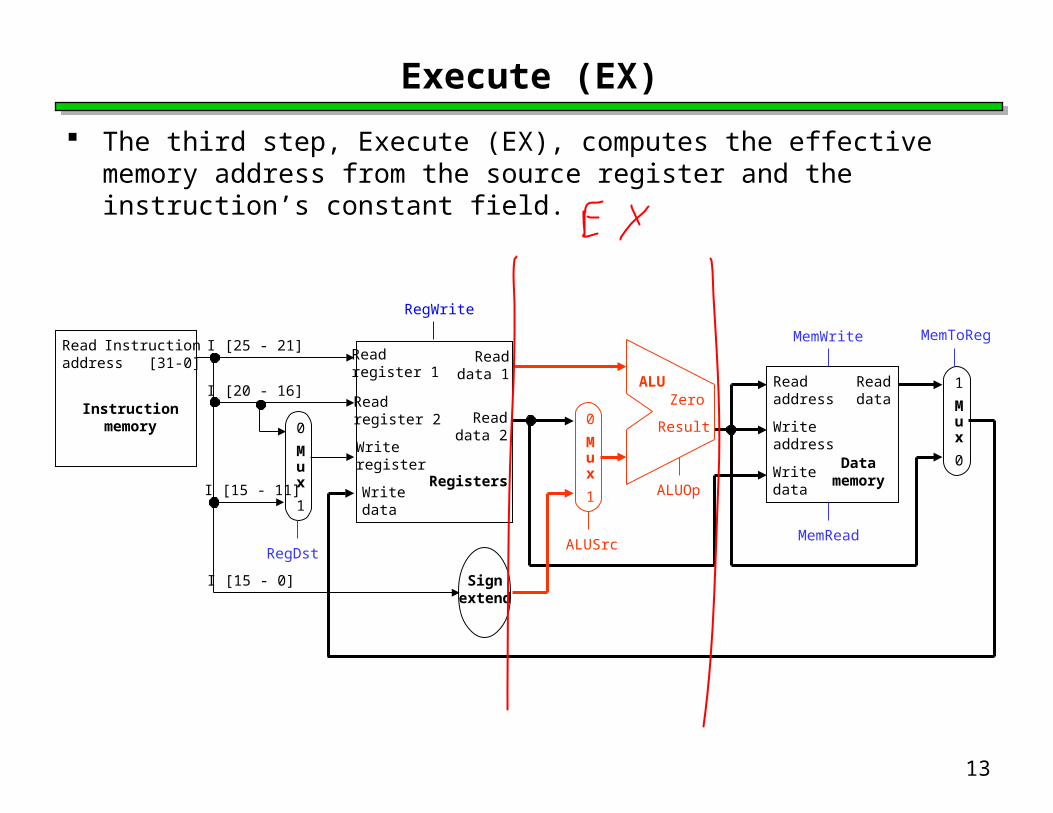
Execute (EX)
Readaddress
Instructionmemory
Instruction[31-0]
Readaddress
Writeaddress
Writedata
Datamemory
Readdata
MemWrite
MemRead
1
Mux
0
MemToReg
Signextend
0
Mux
1
ALUSrc
Result
ZeroALU
ALUOp
I [15 - 0]
I [25 - 21]
I [20 - 16]
I [15 - 11]
0
Mux
1
RegDst
Readregister 1
Readregister 2
Writeregister
Writedata
Readdata 2
Readdata 1
Registers
RegWrite
The third step, Execute (EX), computes the effective memory address from the source register and the instruction’s constant field.

14
Memory (MEM)
Readaddress
Instructionmemory
Instruction[31-0]
Readaddress
Writeaddress
Writedata
Datamemory
Readdata
MemWrite
MemRead
1
Mux
0
MemToReg
Signextend
0
Mux
1
ALUSrc
Result
ZeroALU
ALUOp
I [15 - 0]
I [25 - 21]
I [20 - 16]
I [15 - 11]
0
Mux
1
RegDst
Readregister 1
Readregister 2
Writeregister
Writedata
Readdata 2
Readdata 1
Registers
RegWrite
The Memory (MEM) step involves reading the data memory, from the address computed by the ALU.

15
Writeback (WB)
Readaddress
Instructionmemory
Instruction[31-0]
Readaddress
Writeaddress
Writedata
Datamemory
Readdata
MemWrite
MemRead
1
Mux
0
MemToReg
Signextend
0
Mux
1
ALUSrc
Result
ZeroALU
ALUOp
I [15 - 0]
I [25 - 21]
I [20 - 16]
I [15 - 11]
0
Mux
1
RegDst
Readregister 1
Readregister 2
Writeregister
Writedata
Readdata 2
Readdata 1
Registers
RegWrite
Finally, in the Writeback (WB) step, the memory value is stored into the destination register.

16
A bunch of lazy functional units
Notice that each execution step uses a different functional unit. In other words, the main units are idle for most of the 8ns cycle!
—The instruction RAM is used for just 2ns at the start of the cycle.
—Registers are read once in ID (1ns), and written once in WB (1ns).
—The ALU is used for 2ns near the middle of the cycle.—Reading the data memory only takes 2ns as well.
That’s a lot of hardware sitting around doing nothing.

17
Putting those slackers to work
We shouldn’t have to wait for the entire instruction to complete before we can re-use the functional units.
For example, the instruction memory is free in the Instruction Decode step as shown below, so...
Readaddress
Instructionmemory
Instruction[31-0]
Readaddress
Writeaddress
Writedata
Datamemory
Readdata
MemWrite
MemRead
1
Mux
0
MemToReg
Signextend
0
Mux
1
ALUSrc
Result
ZeroALU
ALUOp
I [15 - 0]
I [25 - 21]
I [20 - 16]
I [15 - 11]
0
Mux
1
RegDst
Readregister 1
Readregister 2
Writeregister
Writedata
Readdata 2
Readdata 1
Registers
RegWrite
Instruction Decode (ID)Idle
18
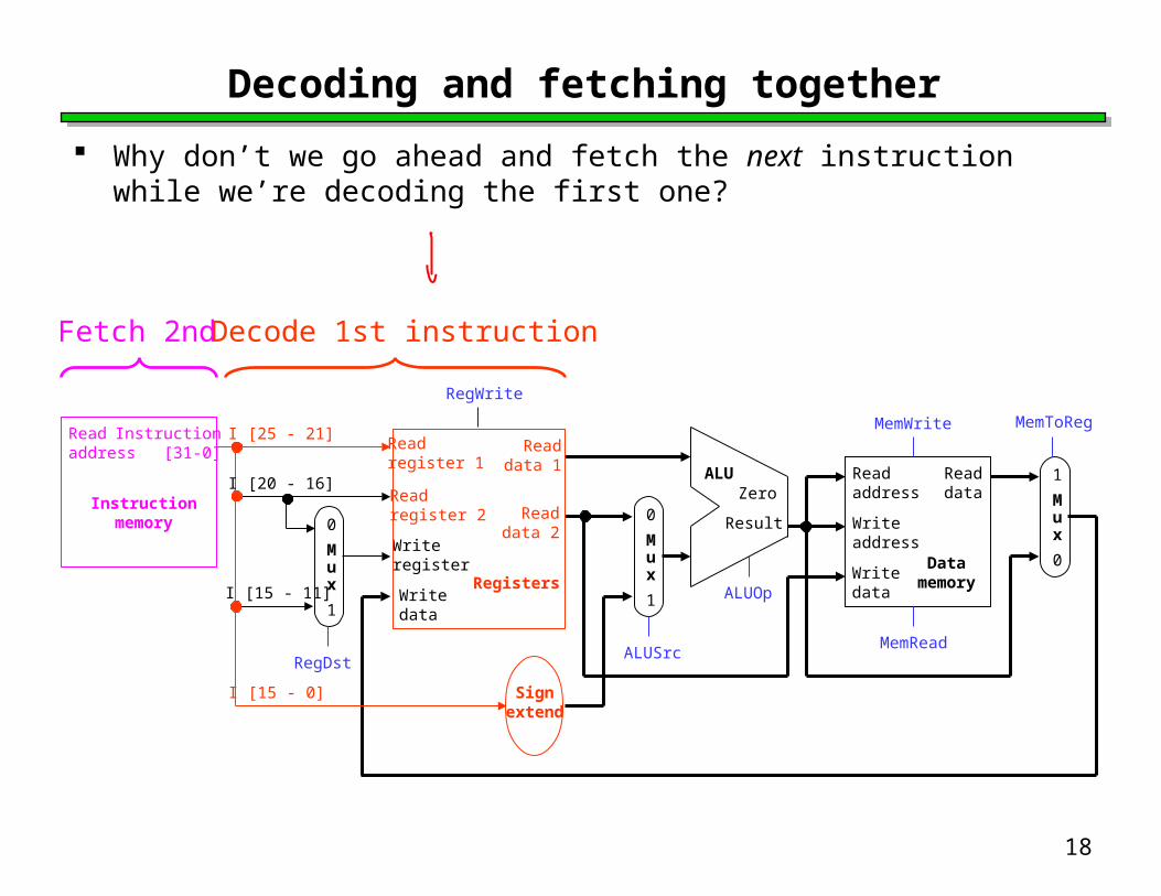
Decoding and fetching together
Why don’t we go ahead and fetch the next instruction while we’re decoding the first one?
Instructionmemory
Instruction[31-0]
Readaddress
Writeaddress
Writedata
Datamemory
Readdata
MemWrite
MemRead
1
Mux
0
MemToReg
Signextend
0
Mux
1
ALUSrc
Result
ZeroALU
ALUOp
I [15 - 0]
I [25 - 21]
I [20 - 16]
I [15 - 11]
0
Mux
1
RegDst
Readregister 1
Readregister 2
Writeregister
Writedata
Readdata 2
Readdata 1
Registers
RegWrite
Readaddress
Decode 1st instructionFetch 2nd

19
Executing, decoding and fetching
Similarly, once the first instruction enters its Execute stage, we can go ahead and decode the second instruction.
But now the instruction memory is free again, so we can fetch the third instruction!
Readaddress
Instructionmemory
Instruction[31-0]
Readaddress
Writeaddress
Writedata
Datamemory
Readdata
MemWrite
MemRead
1
Mux
0
MemToReg
Signextend
0
Mux
1
ALUSrc
Result
ZeroALU
ALUOp
I [15 - 0]
I [25 - 21]
I [20 - 16]
I [15 - 11]
0
Mux
1
RegDst
Readregister 1
Readregister 2
Writeregister
Writedata
Readdata 2
Readdata 1
Registers
RegWrite
Decode 2ndFetch 3rd
Execute 1st

20
Making Pipelining Work
We’ll make our pipeline 5 stages long, to handle load instructions as they were handled in the multi-cycle implementation—Stages are: IF, ID, EX, MEM, and WB
We want to support executing 5 instructions simultaneously: one in each stage.

21
Break datapath into 5 stages
Each stage has its own functional units. Each stage can execute in 2ns
—Just like the multi-cycle implementation
Readaddress
Instructionmemory
Instruction[31-0]
Readaddress
Writeaddress
Writedata
Datamemory
Readdata
MemWrite
MemRead
1
Mux
0
MemToReg
Signextend
0
Mux
1
ALUSrc
Result
ZeroALU
ALUOp
I [15 - 0]
I [25 - 21]
I [20 - 16]
I [15 - 11]
0
Mux
1
RegDst
Readregister 1
Readregister 2
Writeregister
Writedata
Readdata 2
Readdata 1
Registers
RegWrite
IDIF EXE MEM WB
2ns 2ns 2ns2ns

22
Pipelining Loads
6 PM 7 8 9Time
30 40 40 40 40 20
Clock cycle1 2 3 4 5 6 7 8 9
lw $t0, 4($sp) IF ID EX MEM WBlw $t1, 8($sp) IF ID EX ME
MWB
lw $t2, 12($sp) IF ID EX MEM
WB
lw $t3, 16($sp) IF ID EX MEM WBlw $t4, 20($sp) IF ID EX MEM WB

25
Pipelining Performance
Execution time on ideal pipeline:—time to fill the pipeline + one cycle per instruction—What is the execution time for N instructions?
Compare with other implementations:—Single Cycle: (8ns clock period)
How much faster is pipelining for N=1000 ?
Clock cycle1 2 3 4 5 6 7 8 9
lw $t0, 4($sp) IF ID EX MEM WBlw $t1, 8($sp) IF ID EX ME
MWB
lw $t2, 12($sp) IF ID EX MEM
WB
lw $t3, 16($sp) IF ID EX MEM WBlw $t4, 20($sp) IF ID EX MEM WB
filling

26
Pipeline Datapath: Resource Requirements
Clock cycle1 2 3 4 5 6 7 8 9
lw $t0, 4($sp) IF ID EX MEM WBlw $t1, 8($sp) IF ID EX ME
MWB
lw $t2, 12($sp) IF ID EX MEM
WB
lw $t3, 16($sp) IF ID EX MEM WBlw $t4, 20($sp) IF ID EX MEM WB We need to perform several operations in the same cycle.
— Increment the PC and add registers at the same time. — Fetch one instruction while another one reads or writes data.
What does this mean for our hardware?

27
Pipelining other instruction types
R-type instructions only require 4 stages: IF, ID, EX, and WB—We don’t need the MEM stage
What happens if we try to pipeline loads with R-type instructions?
Clock cycle1 2 3 4 5 6 7 8 9
add $sp, $sp, -4 IF ID EX WBsub $v0, $a0, $a1
IF ID EX WB
lw $t0, 4($sp) IF ID EX MEM
WB
or $s0, $s1, $s2
IF ID EX WB
lw $t1, 8($sp) IF ID EX MEM WB

28
Important Observation
Each functional unit can only be used once per instruction Each functional unit must be used at the same stage for all
instructions. See the problem if:—Load uses Register File’s Write Port during its 5th stage—R-type uses Register File’s Write Port during its 4th stage
Clock cycle1 2 3 4 5 6 7 8 9
add $sp, $sp, -4 IF ID EX WBsub $v0, $a0, $a1
IF ID EX WB
lw $t0, 4($sp) IF ID EX MEM
WB
or $s0, $s1, $s2
IF ID EX WB
lw $t1, 8($sp) IF ID EX MEM WB

29
A solution: Insert NOP stages
Enforce uniformity —Make all instructions take 5 cycles.—Make them have the same stages, in the same order
• Some stages will do nothing for some instructions
• Stores and Branches have NOP stages, too…
Clock cycle1 2 3 4 5 6 7 8 9
add $sp, $sp, -4 IF ID EX NOP WBsub $v0, $a0, $a1
IF ID EX NOP WB
lw $t0, 4($sp) IF ID EX MEM
WB
or $s0, $s1, $s2
IF ID EX NOP WB
lw $t1, 8($sp) IF ID EX MEM WB
R-type IF ID EX NOP WB
store IF ID EX MEM NOP
branch IF ID EX NOP NOP

30
Summary
Pipelining attempts to maximize instruction throughput by overlapping the execution of multiple instructions.
Pipelining offers amazing speedup.—In the best case, one instruction finishes on every cycle, and
the speedup is equal to the pipeline depth. The pipeline datapath is much like the single-cycle one, but with
added pipeline registers—Each stage needs is own functional units
Next time we’ll see the datapath and control, and walk through an example execution.