
meltrade.humeltrade.hu/download.php?f=3393-mccb-technical-notes-y... · 1 We have the pleasure of...
76
MOULDED CASE CIRCUIT BREAKERS TECHNICAL NOTES
Transcript of meltrade.humeltrade.hu/download.php?f=3393-mccb-technical-notes-y... · 1 We have the pleasure of...

MOULDED CASE CIRCUIT BREAKERS
TECHNICAL NOTES

1
We have the pleasure of providing all our customers with the technical information for Mitsubishi
moulded case circuit breakers. This indicates the fundamental data of our circuit breakers
regarding the applicable standards, constructional principles, and operational performances.
Please refer to the catalogue of our circuit breakers for details of specifications.
Also please stand in need of the handling and maintenance manual for maintaning the circuit
breakers in service continuously.
We do hope they are available for all our customers to built more efficient systems.
1. INTRODUCTION ............................................... 2
2. FEATURES ....................................................... 32.1 PA Auto-Puffer ................................................... 32.2 JPT ...................................................................... 32.3 Shunt-less .......................................................... 32.4 Advanced ISTAC................................................ 42.5 Equipment of High Technology ....................... 4
3. CONSTRUCTION AND OPERATION............... 6
4. CHARACTERISTICS ANDPERFORMANCE............................................. 114.1 Overcurrent-Trip Characteristics ................... 114.2 Short-Circuit Trip Characteristics .................. 114.3 Effects of Mounting Attitudes ........................ 124.4 DC Tripping Characteristics of AC-Rated
MCCBs .............................................................. 124.5 Frequency Characteristics ............................. 124.6 Switching Characteristics ............................... 134.7 Dielectric Strength........................................... 13
5. CIRCUIT BREAKER SELECTION .................. 145.1 Circuit Breaker Selection Table ..................... 14
6. PROTECTIVE CO-ORDINATION ................... 346.1 General ............................................................. 346.2 Interrupting Capacity Consideration ............. 356.3 Selective-Interruption...................................... 366.4 Cascade Back-up Protection .......................... 416.5 I2t Let-Through and Current Limiting
Characteristics................................................. 43
6.6 Protective Coordination with Wiring ............. 456.7 Protective Coordination with
Motor Starters .................................................. 486.8 Coordination with Devices on the
High-Voltage Circuit ........................................ 50
7. SELECTION .................................................... 537.1 Motor Branch Circuits ..................................... 537.2 For Lighting and Heating Branch Circuits .... 537.3 For Main Circuits ............................................. 547.4 For Welding Circuits ....................................... 547.5 MCCBs for Transformer-Primary Use............ 567.6 MCCBs for Use in Capacitor ........................... 577.7 MCCBs for Thyristor Circuits ......................... 587.8 Selection of MCCBs in inverter circuit .......... 64
8. ENVIRONMENTAL CHARACTERISTICS ...... 668.1 Atmospheric Environment.............................. 668.2 Vibration-Withstand Characteristics ............. 678.3 Shock-Withstand Characteristics .................. 68
9. SHORT-CIRCUIT CURRENTCALCULATIONS ............................................ 699.1 Purpose ............................................................ 699.2 Definitions ........................................................ 699.3 Impedances and Equivalent Circuits of
Circuit Components ........................................ 699.4 Classification of Short-Circuit Current .......... 729.5 Calculation Procedures .................................. 73
CONTENTS

2
1. INTRODUCTIONMitsubishi Advancing TechnologyMitsubishi, the leading manufacturer of circuit break-ers, has been providing customers with a wide rangeof highly reliable and safe moulded case circuit break-ers (MCCB) and earth-leakage circuit breakers(ELCB), corresponding to the needs of the age.
Since production began in 1933 many millions ofMitsubishi ACBs, MCCBs and MCBs have been soldthroughout many countries.
In 1985 a new design concept for controlling arc en-ergies within MCCBs – vapour jet control (VJC) – wasintroduced and significantly improved performance. Itis provided the technological advance for a new ‘su-per series’ range of MCCBs and is used in all presentratings from 3 to 1600 amps.
In 1995 PSS (Progressive Super Series) having fourmajor features.• Circuit-breaking technology ISTAC for a higher
current-limiting performance.• Electronic circuit breaker with the Digital ETR pro-
tecting the circuit accurately.• One-frame, one-size design allowing efficient panel
design.• Cassette-type internal accessories that allow instal-
lation by the user.
In 2001 Mitsubishi present the WSS (World SuperSeries) breakers having rating from 3 to 250amps thatconcentrate the most advanced technologies.• Polymer Ablation type Auto-Puffer• Jet Pressure Trip Mechanism• Advanced Impulsive Slot-type Accelerator• Shunt-less Current Flow TechnologyTargets one-class higher performance, in realizingsuperb breaking performance.
A Brief Chronology1933 Moulded case circuit breaker production
begins.1952 Miniature circuit breaker production be-
gins.1968 Manufacture commences of short-time-
delayed breakers.1969 Production and sale of first residual cur-
rent circuit breakers.1970 170kA breaking level ‘permanent power
fuse’ integrated MCCBs is introduced.1973 Introduction of first short-time delay and
current-limiting selectable breakers go onsale.
1974 First MELNIC solid-state electronic tripunit MCCBs are introduced.
1975 ELCBs with solid-state integrated circuitsensing devices are introduced.
1977-1979 Four new ranges of MCCBs are intro-duced – economy, standard, current lim-iting, ultra current limiting and motor rateddesigns – a comprehensive coverage ofmost application requirements.
1982 Compact ACBs with solid-state trip de-vices and internally mounted accessoriesintroduced.
1985-1989 Super series MCCBs with VJC and ETRare developed and launched – awardedthe prestigious Japanese Minister of Con-struction Prize.
1990 New 200kA level U-series MCCBs supercurrent limiting breakers are introduced.
1991 Super-NV ELCBs and Super-AE ACBsare introduced.
1995 Progressive Super Series from 30 to 250amps are introduced.
1997 Progressive Super Series from 400 to 800amps are introduced.
2001 World Super Series from 30 to 250ampsare introduced.
2004 UL489 Listed MCCBs are introduced.2004 World Super-AE ACBs are introduced.2006 White & World Super Series are intro-
duced.

3
2. FEATURES – Advanced MCCB Design Technol-ogy & Performance
Holder
Movable contact
Movable contactrevolving shaft
Spring
During revolution the movable contact is constantly in contact with the holder, maintaining current flow.
Endurance(C-O cycles)
(times)50,000
40,000
30,000
20,000
10,000
0
Electrical Mechanical
NF125-SGW/HGW NF160-SGW/HGW NF250-SGW/HGW
2.3 [Shunt-less]Shunt-less Current Flow Technology [Adopted on SGW,
HGW, RGW, UGW ]Double plates conductors hold the movable conductor without flexible wires. This shunt-less structure achieves the increased operating cycles.
2.1 [PA Auto-Puffer]Polymer Ablation type Auto-Puffer [Adopted on SGW,
HGW, RGW, UGW ]PA auto-Puffer is the technology to increase the interrupting performance by blowing out the gas to the arc by right angle. The gas pressure which is generated from high-polymer materials is accumulated in the accumulating space, and the gas is blown to the arc to extinguish. Especially this technology improves the high voltage breaking performance.
2.2 [JPT]Jet Pressure Trip Mechanism [Adopted on SGW,
HGW, RGW, UGW ]Ablation gas jet through the hole installed on the unit case directly activates the trip mechanism. This acts faster than the relay (magnet), and contributes to improved current-limiting performance and breaking reliability.
Ablation Gas accumulating Gas flow Arc extinguishing
Arc Extinguishing Concept
Tripping actuator to push the trip-bar before the trip by relay unit.
Trip Bar
When short circuit fault occurs, the contacts are opened and arc is generated between the contacts.At that time the pressure in the unit case become very high.
Unit Case
High pressure gas blows through the hole to rotate the tripping actuator
Hole
Tripping Actuator
Accumulating space
Gas flow
Ablation
Unit case
Extinguishing unit
Fixed conductor
movable conductor
Arc
VJC insulation (high polymer materials)

4
current
Attractive forceRepulsive force
Movable contact
current A
current B
current C
Movable contactPressure
Movable contact VJC
Fixed contact VJCArc
Upper, fixed-contact conductor
Lower, fixed-contact conductor
Magnetic core
2.4 [Advanced ISTAC] Advanced Impulsive Slot-Type Accelerator [Adopted on SGW, HGW, RGW, UGW ]
Further evolution in Mitsubishi original ISTAC breaking technology*. Optimization of the current path and the added magnetic core enhance driving electromagnetic forces. By the high-speed opening and the arc driving, the rising rate of arc voltage is increased and the peak current “lp” is decreased.
*The triple forces which are the repulsive force, the attractive force, and the pressure accelerate the separating speed of the movable conductor.
(1) Electromagnetic attractive force between Current A and Current C(2) Electromagnetic repulsive force between Current B and Current C(3) Ablation gas pressure
These three forces generated high-speed drive
2.5.1 World Super Series
2.5 Equipment of High Technology
Series
NF-S
NF-H
NF-C
NF-U
Type
NF32-SWNF63-SWNF125-SW
NF125-SGW
NF160-SW
NF160-SGW
NF250-SW
NF250-SGW
NF63-HWNF125-HW
NF125-HGW
NF160-HW
NF160-HGW
NF250-HW
NF250-HGW
NF63-CW
NF125-CW
NF250-CWNF125-RGWNF125-UGWNF250-RGWNF250-UGW
Advanced TechnologyISTAC
Advanced ISTAC
Shunt-less
PA-Auto-Puffer
JPT
Digital-ETR
RTRE
RTRE
RTRE
RTRE
RTRE
RTRE
125A100 or less
RTRTRTRT

5
Type
NF400-SW
NF400-SEW
NF630-SW
NF630-SEW
NF800-SEW
NF800-SDW
NF1000-SEW
NF1250-SEW
NF1250-SDW
NF1600-SEW
NF1600-SDW
NF400-HEW
NF400-REW
NF630-HEW
NF630-REW
NF800-HEW
NF800-REW
NF400-CW
NF630-CW
NF800-CEW
NF400-UEW
NF800-UEW
Series
NF-S
NF-H
NF-C
NF-U
Advanced ISTAC ISTAC JPT Shunt-less
PA-Auto-Puffer Digital-ETR
Advanced Technology

6
3.1 GeneralThe primary components are: a switching mechanism,an automatic tripping device (and manual trip button),contacts, an arc-extinguishing device, terminals anda molded case.
3. CONSTRUCTION AND OPERATION
Fig. 3.1 Type NF125-HGW Construction
Arc-Extinguishing DeviceMitsubishi MCCBs feature excel-lent arc-extinguishing perfor-mance by virtue of the optimum combination of grid gap, shape, and material.
Magnetic flux
Arc extinction
Magneticforce
Grid
Arc
Switching MechanismThe contacts open and close rap-idly, regardless of the moving speed of the handle, minimizing contact wear and ensuring safety.
Rap
idm
ovem
ent
Link-mechanismoperation
Trip Button (Push to Trip)Enables tripping mechanically from outside, for confirming the opera-tion of the accessory switches and the manual resetting function.
Handle1. Trip indication
The automatically tripped condi-tion is indicated by the handle in the center position between ON and OFF, the yellow (or white) line cannot be seen in this posi-tion.
2. ResettingResetting after tripping is per-formed by first moving the han-dle to the OFF position to en-gage the mechanism, then re-turning the handle to ON to re-close the circuit.
3. Trip-FreeEven if the handle is held at ON, the breaker will trip if an overcurrent flows.
4. Contact On MechanismEven in the worst case in which welding occurs owing to an overcurrent, the breaker will trip and the handle will maintain to ON, indicating the energizing state.
ON OFF Trip
Handle indication
ON
OFF
ON
OFF

7
3.2 Switching MechanismThe ON, OFF and TRIPPED conditions are shown inFig. 3.2. In passing from ON to OFF, the handle ten-sion spring passes through alignment with the togglelink (“dead point” condition). In so doing, a positive,rapid contact-opening action is produced; the OFF toON contact closing acts in a similar way (“quick make”and “quick break” actions). In both cases the action ofthe contacts is always rapid and positive, and inde-pendent of the human element – i.e., the force orspeed of the handle.
In auto tripping a rotation of the bracket releasesthe cradle and operates the toggle link to produce thecontact-opening action described above. In the trippedcondition the handle assumes the center position be-tween on and off, providing a visual indication of thetripped condition. Also, auto trip is “trip free,” so thatthe handle cannot be used to hold the breaker in theON condition. The protective contact-opening func-tion cannot be defeated.
In multipole breakers the poles are separated byintegral barriers in the molded case. The moving con-tacts of the poles are attached to the central togglelink by a common-trip bar, however, so that tripping,opening and closing of all poles is always simulta-neous. This is the “common trip” feature, by whichsingle phasing and similar unbalance malfunctions areeffectively prevented.
Fig. 3.2 Switching Mechanism Action
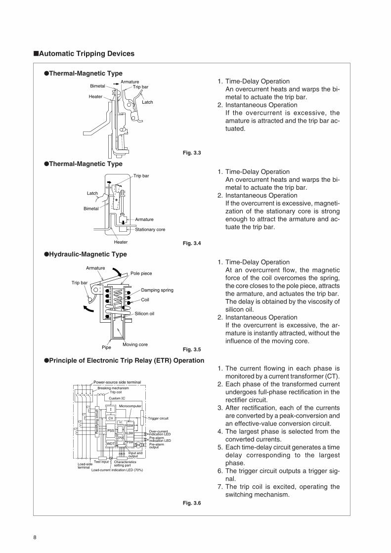
3.3 Automatic Tripping DeviceThere are three types of device, the thermal-magnetictype, the hydraulic-magnetic type and the electronictrip relay type.
Spring tension line
Toggle linkCradle BracketSpring
a) On
b) Off
c) Tripped
ON to OFF dead-point line
OFF to ON dead-point line
Handle centered; indicatestripped condition
8
Automatic Tripping Devices
Thermal-Magnetic Type1. Time-Delay Operation
An overcurrent heats and warps the bi-metal to actuate the trip bar.
2. Instantaneous OperationIf the overcurrent is excessive, theamature is attracted and the trip bar ac-tuated.
Fig. 3.3
Thermal-Magnetic Type1. Time-Delay Operation
An overcurrent heats and warps the bi-metal to actuate the trip bar.
2. Instantaneous OperationIf the overcurrent is excessive, magneti-zation of the stationary core is strongenough to attract the armature and ac-tuate the trip bar.
Fig. 3.4
Hydraulic-Magnetic Type1. Time-Delay Operation
At an overcurrent flow, the magneticforce of the coil overcomes the spring,the core closes to the pole piece, attractsthe armature, and actuates the trip bar.The delay is obtained by the viscosity ofsilicon oil.
2. Instantaneous OperationIf the overcurrent is excessive, the ar-mature is instantly attracted, without theinfluence of the moving core.
Fig. 3.5
Principle of Electronic Trip Relay (ETR) Operation1. The current flowing in each phase is
monitored by a current transformer (CT).2. Each phase of the transformed current
undergoes full-phase rectification in therectifier circuit.
3. After rectification, each of the currentsare converted by a peak-conversion andan effective-value conversion circuit.
4. The largest phase is selected from theconverted currents.
5. Each time-delay circuit generates a timedelay corresponding to the largestphase.
6. The trigger circuit outputs a trigger sig-nal.
7. The trip coil is excited, operating theswitching mechanism.
Fig. 3.6
Armature
Trip bar
Silicon oil
Moving core
Damping spring
Pipe
Coil
Pole piece
Bimetal
Heater
ArmatureTrip bar
Latch
Bimetal
Latch
Heater
Stationary core
Armature
Trip bar
Power-source side terminal
Load-sideterminal
Breaking mechanism
Rec
tifyi
ng c
ircui
t
Test input
Load-current indication LED (70%)
Trip coil
CV
PSS
WDT
Microcomputer
CPU
Characteristicssetting part
A/Dconvertor SSW
LSW
PSW
Input and output
Trigger circuit
Over-currentindication LEDPre-alarmindication LEDPre-alarmoutput
CT
CT
CT
CT
Custom C

9
Table 3.1 Comparison of Thermal-Magnetic, Hydraulic-Magnetic and Electronic TypesItem
Ambient temperature
Frequency
Mounting attitude
Flexibility of operating characteristics
Flexibility of rated current
Thermal-magnetic type
Operating current is affected by ambient temperature (bimetal responds to absolute temperature not temperature rise).
Negligible effect up to several hundred Hz; above that the instantaneous trip is affec-ted due to increased iron losses.
Negligible effect.
Bimetal must provide adequate deflection force and desired temperature characteris-tic. Operating time range is limited.
Units for small rated currents are physically impractical.
Hydraulic-magnetic type
Affected only to the extent that the damp-ing-oil viscosity is affected.
Trip current increases with frequency, due to increased iron losses.
Mounting attitude changes the effective weight of the magnetic core.
Oil viscosity, cylinder, core and spring de-sign, etc., allow a wide choice of operating times.
Coil winding can easily be designed to suit any ampere rating.
Negligible effect up to 630A;Above that operating current decreases due to increase of a fever.
IF distortion is big, minimum operating cur-rent increases.
Distortedwave
Electronic type
Within the range of 50(60)~100% of rated current, any ampere rating are practical.Also, to lower the value of short-time delay or instantaneous trip can be easily done comparatively.
Operating time can be easily shortened.To lengthen operating time is not.
Negligible effect
Tripping current of some types decrease due to CT or condition of operating circuit with high frequency, and others increase.
Negligible effect
For peak value detection, operating current drops.
Ope
ratin
g tim
e
Current
Ope
ratin
g tim
e
Current
Ope
ratin
g tim
e
Ceiling
HorizontalON
ON OFFOFF
Current
Ope
ratin
g tim
e
Current
Ope
ratin
g tim
e
High frequency
Low frequency
Current
Ope
ratin
g tim
e
High frequency
Low frequency
Current
Ope
ratin
g tim
e
High temperature
Low temperature
Current
Ope
ratin
g tim
e
High temperature
Standard temperature
Low temperature
Current
Ope
ratin
g tim
e
Current
Ope
ratin
g tim
e
Current
Ope
ratin
g tim
e
Current
Above 700A
Ope
ratin
g tim
e
Current
Small current width
Current width
Ope
ratin
g tim
eCurrent
Peak valuedetection
Ope
ratin
g tim
e
Current
Ope
ratin
g tim
e
Current

10
3.4 ContactsA pair of contacts comprises a moving contact and afixed contact. The instants of opening and closingimpose the most severe duty. Contact materials mustbe selected with consideration to three major criteria:1. Minimum contact resistance2. Maximum resistance to wear3. Maximum resistance to welding
Silver or silver-alloy contacts are low in resistance,but wear rather easily. Tungsten, or majority-tungstenalloys are strong against wear due to arcing, but ratherhigh in contact resistance. Where feasible, 60%+ sil-ver alloy (with tungsten carbide) is used for contactsprimarily intended for current carrying, and 60%+ tung-sten alloy (with silver) is used for contacts primarilyintended for arc interruption. Large-capacity MCCBsemploy this arrangement, having multicontact pairs,with the current-carrying and arc-interruption dutiesseparated.
3.5 Arc-Extinguishing DeviceArcing, an inevitable aspect of current interruption,must be extinguished rapidly and effectively, in nor-mal switching as well as protective tripping, to mini-mize deterioration of contacts and adjacent insulat-ing materials. In Mitsubishi MCCBs a simple, reliable,and highly effective “de-ion arc extinguisher,” consist-ing of shaped magnetic plates (grids) spaced apart inan insulating supporting frame, is used (Fig. 3.7). Thearc (ionized-path current) induces a flux in the gridsthat attracts the arc, which tends to “lie down” on thegrids, breaking up into a series of smaller arcs, andalso being cooled by the grid heat conduction. Thearc (being effectively longer) thus requires far morevoltage to sustain it, and (being cooler) tends to loseionization and extinguish. If these two effects do notextinguish the arc, as in a very large fault, the elevatedtemperature of the insulating frame will cause gas-sing-out of the frame material, to de-ionize the arc.Ac arcs are generally faster extinguishing due to thezero-voltage point at each half cycle.
3.6 Molded CaseThe integral molded cases used in Mitsubishi MCCBsare constructed of the polyester resin containing glassfibers, the phenolic resin or glass reinforced nylon.They are designed to be suitably arc-, heat- and gas-resistant, and to provide the necessary insulatingspacings and barriers, as well as the physical strengthrequired for the purpose.
3.7 TerminalsThese are constructed to assure electrical efficiencyand reliability, with minimized possibility of localizedheating. A wide variety of types are available for easeof mounting and connection. Compression-bondedtypes and bar types are most commonly used.
3.8 Trip ButtonThis is a pushbutton for external, mechanical trippingof the MCCB locally, without operating the external-accessory shunt trip or undervoltage trip, etc. It en-ables easy checking of breaker resetting, control-cir-cuit devices associated with alarm contacts, etc., andresetting by external handle.
Supportingframe
Grids
Fig. 3.7 The De-Ion Arc Extinguisher
Grid
ArcAttraction force
Induced flux
Fig. 3.8 The Induced-Flux Effect

11
4.1 Overcurrent-Trip Characteristics (DelayTripping)
Tripping times for overcurrents of 130 and 200% ofrated current are given in Table 4.1, assuming ambi-ent temperatures of 40°C, a typical condition insideof panelboards. The figures reflect all poles tested to-gether for 130% tripping, and 105% non-tripping.Within the range of the long-delay-element (thermalor hydraulic) operation, tripping times are substan-tially linear, in inverse relationship to overcurrent mag-nitude.
The tripping times are established to prevent ex-cessive conductor-temperature rise; although timesmay vary among MCCBs of different makers, the lowerlimit is restricted by the demands of typical loads: tung-sten-lamp inrush, starting motor, mercury-arc lamps,etc. The tripping characteristics of Mitsubishi MCCBsare established to best ensure protection against ab-normal currents, while avoiding nuisance tripping.
4.1.1 Ambient Temperature and Thermal TrippingFig. 4.1 is a typical ambient compensation curve(curves differ according to types and ratings), show-ing that an MCCB rated for 40°C ambient use mustbe derated to 90% if used in a 50°C environment. Inan overcurrent condition, for the specified tripping time,tripping would occur at 180% rated current, not 200%.At 25°C, for the same tripping time, tripping wouldoccur at 216%, not 200%.
4.1.2 Hot-State TrippingThe tripping characteristics described above reflect“cold-state tripping” – i.e., overloads increased fromzero – and the MCCB stabilized at rated ambient. Thisis a practical parameter for most uses, but in intermit-tent operations, such as resistance welding, motorpulsing, etc., the “hot state” tripping characteristic mustbe specified, since over-loads are most likely to oc-cur with the MCCB in a heated state, while a certainload current is already flowing.
Where the MCCB is assumed to be at 50% of rat-ing when the overload occurs, the parameter is calledthe 50% hot-state characteristic; if no percentage isspecified, 100% is assumed. Hot-state ratings of 50%and 75% are common.
4.2 Short-Circuit Trip Characteristics (In-stantaneous Tripping)
For Mitsubishi MCCBs with thermal-magnetic trip unitsthe instantaneous-trip current can be specified inde-pendently of the delay characteristic, and in manycases this parameter is adjustable offering consider-able advantage in coordination with other protectionand control devices. For example, in coordination withmotor starters, it is important to set the MCCB instan-taneous-trip element at a lower value than the fusing(destruction) current of the thermal overload relay
(OLR) of the starter.For selective tripping, it must be remembered that
even though the branch-MCCB tripping time may beshorter than the total tripping time of the main MCCB,in a fault condition the latter may also be tripped be-cause its latching curve overlaps the tripping curve ofthe former. The necessary data for establishing therequired compatibility is provided in the MitsubishiMCCB sales catalogues.
The total clearing time for the “instantaneous” trip-ping feature is shown in Fig. 4.3; actual values differfor each MCCB type.
Table 4.1 Overcurrent Tripping Times
Rated current (A)
30 or less31~6364~100101~250251~400401~630631~800801~10001001~12501251~16001601~20002001~4000
Tripping time (minutes, max.)
200% 8.5 4 8.5 81012141618202224
130%6060
120120120120120120120120120120
120120120
120120120
120120120
6060
120
105%
Non-Tripping time (minutes, max.)
20 25
Ambient temperature (:)
% r
atin
g co
mpe
nsat
ion
30 40
110108
100
50 60
90
80
120
Fig. 4.1 Typical Temperature-Compensation Curve
Cold state
Ope
ratin
g tim
e
Current
Hot state
Fig. 4.2 Hot-State-Tripping Curve
4. CHARACTERISTICS AND PERFORMANCE

12
Totalclearingtime
Latching(relay)time
Electromagnetoparatingtime
Time forcontacts toopen
Arc-extinguishingtime
Mechanicaldelaytime
Arcingtime
Fig. 4.3 Instantaneous Tripping Sequence
4.3 Effects of Mounting AttitudesInstantaneous tripping is negligibly affected by mount-ing attitude, for all types of MCCB. Delay tripping isalso negligibly affected in the thermal types, but inthe hydraulic-magnetic types the core-weight effectbecomes a factor. Fig. 4.4 shows the effect, for verti-cal-surface mounting and for two styles of horizontal-surface mounting.
(vertical plane)100%
93%
ON
ON
ON
ONON
ON
ON
ON
90%110%
93%107%
107%
100%
Fig. 4.5 Effects of Nonvertical-Plane Mounting on CurrentRating
4.4 DC Tripping Characteristics of AC-Rated MCCBsTable 4.2 DC Tripping Characteristics
Trip unit
Thermal magnetic
Hydraulic magnetic
Long delay
No effect below 630A frame. Above this, AC types cannot be used for DC.
DC minimum-trip values are 110~140% of AC values.
Instantaneous
DC inst.-trip current is approx. 130% of AC value.
Tripping curve
AC
DC
Overcurrent
Trip
ping
tim
e
AC
DC
Trip
ping
tim
e
Overcurrent
4.5 Frequency CharacteristicsAt commercial frequencies the characteristics ofMitsubishi MCCBs of below 630A frame size are vir-tually constant at both 50Hz and 60Hz (except for theE Line models, the characteristics of MCCBs of 2000Aframe and above vary due to the CT used with thedelay element).
At high frequencies (e.g., 400Hz), both the currentcapacity and delay tripping curves will be reduced byskin effect and increased iron losses.
Performance reduction will differ for different types;at 400Hz it will become 80% of the rating in breakersof maximum rated current for the frame size, and 90%
of the rating in breakers of half of the maximum ratingfor the frame size.
The instantaneous trip current will gradually in-crease with frequency, due to reverse excitation byeddy currents. The rise rate is not consistent, butaround 400Hz it becomes about twice the value at60Hz. Mitsubishi makes available MCCBs especiallydesigned for 400Hz use. Apart from operating char-acteristics they are identical to standard MCCBs (SLine).
Floor-mounted
Overcurrent
Trip
ping
tim
e
Ceiling-mounted
Wall-mounted(horiz. or vert. attitude)
Fig. 4.4 Effect of Mounting Attitude on the Hydraulic-Magnetic MCCB Tripping Curves

13
Line Type Impulse-voltage (kA)
MB
NF
S
C
U
MB30-SW MB50-CW MB50-SWMB100-SW MB225-SW
NF30-CS
NF125-CW NF400-CW NF630-CW NF800-CEWNF63-CW NF250-CW
NF125-RGW NF125-UGW NF250-RGW NF250-UGW
NF125-SW NF125-SGW NF125-HW NF125-HGWNF160-SGW NF160-HGW NF250-SGW NF250-HGWNF400-SW NF400-SEW NF400-HEW NF400-REW NF630-SW NF630-SEW NF630-HEW NF630-REW NF800-SEW NF800-HEW NF800-REW NF1000-SEW NF1250-SEW NF1600-SEW
MB30-CS 4
6
6
8
6
8
4
8
8
NF32-SW NF63-SW NF63-HWNF160-SW NF160-HWNF250-SW NF250-HW
NF400-UEW NF800-UEW
4.7 Dielectric StrengthIn addition to the requirements of the various interna-tional standards, Mitsubishi MCCBs also have theimpulse-voltage withstand capabilities given below(Table 4.4). The impulse voltage is defined as sub-
Frame size
125 or less250
400, 630800
1000~20002500, 30003200, 4000
Operations per hour
1201206020201010
Number of operationsWithout current
8500700040002500250015001500
With current150010001000
500500500500
Total10000
800050003000300020002000
Table 4.3 MCCB Switching Endurance (IEC60947-2)
Table 4.4 MCCB Impulse Withstand Voltage (Uimp)
ing rated current.Electrical tripping endurance in MCCBs with shunt
or undervoltage tripping devices is specified as 10%of the mechanical-endurance number of operationsquoted in IEC standards.
Shunt tripping or undervoltage tripping devices areintended as an emergency trip provision and shouldnot be used for normal circuit-interruption purposes.
4.6 Switching CharacteristicsThe MCCB, specifically designed for protective inter-ruption rather than switching, and requiring high-con-tact pressure and efficient arc-extinguishing capabil-ity, is expected to demonstrate inferior capability tothat of a magnetic switch in terms of the number ofoperations per minute and operation life span. Thespecifications given in Table 4.3 are applicable wherethe MCCB is used as a switch for making and break-
stantially square-wave, with a crest length of0.5~1.5µsec and a tail-length of 32~48µsec. The volt-age is applied between line and load terminals (MCCBoff), and between live parts and ground (MCCB on).

14
5. CIRCUIT BREAKER SELECTION5.1 Circuit Breaker Selection Table
Following Table shows various characteristics of each breaker to consider selection and coordination withupstream devices or loads.
Characteristics
Standard : Standard characteristics MCCBs
Low-inst : Low-inst. MCCBs for Discrimination
When a power fuse (PF) is used as a high-voltage protector, it must be coordinatedwith an MCCBs on the secondary side.
Generator : Generator-Protection MCCBs
These MCCBs have long-time-delay operation shorter than standard type and lowinstantaneous operation.
Mag-Only : Magnetic trip only MCCBs
These are standard MCCBs minus the thermal tripping device. They have no time-delay tripping characteristic, providing protection only against large-magnitude short-circuit faults.
PF short-time tolerancscapacity
Pf.
Tr.
MCCB1
MCCB2
Tim
e
MCCBoperatingcharacteristiccurve
Low-inst.MCCBs
Current

15
690V
525V
500V
440V
415V
400V
380V
230V
AC Breaking
capacity (kA rms)
IEC 60947-2
Icu/Ics
CIRCUIT BREAKER SELECTION TABLEFrame (A)
Type
Rated current In (A)
Rated insulation voltage Ui (V) AC
3, 5, 10, 15, 20, 30
500
–
–
–
–
1.5/1.5
–
1.5/1.5
2.5/2 (240V)
NF30-CS3, 4, 6, 10, 16, 20, 25, 32
600
–
–
2.5/1
2.5/1
2.5/1
5/2
5/2
7.5/4
30
NF32-SW
Number of poles 2 3Standard
Automatic tripping
device
Hydraulic-magnetic
Fixed ampere rating and
fixed instantaneous
2 3
Hydraulic-magnetic
Fixed ampere rating and
fixed instantaneous
3 39 ± 17
5 66 ± 28
10 132 ± 57
15 198 ± 86
20 265 ± 115
30 397 ± 172
Rating (A) and
Inst. (A)
3 33 ± 12
4 44 ± 16
6 66 ± 24
10 110 ± 39
16 176 ± 62
20 220 ± 77
25 275 ± 97
32 352 ± 124
Number of poles –Low-inst
Automatic tripping
device –
–
Rating (A) and
Inst. (A)
–
–
–
Number of poles –Generator
Automatic tripping
device –
–
Rating (A) and
Inst. (A)
–
–
–
Number of poles –Mag-Only
Automatic tripping
device –
–
Rating (A) and
Inst. (A)
2 3
Magnetic
Fixed ampere rating
fixed instantaneous
3 30 ± 6
4 40 ± 8
6 60 ± 12
10 100 ± 20
16 160 ± 32
20 200 ± 40
25 250 ± 50
32 320 ± 64
32

16
690V
525V
500V
440V
415V
400V
380V
230V
AC Breaking
capacity (kA rms)
IEC 60947-2
Icu/Ics
Frame (A)
Type
Rated current In (A)
Rated insulation voltage Ui (V) AC
3, 4, 6, 10, 16, 20, 25, 32, 40, 50, 63
600
–
–
2.5/1
2.5/1
2.5/1
5/2
5/2
7.5/4
NF63-CW
63
Number of poles 2 3Standard
Automatic tripping
device
Hydraulic-magnetic
Fixed ampere rating and
fixed instantaneous
3 33 ± 12 4 44 ± 16 6 66 ± 2410 110 ± 3916 176 ± 6220 220 ± 7725 275 ± 9732 352 ± 12440 440 ± 15450 550 ± 19363 693 ± 224
Rating (A) and
Inst. (A)
Number of poles –Low-inst
Automatic tripping
device –
–
Rating (A) and
Inst. (A)
Number of poles –Generator
Automatic tripping
device –
–
Rating (A) and
Inst. (A)
Number of poles 2 3Mag-Only
Automatic tripping
device
Magnetic
Fixed ampere rating and
fixed instantaneous
Rating (A) and
Inst. (A)
3 30 ± 6 4 40 ± 8 6 60 ± 1210 100 ± 2016 160 ± 3220 200 ± 4025 250 ± 5032 320 ± 6440 400 ± 8050 500 ± 10063 630 ± 126
3, 4, 6, 10, 16, 20, 25, 32, 40, 50, 63
600
–
–
7.5/4
7.5/4
7.5/4
7.5/4
7.5/4
15/8
NF63-SW
2 3 4
Hydraulic-magnetic
Fixed ampere rating and
fixed instantaneous
3 33 ± 12 4 44 ± 16 6 66 ± 2410 110 ± 3916 176 ± 6220 220 ± 7725 275 ± 9732 352 ± 12440 440 ± 15450 550 ± 19363 693 ± 224
–
–
–
–
–
–
2 3 4
Magnetic
Fixed ampere rating and
fixed instantaneous
3 30 ± 6 4 40 ± 8 6 60 ± 1210 100 ± 2016 160 ± 3220 200 ± 4025 250 ± 5032 320 ± 6440 400 ± 8050 500 ± 10063 630 ± 126
10, 16, 20, 25, 32, 40, 50, 63
690
2.5/1
–
7.5/4
10/5
10/5
10/5
10/5
25/13
NF63-HW
2 3 4
Hydraulic-magnetic
Fixed ampere rating and
fixed instantaneous
10 110 ± 3916 176 ± 6220 220 ± 7725 275 ± 9732 352 ± 12440 440 ± 15450 550 ± 19363 693 ± 224
–
–
–
–
–
–
2 3 4
Magnetic
Fixed ampere rating and
fixed instantaneous
10 100 ± 2016 160 ± 3220 200 ± 4025 250 ± 5032 320 ± 6440 400 ± 8050 500 ± 10063 630 ± 126

17
690V
525V
500V
440V
415V
400V
380V
230V
AC Breaking
capacity (kA rms)
IEC 60947-2
Icu/Ics
Frame (A)
Type
Rated current In (A)
Rated insulation voltage Ui (V) AC
50, 63, 80, 100, 125
600
–
–
7.5/4
10/5
10/5
10/5
10/5
30/15
NF125-CW
125
Number of poles 2 3Standard
Automatic tripping
device
Thermal, magnetic
Fixed ampere rating and
fixed instantaneous
50 750 ± 150 63 945 ± 189 80 1200 ± 240100 1500 ± 300125 1500 ± 300
Rating (A) and
Inst. (A)
Number of poles 2 3Low-inst
Automatic tripping
device
Thermal, magnetic
Fixed ampere rating and
fixed instantaneous
Rating (A) and
Inst. (A)
Number of poles –Generator
Automatic tripping
device –
–
Rating (A) and
Inst. (A)
Number of poles 2 3Mag-Only
Automatic tripping
device
Magnetic
Fixed ampere rating and
fixed instantaneous
Rating (A) and
Inst. (A)
50 500 ± 100 63 630 ± 126 80 800 ± 160100 1000 ± 200125 1250 ± 250
16, 20, 32, 40, 50, 63, 80, 100, 125
690
8/4
18/5
18/9
23/13
30/15
30/15
30/15
50/25
NF125-SW
2 3 4
Thermal, magnetic
Fixed ampere rating and
fixed instantaneous
16 600 ± 120 20 600 ± 120 32 600 ± 120 40 600 ± 120 50 750 ± 150 63 945 ± 189 80 1200 ± 240100 1500 ± 300125 1500 ± 300
2 3 4
Thermal, magnetic
Fixed ampere rating and
fixed instantaneous
–
–
–
2 3 4
Magnetic
Fixed ampere rating and
fixed instantaneous
16 160 ± 32 20 200 ± 40 32 320 ± 64 40 400 ± 80 50 500 ± 100 63 630 ± 126 80 800 ± 160100 1000 ± 200125 1250 ± 250
16, 20, 32, 40, 50, 63, 80, 100
690
10/5
22/11
30/15
50/25
50/25
50/25
50/25
100/50
NF125-HW
2 3 4
Thermal, magnetic
Fixed ampere rating and
fixed instantaneous
16 600 ± 120 20 600 ± 120 32 600 ± 120 40 600 ± 120 50 750 ± 150 63 945 ± 189 80 1200 ± 240100 1500 ± 300
–
–
–
–
–
–
2 3 4
Magnetic
Fixed ampere rating and
fixed instantaneous
16 160 ± 32 20 200 ± 40 32 320 ± 64 40 400 ± 80 50 500 ± 100 63 630 ± 126 80 800 ± 160100 1000 ± 200125 1250 ± 250
50 300 ± 60 63 378 ± 76 80 480 ± 96100 600 ± 120125 750 ± 150
16 96 ± 20 20 120 ± 24 32 192 ± 39 40 240 ± 48 50 300 ± 60 63 378 ± 76 80 480 ± 96100 600 ± 120125 750 ± 150

18
690V
525V
500V
440V
415V
400V
380V
230V
AC Breaking
capacity (kA rms)
IEC 60947-2
Icu/Ics
Frame (A)
Type
Rated current In (A)
Rated insulation voltage Ui (V) AC
16-25, 25-40, 40-63, 63-100, 80-125
690
8/8
22/22
30/30
36/36
36/36
36/36
36/36
85/85
NF125-SGW
RT
125
Number of poles 2 3 4Standard
Automatic tripping
device
Thermal, magnetic
• Adjustable ampere rating and
fixed instantaneous (up to 63-100A)
• Adjustable ampere rating and
adjustable instantaneous (80-125A only)
16- 25 250 ± 5025- 40 400 ± 8040- 63 630 ± 12663-100 1000 ± 200
Instantaneous pick up currentVariation is within ±20% of settingcurrent
4 In-10 In
80-125 500-1250
Rating (A) and
Inst. (A)
Number of poles –Low-inst
Automatic tripping
device –
–Rating (A) and
Inst. (A)
Number of poles –Generator
Automatic tripping
device–
–
Rating (A) and
Inst. (A)
Number of poles –Mag-Only
Automatic tripping
device –
Rating (A) and
Inst. (A)
16-32, 32-63, 63-100, 75-125
690
8/8
22/22
30/30
36/36
36/36
36/36
36/36
85/85
NF125-SGW
RE
3 4
Electronic trip relay
Adjustable ampere rating
Adjustable long time delay
operating time, short time delay
pick up, and instantaneous
Instantaneous pick up currentVariation is within ±15% of settingcurrent
16- 32 128- 44832- 63 252-113463-100 400-140075-125 500-1750
–
–
–
3
Electronic trip relay
Adjustable ampere rating
Adjustable long time delay
operating time, short time delay
pick up, and instantaneous
Rating: 16-32A, 32-63A,
63-100A, 75-125A
Inst. : Operating characteristics
must be adjusted as
follows.
STD < 3 (Is setting)
LTD : minimum setting
(TL=12sec setting)
–
MagneticFixed ampere rating andAdjustable instantaneous
–
125
690
8/8
22/22
30/30
36/36
36/36
36/36
36/36
85/85
NF125-SGW
RM
–
–
–
–
–
–
–
–
–
2 3 4
–
Instantaneous pick up currentVariation is within ±20% of settingcurrent
4 In-10 In
125 500-1250
–

19
690V
525V
500V
440V
415V
400V
380V
230V
AC Breaking
capacity (kA rms)
IEC 60947-2
Icu/Ics
Frame (A)
Type
Rated current In (A)
Rated insulation voltage Ui (V) AC
16-25, 25-40, 40-63, 63-100, 80-125
690
20/20
35/35
50/50
65/65
70/70
75/75
75/75
100/100
NF125-HGW
RT
125
Number of poles 2 3 4Standard
Automatic tripping
device
Thermal, magnetic
• Adjustable ampere rating and
fixed instantaneous (up to 80-125A)
• Adjustable ampere rating and
adjustable instantaneous
(80-125A only)
16- 25 250 ± 50
25- 40 400 ± 80
40- 63 630 ± 126
63-100 1000 ± 200
Instantaneous pick up current Variation
is within ±20% of setting current
4 In-10 In
80-125 500-1250
Rating (A) and
Inst. (A)
Number of poles –Low-inst
Automatic tripping
device –
–
Rating (A) and
Inst. (A)
Number of poles –Generator
Automatic tripping
device –
–
Rating (A) and
Inst. (A)
Number of poles –Mag-Only
Automatic tripping
device –
Rating (A) and
Inst. (A)
16-32, 32-63, 63-100, 75-125
690
20/20
35/35
50/50
65/65
70/70
75/75
75/75
100/100
NF125-HGW
RE
3 4
Electronic trip relay
Adjustable ampere rating
Adjustable long time delay
operating time, short time delay
pick up, and instantaneous
Instantaneous pick up current
Variation is within ±15% of setting
current
16- 32 128- 448
32- 63 252-1134
63-100 400-1400
75-125 500-1750
–
–
–
3
Electronic trip relay
Adjustable ampere rating
Adjustable long time delay
operating time, short time delay
pick up, and instantaneous
Rating: 16-32A, 32-63A,
63-100A, 75-125A
Inst. : Operating characteristics
must be adjusted as
follows.
STD < 3 (Is setting)
LTD : minimum setting
(TL=12sec setting)
–
MagneticFixed ampere rating andAdjustable instantaneous
–
125
690
20/20
35/35
50/50
65/65
70/70
75/75
75/75
100/100
NF125-HGW
RM
–
–
–
–
–
–
–
–
–
2 3 4
–
Instantaneous pick up current Variation
is within ±20% of setting current
4 In-10 In
125 500-1250
–
20
690V
525V
500V
440V
415V
400V
380V
230V
AC Breaking
capacity (kA rms)
IEC 60947-2
Icu/Ics
Frame (A)
Type
Rated current In (A)
Rated insulation voltage Ui (V) AC
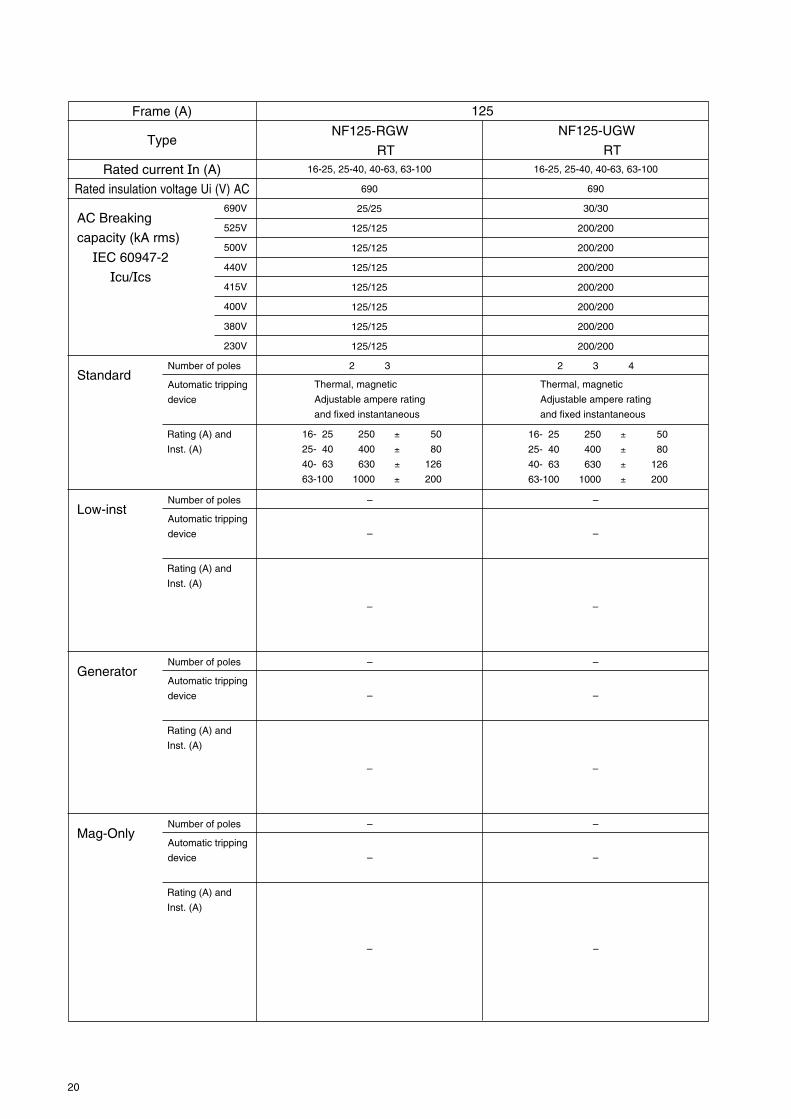
16-25, 25-40, 40-63, 63-100
690
25/25
125/125
125/125
125/125
125/125
125/125
125/125
125/125
NF125-RGW
RT16-25, 25-40, 40-63, 63-100
690
30/30
200/200
200/200
200/200
200/200
200/200
200/200
200/200
125
NF125-UGW
RT
Number of poles 2 3Standard
Automatic tripping
device
Thermal, magnetic
Adjustable ampere rating
and fixed instantaneous
2 3 4
Thermal, magnetic
Adjustable ampere rating
and fixed instantaneous
16- 25 250 ± 50
25- 40 400 ± 80
40- 63 630 ± 126
63-100 1000 ± 200
Rating (A) and
Inst. (A)
16- 25 250 ± 50
25- 40 400 ± 80
40- 63 630 ± 126
63-100 1000 ± 200
Number of poles –Low-inst
Automatic tripping
device –
–
Rating (A) and
Inst. (A)
–
–
–
Number of poles –Generator
Automatic tripping
device –
–
Rating (A) and
Inst. (A)
–
–
–
Number of poles –Mag-Only
Automatic tripping
device –
–
Rating (A) and
Inst. (A)
–
–
–

21
690V
525V
500V
440V
415V
400V
380V
230V
AC Breaking
capacity (kA rms)
IEC 60947-2
Icu/Ics
Frame (A)
Type
Rated current In (A)
Rated insulation voltage Ui (V) AC
125, 150, 160
690
–
–
15/8
25/13
30/15
30/15
30/15
50/25
NF160-SW
160
Number of poles 2 3 4Standard
Automatic tripping
device
Thermal, magnetic
Fixed ampere rating
and fixed instantaneous
125 1750 ± 350
150 2100 ± 420
160 2240 ± 448
Rating (A) and
Inst. (A)
125-160
690
8/8
22/22
30/30
36/36
36/36
36/36
36/36
85/85
NF160-SGW
RT
2 3 4
Thermal, magnetic
Adjustable ampere rating
and adjustable
instantaneous
Instantaneous pick up
current Variation is
within ±20% of setting
current
4 In-10 In
125-160 640-1600
Number of poles –Low-inst
Automatic tripping
device –
–
Rating (A) and
Inst. (A)
Number of poles –Generator
Automatic tripping
device –
–
Rating (A) and
Inst. (A)
Number of poles 2 3 4Mag-Only
Automatic tripping
device
Rating (A) and
Inst. (A)
MagneticFixed ampere rating andfixed instantaneous
125 1250 ± 250
150 1500 ± 300
160 1600 ± 320
–
–
–
–
–
–
–
–
–
80-160
690
8/8
22/22
30/30
36/36
36/36
36/36
36/36
85/85
NF160-SGW
RE
3 4
160
690
8/8
22/22
30/30
36/36
36/36
36/36
36/36
85/85
NF160-SGW
RM
–
–
Instantaneous pick up
current Variation is
within ±15% of setting
current
4 In-14 In
80-160 640-2240
–
–
–
–
–
–
–
MagneticFixed ampere rating andAdjustable instantaneous
–
–
–
–
–
–
2 3 4
–
Electronic trip relay
Adjustable ampere rating
Adjustable long time
delay operating time,
short time delay pick up,
and instantaneous
–
Instantaneous pick up
current Variation is
within ±20% of setting
current
4 In-10 In
160 640-1600
–

22
690V
525V
500V
440V
415V
400V
380V
230V
AC Breaking
capacity (kA rms)
IEC 60947-2
Icu/Ics
Frame (A)
Type
Rated current In (A)
Rated insulation voltage Ui (V) AC
125, 150, 160
690
5/3
–
30/8
50/13
50/13
50/13
50/13
100/25
NF160-HW
160
Number of poles 2 3 4Standard
Automatic tripping
device
Thermal, magnetic
Fixed ampere rating
and fixed instantaneous
125 1750 ± 350
150 2100 ± 420
160 2240 ± 448
Rating (A) and
Inst. (A)
125-160
690
20/20
35/35
50/50
65/65
70/70
75/75
75/75
100/100
NF160-HGW
RT
2 3 4
Thermal, magnetic
Adjustable ampere rating
and adjustable
instantaneous
Instantaneous pick up
current Variation is
within ±20% of setting
current
4 In-10 In
125-160 640-1600
Number of poles –Low-inst
Automatic tripping
device –
–
Rating (A) and
Inst. (A)
Number of poles –Generator
Automatic tripping
device –
–
Rating (A) and
Inst. (A)
Number of poles 2 3 4Mag-Only
Automatic tripping
device
Rating (A) and
Inst. (A)
MagneticFixed ampere rating andfixed instantaneous
125 1250 ± 250
150 1500 ± 300
160 1600 ± 320
–
–
–
–
–
–
–
–
–
80-160
690
20/20
35/35
50/50
65/65
70/70
75/75
75/75
100/100
NF160-HGW
RE
3 4
160
690
20/20
35/35
50/50
65/65
70/70
75/75
75/75
100/100
NF160-HGW
RM
–
–
Instantaneous pick up
current Variation is
within ±15% of setting
current
4 In-14 In
80-160 640-2240
–
–
–
–
–
–
–
MagneticFixed ampere rating andAdjustable instantaneous
–
–
–
–
–
–
–
–
Electronic trip relay
Adjustable ampere rating
Adjustable long time
delay operating time,
short time delay pick up,
and instantaneous
–
Instantaneous pick up
current Variation is
within ±20% of setting
current
4 In-10 In
160 640-1600
–

23
690V
525V
500V
440V
415V
400V
380V
230V
AC Breaking
capacity (kA rms)
IEC 60947-2
Icu/Ics
Frame (A)
Type
Rated current In (A)
Rated insulation voltage Ui (V) AC
125, 150, 175, 200, 225, 250
600
–
–
10/5
15/8
18/9
18/9
18/9
35/18
NF250-CW
250
Number of poles 2 3Standard
Automatic tripping
device
Thermal, magnetic
Fixed ampere rating and
fixed instantaneous
125 1750 ± 350
150 2100 ± 420
175 2450 ± 490
200 2800 ± 560
225 3150 ± 630
250 2500 ± 500
Rating (A) and
Inst. (A)
Number of poles 2 3Low-inst
Automatic tripping
device
Thermal, magnetic
Fixed ampere rating and
fixed instantaneous
Rating (A) and
Inst. (A)
Number of poles –Generator
Automatic tripping
device –
–
Rating (A) and
Inst. (A)
Number of poles 2 3Mag-Only
Automatic tripping
device
Magnetic
Fixed ampere rating and
fixed instantaneous
Rating (A) and
Inst. (A)
125 1250 ± 250
150 1500 ± 300
175 1750 ± 350
200 2000 ± 400
225 2250 ± 450
250 2500 ± 500
125, 150, 175, 200, 225, 250
690
–
–
15/8
25/13
30/15
30/15
30/15
50/25
NF250-SW
2 3 4
Thermal, magnetic
Fixed ampere rating and
fixed instantaneous
125 1750 ± 350
150 2100 ± 420
175 2450 ± 490
200 2800 ± 560
225 3150 ± 630
250 2500 ± 500
2 3 4
Thermal, magnetic
Fixed ampere rating and
fixed instantaneous
–
–
–
2 3 4
Magnetic
Fixed ampere rating and
fixed instantaneous
125 1250 ± 250
150 1500 ± 300
175 1750 ± 350
200 2000 ± 400
225 2250 ± 450
250 2500 ± 500
125, 150, 175, 200, 225, 250
690
5/3
–
30/8
50/13
50/13
50/13
50/13
100/25
NF250-HW
2 3 4
Thermal, magnetic
Fixed ampere rating and
fixed instantaneous
125 1750 ± 350
150 2100 ± 420
175 2450 ± 490
200 2800 ± 560
225 3150 ± 630
250 2500 ± 500
–
–
–
–
–
–
2 3 4
Magnetic
Fixed ampere rating and
fixed instantaneous
125 1250 ± 250
150 1500 ± 300
175 1750 ± 350
200 2000 ± 400
225 2250 ± 450
250 2500 ± 500
6 In 4 In
125 750 ± 150 500 ± 100
150 900 ± 180 600 ± 120
175 1050 ± 210 700 ± 140
200 1200 ± 240 800 ± 160
225 1350 ± 270 900 ± 180
250 1500 ± 300 1000 ± 200
6 In 4 In
125 750 ± 150 500 ± 100
150 900 ± 180 600 ± 120
175 1050 ± 210 700 ± 140
200 1200 ± 240 800 ± 160
225 1350 ± 270 900 ± 180
250 1500 ± 300 1000 ± 200

24
690V
525V
500V
440V
415V
400V
380V
230V
AC Breaking
capacity (kA rms)
IEC 60947-2
Icu/Ics
Frame (A)
Type
Rated current In (A)
Rated insulation voltage Ui (V) AC
125-160, 160-250
690
8/8
22/22
30/30
36/36
36/36
36/36
36/36
85/85
NF250-SGW
RT
250
Number of poles 2 3 4Standard
Automatic tripping
device
Thermal, magnetic
Adjustable ampere rating and
adjustable instantaneous
Instantaneous pick up current
Variation is within ±20% of setting
current
4 In-10 In
125-160 640-1600
160-250 1000-2500
Rating (A) and
Inst. (A)
Number of poles –Low-inst
Automatic tripping
device –
–
Rating (A) and
Inst. (A)
Number of poles –Generator
–
Rating (A) and
Inst. (A)
Number of poles –Mag-Only
Automatic tripping
device –
Rating (A) and
Inst. (A)
125-250
690
8/8
22/22
30/30
36/36
36/36
36/36
36/36
85/85
NF250-SGW
RE
3 4
Electronic trip relay
Adjustable ampere rating
Adjustable long time delay
operating time, short time delay
pick up, and instantaneous
Instantaneous pick up current
Variation is within ±15% of setting
current
4 In-14 In
125-250 1000-3500
–
–
–
–
–
MagneticFixed ampere rating andAdjustable instantaneous
–
250
690
8/8
22/22
30/30
36/36
36/36
36/36
36/36
85/85
NF250-SGW
RM
–
–
–
–
–
–
–
–
2 3 4
–
Instantaneous pick up currentVariation is within ±20% of settingcurrent
4 In-10 In
250 1000-2500
–
–
Automatic tripping
device – – –

25
690V
525V
500V
440V
415V
400V
380V
230V
AC Breaking
capacity (kA rms)
IEC 60947-2
Icu/Ics
Frame (A)
Type
Rated current In (A)
Rated insulation voltage Ui (V) AC
125-160, 160-250
690
20/20
35/35
50/50
65/65
70/70
75/75
75/75
100/100
NF250-HGW
RT
250
Number of poles 2 3 4Standard
Automatic tripping
device
Thermal, magnetic
Adjustable ampere rating and
adjustable instantaneous
Instantaneous pick up current
Variation is within ±20% of setting
current
4 In-10 In
125-160 640-1600
160-250 1000-2500
Rating (A) and
Inst. (A)
Number of poles –Low-inst
Automatic tripping
device –
–
Rating (A) and
Inst. (A)
Number of poles –Generator
–
Rating (A) and
Inst. (A)
Number of poles –Mag-Only
Automatic tripping
device –
Rating (A) and
Inst. (A)
125-250
690
20/20
35/35
50/50
65/65
70/70
75/75
75/75
100/100
NF250-HGW
RE
3 4
Electronic trip relay
Adjustable ampere rating
Adjustable long time delay
operating time, short time delay
pick up, and instantaneous
Instantaneous pick up current
Variation is within ±15% of setting
current
4 In-14 In
125-250 1000-3500
–
–
–
–
–
MagneticFixed ampere rating andAdjustable instantaneous
–
250
690
20/20
35/35
50/50
65/65
70/70
75/75
75/75
100/100
NF250-HGW
RM
–
–
–
–
–
–
–
–
2 3 4
–
Instantaneous pick up currentVariation is within ±20% of settingcurrent
4 In-10 In
250 1000-2500
–
–
Automatic tripping
device – – –

26
690V
525V
500V
440V
415V
400V
380V
230V
AC Breaking
capacity (kA rms)
IEC 60947-2
Icu/Ics
Frame (A)
Type
Rated current In (A)
Rated insulation voltage Ui (V) AC
125-160, 160-225
690
25/25
125/125
125/125
125/125
125/125
125/125
125/125
125/125
NF250-RGW
RT125-160, 160-225
690
30/30
–
200/200
200/200
200/200
200/200
200/200
200/200
250
NF250-UGW
RT
Number of poles 2 3Standard
Automatic tripping
device
Thermal, magnetic
Adjustable ampere rating and
adjustable instantaneous
2 3 4
Thermal, magnetic
Adjustable ampere rating and
adjustable instantaneous
Instantaneous pick up current Variation is within
±20% of setting current
4 In-10 In
125-160 640-1600
160-225 900-2250
Rating (A) and
Inst. (A)
Instantaneous pick up current Variation is within
±20% of setting current
4 In-10 In
125-160 640-1600
160-225 900-2250
Number of poles –Low-inst
Automatic tripping
device –
–
Rating (A) and
Inst. (A)
–
–
–
Number of poles –Generator
Automatic tripping
device –
–
Rating (A) and
Inst. (A)
–
–
–
Number of poles –Mag-Only
Automatic tripping
device –
–
Rating (A) and
Inst. (A)
–
–
–

27
690V
500V
440V
400V
230V
AC Breaking
capacity (kA rms)
IEC 60947-2
Icu/Ics
Frame (A)
Type
Rated current In (A)
Rated insulation voltage Ui (V)
250, 300, 350, 400
690
–
15/8
25/13
36/18
50/25
NF400-CW
400A
Number of poles 2 3Standard
Automatic tripping
device
Thermal, magnetic
Fixed ampere rating and
instantaneous
250 2500 ± 500
300 3000 ± 600
350 3500 ± 700
400 4000 ± 800
Rating (A) and
Inst. (A)
250, 300, 350, 400
690
10/10
30/30
42/42
45/45
85/85
NF400-SW
2 3 4
Thermal, magnetic
Fixed ampere rating and
instantaneous
250 3500 ± 700
300 4200 ± 840
350 4900 ± 980
400 5600 ± 1120
200-400 adjustable
690
10/10
30/30
42/42
50/50
85/85
NF400-SEW
3 4
Electronic trip relayAdjustable ampere ratingAdjustable long time delayoperating time, short time delaypick up and instantaneous
Short time delay pick up currentVariation is within ±15% ofsetting current
2 to 10 Ir200 400-500-600-700-800-
1000-1200-1400-1600-2000
225 450-562.5-675-787.5-900-1125-1350-1575-1800-2250
250 500-625-750-875-1000-1250-1500-1750-2000-2500
300 600-750-900-1050-1200-1500-1800-2100-2400-3000
350 700-875-1050-1225-1400-1750-2100-2450-2800-3500
400 800-1000-1200-1400-1600-2000-2400-2800-3200-4000
Instantaneous pick up currentVariation is within ±15% ofsetting current
4 In-16 In1600-6400
Number of poles 2 3Low-inst
Automatic tripping
device
Thermal, magneticFixed ampere rating andinstantaneous
Rating (A) and
Inst. (A)
–
–
–
–
6 In 4 In250 1500 ± 300 1000 ± 200300 1800 ± 360 1200 ± 240350 2100 ± 420 1400 ± 280400 2400 ± 480 1600 ± 320
Number of poles –Generator
Automatic tripping
device
Rating (A) and
Inst. (A)
– –
–––
Number of poles 2 3Mag-Only
(Inst trip only)
2 3 4 –
Automatic tripping
device
MagneticFixed ampere rating andinstantaneous
MagneticFixed ampere rating andinstantaneous
–––
– –
Rating (A) and
Inst. (A)
250 2500 ± 500300 3000 ± 600350 3500 ± 700400 4000 ± 800
250 2500 ± 500300 3000 ± 600350 3500 ± 700400 4000 ± 800
–
–
28
690V
500V
440V
400V
230V
AC Breaking
capacity (kA rms)
IEC 60947-2
Icu/Ics
Frame (A)
Type
Rated current In (A)
Rated insulation voltage Ui (V)
200-400 adjustable
690
35/18
50/50
65/65
70/70
100/100
NF400-HEW
400A
Number of poles 3 4Standard
Automatic tripping
device
Electronic trip relay
Adjustable ampere rating
Adjustable long time delay
operating time, short time delay
pick up and instantaneous
Short time delay pick up currentVariation is within ±15% ofsetting current
2 to 10 Ir200 400-500-600-700-800-
1000-1200-1400-1600-2000
225 450-562.5-675-787.5-900-1125-1350-1575-1800-2250
250 500-625-750-875-1000-1250-1500-1750-2000-2500
300 600-750-900-1050-1200-1500-1800-2100-2400-3000
350 700-875-1050-1225-1400-1750-2100-2450-2800-3500
400 800-1000-1200-1400-1600-2000-2400-2800-3200-4000
Instantaneous pick up currentVariation is within ±15% ofsetting current
4 In-16 In1600-6400
Rating (A) and
Inst. (A)
200-400 adjustable
690
–
70/35
125/63
125/63
150/75
NF400-REW
3
Electronic trip relay
Adjustable ampere rating
Adjustable long time delay
operating time, short time delay
pick up and instantaneous
Short time delay pick up currentVariation is within ±15% ofsetting current
2 to 10 Ir200 400-500-600-700-800-
1000-1200-1400-1600-2000
225 450-562.5-675-787.5-900-1125-1350-1575-1800-2250
250 500-625-750-875-1000-1250-1500-1750-2000-2500
300 600-750-900-1050-1200-1500-1800-2100-2400-3000
350 700-875-1050-1225-1400-1750-2100-2450-2800-3500
400 800-1000-1200-1400-1600-2000-2400-2800-3200-4000
Instantaneous pick up currentVariation is within ±15% ofsetting current
4 In-16 In1600-6400
200-400 adjustable
690
–
170/170
200/200
200/200
200/200
NF400-UEW
3 4
Electronic trip relay
Adjustable ampere rating
Adjustable long time delay
operating time, short time delay
pick up and instantaneous
Short time delay pick up currentVariation is within ±15% ofsetting current
2 to 10 Ir200 400-500-600-700-800-
1000-1200-1400-1600-2000
225 450-562.5-675-787.5-900-1125-1350-1575-1800-2250
250 500-625-750-875-1000-1250-1500-1750-2000-2500
300 600-750-900-1050-1200-1500-1800-2100-2400-3000
350 700-875-1050-1225-1400-1750-2100-2450-2800-3500
400 800-1000-1200-1400-1600-2000-2400-2800-3200-4000
Instantaneous pick up currentVariation is within ±15% ofsetting current
4 In-16 In1600-6400
Number of poles –Low-inst
Automatic tripping
device
Rating (A) and
Inst. (A)
– –
–
Number of poles –Generator
Automatic tripping
device
Rating (A) and
Inst. (A)
– –
–––
–––
– –
––
–
Number of poles –Mag-Only
(Inst trip only)Automatic tripping
device
Rating (A) and
Inst. (A)
– –
–––
–––

29
690V
500V
440V
400V
230V
AC Breaking
capacity (kA rms)
IEC 60947-2
Icu/Ics
Frame (A)
Type
Rated current In (A)
Rated insulation voltage Ui (V)
500, 600, 630
690
–
18/9
36/18
36/18
50/25
NF630-CW
630A
Number of poles 2 3Standard
Automatic tripping
device
Thermal, magnetic
Fixed ampere rating and
instantaneous
500 5000 ± 1000
600 6000 ± 1200
630 6300 ± 1260
Rating (A) and
Inst. (A)
500, 600, 630
690
10/10
30/30
42/42
50/50
85/85
NF630-SW
2 3 4
Thermal, magnetic
Fixed ampere rating and
instantaneous
300-630 adjustable
690
10/10
30/30
42/42
50/50
85/85
NF630-SEW
3 4
Electronic trip relayAdjustable ampere ratingAdjustable long time delayoperating time, short time delaypick up and instantaneous
Short time delay pick up currentVariation is within ±15% ofsetting current
2 to 10 Ir300 600-750-900-1050-
1200-1500-1800-2100-2400-3000
350 700-875-1050-1225-1400-1750-2100-2450-2800-3500
400 800-1000-1200-1400-1600-2000-2400-2800-3200-4000
500 1000-1250-1500-1750-2000-2500-3000-3500-4000-5000
600 1200-1500-1800-2100-2400-3000-3600-4200-4800-6000
630 1260-1575-1890-2205-2520-3150-3780-4410-5040-6300
Instantaneous pick up currentVariation is within ±15% ofsetting current
4 In-15 In2520-9450
Number of poles 2 3Mag-Only
(Inst trip only)
2 3 4 –
Automatic tripping
device
MagneticFixed ampere rating andinstantaneous
Magnetic
Fixed ampere rating and
instantaneous
Rating (A) and
Inst. (A)
500 5000 ± 1000
600 6000 ± 1200
630 6300 ± 1260
500 5000 ± 1000
600 6000 ± 1200
630 6300 ± 1260
–
–
500 7000 ± 1400
600 8400 ± 1680
630 8820 ± 1764
Number of poles –Low-inst
Automatic tripping
device
Rating (A) and
Inst. (A)
– –
–
Number of poles –Generator
Automatic tripping
device
Rating (A) and
Inst. (A)
– –
–––
–––
– –
––
–

30
690V
500V
440V
400V
230V
AC Breaking
capacity (kA rms)
IEC 60947-2
Icu/Ics
Frame (A)
Type
Rated current In (A)
Rated insulation voltage Ui (V)
630A
Number of polesStandard
Automatic tripping
device
Rating (A) and
Inst. (A)
NF630-REW
Number of polesLow-inst
Automatic tripping
device
Rating (A) and
Inst. (A)
Number of polesGenerator
Automatic tripping
device
Rating (A) and
Inst. (A)
Number of polesMag-Only
(Inst trip only)Automatic tripping
device
Rating (A) and
Inst. (A)
300-630 adjustable
690
–
70/35
125/63
125/63
150/75
3
Electronic trip relay
Adjustable ampere rating
Adjustable long time delay operating time, short
time delay pick up and instantaneous
Short time delay pick up current
Variation is within ±15% of setting current
2 to 10 Ir
300 600-750-900-1050-1200-1500-1800-
2100-2400-3000
350 700-875-1050-1225-1400-1750-2100-
2450-2800-3500
400 800-1000-1200-1400-1600-2000-2400-
2800-3200-4000
500 1000-1250-1500-1750-2000-2500-3000-
3500-4000-5000
600 1200-1500-1800-2100-2400-3000-3600-
4200-4800-6000
630 1260-1575-1890-2205-2520-3150-3780-
4410-5040-6300
Instantaneous pick up current
Variation is within ±15% of setting current
4 In-15 In
2520-9450
–
–
–
–
–
–
–
–
–
300-630 adjustable
690
35/18
50/50
65/65
70/70
100/100
NF630-HEW
3 4
Electronic trip relay
Adjustable ampere rating
Adjustable long time delay operating time, short
time delay pick up and instantaneous
Short time delay pick up current
Variation is within ±15% of setting current
2 to 10 Ir
300 600-750-900-1050-1200-1500-1800-
2100-2400-3000
350 700-875-1050-1225-1400-1750-2100-
2450-2800-3500
400 800-1000-1200-1400-1600-2000-2400-
2800-3200-4000
500 1000-1250-1500-1750-2000-2500-3000-
3500-4000-5000
600 1200-1500-1800-2100-2400-3000-3600-
4200-4800-6000
630 1260-1575-1890-2205-2520-3150-3780-
4410-5040-6300
Instantaneous pick up current
Variation is within ±15% of setting current
4 In-15 In
2520-9450
–
–
–
–
–
–
–
–
–
31
690V
500V
440V
400V
230V
AC Breaking
capacity (kA rms)
IEC 60947-2
Icu/Ics
Frame (A)
Type
Rated current In (A)
Rated insulation voltage Ui (V)
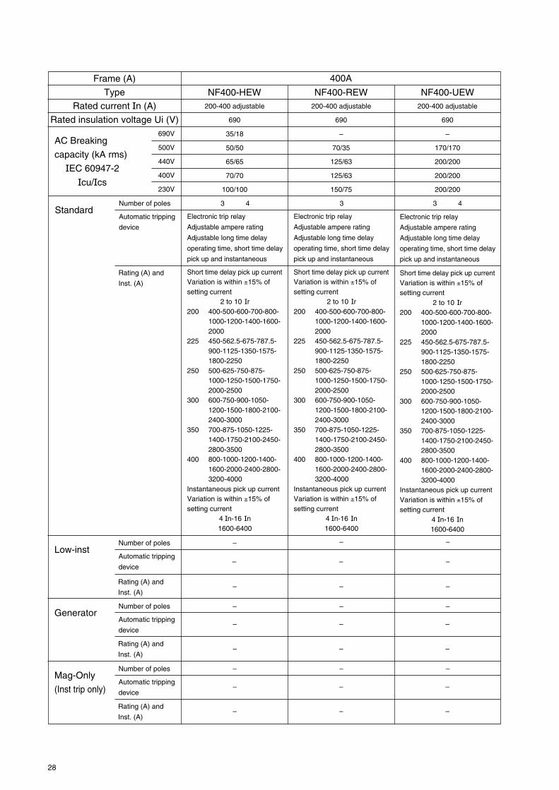
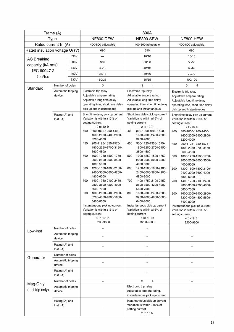
400-800 adjustable
690
—
18/9
36/18
36/18
50/25
NF800-CEW
800A
Number of poles 3Standard
Automatic tripping
device
Electronic trip relay
Adjustable ampere rating
Adjustable long time delay
operating time, short time delay
pick up and instantaneous
Short time delay pick up currentVariation is within ±15% ofsetting current
2 to 10 Ir400 800-1000-1200-1400-
1600-2000-2400-2800-3200-4000
450 900-1125-1350-1575-1800-2250-2700-3150-3600-4500
500 1000-1250-1500-1750-2000-2500-3000-3500-4000-5000
600 1200-1500-1800-2100-2400-3000-3600-4200-4800-6000
700 1400-1750-2100-2450-2800-3500-4200-4900-5600-7000
800 1600-2000-2400-2800-3200-4000-4800-5600-6400-8000
Instantaneous pick up currentVariation is within ±15% ofsetting current
4 In-12 In3200-9600
Rating (A) and
Inst. (A)
400-800 adjustable
690
10/10
30/30
42/42
50/50
85/85
NF800-SEW
3 4
Electronic trip relay
Adjustable ampere rating
Adjustable long time delay
operating time, short time delay
pick up and instantaneous
Short time delay pick up currentVariation is within ±15% ofsetting current
2 to 10 Ir400 800-1000-1200-1400-
1600-2000-2400-2800-3200-4000
450 900-1125-1350-1575-1800-2250-2700-3150-3600-4500
500 1000-1250-1500-1750-2000-2500-3000-3500-4000-5000
600 1200-1500-1800-2100-2400-3000-3600-4200-4800-6000
700 1400-1750-2100-2450-2800-3500-4200-4900-5600-7000
800 1600-2000-2400-2800-3200-4000-4800-5600-6400-8000
Instantaneous pick up currentVariation is within ±15% ofsetting current
4 In-12 In3200-9600
400-800 adjustable
690
15/15
50/50
65/65
70/70
100/100
NF800-HEW
3 4
Electronic trip relay
Adjustable ampere rating
Adjustable long time delay
operating time, short time delay
pick up and instantaneous
Short time delay pick up currentVariation is within ±15% ofsetting current
2 to 10 Ir400 800-1000-1200-1400-
1600-2000-2400-2800-3200-4000
450 900-1125-1350-1575-1800-2250-2700-3150-3600-4500
500 1000-1250-1500-1750-2000-2500-3000-3500-4000-5000
600 1200-1500-1800-2100-2400-3000-3600-4200-4800-6000
700 1400-1750-2100-2450-2800-3500-4200-4900-5600-7000
800 1600-2000-2400-2800-3200-4000-4800-5600-6400-8000
Instantaneous pick up currentVariation is within ±15% ofsetting current
4 In-12 In3200-9600
Number of poles –Low-inst
Automatic tripping
device
Rating (A) and
Inst. (A)
– –
–
Number of poles –Generator
Automatic tripping
device
Rating (A) and
Inst. (A)
– –
–––
–––
– –
––
–
Number of poles –Mag-Only
(Inst trip only)Automatic tripping
device
Rating (A) and
Inst. (A)
3 4 –
––
––
Electronic trip relay
Adjustable ampere rating,
instantaneous pick up current
Instantaneous pick up currentVariation is within ±15% ofsetting current
2 to 10 Ir
32
690V
500V
440V
400V
230V
AC Breaking
capacity (kA rms)
IEC 60947-2
Icu/Ics
Frame (A)
Type
Rated current In (A)
Rated insulation voltage Ui (V)
400-800 adjustable
690
–
70/35
125/63
125/63
150/75
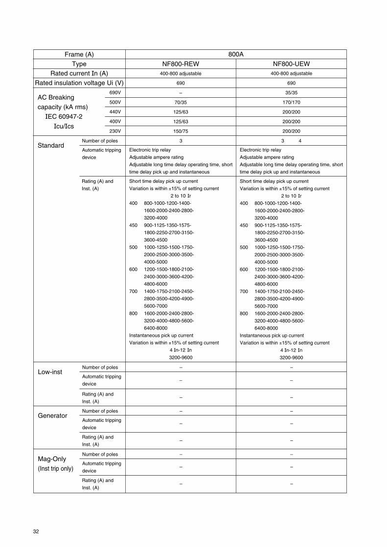
NF800-REW400-800 adjustable
690
35/35
170/170
200/200
200/200
200/200
800A
NF800-UEW
Number of poles 3Standard
Automatic tripping
device
Electronic trip relay
Adjustable ampere rating
Adjustable long time delay operating time, short
time delay pick up and instantaneous
3 4
Electronic trip relay
Adjustable ampere rating
Adjustable long time delay operating time, short
time delay pick up and instantaneous
Short time delay pick up current
Variation is within ±15% of setting current
2 to 10 Ir
400 800-1000-1200-1400-
1600-2000-2400-2800-
3200-4000
450 900-1125-1350-1575-
1800-2250-2700-3150-
3600-4500
500 1000-1250-1500-1750-
2000-2500-3000-3500-
4000-5000
600 1200-1500-1800-2100-
2400-3000-3600-4200-
4800-6000
700 1400-1750-2100-2450-
2800-3500-4200-4900-
5600-7000
800 1600-2000-2400-2800-
3200-4000-4800-5600-
6400-8000
Instantaneous pick up current
Variation is within ±15% of setting current
4 In-12 In
3200-9600
Rating (A) and
Inst. (A)
Short time delay pick up current
Variation is within ±15% of setting current
2 to 10 Ir
400 800-1000-1200-1400-
1600-2000-2400-2800-
3200-4000
450 900-1125-1350-1575-
1800-2250-2700-3150-
3600-4500
500 1000-1250-1500-1750-
2000-2500-3000-3500-
4000-5000
600 1200-1500-1800-2100-
2400-3000-3600-4200-
4800-6000
700 1400-1750-2100-2450-
2800-3500-4200-4900-
5600-7000
800 1600-2000-2400-2800-
3200-4000-4800-5600-
6400-8000
Instantaneous pick up current
Variation is within ±15% of setting current
4 In-12 In
3200-9600
Number of poles –Low-inst
Automatic tripping
device
Rating (A) and
Inst. (A)
Number of poles –Generator
Automatic tripping
device
Rating (A) and
Inst. (A)
–
–
–
–
Number of poles –Mag-Only
(Inst trip only)Automatic tripping
device
Rating (A) and
Inst. (A)
–
–
–
–
–
–
–
–
–
–
–

33
690V
500V
440V
400V
230V
AC Breaking
capacity (kA rms)
IEC 60947-2
Icu/Ics
Frame (A)
Type
Rated current In (A)
Rated insulation voltage Ui (V)
500-1000 adjustable
690
25/13
65/33
85/43
85/43
125/63
NF1000-SEW
1000A
Number of poles 3 4Standard
Automatic tripping
device
Electronic trip relay
Adjustable ampere rating
Adjustable long time delay
operating time, short time delay
pick up and instantaneous
Short time delay pick up currentVariation is within ±15% ofsetting current
2 to 10 Ir500 1000-1250-1500-1750-
2000-2500-3000-3500-4000-5000
600 1200-1500-1800-2100-2400-3000-3600-4200-4800-6000
700 1400-1750-2100-2450-2800-3500-4200-4900-5600-7000
800 1600-2000-2400-2800-3200-4000-4800-5600-6400-8000
900 1800-2250-2700-3150-3600-4500-5400-6300-7200-9000
1000 2000-2500-3000-3500-4000-5000-6000-7000-8000-10000
Instantaneous pick up currentVariation is within ±15% ofsetting current
4 In-12 In4000-12000
Rating (A) and
Inst. (A)
600-1250 adjustable
690
25/13
65/33
85/43
85/43
125/63
NF1250-SEW
3 4
Electronic trip relay
Adjustable ampere rating
Adjustable long time delay
operating time, short time delay
pick up and instantaneous
Short time delay pick up currentVariation is within ±15% ofsetting current
2 to 10 Ir600 1200-1500-1800-2100-
2400-3000-3600-4200-4800-6000
700 1400-1750-2100-2450-2800-3500-4200-4900-5600-7000
800 1600-2000-2400-2800-3200-4000-4800-5600-6400-8000
1000 2000-2500-3000-3500-4000-5000-6000-7000-8000-10000
1200 2400-3000-3600-4200-4800-6000-7200-8400-9600-12000
1250 2500-3125-3750-4375-5000-6250-7500-8750-10000-12500
Instantaneous pick up currentVariation is within ±15% ofsetting current
4 In-12 In5000-15000
800-1600 adjustable
690
25/13
65/33
85/43
85/43
125/63
NF1600-SEW
3 4
Electronic trip relay
Adjustable ampere rating
Adjustable long time delay
operating time, short time delay
pick up and instantaneous
Short time delay pick up currentVariation is within ±15% ofsetting current
2 to 10 Ir800 1600-2000-2400-2800-
3200-4000-4800-5600-6400-8000
1000 2000-2500-3000-3500-4000-5000-6000-7000-8000-10000
1200 2400-3000-3600-4200-4800-6000-7200-8400-9600-12000
1400 2800-3500-4200-4900-5600-7000-8400-9800-11200-14000
1500 3000-3750-4500-5250-6000-7500-9000-10500-12000-15000
1600 3200-4000-4800-5600-6400-8000-9600-11200-12800-16000
Instantaneous pick up currentVariation is within ±15% ofsetting current
4 In-12 In6400-19200
Number of poles –Low-inst
Automatic tripping
device
Rating (A) and
Inst. (A)
– –
–
Number of poles –Generator
Automatic tripping
device
Rating (A) and
Inst. (A)
– –
–––
–––
– –
––
–
Number of polesMag-Only
(Inst trip only)Automatic tripping
device
Rating (A) and
Inst. (A)
1250A 1600A
3 4 3 4 3 4
Electronic trip relay
Adjustable ampere rating,
instantaneous pick up current
Instantaneous pick up currentVariation is within ±15% ofsetting current
2 to 10 Ir
Electronic trip relay
Adjustable ampere rating,
instantaneous pick up current
Electronic trip relay
Adjustable ampere rating,
instantaneous pick up current
Instantaneous pick up currentVariation is within ±15% ofsetting current
2 to 10 Ir
Instantaneous pick up currentVariation is within ±15% ofsetting current
2 to 10 Ir

34
6. PROTECTIVE CO-ORDINATION6.1 General
Type of SystemThe primary purpose of a circuit protection system is to prevent damage to series connected equipment and tominimise the area and duration of power loss. The first consideration is whether an air circuit breaker or moul-ded case circuit breaker is most suitable.The next is the type of system to be used. The three major types are:Fully Rated, Selective and Cascade Back-Up.
Fully RatedThis system is highly reliable, as all of the breakers are rated for the maximum fault level at the point of theirinstallation. Discrimination (selective interruption) can be incorporated in some cases. The disadvantage is thathigh cost branch breakers may be necessary.
Selective-Interruption(Discrimination)Selective Interruption requires that in the event of a fault, only the device directly before the fault will trip, andthat other branch circuits of the same or higher level will not be affected. The range of selective Interruption ofthe main breaker varies considerably depending on the breaker used.
Cascade Back-Up ProtectionThis is an economical approach to the use of circuit breakers, whereby only the main (upstream) breaker hasadequate interrupting capacity for the maximum available fault current. The MCCBs downstream cannot handlethis maximum fault current and rely on the opening of the upstream breaker for protection.
The advantage of the cascade back-up approach is that it facilitates the use of low cost, low fault level breakersdownstream, thereby offering savings in both the cost and size of equipment.
As Mitsubishi MCCBs have a very considerable current limiting effect, they can be used to provide this ‘cas-cade back-up’ protection for downstream circuit breakers.

35
6.2 Interrupting Capacity Consideration
Table 1 230VAC
30·32
63
125
400
630
800
30 or less 50~75 100 150~300
20 or less 30~50 75 100~150 200~500 –
2.5 5 10 15 25 30 35 50 85 100 125 170 200
NF30-CS
NF63-CW
NF125-CW
NF250-CW
NF400-CW
NF630-CW
NF800-CEW
NF160-SWNF250-SW
NF400-SW, NF400-SEW
NF125-SWNF125-SGW
NF160-SGWNF250-SGW
NF32-SW
3ph trans.capacity (kVA)
Interruptingcapacity
(kA)(sym)
1ph trans.capacity (kVA)
NF125-SW
NF1000-SEW~NF1600-SEW
NF800-SEW NF800-UEW
NF400-UEW
2000~3000500~1500
160
250
~
NF630-SW,NF630-SEW
Fra
me
(A)
1000
1600
~
NF125-RGW
C Series S·H Series
NF400-HEW
NF400-REW
NF630-HEW
NF630-REW
NF800-HEW
NF800-REW
7.5
NF63-SW NF63-HW
NF125-HWNF125-HGW
NF125-UGW
NF160-HWNF160-HGWNF250-HWNF250-HGW
NF250-RGW
NF250-UGW
200
30 or less 50~100 150~300 500~1000 1500~2000 2500~5000
400
30·32
63
630
800
2.5 12585655036307.5 10 15 18 25
Table 2 440VAC
125
NF400-CW
NF1000-SEW~NF1600-SEW
NF800-REW
NF250-UGW
NF630-REWNF630-CW
NF800-CEW
NF250-RGW
Trans. capacity(kVA)
Interruptingcapacity
(kA)(sym)
NF63-CW NF63-SW
NF125-CW
NF160-SGWNF250-SGW
NF250-CW
NF125-RGWNF125-SGWNF125-SW
160
250
~
1000
1600
~
NF630-SW,NF630-SEW
Fra
me
(A)
NF125-UGW
1.5
NF32-SWNF30-CS
NF400-SW, NF400-SEW NF400-REW
NF800-UEW
NF400-UEW
42
NF800-SEW
NF400-HEW
NF630-HEW
NF800-HEW
NF160-HWNF250-HW
NF125-HWNF125-HGWNF160-HGWNF250-HGW
NF63-HW
NF160-SWNF250-SW

36
6.3 Selective-Interruption (Discrimination)
6.3.1 Selective-Interruption CombinationFollowing tables show combinations of main-circuitselective coordination breakers and branch breakersand the available selective tripping current at the set-ting points at the branch-circuits.
Short-circuit point
Continuous supply
Healthy circuit
Main breaker
Branch breaker
Selection Conditions1. The main breaker rated current, STD operating time
and INST pickup current are to be set to the maxi-mum values.
2. When selecting the over-current range, also checkthe conformity using the other characteristic curves.
Main breaker
STD pick up current.
Set up STD operating time in the maximum value.
Set up inst pick up current in the maximum value.
Branch breaker
Icu : Rated breaking capacityNote1 : Reted currents of main breakers are maximum values.Note2 : Reted currents of branch breakers are 50A or less.
Main BreakerNote 1
Branch Breaker
BH-D6TYPE C
BH-D6TYPE B
NF125-SGWRE
NF250-SGWRE
Icu(kA) 50 50
6
6
1.6 Note21.6 Note2
1.6 Note2
3.5
3.5
Selective interruption combinations (MCB-MCCB)
230VAC (Sym. kA)

37
Selective interruption combinations (MCCB-MCCB)
440VAC (Sym. kA)
NF12
5-SG
W R
E
NF12
5-HG
W R
E
NF16
0-SG
W R
E
NF16
0-HG
W R
E
NF25
0-SG
W R
E
NF25
0-HG
W R
E
NF4
00-S
EW
NF4
00-H
EW
NF6
30-S
EW
NF6
30-H
EW
NF8
00-C
EW
NF1
000-
SEW
NF1
250-
SEW
NF1
600-
SEW
Main Breaker
Branch Breaker Icu(kA) 36 65 36 65 36 65 42 65 42 65 36
NF8
00-S
EW
42
NF8
00-H
EW
65 85
C
U
NF32-SWMB30-SWNV32-SWNF63-SWMB50-SWNV63-SWNF63-HWNV63-HWNF125-SWMB100-SWNV125-SWNF125-SGW RTNF125-SGW RENF125-HWNV125-HWNF125-HGW RTNF125-HGW RENF160-SWNF160-SGW RTNF160-SGW RENF160-HWNF160-HGW RTNF160-HGW RENF250-SWMB225-SWNV250-SWNV250-SEWNF250-SGW RTNF250-SGW RENF250-HWNV250-HWNV250-HEWNF250-HGW RTNF250-HGW RENF400-SWNV400-SWNF400-SEWNV400-SEWNF400-HEWNV400-HEWNF400-REWNV400-REWNF630-SWNF630-SEWNV630-SWNV630-SEWNF630-HEWNV630-HEWNF630-REWMB50-CWNF63-CWNV63-CWNF125-CWNV125-CWNF250-CWNV250-CWNF400-CWNV400-CWNF630-CWNV630-CWNF125-RGWNV125-RWNF125-UGWNF250-RGWNV250-RWNF250-UGWNF400-UEWNF800-UEW
2.55
7.5
10
25
36
50
6525365065
25
2536365050656542
42
65
125
42
65125
2.5
10
15
25
36
125200125200200200
1.61.6
1.6
1.6
–
–
–
–––––
–
––––––––
–
–
–
–
––
1.6
–
–
–
–
––––––
1.61.6
1.6
1.6
–
–
–
–––––
–
––––––––
–
–
–
–
––
1.6
–
–
–
–
––––––
1.61.6
1.6
1.6
–
–
–
–––––
–
––––––––
–
–
–
–
––
1.6
–
–
–
–
––––––
1.61.6
1.6
1.6
–
–
–
–––––
–
––––––––
–
–
–
–
––
1.6
–
–
–
–
––––––
2.53.5
3.5
3.5
3.5
3.5
3.5
3.5––––
–
––––––––
–
–
–
–
––
2.5
3.5
–
–
–
3.53.5––––
2.53.5
3.5
3.5
3.5
3.5
3.5
3.5––––
–
––––––––
–
–
–
–
––
2.5
3.5
–
–
–
3.53.5––––
2.55
7.5
7.5
5
7.5
7.5
7.56.46.46.46.4
–
6.4–
6.4–
6.4–
6.4–
–
–
–
–
––
2.5
5
–
–
–
1515––––
2.55
7.5
7.5
5
7.5
7.5
7.56.46.46.46.4
–
6.4–
6.4–
6.4–
6.4–
–
–
–
–
––
2.5
5
–
–
–
1515––––
2.55
7.5
10
10
15
18
1510101010
10
10101010101010–
9.5
9.5
9.5
–
––
2.5
10
7.5
–
–
303015159.5–
2.55
7.5
10
10
15
18
1510101010
10
10101010101010–
9.5
9.5
9.5
–
––
2.5
10
7.5
–
–
303015159.5–
2.55
7.5
10
10
15
18
1510101010
10
1010101010101010
10
10
10
–
––
2.5
10
7.5
10
–
3030151515–
2.55
7.5
10
10
15
18
1510101010
10
1010101010101010
10
10
10
–
––
2.5
10
7.5
10
–
4242252515–
2.55
7.5
10
10
15
18
1510101010
10
1010101010101010
10
10
10
–
––
2.5
10
7.5
10
–
5050252515–
2.55
7.5
10
22
36
50
4222252225
22
2225252222252520
20
20
20
20
2020
2.5
10
15
20
20
8585858525–
S·H
Icu : Rated ultimate breaking capacityNote : Rated currents of main breakers are maximum values.

38
Selective interruption combinations (MCCB-MCCB)
230VAC (Sym. kA)
Icu : Rated ultimate breaking capacityNote : Rated currents of main breakers are maximum values.
NF12
5-SG
W R
E
NF12
5-HG
W R
E
NF16
0-SG
W R
E
NF16
0-HG
W R
E
NF25
0-SG
W R
E
NF25
0-HG
W R
E
NF4
00-S
EW
NF4
00-H
EW
NF6
30-S
EW
NF6
30-H
EW
NF8
00-C
EW
NF1
000-
SE
WN
F125
0-S
EW
NF1
600-
SE
W
Main Breaker
Branch Breaker Icu(kA) 85 100 85 100 85 100 85 100 85 100 50
NF8
00-S
EW
85
NF8
00-H
EW
100 125
S·H
C
U
NF32-SWMB30-SWNV32-SWNF63-SWMB50-SWNV63-SWNF63-HWNV63-HWNF125-SWMB100-SWNV125-SWNF125-SGW RTNF125-SGW RENF125-HWNV125-HWNF125-HGW RTNF125-HGW RENF160-SWNF160-SGW RTNF160-SGW RENF160-HWNF160-HGW RTNF160-HGW RENF250-SWMB225-SWNV250-SWNV250-SEWNF250-SGW RTNF250-SGW RENF250-HWNV250-HWNV250-HEWNF250-HGW RTNF250-HGW RENF400-SWNV400-SWNF400-SEWNV400-SEWNF400-HEWNV400-HEWNF400-REWNV400-REWNF630-SWNF630-SEWNV630-SWNV630-SEWNF630-HEWNV630-HEWNF630-REWMB50-CWNF63-CWNV63-CWNF125-CWNV125-CWNF250-CWNV250-CWNF400-CWNV400-CWNF630-CWNV630-CWNF125-RGWNV125-RWNF125-UGWNF250-RGWNV250-RWNF250-UGWNF400-UEWNF800-UEW
7.510
15
25
50
85
100
1005085
100100
50
508585
10010010010085
85
100
150
85
100150
7.5
30
35
50
50
125200125200200200
1.61.6
1.6
1.6
–
–
–
–––––
–
––––––––
–
–
–
–
––
1.6
–
–
–
–
––––––
1.61.6
1.6
1.6
–
–
–
–––––
–
––––––––
–
–
–
–
––
1.6
–
–
–
–
––––––
1.61.6
1.6
1.6
–
–
–
–––––
–
––––––––
–
–
–
–
––
3.5
–
–
–
–
––––––
1.61.6
1.6
1.6
–
–
–
–––––
–
––––––––
–
–
–
–
––
3.5
–
–
–
–
––––––
3.53.5
3.5
3.5
3.5
3.5
3.5
3.5––––
–
––––––––
–
–
–
–
––
5
3.5
–
–
–
3.53.5––––
3.53.5
3.5
3.5
3.5
3.5
3.5
3.5––––
–
––––––––
–
–
–
–
––
5
3.5
–
–
–
3.53.5––––
510
10
10
7.5
7.5
10
7.56.46.46.46.4
–
6.4–
6.4–
6.4–
6.4–
–
–
–
–
––
5
7.5
–
–
–
2222––––
510
10
10
7.5
7.5
10
7.56.46.46.46.4
–
6.4–
6.4–
6.4–
6.4–
–
–
–
–
––
5
7.5
–
–
–
2222––––
7.510
15
20
15
15
25
1510101010
10
10101010101010–
9.5
9.5
9.5
–
––
7.5
10
7.5
–
–
6565––––
7.510
15
20
15
15
25
1510101010
10
10101010101010–
9.5
9.5
9.5
–
––
7.5
10
7.5
–
–
6565––––
7.510
15
20
15
15
25
1510101010
10
1010101010101010
10
10
10
–
––
7.5
10
7.5
10
–
5050181815–
7.510
15
20
15
15
25
1510101010
10
1010101010101010
10
10
10
–
––
7.5
10
7.5
10
–
8585505015–
7.510
15
20
15
15
25
1510101010
10
1010101010101010
10
10
10
–
––
7.5
15
7.5
10
–
8585505015–
7.510
15
25
50
85
100
8550505050
50
5050505050505020
20
20
20
20
2020
7.5
25
25
20
20
12512512512525–

39
Selective interruption combinations (ACB-MCCB)
440VAC (Sym. kA)
NF32-SWMB30-SWMB50-CWNV32-SWNF63-SWNV63-SWMB50-SWNF63-HWNV63-HWNF125-SWNV125-SWMB100-SWNF125-SGW RTNF125-SGW RENF125-HWNV125-HWNF125-HGW RTNF125-HGW RENF160-SWNF160-SGW RTNF160-SGW RENF160-HWNF160-HGW RTNF160-HGW RENF250-SWNV250-SWNV250-SEWMB225-SWNF250-SGW RTNF250-SGW RENF250-HWNV250-HWNV250-HEWNF250-HGW RTNF250-HGW RENF400-SWNV400-SWNF400-SEWNV400-SEWNF400-HEWNV400-HEWNF400-REWNV400-REWNF630-SWNV630-SWNF630-SEWNV630-SEWNF630-HEWNV630-HEWNF630-REWNF800-SEWNV800-SEWNF800-HEWNV800-HEWNF800-REWNF63-CWNV63-CWNF125-CWNV125-CWNF250-CWNV250-CWNF400-CWNV400-CWNF630-CWNV630-CWNF800-CEWNF125-RGWNV125-RWNF125-UGWNF250-RGWNV250-RWNF250-UGWNF400-UEWNF800-UEW
2.5
5
7.5
10
25
36
50
65
25
36
50
65
25
36
50
65
45
50
70
125
50
50
70
125
50
70
125
2.5
10
15
36
36
36
125
200
125
200200200
AE630-SW
65
AE1000-SW
65
AE1250-SW
65
AE1600-SW
65
AE2000-SWA
65
AE2000-SW
85
AE2500-SW
85
AE3200-SW
85
AE4000-SWA
85
2.5
5
7.5
9(10)
7(30)
9(36)
9(50)
9(65)
7(25)
9(36)
9(50)
9(65)
7(30)
7(36)
7(50)
7(65)
–
9(50)
9(65)
9(65)
–
–
–
–
–
–
–
2.5
9(10)
9(18)
–
–
–
35(65)
50(65)
9(65)
9(65)9(65)
–
2.5
5
7.5
10
20(30)
20(36)
30(50)
20(65)
14(25)
15(36)
15(50)
15(65)
14(30)
15(36)
15(50)
15(65)
–
15(50)
15(65)
15(65)
–
15(50)
15(65)
15(65)
–
–
–
2.5
10
15(18)
15(36)
–
–
65
65
50(65)
6515(65)
–
2.5
5
7.5
10
25(30)
36
50
36(65)
19(25)
25(36)
25(50)
25(65)
19(30)
25(36)
25(50)
25(65)
18(45)
18(50)
18(65)
18(65)
–
18(50)
18(65)
18(65)
18(50)
18(65)
18(65)
2.5
10
18
18(36)
–
18(36)
65
65
65
6518(65)18(65)
2.5
5
7.5
10
30
36
50
65
25
36
42(50)
42(65)
25(30)
36
42(50)
42(65)
24(45)
24(50)
24(65)
24(65)
24(50)
24(50)
24(65)
24(65)
24(50)
24(65)
24(65)
2.5
10
18
24(36)
24(36)
24(36)
65
65
65
6529(65)24(65)
2.5
5
7.5
10
30
36
50
65
25
36
50
65
30
36
50
65
33(45)
30(50)
30(70)
30(75)
30(50)
30(50)
30(70)
30(75)
30(50)
30(70)
30(75)
2.5
10
18
25(36)
30(36)
30(36)
85
85
85
8548(75)30(75)
2.5
5
7.5
10
30
36
50
65
25
36
42(50)
42(65)
25(30)
36
42(50)
42(65)
24(45)
24(50)
24(65)
24(65)
24(50)
24(50)
24(65)
24(65)
24(50)
24(65)
24(65)
2.5
10
18
24(36)
24(36)
24(36)
65
65
65
6529(65)24(65)
2.5
5
7.5
10
30
36
50
65
25
36
50
65
30
36
50
65
45(45)
39(50)
39(70)
39(75)
37(50)
37(50)
37(70)
37(75)
37(50)
37(70)
37(75)
2.5
10
18
36
36
36
85
85
85
8585
37(75)
2.5
5
7.5
10
30
36
50
65
25
36
50
65
30
36
50
65
45
50
70
80
50
50
48(70)
48(75)
48(50)
48(70)
48(75)
2.5
10
18
36
36
36
85
85
85
8585
68(75)
2.5
5
7.5
10
30
36
50
65
25
36
50
65
30
36
50
65
45
50
70
80
50
50
48(70)
48(75)
48(50)
48(70)
48(75)
2.5
10
18
36
36
36
85
85
85
8585
68(75)
NF-U
NF-C·
NV-C
NF-S·
NV-S·
MB·
MN
Main Circuit Breaker
Low-Voltage Air Circuit Breaker AE-SWSingle Unit Breaking CapacityBranch Circuit Breaker
Note1 : The values in the table represent the max. rated current for both Series AE-SW air circuit breakers and branch breakers, and theselective co-ordination applies when the AE-SW siries air circuit breakers instantaneous pick up is set to maximum.
Note2 : The numerals shown in parentheses are for AE-SW with MCR. (When set MCR.)
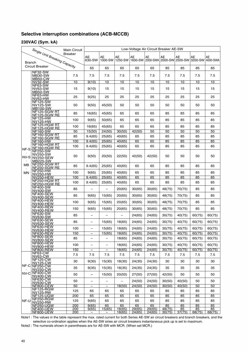
40
Selective interruption combinations (ACB-MCCB)
230VAC (Sym. kA)
Main Circuit Breaker
Low-Voltage Air Circuit Breaker AE-SWSingle Unit Breaking CapacityBranch Circuit Breaker
NF32-SWMB30-SWMB50-CWNV32-SWNF63-SWNV63-SWMB50-SWNF63-HWNV63-HWNF125-SWNV125-SWMB100-SWNF125-SGW RTNF125-SGW RENF125-HWNV125-HWNF125-HGW RTNF125-HGW RENF160-SWNF160-SGW RTNF160-SGW RENF160-HWNF160-HGW RTNF160-HGW RENF250-SWNV250-SWNV250-SEWMB225-SWNF250-SGW RTNF250-SGW RENF250-HWNV250-HWNV250-HEWNF250-HGW RTNF250-HGW RENF400-SWNV400-SWNF400-SEWNV400-SEWNF400-HEWNV400-HEWNF400-REWNV400-REWNF630-SWNV630-SWNF630-SEWNV630-SEWNF630-HEWNV630-HEWNF630-REWNF800-SEWNV800-SEWNF800-HEWNV800-HEWNF800-REWNF63-CWNV63-CWNF125-CWNV125-CWNF250-CWNV250-CWNF400-CWNV400-CWNF630-CWNV630-CWNF800-CEWNF125-RGWNV125-RWNF125-UGWNF250-RGWNV250-RWNF250-UGWNF400-UEWNF800-UEW
7.5
10
15
25
50
85
100
100
50
85
100
100
50
85
100
100
100
85
85
100
150
85
85
100
150
85
100
150
7.5
30
35
50
50
50
125
200
125
200200200
AE630-SW
65
AE1000-SW
65
AE1250-SW
65
AE1600-SW
65
AE2000-SWA
65
AE2000-SW
85
AE2500-SW
85
AE3200-SW
85
AE4000-SWA
85
7.5
9(10)
9(10)
9(25)
9(50)
16(65)
9(65)
16(65)
15(50)
9.4(65)
9.4(65)
9.4(65)
9(50)
9.4(65)
9(65)
9.4(65)
9.4(65)
–
9(65)
9(65)
9(65)
–
–
–
–
–
–
–
7.5
9(30)
9(35)
–
–
–
65
65
9(65)
9(65)9(65)
–
7.5
10
15
25
45(50)
45(65)
50(65)
45(65)
24(50)
25(65)
25(65)
25(65)
20(50)
25(65)
25(65)
25(65)
25(65)
–
15(65)
15(65)
15(65)
–
15(65)
15(65)
15(65)
–
–
–
7.5
15(30)
15(35)
15(50)
–
–
65
65
65
6515(65)
–
7.5
10
15
25
50
65
65
65
30(50)
40(65)
40(65)
40(65)
22(50)
40(65)
40(65)
40(65)
40(65)
20(65)
20(65)
20(65)
20(65)
–
18(65)
18(65)
18(65)
18(65)
18(65)
18(65)
7.5
18(30)
18(35)
20(50)
–
18(50)
65
65
65
6518(65)18(65)
7.5
10
15
25
50
65
65
65
42(50)
65
65
65
42(50)
65
65
65
65
30(65)
30(65)
30(65)
30(65)
24(65)
24(65)
24(65)
24(65)
24(65)
24(65)
24(65)
7.5
24(30)
24(35)
27(50)
24(50)
24(50)
65
65
65
6529(65)24(65)
7.5
10
15
25
50
65
65
65
50
65
65
65
42(50)
65
65
65
65
30(65)
30(65)
30(65)
30(65)
24(65)
24(65)
24(65)
24(65)
24(65)
24(65)
24(65)
7.5
24(30)
24(35)
27(50)
24(50)
24(50)
65
65
65
6529(65)24(65)
NF-U
NF-C·
NV-C
NF-S·
NV-S·
MB·
MN
7.5
10
15
25
50
85
85
85
50
85
85
85
50
85
85
85
85
48(75)
48(75)
48(75)
48(75)
30(75)
30(75)
30(75)
30(75)
30(75)
30(75)
30(75)
7.5
30
35
42(50)
30(50)
30(50)
85
85
85
8548(75)30(75)
7.5
10
15
25
50
85
85
85
50
85
85
85
50
85
85
85
85
70(75)
70(75)
70(75)
70(75)
40(75)
40(75)
40(75)
40(75)
40(75)
40(75)
40(75)
7.5
30
35
50
40(50)
40(50)
85
85
85
8585
37(75)
7.5
10
15
25
50
85
85
85
50
85
85
85
50
85
85
85
85
85
85
85
85
60(75)
60(75)
60(75)
60(75)
60(75)
60(75)
60(75)
7.5
30
35
50
50
50
85
85
85
8585
68(75)
7.5
10
15
25
50
85
85
85
50
85
85
85
50
85
85
85
85
85
85
85
85
60(75)
60(75)
60(75)
60(75)
60(75)
60(75)
60(75)
7.5
30
35
50
50
50
85
85
85
8585
68(75)
Note1 : The values in the table represent the max. rated current for both Series AE-SW air circuit breakers and branch breakers, and theselective co-ordination applies when the AE-SW siries air circuit breakers instantaneous pick up is set to maximum.
Note2 : The numerals shown in parentheses are for AE-SW with MCR. (When set MCR.)

41
6.4 Cascade Back-up Protection
6.4.1 Cascade Back-up CombinationsFollowing tables show the available MCCB combina-tions for cascade interruption and their interruptingcapacity.
Fault point
Branchbreaker
Branchbreaker
Main breaker
MainCircuitBreaker
S·H
C
25
440VAC (sym. kA)
Interrupting Capacity (kA)
NF12
5-SW
, NV1
25-S
W
36
NF
125-
SG
W
50
NF12
5-HW
, NV1
25-H
W
65
NF
125-
HG
W
25
NF
160-
SW
36
NF
160-
SG
W
50
NF
160-
HW
65
NF
160-
HG
W
25
NF25
0-SW
, NV2
50-S
W
36
NF
250-
SG
W
50
NF25
0-HW
, NV2
50-H
W
65
NF
250-
HG
W
42
NF40
0-SW
, NV4
00-S
W
65
NF40
0-HEW
, NV4
00-H
EW
125
NF40
0-REW
, NV4
00-R
EW
42
NF63
0-SW
, NV6
30-S
W
65
NF63
0-HEW
, NV6
30-H
EW
125N
F63
0-R
EW
42NF
800-
SEW
, NV8
00-S
EW65
NF80
0-HEW
, NV8
00-H
EW
125
NF
800-
RE
W
85
NF1000
-SEW,
NF1250
-SEW,
NF1600
-SEW
15
NF25
0-CW
, NV2
50-C
W
25
NF40
0-CW
, NV4
00-C
W
36
NF63
0-CW
, NV6
30-C
W
36
NF
800-
CE
W
125
NF12
5-RG
W, N
V125
-RW
200
NF
125-
UG
W
125
NF25
0-RG
W, N
V250
-RW
200
NF
250-
UG
W
200
NF
400-
UE
W
200
NF
800-
UE
W
S · H C U
NF32-SWMB30-SWNV32-SWNF63-SWMB50-SWNV63-SWNF63-HWNV63-HWNF125-SWMB100-SWNV125-SWNF125-SGWNF125-HWNV125-HWNF125-HGWNF160-SWNF160-SGWNF160-HWNF160-HGWNF250-SWMB225-SWNV250-SWNV250-SEWNF250-SGWNF250-HWNV250-HWNV250-HEWNF250-HGWNF400-SWNF400-SEWNV400-SWNV400-SEWNF630-SWNF630-SEWNV630-SWNV630-SEWMB50-CWNF63-CWNV63-CWNF125-CWNV125-CWNF250-CWNV250-CWNF400-CWNV400-CWNF630-CWNV630-CW
2.5
5
7.5
7.5
10
25
36
50
6525365065
25
36
50
65
42
42
2.5
10
15
25
36
10
14
14
14
20
–
–
–
–––––
–
–
–
–
–
–
10
20
–
–
–
14
14
20
20
30
36
–
–
–––––
–
–
–
–
–
–
14
30
–
–
–
14
14
20
20
30
50
50
–
–––––
–
–
–
–
–
–
14
30
–
–
–
14
14
20
20
30
50
50
65
–––––
–
–
–
–
–
–
14
30
–
–
–
5
10
15
10
18
–
–
–
–––––
–
–
–
–
–
–
5
14
–
–
–
5
10
15
10
18
36
–
–
–––––
–
–
–
–
–
–
5
14
–
–
–
5
10
10
10
–
42
42
–
–––––
–
–
–
–
–
–
5
14
–
–
–
5
10
15
10
18
50
50
65
–––
65–
–
–
–
–
–
–
5
14
–
–
–
5
10
15
10
18
–
–
–
–––––
–
–
–
–
–
–
5
14
25
–
–
5
10
15
10
18
36
–
–
–––––
–
–
–
–
–
–
5
14
25
–
–
5
10
10
10
–
42
42
–
–––––
–
–
–
–
–
–
5
14
25
–
–
5
10
15
10
18
50
50
65
–––65–
–
–
65
–
–
–
5
14
25
–
–
–
7.5
15
–
15
35
–
–
–35–––
35
–
–
–
–
–
–
14
30
35
–
–
7.5
10
–
15
35
–
65
–505065–
50
50
65
–
65
–
–
14
30
35
–
–
7.5
10
–
15
35
–
65
–505065–
50
50
65
–
65
–
–
14
30
35
–
–
7.5
10
–
14
35
–
–
–35–––
35
–
–
–
–
–
–
14
25
35
42
–
7.5
10
–
14
35
–
65
–505065–
50
50
65
–
65
65
–
14
25
35
50
–
7.5
10
–
14
35
–
65
–505065–
50
50
65
–
65
65
–
14
25
35
50
–
–
10
–
–
30
–
–
–35–––
35
–
–
–
–
–
–
14
20
35
42
–
–
10
–
–
35
–
65
–505065–
50
50
65
–
65
65
–
14
20
35
50
–
–
10
–
–
35
–
65
–505065–
50
50
65
–
65
65
–
14
20
35
50
–
–
–
–
–
30
–
–
–505065–
–
–
–
–
–
–
–
–
–
30
42
5
–
–
–
–
–
–
–
–––––
–
–
–
–
–
–
5
–
–
–
–
–
–
10
10
–
–
–
–
–––––
–
–
–
–
–
–
–
14
18
–
–
–
–
10
10
–
–
–
–
–––––
–
–
–
–
–
–
–
14
18
–
–
–
–
–
–
–
–
–
–
–––––
–
–
–
–
–
–
–
14
18
–
–
35
50
50
50
125
125
125
125
125––––
–
–
–
–
–
–
35
125
–
–
–
125
125
125
125
125
200
200
200
200––––
–
–
–
–
–
–
125
200
–
–
–
35
35
50
50
50
125
125
125
125125125125125
125
125
125
125
–
–
35
50
125
–
–
50
50
50
50
50
200
200
200
200200200200200
200
200
200
200
–
–
50
125
200
–
–
–
–
10
–
–
50
50
200
2008585200200
85
85
200
200
200
–
5
14
50
50
–
–
–
10
–
–
35
–
85
858585200200
85
85
200
200
200
200
–
14
25
50
200
BranchCircuitBreaker

42
S·H
C
BH
50
230VAC (sym. kA)
Interrupting Capacity (kA)
NF12
5-SW
, NV1
25-S
W
85
NF
125-
SG
W
100
NF12
5-HW
, NV1
25-H
W
100
NF
125-
HG
W
50
NF
160-
SW
85
NF
160-
SG
W
100N
F16
0-H
W100
NF
160-
HG
W50
NF25
0-SW
, NV2
50-S
W
85
NF
250-
SG
W
100
NF25
0-HW
, NV2
50-H
W
100
NF
250-
HG
W
85
NF40
0-SW
, NV4
00-S
W
100
NF40
0-HEW
, NV4
00-H
EW
150
NF40
0-REW
, NV4
00-R
EW
85
NF63
0-SW
, NV6
30-S
W
100
NF63
0-HEW
, NV6
30-H
EW
150
NF
630-
RE
W
85
NF80
0-SEW
, NV8
00-S
EW
100
NF80
0-HEW
, NV8
00-H
EW
150
NF
800-
RE
W
125
NF1000
-SEW,
NF1250
-SEW,
NF1600
-SEW
35
NF25
0-CW
, NV2
50-C
W
50
NF40
0-CW
, NV4
00-C
W
50
NF63
0-CW
, NV6
30-C
W
50
NF
800-
CE
W
125
NF12
5-RG
W, N
V125
-RW
200
NF
125-
UG
W
125
NF25
0-RG
W, N
V250
-RW
200
NF
250-
UG
W
200
NF
400-
UE
W
200
NF
800-
UE
W
S · H C U
NF32-SWMB30-SWNV32-SWNF63-SWMB50-SWNV63-SWNF63-HWNV63-HWNF125-SWMB100-SWNV125-SWNF125-SGWNF125-HWNV125-HWNF125-HGWNF160-SWNF160-SGWNF160-HWNF160-HGWNF250-SWMB225-SWNV250-SWNV250-SEWNF250-SGWNF250-HWNV250-HWNV250-HEWNF250-HGWNF400-SWNF400-SEWNV400-SWNV400-SEWNF630-SWNF630-SEWNV630-SWNV630-SEWMB50-CWNF63-CWNV63-CWNF125-CWNV125-CWNF250-CWNV250-CWNF400-CWNV400-CWNF630-CWNV630-CWBHBH-P
7.5
10
15
15
25
50
85
100
1005085100100
50
85
100
100
85
85
7.5
30
35
50
50
2.5
42
42
42
42
50
–
–
–
–––––
–
–
–
–
–
–
35
35
–
–
–
30
50
50
85
85
85
85
–
–
–––––
–
–
–
–
–
–
50
85
–
–
–
42
50
50
85
85
100
100
100
–
–––––
–
–
–
–
–
–
50
85
–
–
–
42
50
50
85
85
100
100
100
–
–––––
–
–
–
–
–
–
50
85
–
–
–
42
10
35
35
35
50
–
–
–
–––––
–
–
–
–
–
–
10
50
–
–
–
5
10
35
35
35
50
85
–
–
–85–––
–
–
–
–
–
–
10
50
–
–
–
7.5
10
35
35
35
50
85
–
–
–85–––
–
–
–
–
–
–
10
50
–
–
–
7.5
10
35
35
35
50
85
–
–
–85–––
–
–
–
–
–
–
10
50
–
–
–
7.5
10
35
35
35
50
–
–
–
–––––
–
–
–
–
–
–
10
50
50
–
–
5
10
35
35
35
50
85
–
–
–85–––
85
–
–
–
–
–
10
50
50
–
–
7.5
10
35
35
35
50
85
–
–
–85–––
85
–
–
–
–
–
10
50
50
–
–
7.5
10
35
35
35
50
85
–
–
–85–––
85
–
–
–
–
–
10
50
50
–
–
7.5
–
14
30
–
50
85
–
–
–85–––
85
–
–
–
–
–
–
50
50
85
–
–
–
14
30
–
50
85
–
–
–85–––
85
–
–
–
–
–
–
50
50
85
–
–
–
14
30
–
50
85
–
–
–85–––
85
–
–
–
–
–
–
50
50
85
–
–
–
14
30
–
50
85
–
–
–85–––
85
–
–
–
–
–
–
50
50
85
85
–
–
14
30
–
50
85
–
–
–85–––
85
–
–
–
–
–
–
50
50
85
85
–
–
14
30
–
50
85
–
–
–85–––
85
–
–
–
–
–
–
50
50
85
85
–
–
–
–
–
–
–
–
–
–70–––
70
–
–
–
–
–
–
–
–
85
85
–
–
–
–
–
–
–
–
–
–70–––
70
–
–
–
–
–
–
–
–
85
85
–
–
–
–
–
–
–
–
–
–70–––
70
–
–
–
–
–
–
–
–
85
85
–
–
–
–
–
–
–
–
–
–70–––
70
–
–
–
100
100
–
–
–
85
85
–
7.5
25
25
25
–
–
–
–
–––––
–
–
–
–
–
–
–
–
–
–
–
5
–
14
–
–
30
–
–
–
–––––
–
–
–
–
–
–
–
–
–
–
–
–
–
14
–
–
30
–
–
–
–––––
–
–
–
–
–
–
–
–
–
–
–
–
–
–
–
–
–
–
–
–
–––––
–
–
–
–
–
–
–
–
–
–
–
–
125
125
125
125
125
125
125
125
125––––
–
–
–
–
–
–
125
125
–
–
–
125
200
200
200
200
200
200
200
200
200––––
–
–
–
–
–
–
200
200
–
–
–
200
35
35
85
85
85
125
125
125
125125125125125
125
125
125
125
–
–
35
85
125
–
–
–
50
50
125
125
125
200
200
200
200200200200200
200
200
200
200
–
–
50
125
200
–
–
–
–
–
–
–
–
200
200
200
200200200200200
200
200
200
200
200
–
–
50
200
200
–
–
–
–
–
–
–
125
125
125
125125125200200
125
125
200
200
200
200
–
–
50
200
200
–
MainCircuitBreaker
BranchCircuitBreaker
Cascade Back-up Combinations
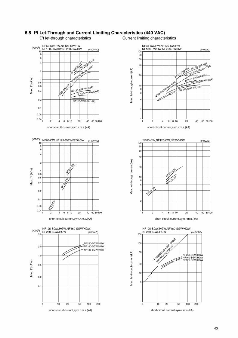
43
6.5 I2t Let-Through and Current Limiting Characteristics (440 VAC)I2t let-through characteristics Current limiting characteristics
NF63-SW/HW,NF125-SW/HWNF160-SW/HW,NF250-SW/HW
NF63-CW,NF125-CW,NF250-CW
NF125-SGW/HGW,NF160-SGW/HGW,NF250-SGW/HGW
NF63-CW,NF125-CW,NF250-CW
NF63-SW/HW,NF125-SW/HWNF160-SW/HW,NF250-SW/HW
Max
. I2 t
(A
2 -s)
(106)
short-circuit current,sym.r.m.s.(kA)
1 2 64 4020108 60 80100
(440VAC)
(440VAC)
(440VAC) (440VAC)
(440VAC)
(440VAC)
NF125-SGW/HGW,NF160-SGW/HGW,NF250-SGW/HGW
6
108
4
2
1
0.6
0.8
0.4
0.2
0.1
0.06
0.04
Max
. I2 t
(A
2 -s)
(106)
short-circuit current,sym.r.m.s.(kA)
1 2 64 4020108 60 80100
6
10
(106)5.0
8
4
2
Max
. I2 t
(A
2 -s)
short-circuit current,sym.r.m.s.(kA)
103 20 50 100 200
2.0
1.0
0.5
0.2
0.1
1
0.6
0.8
0.4
0.2
0.1
0.06
0.04
short-circuit current,sym.r.m.s.(kA)
1 2 64 4020108 60 80100
60
100
80
40
20
108
6
4
2
1
NF160
/250
-SW
NF160/250-HWNF6
3-SW
/HW
NF125-SW/H
W(40~125A)
NF125-SW/HW(32A)
NF125-SW/HW(20A)
NF160/250-SW NF160/250-HW
NF125-SW/HW(40~125A)
NF63-SW/H
W(32~63A)
NF63-SW/HW(16A)
NF125-SW/HW(32A)
NF125-SW/HW(20A)
NF125-SW/HW(16A)
NF125-SW/HW(16A)
Max
. Iet
-thr
ough
cur
rent
(kA
)
short-circuit current,sym.r.m.s.(kA)
1 2 64 4020108 60 80100
6
10
20
40
60
80
100
8
4
2
1
Max
. Iet
-thr
ough
cur
rent
(kA
)
short-circuit current,sym.r.m.s.(kA)
3 10 20 50 100 2001
100
200
50
20
10
5
Max
. Iet
-thr
ough
cur
rent
(kA
)
NF1
25-C
W
NF6
3-C
W
NF250
-CW
NF125-CW
NF63-CW
NF250-CW
NF250-SGW/HGWNF160-SGW/HGWNF125-SGW/HGW
NF250-SGW/HGWNF160-SGW/HGWNF125-SGW/HGWPro
spec
tive
shor
t-circ
uit
curre
nt,a
sym
.pea
k

44
short-circuit current,sym.r.m.s.(kA)
1 2 4 10 20 40 6080100 20086
100
200
400
8060
40
20
1086
4
2
1
Max
. Iet
-thr
ough
cur
rent
(kA
)short-circuit current,sym.r.m.s.(kA)
3 10 20 50 100 2001
200
100
50
20
10
5
Max
. Iet
-thr
ough
cur
rent
(kA
)
Max
. I2 t
(A
2 -s)
(106)
short-circuit current,sym.r.m.s.(kA)
3 10 20 50 100 200
5.0
2.0
1.0
0.5
0.2
0.1
NF400-UEW,NF800-UEW NF400-UEW,NF800-UEW
Max
. I2 t
(A
2 -s)
(106)
short-circuit current,sym.r.m.s.(kA)
1 2 4 10 20 40 60 80100 20086
1086
4
1
2
20
40
0.80.6
0.4
0.2
0.1
NF800-UEW
NF400-UEW
Prosp
ectiv
e sh
ort-c
ircuit
curre
nt,a
sym
.pea
k NF800-UEW
NF400-UEW
Prosp
ectiv
e sh
ort-c
ircuit
curre
nt,a
sym
.pea
k
NF125-RGW/UGW,NF250-RGW/UGW
NF125-RGW/UGW,NF250-RGW/UGW(440VAC) (440VAC)
(440VAC) (440VAC)
NF250-RGW/UGWNF125-RGW/UGW
NF250-RGW/UGW
NF125-RGW/UGW

45
Table 6.4 Allowable Fault Conditions in Conductors
6.6 Protective Coordination with Wiring
6.6.1 General ConsiderationsIf it is assumed that the heat generated by a largecurrent passing through a wire is entirely dissipatedwithin the wire, the following expression is applicable(for copper wires):
( S
2
t=5.0510 log4
e234+T234+To)
I : Current(A, rms)S : Wire cross-sectional area(mm2)t : Current let-through time(s)T : Wire temperature due to short circuit(°C)To : Wire temperature before short circuit(°C)
Assume that short-circuit current occurs in a wire car-rying its rated current (hot state To=60°C). If 150°C isthe allowable temperature T, the following expressionis applicable (see also Fig. 6.13):
Is
Allowable short-circuitcurrent accoeding to I2t
kA, sym. (PF)
1
1.5
2.5
4
6
10
16
25
35
50
70
95
120
150
185
240
Allowable I2t
A2s
SWire size
mm2
Notes: 1. Allowable I2t is calculated assuming thatall heat energy is dissipated in theconductor, conductor allowable maximumtemperature exceeds 150°C, and hotstart is applied, at 60°C.
2. Is is an asym. value of allowable short-circuit current reduced to below theallowable I2t, assuming half cycleinterruption for 16mm2 or less and onecycle interruption for 25mm2 or more.
Allowable I2t=14000S2
Considering let-through energy (∫i2dt) in a fault wherethe protector has no current-limiting capability, if short-circuit occurs when let-through current is max., ∫i2dtis:
where current le is the effective value of the AC com-ponent. Half-cycle interruption is applied to wire of upto 14mm2, and one-cycle interruption to larger wires.Table 6.4 is restrictive in that, e.g., in a circuit of faultcapacity of 5000A or more, 2.5mm2 wires would notbe permitted. In practice, the impedance of the con-ductor itself presents a limiting factor, as does the in-herent impedance of the MCCB, giving finite let-through I2t and Ip values that determine the actualfault-current flow.
6.6.2 600V Vinyl-Insulated Wire (Overcurrent)Japanese Electrical Installations Technical Standards(domestic) specify vinyl-insulated wire operating tem-perature as 60°C max., being a 30°C rise over a 30°Cambient temperature. This is to offset aging deterio-ration attendant on elevated temperatures over longperiods. Criteria for elevated temperatures over shortperiods have been presented in a study by B. W. Jonesand J. A. Scott (“Short-Time Current Ratings for Air-craft Wire and Cable,” AIEE Transactions), which pro-poses 150°C for periods of up to 2 seconds, and 100°Cfor periods in the order of 20 seconds. These criteriacan be transposed to currents for different wire sizesby the curves given in Fig. 6.14. Such figures, how-ever, must be further compensated for the differencebetween vinyl materials used for aircraft and for
0.014106
0.032106
0.088106
0.224106
0.504106
1.40106
3.58106
8.75106
17.2106
35.0106
68.6106
126106
202106
315106
479106
806106
1.17 (0.9)
1.76 (0.9)
2.93 (0.9)
4.68 (0.9)
6.79 (0.8)
10.5 (0.6)
16.0 (0.5)
17.3 (0.3)
24.2 (0.3)
34.5 (0.3)
48.3 (0.3)
65.6 (0.3)
82.8 (0.3)
103 (0.3)
128 (0.3)
166 (0.3)
Fig. 6.13 Temperature Rises Due to Current Flow in Copper Wires
×103 ×104
Tem
pera
ture
ris
e(°C
)
1000
700
500
300
200
100
20
30
50
70
1 2 23 34 4 5 6 7 85 6 1
(A/mm2) 2·s
Approx. 71
2
(A ·s) in 2
21 cycle interruption
(Power factor is 0.5.)Approx.
34
2
(A ·s) in 1 2
cycle interruption(Power factor is 0.3.)

46
Fig. 6.14 Relation of Let-through Current to Time until 600V Vinyl-Insulated Wire Reaches a 70°C Temperature Rise.(In a Start from No Load State at Ambient Temperature of 30°C)
Fig. 6.15 MCCBs and Wiring Sizes
15203240506380100125150175200225250300350400
Wire size(mm2)
MCCBrating(A)
1 1.5
2.5 4 6 10 16 25 35 50 70 95 120
185
240
Unprotected region
Protected region
Fig. 6.16 Wire Derating Method, for Conduit Routing
Current (×102A)
Tim
e (s
ec)
1000800
600500
10
0.2 0.4 0.50.60.3 10.8 2 3 109 20 30 40 50 100 1000200 300 5008060876540.1
654
3
2
1
20
30
405060
100
200
300
400
630
185150120957050352516106.04.02.51.51.0
500400300240Wire sizes (mm2)
=Correction factor
Tim
e.
!2 !1!1
!2
Current
Open wiring
Routed in conduit
ground use; ultimately, the temperature figure of 75°Cis derived (100°C per Jones and Scott, compensated)as a suitable short-time limitation for wiring with heat-proof vinyl or styrene-butadene-rubber insulation.Current transpositions for the range of wire sizes arenot presented, being non-standard ; however, Fig. 6.15gives MCCB ratings for temperature limitations of 30°Cin normal operation, and 75°C for periods of up to 20
seconds.The apparent disparity of the ambient ratings of 30°Cfor wiring against 40°C for MCCBs, is reconcilable inthat wiring, for the most part, is externally routed, whileMCCBs are housed in panelboards or the like. Thetwo figures can be used compatibly, without modifi-cation. It is further noted that, where MCCBs with long-delay elements of the thermal type are employed, theeffect of increased ambient, which would normallyderate the wiring, is adequately compensated by theattendant decrease in thermal-region tripping time ofthe MCCB.The curves in Fig. 6.17 show the comparison of thedelay regions of MCCB tripping with allowable cur-rents in open-routed wiring. Fig. 6.16 shows themethod required by the Japanese standards referredto above, for derating wiring to be routed in conduit.

47
Fig. 6.17 600V Wire and MCCB Protection Compatibility
2000
1000
100
200
300400
600800
10
20
3040
6080
10.8
10 100 1000 10000Current (A)
a) 50A-frame MCCB
Trip
ping
tim
e (s
)
0.60.5
2
34
68
2000
1000
100
200
300400
600800
10
20
3040
6080
10.8
10 100 1000 10000Current (A)
c) 225A-frame MCCB
Trip
ping
tim
e (s
)
0.60.5
2
34
68
2000
1000
100
200
300400
600800
10
20
3040
6080
10.8
100 1000 10000 100000Current (A)
d) 400A-frame MCCB
Trip
ping
tim
e (s
)
0.60.5
2
34
68
2000
1000
100
200
300400
600800
10
20
3040
6080
10.8
10 100 1000 10000Current (A)
b) 100A-frame MCCB
Trip
ping
tim
e (s
)
0.60.5
2
34
68
MCCB rating
15A
MCCB rating
125A
MCCB rating
250A300A350A400A
150A175A200A225A
20A30A40A50A
Wire size1.0mm2
Wire size16mm2 Wire size
50mm2
70mm2
95mm2
120mm2
150mm2
25mm2
35mm2
50mm2
70mm2
MCCB rating
60A75A
100A
Wire size10mm2
16mm2
25mm2
1.5mm2
2.5mm2
4.0mm2
6.0mm2

48
6.7 Protective Coordination with Motor StartersMotor starters comprise a magnetic contactor and athermal overload relay, providing the nesessaryswitching function for control of the motor, plus anautomatic cutout function for overload protection.Mitsubishi Electric’s excellent line of motor startersare available for a wide range of motor applicationsand are compatible with Mitsubishi MCCBs.Magnetic contactors are rugged switching devicesrequired to perform under severe load conditions with-out adverse affect. They are divided into Classes Athrough D (by capacity); Class A, e.g., must be ableto perform 5 cycles of closing and opening of 10 timesrated current, followed by 100 closing operations ofthe same current after grinding off 3/4 of the contactthickness.Current ratings of contactors usually differ accordingto the circuit rated voltage, since voltage determinesarc energy, which limits current-handling capability.Thermal overload relays (OLRs) employ bimetal ele-ments (adjustable) similar to those of MCCBs.For compatibility with the magnetic contactor, the OLRmust be capable of interrupting 10 times the motor
6.7.2 Levels of Protection (Short Circuit)In some cases it may be advantageous to allow thestarter to be damaged in the event of a short circuit,provided that the fault is interrupted and the load sideis properly protected.IEC standards defines 2 types of coordination, sum-marized as:1. Type “1” coordination requires that, under short-
circuit conditions, the contactor or starter shallcause no danger to persons or installation andmay not be suitable for further service without re-pair and replacement of parts.
2. Type “2” coordination requires that, under short-circuit conditions, the contactor or starter shallcause no danger to persons or installation andshall be suitable for further use. The risk of con-tact welding is recognized, in which case themanufacturer shall indicate the measures to betaken as regards the maintenance of the equip-ment.
Fig. 6.18 Protective Coordination; MCCBs and Motor Starters
MCCB
Magnetic contactorand thermal overloadrelay
Protection function
MCCB
Startercombination
Protects the motor against overcurrents upto 10 times rating.
Protects circuit wiring' control devices
' and
OLR against fusion.
1 . Motor normal starting current 2 . OLR-MCCB curve intersection 3 . Transient peak of motor current
Tim
e
Motor overheat/burnout curveMCCB trip. curveOLR trip. curve
Current-time limitations of motor wiring
Intersection of MCCB and OLR trip curvesOLR heater fusion
Current-time limitations ofMCCB-to-starter wiring
1 2 3 4 5 6Current
Key 4 . MCCB inst. trip current 5 . Protection limit; the possible short-circuit at the motor terminals must be less than this value. 6 . MCCB rated interruption capacity
Motor starting current
Fig. 6.19 Protection Coordination Criteria for MCCBs andMotor Starters
full-load current without destruction of its heater ele-ment. Mitsubishi Type TH OLRs are normally capableof handing 12 to 20 times rated current; in additionthere is available a unique saturable reactor for par-allel connection to the heaters of some types, givinga fusion-proofing effect of 40~50 times.
6.7.1 Basic Criteria for CoordinationIt is necessary to ensure that the MCCB does not tripdue to the normal starting current, but that the OLRcutout curve intersects the MCCB thermal delay-trip-ping curve between normal starting current and 10times full-load current. The MCCB instantaneous-trip-ping setting should be low enough to protect the OLRheater element from fusion, in a short-circuit condi-tion.The above criteria should ensure that either the MCCBor the OLR will interrupt an overload, to protect themotor and circuit wiring, etc. In practice it is desirablefor the MCCB instantaneous tripping to be set for about15 times full-load current as a margin against tran-sients, such as in reclosing after power failure, Y-deltaswitching, inching, etc.

49
6.7.3 Motors with Long Starting TimesThe usual approach is to select a starter with a largercurrent rating, but this method, of course, involves adegree of sacrifice of protection. Mitsubishi providesa unique solution to this problem in the form of a satu-rable reactor added to the OLR heater element. Theeffect is to change the high-current characteristics,so that nuisance tripping in starting is eliminated, with-out loss of overload protection. Mitsubishi saturablereactors are adjusted to allow around 25~30 secondsof continuous starting current.
6.7.4 Motor Breakers (M Line MCCBs) andMagnetic Contactors
M Line MCCBs are provided with trip curves espe-cially suitable for motor protection, with ratings basedon motor full-load currents. They provide overcurrentand short-circuit protection, and are normally used withmagnetic contactors. The need for protective coordi-nation (as with a regular MCCB plus a starter) is elimi-nated, and the reliability of protection in a short-cir-cuit condition is far higher than that of the heater of astarter OLR. Where the motor starting time is long,the MCCB tripping curve must be checked carefully,since tripping times are rather short in the delay-triprange. Care must also be taken with respect to surgeconditions such as inching, reversing, restart, Y-deltastarting, etc.
6.7.5 Motor Thermal CharacteristicsOverload currents in motors can lead to burnout, orinsulation damage resulting in shock or fire hazard;the basic approaches to protection are (summarizedfrom Japanese standards):1. MCCB + magnetic contactor + OLR2. Motor breaker + magnetic contactor3. Motor breaker alone
In 1, the OLR is the primary interrupter of overload,and being adjustable, can be set for the true load re-quirement. Large overcurrent or short-circuit fault con-ditions are interrupted by the MCCB instantaneoustrip. In 2, the motor breaker is the protector for bothoverload and short-circuit, and not being adjustablemust be selected carefully, for best coordination withthe load concerned. In 3, since the MCCB is relied onnot only for all protective functions but also for switch-ing, this arrangement should be reserved for applica-tions requiring infrequent motor starting and stopping.
6.7.6 Motor Starting CurrentMotor starting times of up to 15 seconds are generallyconsidered safe; more than this is consideredundesirable; more than 30 seconds is considereddangerous and should be avoided wherever possible.For instantaneous tripping considerations, the MCCBis normally set to 600% of the motor full-load current,for trouble-free line-starting of an induction motor.More detailed consideration is required where short-time inrush effects (current magnification) are involved,such as in Y-delta switching, running restart, etc. Twobasic causations are as follows:
1. Superimposed DC Transient (Low Power-FactorEffect) Fig. 6.20 shows that the power factor is about0.3 at starting, causing a significant DC component,so that the total transient inrush current may reachabout twice the value of the AC component, eventhough the latter is of constant amplitude. Peak in-rush current (lt) of 1.4 x normal starting current (lo)must be allowed for, in selecting the MCCB instanta-neous-trip setting.2. Residual Voltage (Running Restart)If residual (regenerative) voltages appearing at themotor terminals are out of phase with the supply volt-age (at the time of reclosing after being interrupted,before the motor speed is substantially reduced), thecumulative effect of the line voltage and the residualvoltage is equivalent to the motor being directly sub-jected to a large line overvoltage, with a resulting ab-normal inrush current of:
Residual+source VSource V Normal starting inrush current
This is a current magnification effect, which may be
as much as 2 x in direct restarting, and x in Y-
delta-switching restarting. When the DC-transient fac-tor (§1 above) is added, the magnification becomes2.4 in the case of direct restarting, and 1.9 for Y-deltarestarting.
Fig. 6.20 Transient DC Component
1.8
1.7
1.6
1.5
1.4
1.3
1.2
1.1
I t
It
0
Power factor (lag)0.1 0.2 0.3 0.4 0.5 0.6 0.7
I o
Cur
rent
mag
nific
atio
n
34323028262422201816141210
86420
0.2 0.4 0.75 1.5 2.2 3.7 5.5 7.5 22 30
Motor output (kW)
b) Test results a) Test connections
Contactor
BackupMCCB
CT
Motor breaker
Oscillo-graph
Direct (line) startingInching dutyReversing duty -delta switching
M
Fig. 6.21 Peak Inrush-Current Measurements
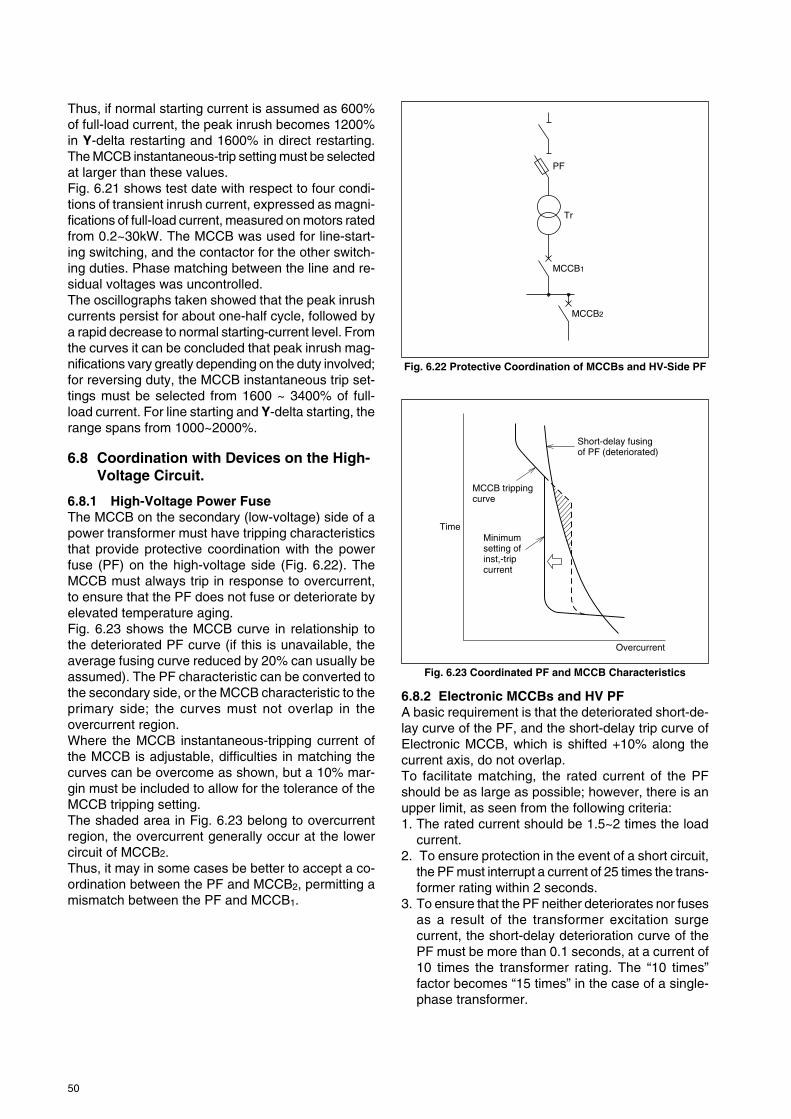
50
Fig. 6.23 Coordinated PF and MCCB Characteristics
6.8.2 Electronic MCCBs and HV PFA basic requirement is that the deteriorated short-de-lay curve of the PF, and the short-delay trip curve ofElectronic MCCB, which is shifted +10% along thecurrent axis, do not overlap.To facilitate matching, the rated current of the PFshould be as large as possible; however, there is anupper limit, as seen from the following criteria:1. The rated current should be 1.5~2 times the load
current.2. To ensure protection in the event of a short circuit,
the PF must interrupt a current of 25 times the trans-former rating within 2 seconds.
3. To ensure that the PF neither deteriorates nor fusesas a result of the transformer excitation surgecurrent, the short-delay deterioration curve of thePF must be more than 0.1 seconds, at a current of10 times the transformer rating. The “10 times”factor becomes “15 times” in the case of a single-phase transformer.
Thus, if normal starting current is assumed as 600%of full-load current, the peak inrush becomes 1200%in Y-delta restarting and 1600% in direct restarting.The MCCB instantaneous-trip setting must be selectedat larger than these values.Fig. 6.21 shows test date with respect to four condi-tions of transient inrush current, expressed as magni-fications of full-load current, measured on motors ratedfrom 0.2~30kW. The MCCB was used for line-start-ing switching, and the contactor for the other switch-ing duties. Phase matching between the line and re-sidual voltages was uncontrolled.The oscillographs taken showed that the peak inrushcurrents persist for about one-half cycle, followed bya rapid decrease to normal starting-current level. Fromthe curves it can be concluded that peak inrush mag-nifications vary greatly depending on the duty involved;for reversing duty, the MCCB instantaneous trip set-tings must be selected from 1600 ~ 3400% of full-load current. For line starting and Y-delta starting, therange spans from 1000~2000%.
6.8 Coordination with Devices on the High-Voltage Circuit.
6.8.1 High-Voltage Power FuseThe MCCB on the secondary (low-voltage) side of apower transformer must have tripping characteristicsthat provide protective coordination with the powerfuse (PF) on the high-voltage side (Fig. 6.22). TheMCCB must always trip in response to overcurrent,to ensure that the PF does not fuse or deteriorate byelevated temperature aging.Fig. 6.23 shows the MCCB curve in relationship tothe deteriorated PF curve (if this is unavailable, theaverage fusing curve reduced by 20% can usually beassumed). The PF characteristic can be converted tothe secondary side, or the MCCB characteristic to theprimary side; the curves must not overlap in theovercurrent region.Where the MCCB instantaneous-tripping current ofthe MCCB is adjustable, difficulties in matching thecurves can be overcome as shown, but a 10% mar-gin must be included to allow for the tolerance of theMCCB tripping setting.The shaded area in Fig. 6.23 belong to overcurrentregion, the overcurrent generally occur at the lowercircuit of MCCB2.Thus, it may in some cases be better to accept a co-ordination between the PF and MCCB2, permitting amismatch between the PF and MCCB1.
Fig. 6.22 Protective Coordination of MCCBs and HV-Side PF
PF
Tr
MCCB1
MCCB2
Time
MCCB tripping curve
Minimum setting ofinst,-trip current
Short-delay fusingof PF (deteriorated)
Overcurrent

51
6.8.3 MCCBs and HV-Side OCRAn overcurrent-relay remote tripping device (OCR) onthe HV side of the circuit must be coordinated withthe MCCBs on the LV side. The OCR setting musttake into consideration the coordination with the OCRat the power-utility substation and, at the same time,the following:1. The setting of an OCR with an instantaneous-trip
element must be at least 10 times the transformercurrent rating, to ensure that the excitation surgeof the latter does not trip the OCR.
2. To ensure short-circuit protection, the OCR mustoperate within 2 seconds, at 25 times thetransformer rated current.
Figs. 6.26 and 6.27 show the setup, and the coordinat-ed characteristics converted to the low-voltage side.The turns ratio of the CT is 150:5, to match the ratedprimary current of 87.5A. Considering cooperation ofthe OCR with the upper-ranking substation OCR, theOCR dial is normally set to 0.2 or less, or 1 secondmax. if it has an instantaneous trip element. On theMitsubishi Type MOC-E general-purpose relay this isequivalent to dial setting No. 2. Latching-curve over-lap, shown by the broken lines in Fig. 6.27, must beallowed for. The instantaneous trip is set to 30A, inaccordance with §1, above.
For setting the Electronic MCCBs (800 and 600A ver-sions of Type NF800-SEW), the short-delay trippingcurrents of both are set to MIN. NF800-SEW havenegligible latching inertia, so that the reset character-istics (except in the instantaneous-trip region) can beregarded as the same as the tripping characteristics.Further, there is very little tolerance variation betweenunits; thus, the tripping characteristics can be shownas a single line.
If the NF800-SEW short-delay trip current is set atMAX (where MIN and MAX respectively correspondto 2 and 10 times rated current), a 600A rating settingwill correspond to 6000A tripping, and an 800A set-ting will correspond to 8000A tripping. In this case (atMAX setting), short-delay latching of the NF800-SEPwill overlap the OCR latching (4710A, secondary con-version). But if the NF800-SEW and the OCR are allset to MIN, so that the latching values do not exceed4710A, good coordination will be achieved.
As the OCR has an instantaneous-trip element, setat 30A (secondary conversion 28.3kA), the region ofselective interruption between the OCR and theNF800-SEW will extend to this value.
Considering the coordination of the ElectronicMCCBs with the lower-level MCCBs (NF250-CW), it
NF250-CW
NF800-SEW800A setting
CT ratio150/5
CT
Tr
OCR
CB or S
Type MOC-E5A tapdial < 2
NF800-SEW600A setting
6.6kV/210V3f1000 kVA
Electronic MCCB
PF
Tr
Fig. 6.25 Coordinated PF and Electronic MCCBCharacteristics
3 h
21 h403020
10 min64
1 min403020
10 s642
1 s
0.6
0.4
0.20.1
0.06
0.020.01
0.0060.0040.002
Short-delay tripping current setting range
Electronic MCCBcharacteristic curve
Deterioratedcurve of PF
150
200
300
400
600
800
1,000 2,000 4,000 6,000 20,000 150,000
10,000 40,000
Current (A rms)
Tim
e
Fig. 6.24 Protective Coordination of Electorinic MCCBsand PF
Fig. 6.26 Electronic MCCBs in Coordination with an HV-Side OCR

52
Fig. 6.27 Coordinated OCR and Electronic MCCB Characteristics
can be seen from Fig. 6.27 that the maximum trip curve(tolerance) of the C Line units matches well with theNF800-SEW curves, with no danger of overlap.
3 h2
1 h403020
10 min
64
2
6
0.60.4
0.2
0.1
0.06
0.02
0.01
0.0060.004
0.002
4
2
1 min
3020
10 s
1 s
Tim
e
150 300 600 1,000 4,000 10,000 40,000 80,000
200 400 800 6,000 20,000 60,0002,000
Current (A, rms)
NF800-SEW800A setting
Max.MOC-E tripping curve CT ratio 150/5 Tap 5 Dial #2
Latching curve
Inst. trip setting 30A
NF250-CW175A
Min.
Max.
Min.

53
Fig. 7.1 MCCB Selection Consideration
Table 7.1 MCCB Deratings Due to InstallationFactors
Panelboard max.internal temp. (°C)
50
55
60
Load allowable, due topanelboard temp. (%)
90
80
70
Supplysystem
Ambienttemperature
Main,submainor branch use
Ambientconditions
Wireconnection
Loadcurrent
Operationconditions
Load
Short circuit
Installation andconnection style
Servicepurpose
Regulations
7. SELECTIONIn selecting MCCBs for a particular application, inaddition to purely electrical aspects of load and distri-bution conductor systems, physical factors such aspanelboard configuration, installation environment,ambient-temperature variations, vibration, etc. mustalso be considered.
MCCBs are rated for an ambient of 40°C, andwhere panelboard internal temperatures may exceedthis, the MCCBs installed should be derated in accor-dance with Table 7.1.1. Actual load currents may exceed the nominal-val-
ues.2. Load currents may increase with time, due to dete-
rioration of load devices (i.e., friction in motors).3. Source voltage and frequency may vary.
7.1 Motor Branch CircuitsThe following discussion assumes single motors andcold-start operation.
7.1.1 General ConsiderationsThe starting current (IMS) and time (TMS) for the mo-tor, and its full-load current, dictate the rated current,long-delay trip and instantaneous-trip curves for theMCCB as shown in Fig. 7.2. A safety-margin of up to50% should be considered for the starting time, toallow for voltage variations and increase in load fric-tion.
The instantaneous-trip curve should be at least 1.4x normal starting current to allow for the effect of theDC component attendant to the low power factor(about 0.3) of the starting current. For -delta start-ing the unphased-switching allowance increases the1.4 margin to 1.9. For running restarting the unphased-switching allowance increases the factor to 2.4.
Rated currents
MCCB trip curve
Starting currentand long-delay trip
Inrush andinst. trip
Motorstartingcurrent
TMS
Current
Tim
e
MS
Fig. 7.2 MCCB and Motor Starting
7.1.2 Motor BreakerWhere starting times are relatively short and currentsare small, the Mitsubishi M Line motor breakers canbe used without the need for a motor starter.
7.2 For Lighting and Heating Branch Cir-cuits
In such circuits, switching-surge magnitudes and timesare normally not sufficient to cause spurious trippingproblems; however, in some cases, such as mercury-arc lamps or other large starting-current equipment,the methods presented in §7.1 above should be con-sidered.
In general, branch MCCBs should be selected sothat the total of ratings of the connected loads is notmore than 80% of the MCCB rating.

54
7.3 For Main Circuits
7.3.1 For Motor LoadsThe method of “synthesized motors” is recommended– that is, the branch-circuit loads to be connected aredivided into groups of motors to be started simulta-neously (assumed), and then each group is regardedas a single motor having a full-load current of the totalof the individual motors in the group. The groups areregarded as being sequentially started.
The rating of the branch MCCB for the largest syn-thesized motor is designated IB max., those of thesubsequent synthesized motors as I1, I2, ...In-1. Therating of the main MCCB becomes:
IMAIN = IB max + (I1 + I2 +...In-1) x D
where D is the demand factor (assumed as 1 if inde-terminate).
7.3.2 For Lighting and Heating, and Mixed LoadsFor lighting and heating loads the rating of the mainMCCB is given as the total of the branch MCCB rat-ings times the demand factor. For cases where bothmotor-load branches and lighting and heatingbranches are served by a common main MCCB, thesummation procedures are handled separately, asdescribed in the foregoing, then grand-totalized to givethe main MCCB rating.
7.4 For Welding Circuits
7.4.1 Spot WeldersA spot welder is characterized by a short, heavy in-termittent load, switched on the transformer primaryside. The following points must be considered inMCCB selection:1. The intermittent load must be calculated in terms
of an equivalent continuous current.2. The excitation transient surge due to the breaker
being on the transformer primary side must be al-lowed for.
MCCBWelder
Weldworkpiece
Controltimer
Supply
Fig. 7.3 Spot-Welder Circuit
The temperature rise of the MCCB and wiring de-pends on the thermal-equivalent continuous current.To convert the welder intermittent current into a ther-mal-equivalent continuous value (Ie), consider thecurrent waveform (Fig. 7.4); load resistance (R) givespower dissipation:
W = I12 Rt1
and average heat produced:
t1 + t2W
=t1 + t2 Rt1 = 12 Rβ = R( 1 β )221
where β is the duty factor, defined as
total conduction timetotal time
This is equivalent to heating by a continuous current of
.In the example of Fig. 7.4:
e = 1 β = 1200 x 0.0625 = 300 (A)i.e., a continuous current of 300A will produce theaverage temperature. In practice, however, the instan-taneous temperature will fluctuate as shown in Fig.7.5 and the maximum value (Tm) will be greater thanthe average (Te) that would be produced by a con-tinuous current of 300A. The operation of an MCCBthermal element depends on the maximum rather thanthe average temperature, so it must be selected notto trip at Tm; in other words, it is necessary to ensurethat its hot-start trip delay is at least as great as theinterval of current flow in the circuit. The rated currentof a “mag-only” MCCB (which does not incorporate athermal trip function) can be selected based on thethermal equivalent current of the load, allowing amargin of approximately 15% to the calculated valueto accommodate supply-voltage fluctuations, equip-ment tolerance, etc. Thus:
IMCCB = Ie x 1.15 = 300 x 1.15 = 345 (A)
The MCCB selected becomes the nearest standardvalue above 345A.
Time
(Duty factor = =0.0625)
Current
t1 t2
(3sec.) (45sec.)
3+453
Fig. 7.4 Welder Intermittent Current
Time
Te
Tm
Tem
pera
ture
Fig. 7.5 Temperature Due to Intermittent Current
For practical considerations, rather than basingselection on welding conditions, the MCCB should beselected to accommodate the maximum possible duty,based on the capacity and specifications of the welder.
If the welder rated capacity, voltage and duty fac-tor in Fig. 7.3 are 85kVA, 200V and 50% respectively,the thermal-equivalent continuous current (Ie) be-
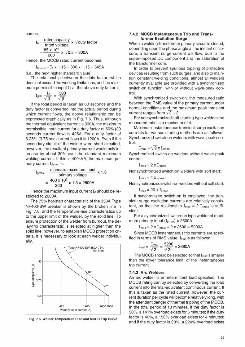
55
comes:
rated voltagerated capacity
x duty factor
=200
85 x 103x 0.5 = 300A
Hence, the MCCB rated current becomes:
IMCCB = Ie x 1.15 = 300 x 1.15 = 345A
(i.e., the next higher standard value).The relationship between the duty factor, which
does not exceed the working limitations, and the maxi-mum permissible input Iβ at the above duty factor is:
β β300
=βe
If the total period is taken as 60 seconds and theduty factor is converted into the actual period duringwhich current flows, the above relationship can beexpressed graphically as in Fig. 7.6. Thus, althoughthe thermal equivalent current is 300A, the maximumpermissible input current for a duty factor of 50% (30seconds current flow) is 425A. For a duty factor of6.25% (3.75 sec current flow) it is 1200A. Even if thesecondary circuit of the welder were short circuited,however, the resultant primary current would only in-crease by about 30% over the standard maximumwelding current. If this is 400kVA, the maximum pri-mary current Iβmax is:
primary voltagestandard maximum input
x 1.3
200400 x 103
x 1.3 = 2600A
β
Hence the maximum input current Iβ should be re-stricted to 2600A.
The 75% hot-start characteristic of the 350A TypeNF400-SW breaker is shown by the broken line inFig. 7.6, and the temperature-rise characteristics upto the upper limit of the welder, by the solid line. Toensure protection of the welder from burnout, the de-lay-trip characteristic is selected at higher than thesolid line; however, to establish MCCB protection cri-teria, it is necessary to look at each welder individu-ally.
Ope
ratin
g tim
e (s
)
30
3.75
0.6
425Primary input current (A)
Type NF400-SW·350A 75%hot start
10"
2"
300026001200
Fig. 7.6 Welder Temperature Rise and MCCB Trip Curve
7.4.2 MCCB Instantaneous Trip and Trans-former Excitation Surge
When a welding-transformer primary circuit is closed,depending upon the phase angle at the instant of clo-sure, a transient surge current will flow, due to thesuper-imposed DC component and the saturation ofthe transformer core.
In order to prevent spurious tripping of protectivedevices resulting from such surges, and also to main-tain constant welding conditions, almost all welderscurrently available are provided with a synchronizedswitch-on function, with or without wave-peak con-trol.
With synchronized switch-on, the measured ratiobetween the RMS value of the primary current undernormal conditions and the maximum peak transientcurrent ranges from 2 ~ 2.
For nonsynchronized soft-starting-type welders themeasured ratio is a maximum of 4.
Maximum instantaneous transient surge excitationcurrents for various starting methods are as follows:Synchronized switch-on welders with wave peak con-trol:
max = 2 x maxβ
Synchronized switch-on welders without wave peakcontrol:
Imax = 2 x Iβmax
Nonsynchronized switch-on welders with soft start:
Imax = 4 x Iβmax
Nonsynchronized switch-on welders without soft start:
Imax = 20 x Iβmax
If synchronized switch-on is employed, the tran-sient surge excitation currents are relatively consis-tent, so that the relationship Imax = 2 Iβmax is suffi-cient.
For a synchronized switch-on type welder of maxi-mum primary input (Iβmax) = 2600A
Imax = 2 x Iβmax = 2 x 2600 = 5200A
Since MCCB instantaneous trip currents are speci-fied in terms of RMS value, Iinst is as follows:
2= 3680A
25200
=instmax
The MCCB should be selected so that Iinst is smallerthan the lower tolerance limit, of the instantaneoustrip current.
7.4.3 Arc WeldersAn arc welder is an intermittent load specified. TheMCCB rating can by selected by converting the loadcurrent into thermal-equivalent continuous current. Ifthis is taken as the rated current, however, the cur-rent duration per cycle will become relatively long, withthe attendant danger of thermal tripping of the MCCB.In the total period of 10 minutes, if the duty factor is50%, a 141% overload exists for 5 minutes; if the dutyfactor is 40%, a 158% overload exists for 4 minutes;and if the duty factor is 20%, a 224% overload exists
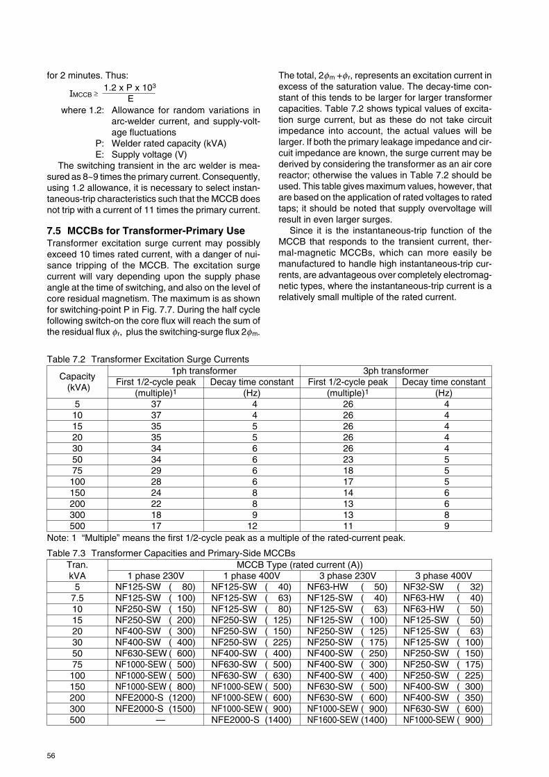
56
for 2 minutes. Thus:
E1.2 x P x 103
MCCB ≥
where 1.2: Allowance for random variations inarc-welder current, and supply-volt-age fluctuations
P: Welder rated capacity (kVA)E: Supply voltage (V)
The switching transient in the arc welder is mea-sured as 8~9 times the primary current. Consequently,using 1.2 allowance, it is necessary to select instan-taneous-trip characteristics such that the MCCB doesnot trip with a current of 11 times the primary current.
7.5 MCCBs for Transformer-Primary UseTransformer excitation surge current may possiblyexceed 10 times rated current, with a danger of nui-sance tripping of the MCCB. The excitation surgecurrent will vary depending upon the supply phaseangle at the time of switching, and also on the level ofcore residual magnetism. The maximum is as shownfor switching-point P in Fig. 7.7. During the half cyclefollowing switch-on the core flux will reach the sum ofthe residual flux fr, plus the switching-surge flux 2fm.
The total, 2fm +fr, represents an excitation current inexcess of the saturation value. The decay-time con-stant of this tends to be larger for larger transformercapacities. Table 7.2 shows typical values of excita-tion surge current, but as these do not take circuitimpedance into account, the actual values will belarger. If both the primary leakage impedance and cir-cuit impedance are known, the surge current may bederived by considering the transformer as an air corereactor; otherwise the values in Table 7.2 should beused. This table gives maximum values, however, thatare based on the application of rated voltages to ratedtaps; it should be noted that supply overvoltage willresult in even larger surges.
Since it is the instantaneous-trip function of theMCCB that responds to the transient current, ther-mal-magnetic MCCBs, which can more easily bemanufactured to handle high instantaneous-trip cur-rents, are advantageous over completely electromag-netic types, where the instantaneous-trip current is arelatively small multiple of the rated current.
Table 7.2 Transformer Excitation Surge Currents
Capacity (kVA)
5101520305075100150200300500
Decay time constant(Hz)
444445556689
First 1/2-cycle peak(multiple)1
373735353434292824221817
Decay time constant(Hz)
44556666889
12
First 1/2-cycle peak(multiple)1
262626262623181714131311
1ph transformer 3ph transformer
Table 7.3 Transformer Capacities and Primary-Side MCCBsTran.kVA
57.5101520305075100150200300500
3 phase 400VNF32-SW ( 32)NF63-HW ( 40)NF63-HW ( 50)NF125-SW ( 50)NF125-SW ( 63)NF125-SW ( 100)NF250-SW ( 150)NF250-SW ( 175)NF250-SW ( 225)NF400-SW ( 300)NF400-SW ( 350)NF630-SW ( 600)NF1000-SEW ( 900)
MCCB Type (rated current (A))1 phase 230V
NF125-SW ( 80)NF125-SW ( 100)NF250-SW ( 150)NF250-SW ( 200)NF400-SW ( 300)NF400-SW ( 400)NF630-SEW ( 600)NF1000-SEW ( 500)NF1000-SEW ( 500)NF1000-SEW ( 800)NFE2000-S (1200)NFE2000-S (1500)
—
1 phase 400VNF125-SW ( 40)NF125-SW ( 63)NF125-SW ( 80)NF250-SW ( 125)NF250-SW ( 150)NF250-SW ( 225)NF400-SW ( 400)NF630-SW ( 500)NF630-SW ( 630)NF1000-SEW ( 500)NF1000-SEW ( 600)NF1000-SEW ( 900)NFE2000-S (1400)
3 phase 230VNF63-HW ( 50)NF125-SW ( 40)NF125-SW ( 63)NF125-SW ( 100)NF250-SW ( 125)NF250-SW ( 175)NF400-SW ( 250)NF400-SW ( 300)NF400-SW ( 400)NF630-SW ( 500)NF630-SW ( 600)NF1000-SEW ( 900)NF1600-SEW (1400)
Note: 1 “Multiple” means the first 1/2-cycle peak as a multiple of the rated-current peak.

57
Core saturationflux
φr
PNormal flux
Transient flux
Surge current
Voltage
2φm+φR
Fig. 7.7 Excitation Surge Effects
In MC CB selection for 400V, 50kVA transformer-primary used, rated RMS current is:
3 x Voltage (V)Capacity (kVA) x 103
= 72.2A3 x 400
50 x 103=
From Table 7.2, the peak value of the excitation surgecurrent Iφ is 23 times that of the rated current, hence:
φ =23 x 2 = 23 x 2 x 72.2A = 2348AThus the MCCB selected should have instantaneoustrip current of no less than 2348A. The Type NF250-SW 150A MCCB, with:
inst = 2 x 150 x 11.2 = 2376Asatisfies the above condition. Thus the 3-pole versionof this type is suitable for this application.
Examples of MCCBs selected in this way are shownin Table 7.3; it is necessary to confirm that the short-circuit capacities of the breakers given are adequatefor the possible primary-side short-circuit current ineach case.
7.6 MCCBs for Use in Capacitor (PF Cor-rection) Circuits
The major surge tendency results from circuit open-ing due to the leading current. If the capacitor circuitof Fig. 7.8 is opened at time t1 in Fig. 7.8, arc extinc-tion will occur at time t2, the zero-point of the leadingcurrent (i). Subsequently the supply-side voltage (Vt)will vary normally, but the load-side voltage (Vc) willbe maintained at the capacitor charge value. The po-tential difference (Vc-Vt) will appear across the MCCBcontacts and at time t3, approximately 1/2-cycle aftert2, will become about twice the peak value of the sup-ply voltage (Em). If the MCCB contacts are not suffi-ciently open, an arc will reappear across the gap, re-sulting in an oscillatory capacitor discharge (at a fre-quency determined by the circuit reactance, includ-ing the capacitor) to an initial peak-to-peak amplitudeof 4Em. When the arc extinguishes, Vc will once againbe maintained at a potential of –Em and the potentialdifference across the MCCB contacts will increaseagain. This cycle will repeat until the gap between thecontacts becomes too great, and the interruption willbe completed.
Since Mitsubishi MCCBs exhibit extremely rapidcontact separation, repetitive arcing is virtually non-
existent; however, some MCCBs do not make andbreak so rapidly, and in such cases, if the load ca-pacitance is large enough, they will not dischargequickly, and if the arc extinguishes near the peak ofthe reverse-going oscillation voltage, the capacitorvoltage will be maintained in the region of –3Em bythe first restriking of the arc; at the second restrike itwill become 5Em, on the third –7Em, etc., ultimatelyleading to breakdown of the capacitor. Thus, rapidswitching is essential in leading power-factor circuits.
In selecting an MCCB, first consider the surge cur-rent. If the supply voltage is V volts, the capacitor Cfarads, the frequency f Hertz and the current Ι amp,the kVA rating (P) becomes:
For a three-phase system:
1000 P = 3 V = 2πfCV2
For a single-phase system:1000 P = V = 2πfCV2
Vt Vc C
Fig. 7.8 Capacitor Circuit
Vt
VcVci
Vct1 t2
t3
Em
Em
Fig. 7.9 Circuit-Opening Conditions
VtVc = Em
Vc = –3Em
Vc = –7Em
Vc = 5Em
Circuitopening
Fig. 7.10 Accumulative Capacitor Charge
When the switch (Fig. 7.11) is closed, a charge(q=CV) must be instantaneously supplied to equal the

58
instantaneous supply voltage (V), according to thephase angle at the instant of circuit closure. Thischarge results in a large surge current. If the circuit isclosed at the peak (Em) of the supply voltage (V), thesurge current (i), according to transient phenomenatheory, is:
2 Emi =t
2LR
–ε
C4L
– R2 2Lsin tC
4L– R2
From Fig. 7.12, the maximum value (im) is:
Emim =
R–
ε
CL
Rarctan C
C
4L– R2
4L– R2
and appears at time t = t0 where:
2Lt0 =R
arctan C
C
4L– R2
4L– R2
Although V is not constant, τ0 is extremely small, sothat V = Em can be assumed for the transient dura-tion; similarly, the conduction time can be assumedas 2τ0. Thus, an MCCB for use in a capacitive circuitmust have an instantaneous-trip current of greaterthan im x 2τ0.
Example: MCCB selection for a 3-phase 230V 50Hz150 kVA capacitor circuit.
From Table 7.4, C = 0.9026 x 10⁻² (F) and I =377(A).
The values of R and L in the circuit must be esti-mated, and for this purpose it is assumed that theshort-circuit current is approximately 100 times thecircuit capacity – i.e., 50,000A.
Z = R2 + (2πfL)2 ∴ 50,000 =3 ZV
thus: Z = = 2.66 x 10⁻³
3 x 50,000230
since: Em =
obtained from their respective formulas as,
V = 188, im and τ0 can be 32
and assuming:
then: 2πfL = 2.60 x 10⁻³ Ω
thus: R = 5.21 x 10⁻⁴ Ω L = 8.29 x 10⁻⁶ (H)
= 5R
2πfL
im =6200Aτ0 = 4.27 x 10⁻⁴ (s).
Since current-flow duration is approximately 2τ0,an MCCB is selected with a latching time of 0.001seconds at 6200A. The Type NF630-SW is suitable,having a latching time of 0.0029 seconds at 10,000A.Even with a shorter latching time, tripping is unlikely
under the application of the above current, but selec-tion of an MCCB with an instantaneous-trip current ofgreater than M2
6200 = 4400A is recommended for an ad-equate safety margin. Such an MCCB will be rated at600A. Accordingly, in this example the Type NF630-SW, rated at 600A, is selected. Table 7.4 is a basisfor selection, but since, in cases where the short-cir-cuit capacity of the circuit is considerably higher thanthat of the MCCB, spurious tripping due to the switch-ing surge may occur, it is also necessary to make cal-culations along the lines of the above example.
Em Vc
i L R
C
Fig. 7.11 PF Correction Capacitor
Vc
i
im
τo
FIg. 7.12 Currents and Voltages
7.7 MCCBs for Thyristor CircuitsBoth overcurrent and overvoltage protection must beprovided for these elements. MCCBs can be usedeffectively for overcurrent, although application de-mands vary widely, and selection must be made care-fully in each case. Overvoltage protection must beprovided separately; devices currently in use includelightning arresters, dischargers, RC filters and oth-ers.1. MCCB Rated CurrentsA primary factor determining the rated current of theMCCB to be used is the question of AC-side or DC-side installation. AC-side installation permits a lowerrating, which is a considerable advantage. Fig. 7.13shows both AC and DC installation (MCCBs 1 and 2);Table 7.5 gives a selection of circuit formats and cur-rent configurations; using this table it is possible todetermine the MCCB rating for either MCCB 1 or 2,as required. The current curve of the thyristor (aver-age current is usually given) and the tripping curve ofthe MCCB should be rechecked to ensure that thereis no possibility of overlap.
When an overcurrent is due to a fault in the load,causing a danger of thermal destruction of the circuitelements, either AC or DC protection is adequate,provided the parameters are properly chosen. Whenthe fault is in one of the thyristor elements, resulting

59
Table 7.4 MCCB Selection for Circuits with PF-Correctiona) 230V, 50Hz CircuitCapacitor rating
kvar
51015202530405075100150200300400
µF
30160290312031504180524073009451360179026
120341805224069
Single-phase circuit
Capacitorrated
current(A)
21.743.565.287.0108.7130.4173.9217.4326.1434.8652.2869.61304.31739.1
MCCBrated
current(A)4075
1001251752002503505007001000140020002500
Three-phase circuit
Capacitorrated
current(A)
12.625.137.750.262.875.3100.4125.5188.3251.0376.5502.0753.11004.1
MCCBrated
current(A)2040638010012515020030040060080012001500
b) 230V, 60Hz CircuitCapacitor rating
kvar
51015202530405075100150200300400
µF
25150175210031254150420062507376150147522
100291504320057
Single-phase circuit
Capacitorrated
current(A)
21.743.565.287.0108.7130.4173.9217.4326.1434.8652.2869.61304.31739.1
MCCBrated
current(A)4080
1001251752002503505007001000140020002500
Three-phase circuit
Capacitorrated
current(A)
12.625.137.750.262.875.3100.4125.5188.3251.0376.5502.0753.11004.1
MCCBrated
current(A)2040638010012515020030040060080012001500
Capacitor rating
kvar
51015202530405075100150200300400
µF
99199298398497597796995149219892984397959687958
Single-phase circuit
Capacitorrated
current(A)
12.525.037.550.062.575.0100.0125.0187.5250.0375.0500.0 750.01000.0
MCCBrated
current(A)2040638010012515020030040060080012001500
Three-phase circuit
Capacitorrated
current(A)7.214.421.728.936.143.357.772.2
108.3144.3216.5288.7433.0577.4
MCCBrated
current(A)153240506380100125175225350500700900
c) 400V, 50Hz Circuit
ture rise of the thyristor junction, resulting in loss ofthe control function, and thermal destruction. A fault,therefore, must be interrupted as quickly as possible,before the junction temperature rises above its speci-fied limit. In the overcurrent region, designated on thecurrent-surge withstand curves of the circuit element,the element can usually withstand the surge for atleast one cycle. The current-surge withstand, gener-ally specified as a peak value, must be converted toRMS, to select a suitable MCCB.
An overload of short-circuit proportion, either ex-ternal or in a bridge-circuit thyristor element, necessi-tates rapid interruption of the circuit. Normally, such
d) 400V, 60Hz CircuitCapacitor rating
kvar
51015202530405075100150200300400
µF
83166249332414497663829124316582487331649746631
Single-phase circuit
Capacitorrated
current(A)
12.525.037.550.062.575.0100.0125.0187.5250.0375.0500.0750.01000.0
MCCBrated
current(A)2040638010012515020030040060080012001500
Three-phase circuit
Capacitorrated
current(A)7.214.421.728.936.143.357.772.2
108.3144.3216.5288.7433.0577.4
MCCBrated
current(A)153240506380100125175225350500700900
in reverse current, the result is often that other circuitelements will be destroyed (see Fig. 7.14) if the cir-cuit is not interrupted immediately. In this case AC-side protection or protection in series with each ele-ment is necessary.2. Tyristor Overcurrent ProtectionTotal protection of each element is possible in theory,but in practice overall coordination and the best com-promise for economy are usually demanded. Whereelements are critical, complex combinations of pro-tective devices can be employed, at proportionallyhigher cost.
Basically, overcurrent leads to excessive tempera-
Notes: 1. The MCCB rated current should be approx. 150% of the capacitor rated current.2. The MCCB short-circuit capacity should be adequate for the circuit short-circuit capacity.

60
Circuit No. I Circuit No. II Circuit No. III Circuit No. IV
Element average current
Element RMS current
Average DC current
RMS current
Current waveform
Current waveform
Circuit diagram
Cur
rent
flow
MC
CB
1M
CC
B2
2 2
2
26 +1
4π
3 +π1
2π
3 +1
3π
2π
or2π
π π π π
2 3
3
2π
or2π
4π
or
π
πor
2 +π1
4π
2 +1
3π
4π
or
2π
or
π
πor
π
2 2
2 2
2
2 2π
or
F (A)
e (A)
D (A)
B (A)
B (A)
( 2.22 )( 2.45 )
( 0.552 )
( 1.11 )
( 0.817 )
22
3 3
3 3
3
3
3
Load
MCCB1
MCCB1
MCCB2
Load
MCCB1
MCCB2
Load
MCCB1
MCCB2
Load
P P P P
D D D D D
D D D D
D
D
F
P P P P
P P P P
F F F F
F
F F FF
P
F
F FF
e
P P
P P
RMS current
Load
MCCB1
MCCB2
Load
Faultelement
Note: Load is assumed resistive, with elements conductive through 180°.
Table 7.5 Thyristor Circuits and Current Formats
Fig. 7.13 AC- and DC-side Protectors for Thyristors Fig. 7.14 Fault-Current Flow

61
DC-protection case (MCCB2) can be plotted in thesame way.
Region 2 in Fig. 7.17 is the area of overcurrent forwhich protection is effected by the MCCB. For pro-tection of region 1, an overload relay is effective, andfor region 2, inductance L must be relied on to limitthe fault-current rise rate, or a high-speed current-lim-iting fuse must be used. Practical considerations, in-cluding economy and the actual likelihood of faults inthe regions concerned, may dictate the omission ofthe protective devices for regions 1 and 3, in manycases. The lower the instantaneous-trip setting of theMCCB, the wider the region 2 coverage becomes.
MCCB2
MCCB1
L
Smoothing inductance
R
E
Shortcircuit
Load
Fig. 7.15 Thyristor Short Circuit
MCCB
Short-circuit current
Trip current
q
Arc voltage
Circuit voltage
t1 t3
t2 t4
tT
t1 : Time to MCCB latching t2 : MCCB opening time t3 : Time from contact parting to current peak valuet4 : Arc durationtT : Total interruption time q : Current-rise rate
Fig. 7.16 Thyristor Short-Circuit Interruption
interruption takes place within one cycle; thus, fromthe point of view of element thermal destruction, thetime integral of the current squared must be consid-ered. Quantitatively, the permissible i2dt of the ele-ment must be greater than the i2dt of the MCCB cur-rent through interruption, converted to apply to theelement. The latter is influenced by the short-circuitcurrent magnitude, the interruption time, and the cur-rent-limiting capability of the MCCB.
It is important to note that the MCCB interruptiontime will be considerably influenced by the short-cir-cuit current rise rate, di/dt, on the load side. In theshort circuit of Figs. 7.15 and 7.16, the current is:
i = (1 – ε )RE – t
LR
and the current rise rate di/dt is:
( ) t=0 =dtdi
LE
Thus, the inductance of the line, and the smoothinginductance significantly affect di/dt. Where the poten-tial short-circuit current is very large, the inductanceshould be increased, to inhibit the rise rate and assistthe MCCB to interrupt the circuit in safe time. This isillustrated in Fig. 7.17, for MCCB2 of Fig. 7.15.
The MCCB current during total time (tT) is i2 dt,which, converted to the i2 dt applied to the circuitelement, must be within the limit specified. Havingdetermined the circuit constants, testing is preferableto calculation for confirmation of this relationship.
Assuming a large current-rise rate, with an AC-sideshort-circuit current i = Ipssin ωt, and an MCCB inter-ruption time of one cycle, the i2 dt applied to the thy-ristor is as follows:1. For circuits I, II and III of Table 7.10:
i2dt = p2 sin2 ωtdt = p24f12f
1
0(A2s)
2. For circuit IV:
i2dt = 2 p2 sin2 ωtdt = ( )+ (A2s)f
p2
61
4π33f
1
6f1
where Ip is the peak value of the element current andf is the supply frequency.
If the i2 dt of the circuit element is known, the per-missible i2dt for the MCCB can be determined, us-ing the last two equations given above. Provided thatthe interruption time is not greater than one cycle, theMCCB current will be the same as the element cur-rent for circuits I and II, and twice that for circuits IIIand IV. This means that the MCCB i2dt through theinterruption time should be within twice the permis-sible i2dt of the element.
Diodes are generally stronger against overcurrentthan thyristors, and since diodes can handle largerI2·t, protection is easier.
Fig. 7.17 shows the protection coordination situa-tion of a selection of devices, plotted together withthe thyristor current-surge withstand curve. AC-sideprotection (MCCB1, Fig. 7.15) is presented, but the

62
Fig. 7.18 Ward-Leonard Thyristor Protection
Fig. 7.17 Thyristor and Protector Operating Curves
M
Short-circuit path in a commutation element failure
Short-circuit path in a power outage
Commutation element failure
3-Phase Fullwave Rectification MCCB: Mag-Only
Trip
ping
tim
e
h
min
s
100
2
1
30201410864
2
1
3020
10
5
2
1
0.5
0.2
0.1
0.05
0.02
0.01
125 200 300 400 500 600700 1000 1500 2000 3000 4000
Current (% of rating)
Region 1
Region 2
Region 3
Thyristor current-surge withstand
MCCB tripping
High-speed current-limiting fuse
Overcurrent-relay
3. Element Breakdown in Thyristor-Leonard SystemsIn this system of DC motor control, if power outage orcommutation failure due to a thyristor control-circuitfault occurs during inversion (while motor regenera-tive power is being returned to the AC supply), theDC motor, acting as a generator while coasting, willbe connected to a short-circuit path, as in Fig. 7.18.For thyristor protection, MCCBs must be placed in theDC side, as shown.
A Mag-Only MCCB with a tripping current of about3 times the rated current is employed, either 3- or 4-pole, series-connected as shown in Fig. 7.20. Sincethe element short-circuit current is the same as theMCCB current, circuit protection is effected providedthat the i2dt limit for the element is larger than thatfor the MCCB interruption duration. This must be es-tablished by test.
Fig. 7.19 High-Speed Fuses for Thyristor-Circuit Protection Fig. 7.20 Series Connection of MCCB Poles
ACsupply
High-speed fuses
MM
M
b) 4-pole MCCB a) 3-pole MCCB

63
Fig. 7.19 shows connection of high-speed fusesfor protection against thyristor breakdown that wouldotherwise result in short-circuit flow from the AC sup-ply side.4. MCCBs for Lamp Mercury-Lamp CircuitsThe ballasts (stabilizers) used in this type of lampcover a variety of types and characteristics. For 200Vapplications (typical), choke-coil ballasts are used. For100V applications a leakage-transformer ballast is em-ployed. Normal ballasts come in low power-factorversions and high power-factor versions, with correc-tion capacitors. More sophisticated types include theconstant-power (or constant-output) type, which main-tains constant lamp current both in starting and nor-mal running, and flickerless types, which minimize theflicker attendant on the supply frequency.
In selecting an MCCB where normal (high or lowPF) ballasts are to be used, the determining factor isthe starting current, which is about 170% of the stablerunning current. In the cases of constant-power orflickerless types, the determining factor is the normalrunning current, which is higher than the starting cur-
rent. For MCCB selection, the latter types can be re-garded as lighting and heating general loads, as pre-viously discussed.
For selection of MCCBs for regular ballasts, the170% starting current is assumed to endure for amaximum of 5 minutes. MCCBs of 100A or less framesize have a tripping value very close to rating for over-loads of duration of this order, so that the MCCB rat-ing should be the nearest standard value above 170%of the stable running current. MCCBs of above 100Aframe size can handle a current of around 120% ofthe rating for 5 minutes without tripping; thus the near-est standard MCCB rating above 1.2
1.7 = 1.4 times thestable-running current of the lamp load is the suitableprotector.
As an example, consider MCCB selection for 10units of 100W, 100V, 50Hz general-purpose highpower-factor mercury lamps. The stable-running cur-rent per lamp is 1.35A. Thus:
1.35 x 10 x 1.7 = 23A, and the selection becomesNF32-SW, 32A rated.

64
7.8 Selection of MCCBs in inverter circuit
7.8.1 Cause of distorted-wave currentDistorted-wave current is caused by factors such as the CVCF device of a computer power unit, various recti-fiers, induction motor control VVVF device corresponding to more recent energy-saving techniques, etc, whereinthyristor and transistor are used. Any of these devices generates DC power utilizing the switching function of asemiconductor and, in addition, transforms the generated DC power into intended AC power. Generally, a largecapacity capacitor is connected on its downstream side from the rectification circuit for smoothing the rectifica-tion, so that the charged current for the capacitor flows in pulse form into the power circuit. Because voltage ischopped at high frequency in AC to DC transforming process, load current to which high frequency current wassuperimposed by chopping basic frequency flows into the load line. This paragraph describes the VVVF in-verter, of these devices, which will develop further as main control methods for induction motors currently inbroad use in various fields . Fig. 7.27 illustrates an example of MCCBs application to inverter circuit. Twocontrol methods of PAM (Pulse Amplitude Modulation) and PWM (Pulse Wide Modulation) are available for theVVVF inverter and generating higher harmonic wave components differs depending on the difference betweenthe control methods. As seen from Tables 7.9 and 7.10, this harmonic wave component of input current can bemade smaller (improved) by inputting DC reactor (DCL) or AC reactor (ACL). Further, in the case of the outputcurrent waveform in Fig. 7.29, the PWM generates higher harmonic wave components than that of the PAM.
This table is subject to the current which meets thefollowing requirements.
Fig.7.27 Example of MCCBs Application to Inverter Circuit
Notes: 1. The characteristics of hydraulic-magnetic type MCCBs vary significantly depending on wave distor-tion. Therefore, use of thermal-magnetic type MCCBs is recommended.
Table 7.8 Reduction Rate
Distortion factor =
RMS value of total harmonic wave component
RMS value of basic frequencyx 100 100% or less
Peak factor = Peak value
RMS value 3 or less
Higher harmonic wave components are mainly No.7 or a lower harmonic wave.
MCCBs tripping system
Thermal-magnetic (bimetal system) 1.4
1.4
1.4
(Note 1) Hydraulic-magnetic
Electronic (RMS value detection)
Reduction rate K
7.8.2 Selection of MCCBsMCCBs characteristic variations and temperature rises dependent on distortion of the current wave must beconsidered when selecting MCCBs for application to an inverter circuit (power circuit). The relation of ratedcurrent IMCCB to load current I of MCCBs is selected as follows from the MCCBs tripping system.
Thermal-magnetic type (bimetal system) and electronic type (RMS value detection) are both RMS currentdetection systems which enable exact overload protection even under distorted-wave current. Due to the aboveexplanation, it is advantageous to select RMS current detection type MCCBs.
MCCB K x
MCCB
M
Inverter
Induction motor
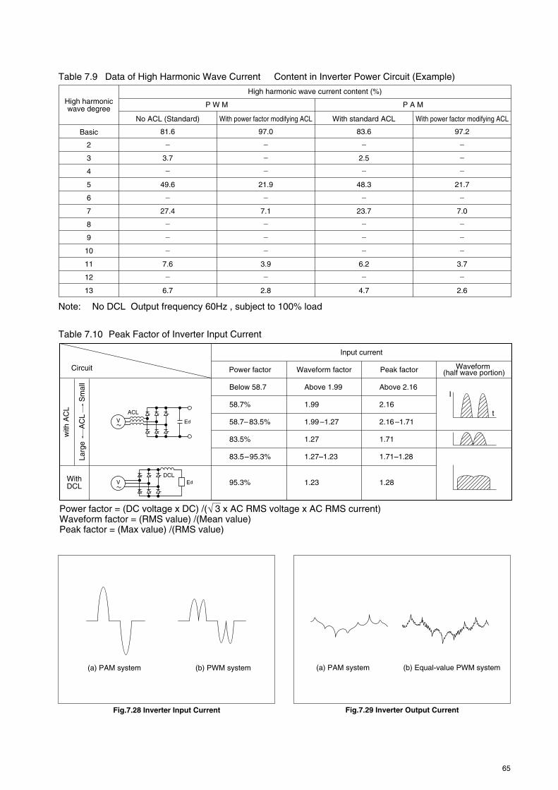
65
High harmonic wave degree
High harmonic wave current content (%)
P W M
No ACL (Standard)
Basic
2
3
4
5
6
7
8
9
10
11
12
13
_
_
_
_
_
_
_
3.7
81.6
49.6
27.4
7.6
6.7
_
_
_
_
_
_
_
2.5
83.6
48.3
23.7
6.2
4.7
_
_
_
_
_
_
_
_
97.0
21.9
7.1
3.9
2.8
_
_
_
_
_
_
_
_
97.2
21.7
7.0
3.7
2.6
With power factor modifying ACL With power factor modifying ACLWith standard ACL
P A M
Power factor = (DC voltage x DC) /( 3 x AC RMS voltage x AC RMS current)Waveform factor = (RMS value) /(Mean value)Peak factor = (Max value) /(RMS value)
Circuit
with
AC
L
Larg
e
AC
L
Sm
all
With DCL
Input current
Power factor
Below 58.7
58.7%
58.7– 83.5%
83.5%
83.5–95.3%
95.3% 1.23 1.28
Above 1.99
1.99
1.99 –1.27
1.27
1.27–1.23
Above 2.16
2.16
2.16 –1.71
1.71
1.71–1.28
Waveform factor Peak factor Waveform (half wave portion)
t
I
ACL
V Ed
DCLV Ed
Table 7.9 Data of High Harmonic Wave Current Content in Inverter Power Circuit (Example)
Table 7.10 Peak Factor of Inverter Input Current
Note: No DCL Output frequency 60Hz , subject to 100% load
Fig.7.28 Inverter Input Current Fig.7.29 Inverter Output Current
(a) PAM system (b) PWM system (a) PAM system (b) Equal-value PWM system

66
8. ENVIRONMENTAL CHARACTERISTICS
Table 8.1 Abnormal Environments, and Countermeasures
8.1 Atmospheric EnvironmentAbnormal environments may adversely affect perfor-mance, service life, insulation and other aspects ofMCCB quality. Where service conditions differ sub-stantially from the specified range as below, deratingof performance levels may result.1. Ambient temperature range –10˚C~+40˚C (Average
temperature for 24 hours,however, shall not behigher than 35˚C.)
2. Relative humidity 85% max. with no dewing3. Altitude 2,000m max.4. Ambient No excessive water or oil
vapour, smoke, dust, saltcontent, corrosive sub-stance, vibration, and im-pactExpected service life(MTTF) under the aboveconditions is 15 years.
8.1.1 High Temperature ApplicationTo comply with relevant standards, all circuit break-ers are calibrated at 40˚C. If the circuit breaker is tobe used in an environment where the ambient tem-perature is likely to exceed 40˚C please apply the de-rating factor shown in table 8.2.For example: To select a circuit breaker for use on asystem where the full load current is 70A in an ambi-ent temperature at 50˚C then from table 8.2
0.970A = 77.8A
Select a circuit breaker with a trip unit adjustable from80-100A or fixed at 100A.
Table 8.2 MCCB DeratingAmbient Temperature (°C)
505560
Derating factor0.90.80.7
High temperature
Low temperature
High humidity
High altitude
Dirt and dust
Corrosive gas, salt air
Environment Trouble Countermeasures
1. Nuisance tripping2. Insulation deterioration
1. Condensation and freezing2. Low-temperature fragility in shipping
(around –40˚C)
1. Insulation resistance loss2. Corrosion
1. Reduced temperature, otherwise no problem up to 2,000m
1. Contact discontinuity2. Impaired mechanism movement3. Insulation resistance loss
1. Corrosion
1. Reduce load current (derate).2. Avoid ambients above 60˚C.
1. Install heater for defrosting and drying. 2. Ship tripped, or if not possible, OFF.
1. Use MCCB enclosure such as Type W. 2. Inspect frequently, or install high-
corrosion-resistant MCCBs.
1. See “Low temperature”, above.
1. Use Type MCCB enclosure.
1. Use Type W MCCB enclosure or install high-corrosion-resistant MCCBs.
5:

67
8.1.2 Low Temperature ApplicationIn conditions where temperatures reach as low as–5˚C special MCCBs are usually required. Mitsubishi,however, have tested their standard MCCBs to tem-peratures as low as –10°C without any detrimentaleffects.
For conditions where temperatures drop below–10˚C special MCCBs must be used.
If standard MCCBs experience a sudden changefrom high temperature, high humidity conditions to lowtemperature conditions, there is a possibility of iceforming inside the mechanism. In such conditions werecommend that some form of heating be made avail-able to prevent mal-operation.
In conditions of low temperature MCCBs shouldbe stored in either the tripped or OFF position.
Low Temperature MCCBsSpecial low temperature MCCBs are available thatcan withstand conditions where temperatures fall toas low as –40˚C. These special MCCBs are availablein sizes up to 1200A in the standard series and above50A in the compact series.
8.1.3 High HumidityIn conditions of high humidity the insulation resistanceto earth will be reduced as will the electrical life.
For applications where the relative humidity ex-ceeds 85% the MCCB must be specially prepared orspecial enclosures used. Special preparation includesplating all metal parts to avoid corrosion and specialpainting of insulating parts to avoid the build up ofmildew.
There are two degrees of tropicalisation:Treatment 1- painting of insulating material to avoid
build up of mildew plus special platingof metal parts to avoid corrosion.
Treatment 2- painting of insulating material to avoidbuild up of mildew only.
8.1.4 Corrosive AtmospheresIn the environment containing much corrosive gas, itis advisable to use MCCB of added corrosion resis-tive specifications.
For the breakers of added corrosionproof type,corrosion-proof plating is applied to the metal parts.
Where concentration of corrosive gas exceeds thelevel stated below, it is necessary to use MCCB ofadded corrosion resistive type being enclosed in awater-proof type enclosure or in any enclosure of pro-tective structure.Allowable containment for corrosive gas.
H2S 0.01ppm SO2 0.05ppmNH3 0.25ppm
8.1.5 Affecting of AltitudeWhen MCCBs are used at altitudes exceeding 2000mabove sea level, the effects of a drop in pressure anddrop in temperature will affect the operating perfor-mance of the MCCBs. At an altitude of 2200m, the airpressure will drop to 80% and it drops to 50% at
5500m, however interrupting capacity is unaffected.The derating factors that are applicable for high alti-tude applications are shown in table 8.3. (Accordingto ANSI C 37.29-1970)
Table 8.3 Derating Factors for High Altitude Appli-cations
Altitude3000m4000m5000m6000m
Rated current0.980.960.940.92
Rated voltage0.910.820.730.65
For example: NF800-SEW on 4000m1. Voltage
The rated operating voltage is AC690V. You shouldderate by 690x0.82=565.8V. It means that you canuse this NF800-SEW up to AC565.8V rated voltage.2. Current
The rated current is 800A. You should derate by800x0.96=768A. It means that you can use thisNF800-SEW up to 768A rated current.
8.2 Vibration-Withstand Characteristics
8.2.1 The Condition of Test1. Installation position and Direction of vibration
• Every vertical and horizontal at vertical installed(as shown in Fig. 8.1)
2. The position of MCCBs and vibration timeForty minutes in each position (ON, OFF and TRIP)
3. Vibration criteria• Frequency 10~100Hz• Vibration acceleration 22 m/s2
• Period 10min./cycle
8.2.2 The Result of TestThe samples must show no damage and no changeof operating characteristic (200% release), and mustnot be tripped or switched off by the vibration.
Vertical
Wireconnection
Horizontal
Fig. 8.1 Applied Vibration

68
8.3 Shock-Withstand Characteristics
8.3.1 The Condition of Test1. MCCBs are drop-tested, as described in Fig. 8.2.
The arrows show the drop direction.2. The samples are set to ON, with no current flow-
ing.
8.3.2 The Result of Test (as Shown in Table 8.4)The samples must show no physical damage, andthe switched condition must not be changed by thedrop in any of the drop-attitudes tested.
The judgment of failure:• A case the switched condition changed from ON
to OFF• A case the switched condition changed from ON
to Trip• A case the sample shows physical damage
Table 8.4 Shock-Withstand Characteristics of Mitsubishi MCCB
Line terminals
Line terminals
Fig. 8.2 Drop-Test Attitudes
Type
BH-K BH-P, BH-S, BH-PS, BH-D
MB30-CS
MB30-SW MB50-CW MB50-SW MB100-SW MB225-SW
NF32-SW NF63-HW NF63-SW NF125-SWNF125-SGW NF125-HW NF125-HGW NF160-SW NF160-SGW NF160-HW NF160-HGW NF250-SW NF250-SGW NF250-HW NF250-HGWNF400-SW NF400-SEW NF400-HEW NF400-REW NF630-SW NF630-SEW NF630-HEW NF630-REW NF800-SDW NF800-SEW NF800-HEW NF800-REW NF1000-SEW NF1250-SEWNF1600-SEW
NF30-CS
NF63-CW
NF125-CW NF250-CW NF400-CW NF630-CWNF800-CW
NF125-RGW NF125-UGW NF250-RGWNF250-UGW NF400-UEW NF800-UEW
No tripped(m/s2)
147
147
196
196
147
196
196
196
No damage(m/s2)
490
Series
BH
MB
NF
C
U
S·H

69
9.1 PurposeJapanese and international standards require, in sum-mary, that an overcurrent protector must be capableof interrupting the short-circuit current that may flowat the location of the protector. Thus it is necessary toestablish practical methods for calculating short-cir-cuit currents for various circuit configurations in low-voltage systems.
9.2 Definitions1. % ImpedanceThe voltage drop resulting from the reference current,as a percentage of the reference voltage (used forshort-circuit current calculations by the % impedancemethod).
reference voltagevoltage drop at capacity load
% impedance = x 100 (%)
(Reference voltage: 3-phase – phase voltage)2. Reference CapacityThe capacity determined from the rated current andvoltage used for computing the % impedance (nor-mally 1000kVA is used).3. Per-Unit ImpedanceThe % impedance expressed as a decimal (used forshort-circuit current calculations by the per-unitmethod).4. Power Supply Short-Circuit Capacity3-phase supply (MVA) = kl3 x rated voltage (kV) x
short circuit current (kA)5. Power Supply ImpedanceImpedance computed from the short-circuit capacityof the supply (normally indicated by the electric powercompany; if not known, it is defined, together with theX/R ratio, as 1000MVA and X/R=25 for a 3-phasesupply (from NEMA.AB1).6. Motor contribution CurrentWhile a motor is rotating it acts as generator; in theevent of a short circuit it contributes to increase thetotal short-circuit current. (Motor current contributionmust be included when measuring 3-phase circuitshort-circuit current).7. Motor ImpedanceThe internal impedance of a contributing motor. (Acontributing motor equal to the capacity of the trans-former is assumed to be in the same position as thetransformer, and its % impedance and X/R value areassumed as 25% and 6 (from NEMA.AB1).8. Power Supply Overall ImpedanceThe impedance vector sum of the supply (ZL), thetransformer (ZT) and the motor (ZM).Overall impedance of 3-phase supply
ZL + ZT + ZM
(ZL + ZT) • ZM(Zs) = (%Ω)
9. Short-Circuit Current Measurement LocationsIn determining the interruption capacity required of
the MCCB, generally, the short-circuit current is cal-culated from the impedance on the supply side of thebreaker.Fig. 9.1 represents a summary of Japanese standards.
9.3 Impedances and Equivalent Circuits ofCircuit Components
In computing low-voltage short-circuit current, all im-pedances from the generator (motor) to the short-cir-cuit point must be included; also, the current contrib-uted by the motor operating as a load. The method isoutlined below.
9.3.1 Impedances1. Power Supply Impedance (ZL)The impedance from the power supply to the trans-former-primary terminals can be calculated from theshort-circuit capacity specified by the power company,if known.Otherwise it should be defined, together with X/R, as1000MVA and X/R=25 for a 3-phase supply. Note thatit can be ignored completely if significantly smallerthan the remaining circuit impedance.2. Transformer Impedance (ZT)Together with the line impedance, this is the largestfactor in determining the short-circuit current magni-tude. Transformer impedance is designated as a per-centage for the transformer capacity; thus it must beconverted into a reference-capacity value (or if usingOhm’s law, into an ohmic value).Tables 9.1 show typical impedance values for trans-formers, which can be used when the transformerimpedance is not known.3. Motor Contribution Current and Impedance (ZM)The additional current contributed by one or moremotors must be included, in considering the total 3-phase short-circuit current. Motor impedance dependson the type and capacity, etc.; however, for typicalinduction motors, % impedance can be taken as 25%and X/R as 6. The short-circuit current will thus in-crease according to the motor capacity, and the im-pedance up to the short-circuit point. The followingassumptions can normally be made.a. The total current contribution can be considered
as a single motor, positioned at the transformerlocation.
b. The total input (VA) of motor contribution can beconsidered as equal to the capacity of the trans-former (even though in practice it is usually larger).Also, both the power factor and efficiency can beassumed to be 0.9; thus the resultant motor contri-bution output is approximately 80% of the trans-former capacity.
c. The % impedance of the single motor can be con-sidered as 25% and the X/R as 6.
9. SHORT-CIRCUIT CURRENT CALCULATIONS

70
60Hz50HzReactance(mW/m)
Load
Supply side
MCCB load terminals in the case of bare line (the line impedance on the MCCB load side may not be added).
MCCB
Load terminal in the case of insulated line (the line impedance on the MCCB load side can be added.)
Fig. 9.1 Short-Circuit Locations for Current Calculations
Table 9.1 Impedances of 3-Phase Transformers
%R1.811.781.731.611.631.501.251.311.171.231.13
Transformer capacity (kVA)
5075
100150200300500750
100015002000
Impedance (%)%X1.311.731.741.912.602.824.064.924.945.415.89
4. Line and Bus-Duct Impedance (ZW, ZB)Table 9.2 gives unit impedances for various configu-rations of wiring, and Table 9.3 gives values for duct-ing.Since the tables give ohmic values, they must be con-verted, if the %-impedance method is employed.
5. Other ImpedancesOther impedances in the path to the short-circuit pointinclude such items as CTs, MCCBs, control devices,and so on. Where known, these are taken into con-sideration, but generally they are small enough to beignored.
9.3.2 Equivalent Circuits1. Three-PhaseBased on the foregoing assumptions for motors, theequivalent circuits of Fig. 9.2 can be used for calcu-lating 3-phase short-circuit current. The motor imped-ance (ZM) can be considered as shunting the seriesstring consisting of the supply (ZL) and transformer(ZT) impedances, by busbars of infinite short-circuitcapacity. When the three impedances are summed,the total impedance and the resistive and reactivecomponents are given as:
Cable size(mm2)
Resistance(mΩ/m) 2-or 3-core
cables1-core cables(close-spaced)
1-core cables(6cm-spaced)
2-or 3-corecables
1-core cables(close-spaced)
1-core cables(6cm-spaced)
1.52.54.06.0
10.016.025.035.050.070.095.0
120.0150.0185.0240.0300.0400.0500.0630.0
12.107.414.613.081.831.150.7270.5240.3870.2680.1930.1530.1240.09910.07540.06010.04700.03660.0283
0.10760.10320.09920.09350.08730.07990.07930.07620.07600.07370.07350.07200.07210.07200.07160.0712
–––
0.15760.14960.13900.12990.12110.10430.10140.09640.09240.08930.08670.08380.07970.08060.08180.07900.07770.07020.0691
0.29630.28030.26560.25270.23690.21380.20000.18790.17740.16690.15730.14980.14270.13560.12750.11950.11160.10430.0964
0.12920.12380.11910.11220.10480.09590.09520.09150.09120.08840.08820.08640.08650.08640.08590.0854
–––
0.18910.17960.16680.15590.14530.12510.12170.11570.11090.10720.10400.10060.09560.09670.09820.09480.09320.08430.0829
0.35550.33630.31870.30330.28430.25650.24000.22540.21290.20010.18880.17980.17120.16270.15300.14340.13390.12520.1157
Notes: 1. Resistance values per IEC 602282. Reactance per the equation: L(mH/km) = 0.05 + 0.4605log10D/r(D=core separation, r=conductor radius)3. Close-spaced reactance values are used.
Table 9.2 Wiring Impedance
Table 9.3 Bus-Duct ImpedanceRated
current (A)400600800
100012001500200025003000
Resistance(mΩ/m) at 20°C
0.1250.1140.08390.06370.03970.03280.02440.01920.0162
Reactance (mΩ/m)50Hz
0.02500.02310.01790.01390.01910.01580.01180.00920.0077
60Hz0.03000.02780.02150.01670.02300.01900.01410.01100.0092

71
ZS = = RS + j XSZL + ZT + ZM
(ZL + ZT) · ZM
RS =(RL + RT + RM)2 + (XL + XT + XM)2
(RL + RT + RM) RM(RL + RT) – XM(XL + XT)+ (XL + XT + XM) XM(RL + RT) + RM(XL + XT)[
XS =(RL + RT + RM)2 + (XL + XT + XM)2
(RL + RT + RM) XM(RL + RT) + RM(XL + XT)– (XL + XT + XM) RM(RL + RT) – XM(XL + XT)[
]
]
Thus, when calculating the short-circuit current atvarious points in a load system, if the value ZS is firstcomputed, it is a simple matter to add the various wireor bus-duct impedances. Table 9.4 gives values oftotal supply impedance (ZS), using transformer imped-ance per Table 9.1, power-supply short-circuit capacityof 1000MVA, and X/R of 25.
ZM
ZB ZW
ZL
L
T B
W
Short-circuitpoint
M
ZT
ZB
ZM
ZL
ZW
ZT
ZB ZW
Z
ZS
Fig. 9.2 3-Phase Equivalent Circuits
Table 9.4 Total Impedances for 3-Phase Power Supplies
5075
100150200300500750
100015002000
Impedance based on1000kVA(%)
Ohmic value (mΩ)Transformer capacity (kA)
Notes: 1. Total power-supply impedance ZS =ZL + ZT + ZM
(ZL + ZT)ZM
2. For line voltages (E') other than 230V, multiply the ohmic value by ( )230
2E'
33.182 +j 26.48221.229 +j 22.58315.473 +j 17.109
9.56 +j 12.3896.977 +j 12.154.306 +j 8.7952.089 +j 7.271.427 +j 5.7360.969 +j 4.3360.671 +j 3.1420.467 +j 2.544
230V17.553 +j 14.00911.230 +j 11.9468.185 +j 9.0515.057 +j 6.5543.691 +j 6.4272.278 +j 4.6531.105 +j 3.8460.755 +j 3.0340.513 +j 2.2940.355 +j 1.6620.247 +j 1.346
440V64.240 +j 51.26941.099 +j 43.72029.956 +j 33.12318.508 +j 23.98513.507 +j 23.5228.336 +j 17.0274.044 +j 14.0742.763 +j 11.1041.876 +j 8.3941.299 +j 6.0830.904 +j 4.925

72
that is: K3 = 1 + 2e e+ 2 1 + x2πR– x
2πR–
31
21
K3 is the asymmetrical coefficient, derived from thesymmetrical value and the circuit power factor.3. Peak Value of Asymmetrical Short-Circuit CurrentThis value (Ip in Fig. 9.3) depends upon the phaseangle at short circuit closing and on the circuit powerfactor; it is maximum when θ = 0. It will reach peakvalue in each case, ωt = 2
π + ϕ after the short circuitoccurrence. It can be computed as before, by meansof the circuit power factor and the symmetrical short-circuit current.
p = s [1 + sinϕ·e ] = s · Kp2π
xR–( + ϕ)·
thus: Kp = 2 [1 + sinϕ·e ]2π
xR–( + ϕ)·
Kp, the peak asymmetrical short-circuit current coeffi-cient, is also known as the closing-capacity coefficient,since Ip is called the closing capacity. Thus, in eachcase, the asymmetrical coefficients can be derivedfrom the symmetrical values and the circuit power fac-tor. These coefficients are shown Fig. 9.4.
As
As
1/2 Cycle
Ip
Ad
Fig. 9.3 Short-Circuit Current
9.4 Classification of Short-Circuit CurrentA DC current (Fig. 9.3) of magnitude determined bythe voltage phase angle at the instant of short circuitand-the circuit power factor will be superimposed onthe AC short-circuit current.
This DC component will rapidly decay; however,where a high-speed circuit-interruption device suchas an MCCB or fuse is employed, the DC componentmust be considered. Further, the mechanical stressof the electric circuit will be affected by the maximuminstantaneous short-circuit current; hence, the short-circuit current is divided, as below.1. RMS Symmetrical Short-Circuit Current (Is)This is the value exclusive of the DC component; it isAs/M2 of Fig. 9.3.2. RMS Asymmetrical Short-Circuit Current (Ias)This value includes the DC component. It is definedas:
2As
as = )2 + Ad2(
Accordingly, when the DC component becomes maxi-mum (i.e., θ – ϕ = ± 2
π , where the voltage phase angleat short circuit is θ, and the circuit power factor is cosϕ),Ias will also become maximum 2
1 cycle after the shortcircuit occurs, as follows:
as = s · 1 + 2e = s · K1, that is: K1 = 1 + 2ex2πR– x
2πR–
where K1 is the single-phase maximum asymmetricalcoefficient, and Ias can be calculated from the asym-metrical value and the circuit power factor. In a 3-phase circuit, since the voltage phase angle at switch-on differs between phases, Ias will do the same. If theaverage of these values is taken 2
1 cycle later, to givethe 3-phase average asymmetrical short-circuit cur-rent, the following relationship is obtained:
as = s · 1 + 2e e+ 2 1 + = s · K3x2πR– x
2πR–
31
21
Kp
3.0
2.0
1.0
K1
K3
2.0
1.9
1.8
1.7
1.6
1.5
1.4
1.3
1.2
1.1
1.0
20 10 8 7 6 5 4 3 2.5 2 1.5 1 0.5
0.1 0.2 0.3 0.4 0.5 0.6 0.7 0.8 0.9 1.0
K1: Single-phase maximum asymmetrical coefficientK3: 3-phase asymmetrical coefficientKp: Closing capacity coefficient
Power factor
RX
Kp
K1K3
Fig. 9.4 Short-Circuit Current Coefficients

73
9.5.1 Computation MethodsRegardless of method, the aim is to obtain the totalimpedance to the short-circuit point. One of two com-mon methods is used, depending upon whether apercentage or ohmic value is required.1. Percentage Impedance MethodThis method is convenient in that the total can bederived by simply adding the individual impedances,without the necessity of conversion when a voltagetransformer is used.Since impedance is not an absolute value, beingbased on reference capacity, the reference value mustfirst be determined. The reference capacity is normallytaken as 1000kVA; thus, the percentage impedanceat the transformer capacity, the percentage imped-ance derived from the power supply short-circuit ca-pacity, and also the motor impedance must be con-verted into values based on 1000kVA (Eqs. 13 and14). Also, the wiring and bus-duct impedances thatare given in ohmic values must be converted into per-centage impedances (Eq. 12).2. Ohmic MethodIn calculating short-circuit currents for a number ofpoints in a system, since the wire and bus-duct im-
pedances will be different in each case, it is conve-nient to use Ohm’s law, in that if, for example, thetotal supply impedance (Zs) is derived as an ohmicvalue, the total impedance up to the short-circuit pointcan be obtained by simply adding this value to thewire and bus-duct impedances, which are in serieswith the supply. For total 3-phase supply impedance(Zs), refer to Table 9.4 (which shows calculations ofZs based on standard transformers) to eliminatetroublesome calculations attendant to the motor im-pedance being in parallel with Zs.
9.5.2 Calculation Examples1. 3-phase CircuitFor the short circuit at point S in Fig. 9.5, the equiva-lent circuit will be as shown in Fig. 9.6. The 3-phaseshort-circuit current can be obtained by either the %-impedance method or Ohm’s law, as given in Table9.6.
3-ph
ase
Impe
danc
e
Ohmic method % impedance method Remarks
.......................Eq. 4
3-phase short-circuit current (A, sym)Line-line voltage (V)Circuit impedance (1-phase component)3-phase short-circuit current (A, asym.)Reference capacity (3-phase component, VA)% impedance of circuit (single-phase component, %)Reference current (A)3-phase asymmetrical coefficient
• Conversion from percentage value to ohmic value
Where P is the capacity at which %Z was derived.• Power supply impedance seen from pri-
mary side
• Supply impedance seen from second-ary side
• Conversion from ohmic value to per-centage value
• Eq. 2 is derived from Eqs. 1, 1' and 2'.• Eq. 3 is derived from Eqs. 1 and 1'.• Because Eq. 1 can be obtained from
Eqs. 2 and 12, it can be seen that s of the % impedance method is not affec-ted by the selection of the reference capacity.
• The single-phase short-circuit current in a 3-phase circuit is 3/2 times the 3-phase short-circuit current. Conse-quently, a 3-phase circuit can be exam-ined via the 3-phase short-circuit current.
• Eqs. 9 and 12 are derived from Eqs. 1' and 2', and Eqs. 3' and 4'.
• As the supply impedance is defined as 100% at short circuit capacity, for Eq. 13 conversion to reference capacity is made.
• When the supply short-circuit capacity is unknown, the impedance is taken as 0.0040+j0.0999 (%) for 3-phase sup-ply, and 0.0080+j0.1998 (%) for a 1-phase supply (see Table 9.6).
• The motor and transformer impedances are converted from %Z at their equip-ment capacities into %Z at reference capacity, using Eq. 14.
• Eq. 14 for motor impedance becomes
Transformer impedance, motor impe-dance:
• Conversion to %Z at reference capacity Power-supply impedance:
..................................Eq. 1VZ3S
S
B
Z = · %Z x 10–2Ω........................Eq. 9PV2
%Z = · Z x 100%......................Eq. 12V2P
%Z = x 100......Eq. 13short-circuit capacity
reference capacity
%Z = x
............................................Eq. 14equipment capacityreference capacity %Z at equip-
ment capacity
(4.11 + j24.66) x
(For details see Table 9.6.)equipment capacityreference capacity
Z = .............Eq. 10short-circuit capacity(primary voltages)2
Z =primary-sidepower supply ximpedance
( )2
..........................................Eq. 11
primary voltagesecondary voltages
x 100 .................Eq. 2P3 V %Z
B
B
x 100 ........................Eq. 1'
...............................Eq. 2'P = 3
3
V
V/Z%Z =
= x 100 .............................Eq. 3%Z
K3 = 1 + 2e e+ 2 1 + x2πR– x
2πR–
31
21
as
s
as
sK3
Key VZ
P%Z
K3B
::::::::
9.5 Calculation Procedures
Table 9.5 Necessary Equations

74
Table 9.6 Calculation Example: 3-Phase Short-Circuit Current
Fig. 9.6 Equivalent CircuitFig. 9.5 Circuit Configuration
ZL =
ZL = RL + jXL = 0.0040 + j0.0999 (%)
0.1 = RL2 + (25RL)2 = 25.02RL
x 100 = 0.1 (%)1000 x 1061000 x 103
ZT = (1.23 + j5.41) x
= 0.82 + j3.607 (%)1500 x 1031000 x 103
ZM = (4.11 + j24.66) x
= 3.42 + j20.55 (%)1500 x 103 x 0.8
1000 x 103
ZS =
= 0.671 + j3.142 (%)ZL + ZT + ZM
(ZL + ZT)ZM
Ohmic method% impedance method
Power supply impedance
ZL
Transformer impedance
ZT
Motor impedance ZM
Total power supply impedance
ZS
Line impedance ZW
Total impedance Z
3-phase short-circuit symmetrical current
The supply short-circuit capacity, being unknown, is defined as 1000MVA with XL/RL = 25.From Eq. 13, at the 1000kVA reference capacity:
since XL/RL = 25,
The total motor capacity, being unknown, is assumed equal to the transformer capacity, with: %ZM = 25(%) XM/RM = 6From Eq. 14, at reference capacity, 1000kVA:
From Table 9.1:ZT = 1.23 + j5.41From Eq. 14, after conversion to reference capacity, 1000kVA:
ZW = (0.0601 + j0.079) x 10–3 x 10 x 100
= 0.310 + j0.408 (%)4402
1000 x 103
Multiplying the value from Table 9.2 by a wire length of 10M, and converting to the 1000kVA reference, from Eq. 12:
Z = ZS + ZW= 0.981 + j3.550 = 3.683 (%)
From Eq. 2:
(R and X are calculated, per §9.3.2.)
= 35.622 (A)
x 1001000 x 103
ZL = = 0.0436 (Ω)1000 x 106
(6600)2
ZL = (1.741 + j43.525) x2( )6600
440
ZL = x 100 x 10–2 x 103 = 0.1936 (mΩ)1000 x 106
4402
ZT = x (1.23 + j5.41) x 10–2 (Ω)
= 1.2906 + j6.9825 (mΩ)1500 x 103
4402
ZM = x (4.11 + j24.66) x 10–2 (Ω)
= 6.6294 + j39.7847 (mΩ)1500 x 103 x 0.8
4402
ZS =
= 1.299 + j6.083 (mΩ)ZL + ZT + ZM
(ZL + ZT)ZM
The supply short-circuit capacity, being unknown, is defined as 1000MVA with XL/RL = 25.From Eq. 10, the supply impedance seen from the primary sicde:
and since XL/RL = 25: ZL = 1.741 + j43.525 (mΩ)From Eq. 11, supply impedance converted to the secondary side is:
and since XL/RL = 25, ZL = 0.0069 + j0.1721 (mΩ)
Note: The supply ohmic impedance can more simply be derived: since it is 100% at short-circuit ca-pacity, ZL is obtained from Eq. 9, after percent- age to ohmic conversion:
The total motor capacity, being unknown, is assumed equal to the transformer capacity, with: %ZM = 25(%) XM/RM = 6 ZM = 4.11 + j24.66ZM = 4.11 + j24.66 (%)From Eq. 9, after percentage to ohmic conversion:
ZW = (0.0601 + j0.079) x 10= 0.601 + j0.79 (mΩ)
Multiplying the value from Table 9.2 by a wire length of 10M.
Z = ZS + ZW= 1.900 + j6.873 = 7.1307 (mΩ)
From Eq. 1
(R and X are calculated, per §9.3.2.)
= 0.00773 + j0.1934 (mΩ)
From Table 9.1:ZT = 1.23 + j5.41 (%)From Eq. 9, after percentage to ohmic conversion.
= 35.622 (A)
440
S
S S3 x 440 x3.683 3 x 7.1307x10–3
Short-circuit point S
3ph 50Hz6.6kV/440V
1500kVA
10mWire300mm2
M Short-circuit point S
ZLZM
ZW
ZT

MOULDED CASE CIRCUIT BREAKERS
HEAD OFFICE: TOKYO BLDG., MARUNOUCHI, TOKYO 100-8310. TELEX: J24532 CABLE: MELCO TOKYO
Made from recycled paperY-0525-E 0612 (MDOC) Printed in Japan
Revised publication, effective Dec. 2006Specifications subject to change without notice.
Be sure to read the instruction manual fully before using this product.Safety Tips :


