
1 Update on Focus Coil Design and Configuration M. A. Green, G. Barr, W. Lau, R. S. Senanayake, and...
15
1 Update on Focus Coil Design and Configuration M. A. Green , G. Barr, W. Lau, R. S. Senanayake, and S. Q. Yang University of Oxford Department of Physics Oxford OX1 3RH, UK 21 May 2004
-
date post
20-Dec-2015 -
Category
Documents
-
view
213 -
download
0
Transcript of 1 Update on Focus Coil Design and Configuration M. A. Green, G. Barr, W. Lau, R. S. Senanayake, and...
1
Update on Focus Coil Design and Configuration
M. A. Green, G. Barr, W. Lau, R. S. Senanayake, and S. Q. Yang
University of Oxford Department of Physics Oxford OX1 3RH, UK
21 May 2004

2
Absorber Focus Coil Module
Absorber
Main Vacuum CanAbsorber Vacuum Shell
50 K Shield
Main Vacuum Can
Focus Coil Cryostat
Superconducting Coil
Hydrogen Window
Magnet Bobbin
Vacuum Window
Hydrogen Pipe
Focus CoilCryostat
WindowLH2 Absorber Body
Absorber Vacuum
3
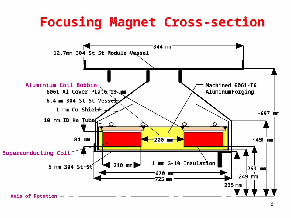
210 mm
84 mm
670 mm725 mm
235 mm
249 mm
263 mm
~450 mm
Machined 6061-T6 Aluminum Forging6061 Al Cover Plate 13 mm
6.4 mm 304 St St Vessel
1 mm Cu Shield
10 mm ID He Tube
5 mm 304 St St 1 mm G-10 Insulation
~697 mm
844 mm
200 mm
12.7 mm 304 St St Module Vessel
Focusing Magnet Cross-section
Axis of Rotation
Superconducting Coil
Aluminium Coil Bobbin

4
Schematic of the Focusing Magnet Cold Mass Support
Support Band
50 K Intercept
Coil Support Bracket
Cold Mass
Vacuum Vessel
Support Adjustment
The design longitudinal force Wz is 20 metric tons.The design radial force Wr is greater than 5 metric tons.

5
MICE Focusing Magnet Design Parameters
Focusing Coils
470
1414 720 263 210 84 200 76 127
208.3 ~138 ~3.0
Cryostat ID (mm) Cryostat OD (mm) Cryostat Length (mm) Inner Coil Radius (mm) Coil Length (mm) Coil Thickness (mm) Coil Spacing (mm) Number of Layers Number of Turns per Layer Current @ 200 MeV/c (A) Self Inductance (H) Stored Energy (MJ)
Coupling Coils
1394
>2160 386 725 250
116.6 -NA- 104 151
175.7 ~580 ~8.0
*
*
* This applies for p = 200 MeV/c and = 420 mm
Module L = 844 mm
Coils operate inGradient mode
6061-T6 Al

6
Support Structure Deflection and Stress of the Focusing Magnet at Maximum Current
Force Model Displacement Stress
max = 80.86 MPamax = 0.227 mm
Fr = 8.87 MNFz = 3.52 MN
p = 240 MeV/c, = 420 mmCoil Current = 250.0 A

7
The Focus Coil Load Lineand its Temperature Margin
10864200
100
200
300
400T = 3.4 K
T = 4.2 K
T = 5.0 K
Focusing
Magnetic Induction at Conductor (T)
Con
du
ctor
Cu
rren
t (A
)
200 MeV/c
240 MeV/c
0.955 mm
1.60 mm
Formvar Insulation
1.65 mm
1.00 mm
Cu to S/C Ratio = 4Cu RRR > 100No. Filaments = 55Filament Diameter = 78 mJc(4.2 K, 5 T) = 2940 A mm-2
Ic (4.2 K, 5 T) = 760 ATwist Pitch = 12.7 mm
Conductor Parameters
I = 208.3 A
I = 250.0 A

8
Focus Coil Heat Load 1st Stage = 52 W (42 to 44 W is the leads)Focus Coil Heat Load 2nd Stage = 1.2 to 1.9 W (depending on 1st stage T)
Cooling the Focus Coil with aSumitomo 1.5 W @ 4.2 K Cooler
Note: There is at least one other cooler that is suitable for cooling the focus Magnet.

First Stage of Cooler 1 cooler 2 coolers MLI Radiation Heat Leak (W) 4.8 4.8
Cold Mass Support Heat Leak (W) 3.0 3.0
Plumbing Heat Leak (W) 1.0 1.0
Current & Instrumentation Lead Heat Load (W) 42.6 42.6
Total Heat Load to 1st Stage per Cooler (W) 51.4 51.4
First Stage Temperature (K) ~63 ~40
Second Stage of Cooler 1 cooler 2 coolers
MLI Radiation Heat Leak (W) 0.45 0.36
Cold Mass Support Heat Leak (W) 0.15 0.07
Plumbing Heat Leak (W) 0.25 0.12
Current & Instrumentation Lead Heat Load (W) ~1.0 ~0.6
Total Heat Load to 2nd Stage (W) ~1.85 ~1.15
2nd Stage Temperature (K) > 4.6 > 3.4
Why use two coolers instead of one?
Answer: To lower the 1st and 2nd stage temperatures and lower the heat leak to the 2nd stage.

10
How the magnet is cooled affectsthe T in the magnet cold mass.
a) Magnet cooled in one area b) Magnet cooled around the outside
T = 4.30 KT = 4.30 K
T = 5.40 K
T = 4.43 K
QR = 1.0 W m-2
QR = 1.0 W m-2
Cooling all around the outside of the cold mass reduces the T within the cold mass by a factor of eight over line cooling in a region 100 mm wide over the length of the cold mass.
Cooled Region100 mm Wide

11
Cryogen free cooling of the MICE focus magnet is possible.
T1
T0
Cooler 2nd Stage Cold Head
Flexible Copper StrapT3
Vacuum Vessel
Focusing Magnet
T2
T = T3 - T0. However T is dominated by T2 - T1, the strap T.
L > 350 mm

12
What is wrong with cryogen free cooling for the focus coil?
• The cooler must be attached to the magnet through a flexible copper strap. The T from the magnet to the cooler cold head is proportional to the strap length and is inversely proportional to the strap cross-section area and thermal conductivity.
• The minimum strap length for the focus magnet is about 350 mm. For a T less than 0.2 K, the strap area must be from 25 to 50 cm2 depending on the RRR of the strap copper.
• There is the added T within the magnet from the strap to the magnet high field point
Advantage: A cryogen free coil can be cooled down with the coolers.

13
Magnet connection to the Cooler with a Liquid Helium Cold Pipe
P
T3
T2
T1
T0
Cooler 2nd Stage Cold Head
Condensation Plate
Vacuum Vessel
Liquid Tube (any length)
Gas Tube (any length)
Liquid Helium
Focusing Magnet
Relief Valve
Cryostat Neck
T = T3 - T0 is small. T3 - T2 may be the largest single term.
14
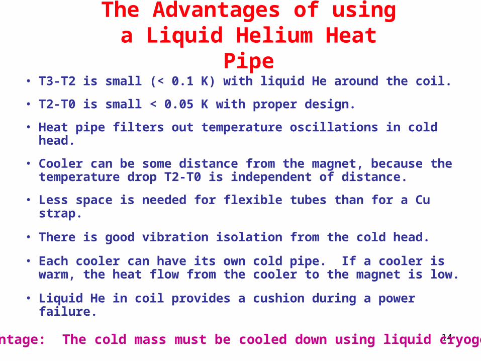
The Advantages of using a Liquid Helium Heat Pipe
• T3-T2 is small (< 0.1 K) with liquid He around the coil.
• T2-T0 is small < 0.05 K with proper design.
• Heat pipe filters out temperature oscillations in cold head.
• Cooler can be some distance from the magnet, because the temperature drop T2-T0 is independent of distance.
• Less space is needed for flexible tubes than for a Cu strap.
• There is good vibration isolation from the cold head.
• Each cooler can have its own cold pipe. If a cooler is warm, the heat flow from the cooler to the magnet is low.
• Liquid He in coil provides a cushion during a power failure.Disadvantage: The cold mass must be cooled down using liquid cryogens.

15
Concluding Comments
• The focus coils are designed to carry internal forces up to 360 metric tons.
• The cold mass supports are designed for 20 tons in the z direction and >5 tons in the r direction.
• The magnet can is cooled with a pair of coolers.
• The magnet cold mass should be cooled down with liquid cryogens.
• The T from hot spot to cooler cold head <0.2 K.