1. The motor effect THE MOTOR EFFECT A current carrying wire will experience a force in the presence...
51
-
Upload
alban-hicks -
Category
Documents
-
view
218 -
download
1
Transcript of 1. The motor effect THE MOTOR EFFECT A current carrying wire will experience a force in the presence...


1. The motor effect1. The motor effect

THE MOTOR EFFECT
A current carrying wire will experience a force in the presence of a magnetic field.
When the switch is closed a current will flow in the aluminium rod. It will suffer a force due to the effect of the magnetic field and the rod will move (you can use this as an experiment)
If either the poles of the magnet or the poles of the DC source are changed around the direction of movement will change.
The direction of movement (i.e. of the force) can be found using the right-hand-slap rule.

Magnitude of the forceThe magnitude of the force is given by the formula: F = B I L sinWhere,
F = force(N); B = Magnetic field strength (T); I = current(A); L = length of conductor in external magnetic field (m); and angle of conductor to magnetic field
It follows that:
*As the strength of the magnetic field in which the conductor is located increases, the force increases
*As the magnitude of the current in the conductor increases, the force increases
*As the length of the conductor in the external magnetic field increases, the force increases
* As the angle between the direction of the external magnetic field and the direction of the length of the conductor approaches force is max, when(i.e. parallel to magnetic field lines)force =

TorqueThe product of the force applied to a lever and its distance from the lever's fulcrum is defined as the torque
= Fd
Where, = torque (Nm) ; F = force (N) perpendicular to the axis of rotation and d (m) = distance from the fulcrum to the force.
In the rectangular coil shown, because there are two forces acting, the torque on the coil is:
= 2(F x 1/2a) = Fa
If the coil is a conductor and is placed in a magnetic field, B (T) and a current I (A) flows through the coil, then
F = BIL
Therefore torque will be = BILa,
But L x a =Area (m2) of coil,
therefore = BIA
For angles other than = 0= BIA cos
If the coil has 'n' turns then = nBIA cos

The two forces will cause the coil to rotate in a clockwise direction
As the coil rotates the forces remain the same but the torque on the coil changes
When the coil is in position 1 torque is maximum
In position 2 the torque will depend on the angle = nBIA cosWhen coil is in position 3 the torque is zero and the tendency to rotate will stop.
If the momentum of the coil carries it over the vertical position the forces will reverse and return it to the vertical position
To continue rotating clockwise the direction of the current must be reversed
Rotation

DC motorIf a commutator is fitted to the coil as shown, the current reverses every half cycle and the coil will rotate continuously: this arrangement is known as a DC motor.
The commutator is in contact with “brushes” which carry the current to the coil.
In practical motors the coil has many turns (to increase torque) and there are more than one coil angled at regular intervals (to avoid the momentary slow down when a single coil is vertical)
The faces of the magnet are not flat but curved so that the magnetic field is parallel to the plane of the coil throughout the rotation.
The magnet can be a permanent magnet or an electromagnet with its coil forming part of the circuit.
The brushes are usually made of graphite as it is a good conductor and is self lubricating
Some degree of sparking occurs at each gap in the commutator, therefore these motors are not safe in areas where inflammable solvents are used.
The coils are called the rotor or armature and the stationary magnet the stator.

Parallel wiresParallel, current-carrying wires experience forces between them because their respective magnetic fields interact.
When the currents in both wires are in the same direction the magnetic fields between them are going in opposite direction and they diminish each other and the two wires are pulled together (attraction)
When the currents in both wires are in the opposite direction the magnetic fields between them are going in same direction and they strengthen each other and the two wires are pushed apart (repulsion)
In each case the force (F) experienced by each wire is identical in magnitude and depends on the magnitude of the currents in each (I
1 and
I2), on the distance between them (d) and on
their length (L):
k in the equation is a constant which has the value 2 x 10⁻⁷ T m A-1.

Some Calculations
Answering Physics calculation-type questions:
Draw a quick, but accurate sketch of the problem
Enter all the data given, make sure you change each to standard units
Choose from the formula-list supplied and write down the formula that applies to the problem
If necessary, change the subject of the formula to obtain the answer requested (following algebraic rules)
Substitute correctly in the formula
Calculate your result and give the answer to the same significance level as was used in the question
If more than one calculation is necessary , do not round-off any numbers until the end
I. A 1 m long conductor, carrying a current of 0.5 A, is placed in a magnetic field of 0.003T at an angle of 30o to the magnetic field. If only 23 cm are in the magnetic field. Calculate the force on the wire.
II. A rectangular loop of wire consisting of 35 turns and having sided 2 cm x 4 cm is placed between the poles of a magnet at an angle of 45o to their magnetic field of 0.0007 T . If the current in the loop is 1.6 A, calculate the torque on the loop.
III. Three parallel wires are 15 cm apart. Each carries a current of 2A, the middle wire has the current going in the opposite direction to the other two. Calculate the force per unit length on the outer wires. Estimate the force on the middle wire.

It is very important that you right down the correct formula and then do the correct substitution of values.
The actual answer, although important, is secondary to those two crucial steps.
Generally, full marks will be awarded for the correct substitution in the correct formula.

The galvanometer
A galvanometer uses the motor effect to measure the magnitude of an electric current.
The current flows through a coil wound around a soft iron core, suspended in the field of a permanent magnet.
The resulting motor effect produces a torque on the coil which is opposed by a circular spring. When the restoring force in the spring exactly balances the electrically induced torque the pointer stops and the current is read from a previously calibrated scale.
The pole faces of the magnet are curved to ensure that the magnetic field is even and so produces a torque of approximately constant value within the range of the needle swing.
The torque on the coil is directly proportional to the current as the coil rotates, allowing an evenly divided scale to be used.

The Loudspeaker
The electric current flowing through the coil varies with respect to the signal generated by the equipment attached to the speaker wires (radio, telephone, amplifier etc).
The motor effect sets the coil vibrating 'in concert' with the changes in the current supplied by the signal acting in the strong magnetic field from the permanent magnet.
The vibrating cone amplifies the vibration of the coil producing sound waves as the air is set vibrating.

Revision questions - 1
1) Discuss the effect on the magnitude of the force on a current-carrying conductor of variations in: the strength of the magnetic field in which it is located; the magnitude of the current in the conductor; the length of the conductor in the external magnetic field; the angle between the direction of the external magnetic field and the direction of the length of the conductor
2) Describe a first-hand investigation you performed to demonstrate the motor effect
3) Describe the application of the motor effect in: the galvanometer and the loudspeaker
4) Describe qualitatively and quantitatively the force between long parallel current-carrying conductors.
5) Define torque.
6) Define the motor effect.
7) Describe the forces experienced by a current-carrying loop in a magnetic field .
8) Describe, using a sketch and labeling, the main features of a DC electric motor and the role of each feature
9) Identify how the required magnetic fields in DC motors can be produced.


Faraday's lawIn 1831 English chemist and physicist Michael Faraday (1791-1867) believed that if an electric current could cause a magnetic field (as had been shown by Oersted and Ampere) then, a magnetic field should be able to produce an electric current.
After many experiments, Faraday found that only a moving or changing magnetic field would induce a current in a conductor
At first, he induced an electric current in a rotating disc of copper metal between the poles of a strong magnet, essentially he had invented the first generator. Later, he induced currents using coils wound on the same soft iron ring and not only deduced his Law of electric induction, but also invented the first transformer.
His law states:
“The induced electromotive force or emf () in a closed circuit is given by the time rate of change of the magnetic flux () through the circuit.”
Note: the minus charge is related to Lenz's law

Magnetic Flux Faraday described magnetic flux as the total number of magnetic flux lines that pass through a given area (he was the first to introduce the concept of lines to represent electric and magnetic fields).
The magnetic flux through a surface is proportional to the net number of magnetic field lines that pass through the surface.
Magnetic flux is given by:
= BA
The units for magnetic flux are the Weber (Wb)
It follows that:
= / A• The magnetic field strength (B) is thus
defined as the magnetic flux density and 1T = 1 Wb m-2

Lenz's LawHeinrich Lenz was a Russian physicist who in 1833 formulated a law concerning electromagnetic induction. It is now known as Lenz's law:
“The induced electric current flows in a direction such that the magnetic fields
generated by the current will oppose the change that induced the current”
A small amount of work is done in pushing the magnet into the coil and in pulling it out against the magnetic field formed by the induced current.
Lenz's law is a consequence of the Law of Conservation of Energy.
If the current were induced in the opposite direction, its action would spontaneously draw the bar magnet into the coil, thus increasing the induced emf which, in turn would increase the strength of the induced field, further accelerating the magnet, and so on.
Energy would be created, contravening the Law of Conservation of Energy.

The set-up shown is one that will answer the requirements of the syllabus first-hand investigation. If a CRO is not available it maybe substituted with a sensitive galvanometer or a data logger.
The coil is connected to a CRO which will give a read-out of the emf induced when the magnet is in motion.
The movement of the magnet should be kept fairly constant for the first parts of the experiment.
I. The distance between the coil and magnet is varied by lowering and raising the magnet
II. The strength of the magnet is varied by using stronger magnets (e.g. neodymium magnets)
III. The relative motion between the coil and the magnet is varied by oscillating the magnet faster.
Generating a current

Eddy currents The French physicist Léon Foucault in 1851 discovered eddy currents (or Foucault currents) when he exposed a conductor to a changing magnetic field.
The currents formed are similar to the circulating eddies in a river, hence their name. They create induced magnetic fields that follow Lenz's law and oppose the change caused by the original magnetic field.
Like all electric currents, eddy currents generate heat depending on the resistance of the material. The heat may be harnessed in a form of heating called induction heating.
The opposing magnetic fields induced by eddy currents can be used for a form of braking called induction braking.
Eddy currents are increased by: stronger magnetic fields; faster changing fields; thicker materials and lower resistivity materials (aluminium, copper, silver etc.).
Eddy currents are decreased by the opposites to the conditions mentioned above, as well as: slotted materials and laminated materials so that currents cannot circulate freely.

Induction braking
An eddy current brake or induction brake, like a conventional friction brake slows a moving object. (e.g. train, fly wheel or roller coaster). Induction brakes slow an object by creating eddy currents which oppose the movement.
Induction braking is virtually fail-safe because it relies on the basic properties of magnetism and requires no electricity. Magnetic brakes are also completely silent and are much smoother than friction brakes.
In roller-coasters, magnetic brakes are made up of one or two rows of very strong Neodymium magnets. When a metal fin (typically copper or a copper/aluminum alloy) is raised between the rows of magnets, eddy currents are generated in the fin, which creates a magnetic field opposing the roller-coaster's motion.
The resultant braking force is directly proportional to the relative speed between the magnets and the metal fin.
This property is also one of the disadvantages of induction braking: in that the eddy force itself cannot completely stop a train, it can only slow it down.

Induction heatingInduction heating is the process of heating a metal object by electromagnetic induction. Eddy currents are generated within the metal and its resistance leads to heating of the metal.
An induction heater (for any process) consists of an electromagnet, through which a high-frequency alternating current (AC) is passed. The frequency of AC used depends on the object size and type of material.
In induction cooking, an induction coil in the cook top heats the metal base of the pot by inducing alternating eddy currents of high frequencies. Glass or ceramic pots cannot be heated in this way as they are non-conducting. The heat induced in the base is transferred to the food via conduction and convection.
Cookware must generally be made of ferrous materials. Copper or aluminum pans will not work on a typical induction cooker as their resistance is too low. Newer cook tops are being developed that are designed to work with any metal, including copper and aluminum,
Benefits of induction cookers include efficiency, safety (the cook-top remains cool to the touch) and speed.
According to the Electric Glass Company, a producer of induction cook tops, "power savings of 40-70% are realistically achievable in comparison to conventional cook tops."
Other uses of induction heating are: Induction furnaces and Induction welding.

Back emfAs the rotor of an electric motor rotates in the stator's magnetic field an electric current is induced in its coils (Faraday's Law). This induced current will flow in the opposite direction to the current applied externally (Lenz's law)
This current will produce an emf in the coils that is opposite in direction to the applied emf and hence is known as back-emf.
The net emf driving the motor is the difference between the applied emf and the back emf. The electrical resistance of the motor will determine the current through the coils.
net
= applied
- back
and net
= RI
As the motor increases in speed the back emf also increases in value but, the applied emf remains constant, (as long as it isn't changed externally).
• At the point where the two emf's are 'balanced' the motor reaches constant speed for that supplied voltage (emf). The net emf and current flowing are just enough to overcome the frictional and load forces.
Example problem:
(i) Calculate the internal resistance of a motor if it draws 1.5 A on start-up when connected to 240 V.
(ii) Once the motor reaches full speed it draws only 0.05 A at constant speed. Calculate the back emf at this point.
Answer:
(i) R = V / I
= 240 / 1.5
= 160
ii) net
= applied
- back
0.05 x 160 = 240 - back
back
= 240 - 80
= 160 V

Back emf and motorsWhen more load is applied to the motor, the coils slow down and the back emf is reduced. A greater current will now flow through the coils. It will result in an increased torque to handle the increased load.
However, if the load is too great, too much current will flow through the coils. Their temperature will increase and eventually they will melt - the motor will have “burned out”
Larger DC motors, to be efficient, need a lot of windings with a minimum of mass. Hence, thin wire is used in their armatures. These thin wires run the chance of burning-out at the low start-up speeds (when the back emf is low).
For this reason, motor coils are usually protected by a series resistors. These 'switch-off' at higher speeds when the back emf reduces the net current .

Revision questions - 2
1) Outline Michael Faraday's discovery of the generation of an electric current by a moving magnet
2) Describe how magnetic field strength B can be defined as magnetic flux density
3) Describe the concept of magnetic flux in terms of magnetic flux density and surface area
4) Describe the generated potential difference as the rate of change of magnetic flux through a circuit
5) Account for Lenz's Law in terms of conservation of energy and relate it to the production of back emf in motors
6) Explain back emf in electric motors.
7) Explain using appropriate sketches the production of eddy currents in terms of Lenz's Law
8) Describe an investigation you performed to model the generation of an electric current by moving a magnet and a coil.
9) Describe a first-hand investigation you performed to verify the effect on a generated electric current when: the distance between the coil and magnet is varied; the strength of the magnet is varied and he relative motion between the coil and the magnet is varied
10) Explain how induction is used in cook tops in electric ranges
11) Explain how eddy currents are used in electromagnetic braking

The DC generator or dynamoA generator converts mechanical energy to electric energy by spinning a coil of wire in a magnetic field - electromagnetic induction.
In a DC generator a commutator and brushes carry the generated electric current to where it is needed e.g. a light bulb
In practice, the rotor is made up of many windings around a laminated soft iron core on a rotating axle and the assembly is known as the armature
The magnets are rounded for optimum induction (they hug the rotation of the armature). They can either be permanent or electromagnets and are known as field magnets.
The brushes are graphite and pick up the current from the coil through a commutator
Essentially it is identical to a DC motor except that electric power is generated. It is not used-up as in a motor i.e. motors convert electric energy to mechanical/rotational energy. Generators convert rotational/mechanical energy into electrical energy

Generating an AC current
The same equipment that was used on a previous occasion can be set up.
As the permanent magnet oscillates in and out of the coil an AC current is produced that can be detected by the CRO.
Varying the period of oscillations will produce AC currents of different frequencies (The AC current from a normal domestic power point has a frequency of 50Hz)
Other variables that can be investigated are: the strength of the magnet ; the speed of the magnet; the relative position of the magnet to the coil
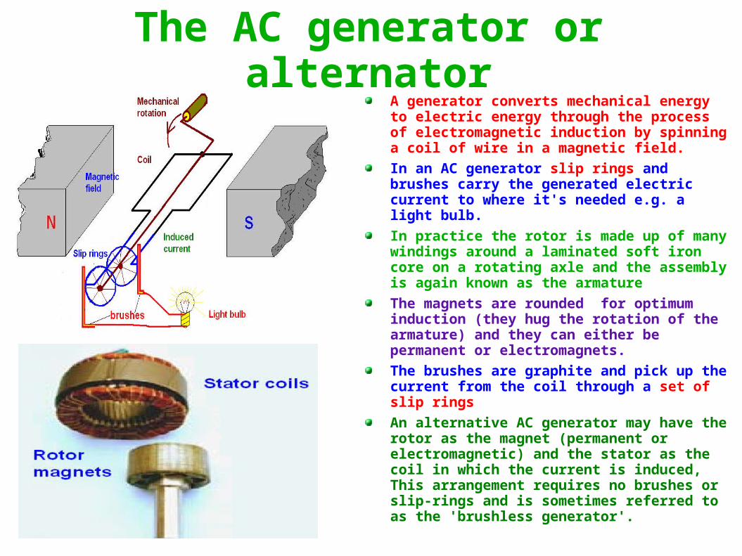
The AC generator or alternatorA generator converts mechanical energy to electric energy through the process of electromagnetic induction by spinning a coil of wire in a magnetic field.
In an AC generator slip rings and brushes carry the generated electric current to where it's needed e.g. a light bulb.
In practice the rotor is made up of many windings around a laminated soft iron core on a rotating axle and the assembly is again known as the armature
The magnets are rounded for optimum induction (they hug the rotation of the armature) and they can either be permanent or electromagnets.
The brushes are graphite and pick up the current from the coil through a set of slip rings
An alternative AC generator may have the rotor as the magnet (permanent or electromagnetic) and the stator as the coil in which the current is induced, This arrangement requires no brushes or slip-rings and is sometimes referred to as the 'brushless generator'.

DC and AC generatorsThe only real difference between AC and DC generators is in the type of connection used to source the induced current from the coils in the rotor (slip or split rings).
This difference results in a very different type of current signal being produced by each as is shown here.
In a single coil DC generator the current is induced in the coil for a half a turn. The maximum voltage is reached when the coil is completely parallel to the magnetic field.
When the split in the commutator touches the brushes no current flows or is generated, hence the voltage available drops to zero to start again as the commutator moves on. The result is a current flowing in one direction only.
In a single coil AC generator, with the brushes running on slip rings a constant connection is maintained with the external circuit. This means that the polarity changes every half-turn and a current that changes direction is produced.

AC and DC generatorsDC
DC generators use a split-ring commutator.
In DC generators the output current is always induced in the rotor.
Brushes and commutators wear out quickly and short circuits in the commutator are possible due to sparking. Arcing is likely after prolonged use.
DC generators will require regular maintenance.
In a DC generator the current is generated in the rotor. If larger the currents are required, heavier rotor coils must be used. This will increase maintenance problems.
A DC generator can be made using many coils in a regular pattern around the armature resulting in a smooth output with just a small 'ripple'. This is an advantage with equipment that needs a steady voltage rather than a fluctuating one.
ACAC generators use slip-rings.
in an AC generator the output current can be induced in the rotor or the stator.
In an AC generator the slip-rings have continuous, smooth surfaces, allowing the brushes to remain continuously in contact with the slip ring surface. Thus the brushes in an AC generator do not wear as fast as in a DC generator and there is little or no possibility of creating an electrical short circuit.
An AC generator will requires less maintenance and will be more reliable than a DC generator.
In an AC generator the rotor can be used to create the magnetic field that induces AC current in the stator (as the rotor rotates). The current will be drawn using a fixed connection to the stator which is much more reliable than through a moving commutator.
An advantage of AC generators is that they can easily be designed to produce three-phase electricity. This makes them ideal for generating electricity on a large scale for distribution over a wide area.

Edison and Westinghouse(the "War of Currents" 1880s)
Edison
Edison aggressively promoted generating and supplying direct current (DC)
Edison carried out a campaign to discourage the use of alternating current, including spreading information on fatal AC accidents and publicly killing animals including a circus elephant
Edison opposed capital punishment, but his desire to disparage the system of alternating current led to the invention of the electric chair to promote the idea that AC was deadlier than DC.
When the chair was first used, on August 6, 1890, the technicians on hand misjudged the voltage needed to kill the condemned prisoner, William Kemmler and the procedure had to be repeated a number of times.
Westinghouse commented:
"They would have done better using an axe."
Westinghouse
Westinghouse and Nikola Tesla advocated the use of alternating current (AC) electricity.
Westinghouse, using Tesla's AC system, won the international Niagara Falls Commission contract. On November 16, 1896, electrical power was sent from Niagara Falls to industries in Buffalo.
AC replaced DC for central station power generation and power distribution, enormously extending the range and improving the safety and efficiency of power distribution.
The Chicago World's Fair in 1893 exhibited a complete poly-phase generation and distribution system installed by Westinghouse and invented by Tesla.
The successful Niagara Falls system was the turning point in the “War of Currents” and the acceptance of AC.
The final irony is that Tesla had worked for Edison but Edison had discounted his AC system saying:
“Tesla's ideas are splendid, but they are utterly impractical”

Why is AC better for power transmission than DC?
DC
DC cannot be stepped up or down in voltage easily (especially in the 1880s) hence it had to be distributed at the voltages used by the consumer
Since the resistance of the wire is pretty much constant low voltages meant high currents. High currents resulted in large power losses over relatively short distances ( less than 2 km)
This meant that a lot of power or boost stations were needed to supply large cities and from locations where hydroelectric power could be generated.
• Today, through the use of solid state electronics it has become easy to switch from DC to AC and if high temperature superconductors are developed, transmission of power as DC may prove to be more economical.
AC• AC can easily be stepped up and down in
voltage using transformers• AC could be generated at a low voltage,
stepped up to very high voltages for transmission and then stepped down again for consumer use.
• Higher voltages-low currents are better for power transmission because the power lost in transmission due to the wire resistance is proportional to the square of the current (P=I2R) but only directly proportional to the voltage (P =VI)
• With AC the power loss per kilometer was a lot lower hence power or boost stations could be spaced far apart, resulting in a much cheaper and more attractive grid system
• AC had the disadvantages that it caused power loses through electromagnetic radiation and induction and the frequencies used were apt to be more deadly.

Power losses
• Power is lost during transmission because of the natural resistance of the wire and because of electromagnetic induction of eddy currents.
• The losses occurring because of electrical resistance result in heating of the wire and loss of energy to the environment, they can be minimized by using:– Very high voltage AC and low currents– Good conductors like copper or aluminium– Lines with large cross-sectional area (this must
be off-set by the weight of the line hence aluminium is often preferred as it has a lower density)
• Losses due to the induction of eddy currents can be minimized by:– Supporting the wires away from metal towers– Using laminated iron cores in transformers used
to step up and step down the voltage– Eddy currents result in overheating of
transformers. Cooling transformers with circulating oils and radiative fins reduces over heating. This also further energy losses due the increase in resistance which comes with increasing temperature.
Sample calculation of power-loss
Compare the energy losses in the transmission of 1 MW of power over a line with a resistance of 1.5 ohm per kilometer between using high voltages/low currents and low voltages/high currents.
P=VI
1, 000,000 = 200,000 x 5 (HV/LA)
or = 5000 x 200 (LV/HA)
Power lost / km in the 1st case is:
P = I2R = 52 x 1.5 = 37.5 W
Power lost / km in the 2nd case is:
P =I2R = 2002 x 1.5 = 60 000 W

Power transmission insulators
• Insulators used for high-voltage power transmission are made from very high resistance materials like glass, porcelain, or composite polymer materials and are covered with a smooth glaze to shed dirt and water. This keeps surface conductivity to a minimum.
• High voltage insulators are shaped into a series downward facing, cup-shaped surfaces that act as umbrellas. This not only maximizes the length of the leakage path along the surface from one end to the other but also avoids over-wetting in rainy weather.
• Even higher voltage transmission lines use modular cap and pin insulator designs . The wires are suspended from a 'string' of identical disk-shaped insulators which attach to each other with metal links. The advantage of this design is that series of insulator disks can be easily assembled to handle different wire voltages.

Protection from lightning• Power lines, being high metal structures, are natural attractors of
lightning strikes. These can cause severe damage to the lines, the towers and to the distribution network , due to high surges in current.
• To protect against the effects of lightning strikes, power lines are often equipped with arresters or with overhead ground wires called shield wires that are well grounded (with large areas of metal buried underground)
• An arrester behaves like an open circuit when the line is in normal operation. When the line is hit by lightning, the arrester acts more like a fuse by diverting the lightning current to the ground and holding the voltage at safe value.
• The shield wires are placed above the lines and are designed to be 'hit' before the lines by the lightning.
• Shield wires are connected directly to the transmission towers without the use of insulators, when they are struck by the lightning, the current is conducted safely to earth.
• Some very tall transmission lines may have two sets of shield wires.

“The effects of AC generators on society and the environment” 1
Any paradigm changing invention or technology is bound to have good and bad effects on the way society develops. It will have its admirers and its detractors. There is little doubt that the generation of freely available AC power has had a major influence on how society is structured today.
On the whole, its effect has to be recognised as having been beneficial. It has allowed for the ability to feed, clothe, keep warm in winter and cool in summer, transport, entertain and care for a large number of people.
Without full scale power transmission it is doubtful whether we would have factories to make all affordable, labour saving and life saving goods we take for granted every day. The humble refrigerator, for example, has probably saved a countless number of people from sore tummies and even from deadly food poisonings.
Hospitals would be unmanageable without electrical equipment for monitoring and carrying out surgical procedures, storing of pharmaceutical and important biological samples.
The world would be a very different place without AC power. Life would be a lot harder for the great majority of people. Death and sickness rates would be a lot greater.
With no electricity, the burning of high pollution fuels could be widespread - at the start of the industrial revolution coal burning caused terrible smog in places like London and many people died during long, cold winter nights.
(cont.)

“The effects of AC generators on society and the environment” 2
The relative cheapness of electricity has promoted the development of a wide range of machines, processes and appliances that depends on electricity. Many tasks that were once performed by hand are now accomplished with electrical appliances and most domestic and industrial work requires less labour. Other new tasks can now be achieved that were formerly impossible, such as electronic communication.
Some believe that this has caused widespread unemployment. Unemployment was not any better before electricity - with no large factories, no electrical goods and automotive production, little or no entertainment industry. Before cheap electricity, poverty was widespread and child-labour a common practice.
Air pollution from fossil-fuel burning power stations has contributed to acid rain and contributed to the global warming. At the time that Power generation was introduced, there was no technology to harness solar energy or wind energy or anything else but: wood, coal and gas. Global warming might be even worse by now without AC generators.
AC electricity has helped us with all the technological advancement that have occurred, now we have the ability, the know-how to and the need look for alternatives.

Revision questions - 3
1) Describe using sketches and labeling the main components of a generator
2) Compare the structure and function of a generator to an electric motor
3) Describe the differences between AC and DC generators
4) Discuss the energy losses that occur as energy is fed through transmission lines from the generator to the consumer
5) Assess the effects of the development of AC generators on society and the environment
6) Describe a first-hand investigation you performed to demonstrate the production of an alternating current
7) Discuss advantages/ disadvantages of AC and DC generators and relate these to their use
8) Describe the competition between Westinghouse and Edison to supply electricity to cities
9) Explain why transmission lines are: i) insulated from supporting structures and ii) protected from lightning strikes


Transformers • Electrical transformers are used to change AC voltage from one value to another. They do this through magnetic induction.
• Magnetic induction demands a changing magnetic field, hence transformers only work with AC current.
• Transformers can either be classed as step-up or step-down
• Step-up transformers have:– More turns in the secondary coil than
the primary coil– Higher output voltage than input
voltage – Lower output current than input
current• Step-down transformers have:
– More turns in the primary coil than the secondary coil
– Lower output voltage than input voltage
– Higher output current than input current

Voltage transformations• The relationship between the number of turns in each coil
and the voltage transformation is given by:
Vp / V
s = n
p / n
s
• In the ideal transformer, according to the Law of Conservation of Energy, energy-in must equal energy-out , hence power-in must equal power-out :
Pp = P
s
• Hence in the ideal transformer:
Ip / I
s = n
s / n
p
• In reality, transformers show power/energy losses in the transformation of voltage. This is because heat is produced by the induced eddy currents in the iron core due to its significant electrical resistance. The power output is always lower than the power input.
• The formation of eddy currents (and hence their heating effect) can be reduced by using laminated iron cores (many thin lamina or sheets of iron pressed together and separated by thin insulating layers of oil, lacquer or wax. This restricts the formation of eddy currents to the thickness of one lamina).
• Once hot, transformers need to be cooled. Large transformers are oil cooled and have cooling fins and are located outside where air circulation helps to dissipate the heat produced.
Sample calculation:
A transformer manufacturer has to construct a transformer to output 9V when connected to domestic power supply of 240V. If their standard primary coil has 1000 turns, find how many turns they will need in the secondary coil. They know that the current flowing through the primary coil will be 0.05 A, transformer what will be the maximum current possible in the secondary coil?
vp/v
s=n
p/n
s
240/9=100/ns
ns=38
Maximum current will be if transformer is ideal
Ip/I
s=n
s/n
p
0.05/Is=38/1000
Is=1.32 A
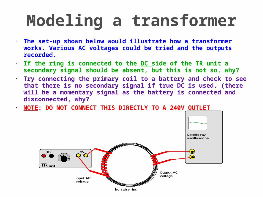
Modeling a transformer• The set-up shown below would illustrate how a transformer works.
Various AC voltages could be tried and the outputs recorded.• If the ring is connected to the DC side of the TR unit a secondary signal
should be absent, but this is not so, why?• Try connecting the primary coil to a battery and check to see that there
is no secondary signal if true DC is used. (there will be a momentary signal as the battery is connected and disconnected, why?
• NOTE: DO NOT CONNECT THIS DIRECTLY TO A 240V OUTLET

Transformers in sub-stations
• Power stations generate electricity at voltages between 2000 volts and 30,000 volts, depending on their size. To minimise energy loss due to resistance in transmission wires the voltage is stepped-up by the power station to 115kV to 765 kV (typically about 500kV) for transmission over long distances.
• Electricity distribution is accomplished with a combination of sub-stations and pole mounted transformers that reduce the voltage to a lower level for distribution to commercial and residential users.
• At each stage, the output voltage is chosen to match the power demand and the distances over which supply is needed. Finally, it is transformed to low voltages of 240V single phase or 415 V over three phases to operate most industrial and domestic equipment and appliances
• Electric power transmission to rural and remote areas, in contrast to urban systems, tend to use higher voltages because of the longer distances covered by those distribution lines.

Transformers in the home• Many appliances like washing machines and fridges are
designed to run on a supply of 240V and do not need further use of transformers. If they have computer controlled circuits and digital displays that run at much lower voltages like 1 to 9 V, then step-down transformers are needed
• The older style television and computer tubes were based on cathode ray tubes which required high voltages, hence these appliances incorporated step-up transformer units that produced highly dangerous voltages of 20,000 V or more.
• Many commonly used electronic equipment like mobile phones require a recharge transformer coupled to an AC-DC rectifier to be able to run or re-charge
• Leaving transformers (e.g. mobile re-chargers) connected to the power point, when not in use, is dangerous and wasteful. The transformer continues to operate for as long power flows through it.

The impact of transformers on society
• Transformers have made possible the economic transmission of electrical power, hence most of the discussion points that were used for the effect of generators on society can be adapted to this discussion, as both relate to the proliferation of AC electricity throughout our society.
• The ready access to an economical power supply has had a great influence on the growth of cities into suburbs (e.g the continuous spreading of Sydney in a westerly direction) and the growth of non- urban localities in far-away rural locations.
• Relatively cheap power has seen the explosion in temperature control (both heating and cooling) of our living environment. It has been especially useful in the our the storage of food and medical supplies.
• Easy availability of electrical power has lead to a increasingly de-centralised society, feeing a lot of space previously occupied by factories for human habitation and entertainment.(e.g. Sydney's mid west suburbs and inner city areas)
• Many of the labour saving devices, leisure and entertainment equipment, scientific and life-saving medical apparatus would not have been possible without an economic power supply provided by the use of step-up and step-down transformers.
• Our society has relied and is relying on the availability of power to every home, every factory, every office to such an extent that most of us cannot conceive a world without it.
A very good depiction of what might happen to a society like ours if all power were suddenly to be switched off can be found in the semi-fictional novel “One second after” by William R Forstchen ). It is an exciting read, especially because its premise is based on scientific fact.

Revision questions -41) Describe the purpose and principles of transformers in electrical
circuits
2) Compare step-up and step-down transformers
3) Identify the relationship between the ratio of the number of turns in the primary and secondary coils and the ratio of primary to secondary voltage
4) Explain why voltage transformations are related to conservation of energy
5) Explain the role of transformers in electricity sub-stations
6) Discuss the use of transformers in the home.
7) Discuss the impact of the development of transformers on society
8) Describe investigation you performed to model the structure of a transformer to demonstrate how secondary voltage is produced
9) Discuss how difficulties of heating caused by eddy currents in transformers may be overcome
10)Discuss the need for transformers in the transfer of electrical energy from a power station to its point of use


Demonstrating the principle of an AC induction motor
• The set-up should spin easily once it is balanced on the watch glass and small cuts are made in the Balsa to fix it in position
• The embedded tacks are there to keep the neodymium magnets in position (check that the tacks are attracted to the magnets first).
• Once the magnets are spinning on the watch glass gently lower a disc of aluminium foil and note that it starts rotating in the same direction .
• Eddy currents form in the aluminium disc that try to stop the rotation by forming poles of opposite polarity to the magnets, and hence are dragged with it. Notice that it 'lags' behind the rotation of the magnets.
• Check that the aluminium disc is not affected if there are no magnets.
• Once the experiment is over try to make cuts on the disc with a pair of scissors to reduce the circulation of eddy currents and then test your efforts by comparing it to how it behaved before you cut it.

AC motors• There are different types of AC motors which run at
constant speeds depending on the frequency of the AC source (about 3000 rpm for 50Hz):
• The universal motor, which is basically a DC motor run with AC; The synchronous motor which is like an AC generator with slip rings but is run as a motor by connecting it to AC.
• The most common type of AC motor is the induction motor. In 1882, Nikola Tesla invented the rotating magnetic induction motor, where the rotor moves because of a current induced by a rotating magnetic field produced by the stator. It has no brushes or slip rings. The current in the stator maybe single or poly-phase
• The windings in the stator of an induction motor set up a rotating magnetic field around the rotor. The relative motion between this field and the rotation of the rotor induces electric current in the conductive bars.
• These induced currents in the conductor bars react with the magnetic field of the motor to produce force acting at a tangent to the rotor, resulting in torque to turn the shaft.
• The rotor is carried around with the magnetic field with a slightly slower rate of rotation, called slip, which increases with load.
• The iron core spreads the magnetic field evenly across the rotor. The thin laminations, separated by varnish insulation, reduce stray eddy currents.

Some common energy transfers
Type of electrical equipment
transfer of energy from to Typical location
Motor Electrical Mechanical (plus some heat & sound)
Washing machine, record player, DVD
players
Generator Mechanical Electrical (plus some heat & sound) Power stations, car
Transformer Electrical Chemical Battery chargers
Lights, microwave ovens, TV Electrical Electromagnetic
radiation (light etc.)lighting, cooking, X-
ray machines
Loudspeakers Electrical Sound Radio, TV, stereo players
Batteries Chemical Electrical Car, portable Mp3, laptops

Revision questions - 5
1) Describe the main features of an AC electric motor
2) Describe an investigation you performed to demonstrate the principle of an AC induction motor
3) Identify some of the energy transfers and transformations involving the conversion of electrical energy into more useful forms in the home and industry