1. Self- Heat-Trace Panels Regulat- 3. Mineral3. Mineral Insulated Cables 4. Longline Heating 5....
15
H56890 2/11 www.tycothermal.com 1 of 14 1. Self- Regulat- ing Cables 2. Power- Limiting Cables 3. Mineral Insulated Cables 4. Longline Heating 5. Tubing Bundles 6. Tank Heating 7. Snow and Ice 8. Control and Monitoring 9. Heat-Trace Panels 10.Engineered Products 11.Steam- Tracing Systems 12.Technical Data Sheets 13.Appendixes 14.Index This section will help you design and select a dedicated heat-tracing power distribution panel. For design assistance, please contact your Tyco Thermal Controls representative or phone Tyco Thermal Controls at (800) 545-6258. Also, visit our Web site at www.tycothermal.com. Contents Introduction . . . . . . . . . . . . . . . . . . . . . . . . . . . . . . . . . . . . . . . . . . . . . . . . . . . . . . . . . . . . . .1 System Overview . . . . . . . . . . . . . . . . . . . . . . . . . . . . . . . . . . . . . . . . . . . . . . . . . . . . . . . . . .2 Heat-Trace Panels — Group Control . . . . . . . . . . . . . . . . . . . . . . . . . . . . . . . . . . . . . . . . .2 Heat-Trace Panels — Individual Control . . . . . . . . . . . . . . . . . . . . . . . . . . . . . . . . . . . . . .4 Approvals and Certifications . . . . . . . . . . . . . . . . . . . . . . . . . . . . . . . . . . . . . . . . . . . . . . . . . .5 Drawings . . . . . . . . . . . . . . . . . . . . . . . . . . . . . . . . . . . . . . . . . . . . . . . . . . . . . . . . . . . . . . . .5 Panel Design for Three-Phase Systems . . . . . . . . . . . . . . . . . . . . . . . . . . . . . . . . . . . . . . . . .5 Overview . . . . . . . . . . . . . . . . . . . . . . . . . . . . . . . . . . . . . . . . . . . . . . . . . . . . . . . . . . . . . .5 Panel Design . . . . . . . . . . . . . . . . . . . . . . . . . . . . . . . . . . . . . . . . . . . . . . . . . . . . . . . . . . .5 Product Selection . . . . . . . . . . . . . . . . . . . . . . . . . . . . . . . . . . . . . . . . . . . . . . . . . . . . . . . . . .9 HTPG Overview . . . . . . . . . . . . . . . . . . . . . . . . . . . . . . . . . . . . . . . . . . . . . . . . . . . . . . . . .9 HTPG Catalog Number . . . . . . . . . . . . . . . . . . . . . . . . . . . . . . . . . . . . . . . . . . . . . . . . . . .9 HTPG Selection Process . . . . . . . . . . . . . . . . . . . . . . . . . . . . . . . . . . . . . . . . . . . . . . . . .10 HTPI Overview . . . . . . . . . . . . . . . . . . . . . . . . . . . . . . . . . . . . . . . . . . . . . . . . . . . . . . . .11 HTPI Catalog Number . . . . . . . . . . . . . . . . . . . . . . . . . . . . . . . . . . . . . . . . . . . . . . . . . . .11 HTPI Selection Process . . . . . . . . . . . . . . . . . . . . . . . . . . . . . . . . . . . . . . . . . . . . . . . . . .13 Introduction HTPG and HTPI panels are a cost-effective and convenient means of providing ground- fault protection to heat-tracing circuits. Tyco Thermal Controls offers two types of heat-trace panels: the DigiTrace brand HTPG (Heat-Tracing Panel Group Control) and HTPI (Heat-Tracing Panel Individual Control). These distribution panels have the option of using ground-fault circuit breakers (30-mA trip level). Per national electrical codes and Tyco Thermal Controls requirements, ground-fault protec- tion must be provided for each heat-tracing circuit. The HTPG and HTPI panels are a cost- effective and convenient means to provide this protection. Tyco Thermal Controls also supplies specialty panels for specific project requirements. Contact your Tyco Thermal Controls repre- sentative for additional information. Heat-Trace Panels
Transcript of 1. Self- Heat-Trace Panels Regulat- 3. Mineral3. Mineral Insulated Cables 4. Longline Heating 5....

H56890 2/11 www.tycothermal.com 1 of 14
1.Self-Regulat-ing Cables
2.Power-
Limiting
Cables
3.Mineral
Insulated Cables
4.Longline Heating
5.TubingBundles
6.TankHeating
7.Snow and
Ice8.Control and
Monitoring
9.Heat-Trace Panels
10.Engineered Products
11.Steam-
Tracing System
s
12.Technical Data Sheets
13.Appendixes14.Index
This section will help you design and select a dedicated heat-tracing power distribution panel. For design assistance, please contact your Tyco Thermal Controls representative or phone Tyco Thermal Controls at (800) 545-6258. Also, visit our Web site at www.tycothermal.com.
ContentsIntroduction . . . . . . . . . . . . . . . . . . . . . . . . . . . . . . . . . . . . . . . . . . . . . . . . . . . . . . . . . . . . . .1System Overview . . . . . . . . . . . . . . . . . . . . . . . . . . . . . . . . . . . . . . . . . . . . . . . . . . . . . . . . . .2
Heat-Trace Panels — Group Control. . . . . . . . . . . . . . . . . . . . . . . . . . . . . . . . . . . . . . . . .2Heat-Trace Panels — Individual Control . . . . . . . . . . . . . . . . . . . . . . . . . . . . . . . . . . . . . .4
Approvals and Certifications. . . . . . . . . . . . . . . . . . . . . . . . . . . . . . . . . . . . . . . . . . . . . . . . . .5Drawings . . . . . . . . . . . . . . . . . . . . . . . . . . . . . . . . . . . . . . . . . . . . . . . . . . . . . . . . . . . . . . . .5Panel Design for Three-Phase Systems . . . . . . . . . . . . . . . . . . . . . . . . . . . . . . . . . . . . . . . . .5
Overview . . . . . . . . . . . . . . . . . . . . . . . . . . . . . . . . . . . . . . . . . . . . . . . . . . . . . . . . . . . . . .5Panel Design . . . . . . . . . . . . . . . . . . . . . . . . . . . . . . . . . . . . . . . . . . . . . . . . . . . . . . . . . . .5
Product Selection . . . . . . . . . . . . . . . . . . . . . . . . . . . . . . . . . . . . . . . . . . . . . . . . . . . . . . . . . .9HTPG Overview . . . . . . . . . . . . . . . . . . . . . . . . . . . . . . . . . . . . . . . . . . . . . . . . . . . . . . . . .9HTPG Catalog Number . . . . . . . . . . . . . . . . . . . . . . . . . . . . . . . . . . . . . . . . . . . . . . . . . . .9HTPG Selection Process . . . . . . . . . . . . . . . . . . . . . . . . . . . . . . . . . . . . . . . . . . . . . . . . .10HTPI Overview . . . . . . . . . . . . . . . . . . . . . . . . . . . . . . . . . . . . . . . . . . . . . . . . . . . . . . . .11HTPI Catalog Number . . . . . . . . . . . . . . . . . . . . . . . . . . . . . . . . . . . . . . . . . . . . . . . . . . .11HTPI Selection Process. . . . . . . . . . . . . . . . . . . . . . . . . . . . . . . . . . . . . . . . . . . . . . . . . .13
Introduction
HTPG and HTPI panels are a cost-effective and convenient means of providing ground-fault protection to heat-tracing circuits.
Tyco Thermal Controls offers two types of heat-trace panels: the DigiTrace brand HTPG (Heat-Tracing Panel Group Control) and HTPI (Heat-Tracing Panel Individual Control). These distribution panels have the option of using ground-fault circuit breakers (30-mA trip level). Per national electrical codes and Tyco Thermal Controls requirements, ground-fault protec-tion must be provided for each heat-tracing circuit. The HTPG and HTPI panels are a cost-effective and convenient means to provide this protection. Tyco Thermal Controls also supplies specialty panels for specific project requirements. Contact your Tyco Thermal Controls repre-sentative for additional information.
Heat-Trace Panels
HEAT-TRACE PANELS
2 of 14 www.tycothermal.com H56890 2/11
System Overview
This section will assist you in sizing and specifying your transformer and heat-tracing panel
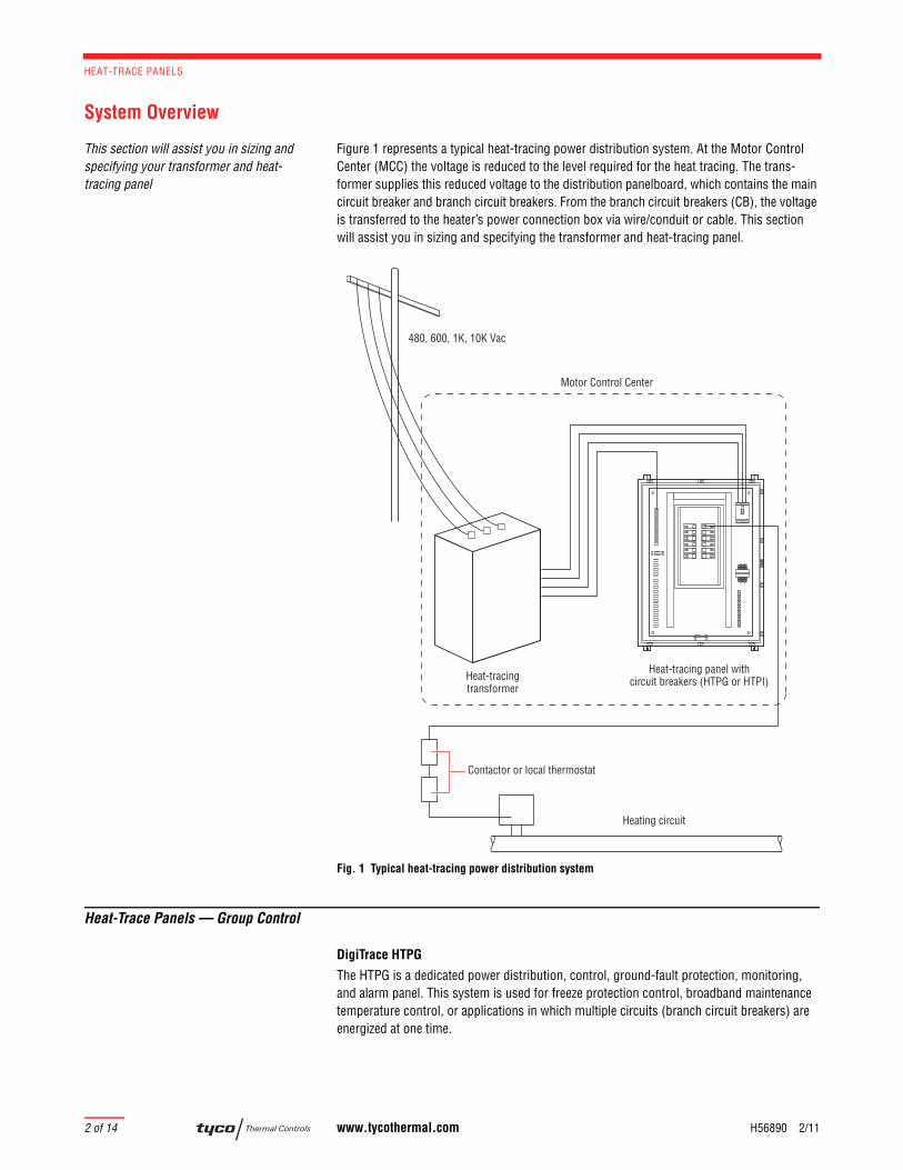
Figure 1 represents a typical heat-tracing power distribution system. At the Motor Control Center (MCC) the voltage is reduced to the level required for the heat tracing. The trans-former supplies this reduced voltage to the distribution panelboard, which contains the main circuit breaker and branch circuit breakers. From the branch circuit breakers (CB), the voltage is transferred to the heater’s power connection box via wire/conduit or cable. This section will assist you in sizing and specifying the transformer and heat-tracing panel.
Fig. 1 Typical heat-tracing power distribution system
Heat-Trace Panels — Group Control
DigiTrace HTPG
The HTPG is a dedicated power distribution, control, ground-fault protection, monitoring, and alarm panel. This system is used for freeze protection control, broadband maintenance temperature control, or applications in which multiple circuits (branch circuit breakers) are energized at one time.
Heat-tracingtransformer
Heat-tracing panel withcircuit breakers (HTPG or HTPI)
Contactor or local thermostat
480, 600, 1K, 10K Vac
Heating circuit
Motor Control Center
System Overview
H56890 2/11 www.tycothermal.com 3 of 14
1.Self-Regulat-ing Cables
2.Power-
Limiting
Cables
3.Mineral
Insulated Cables
4.Longline Heating
5.TubingBundles
6.TankHeating
7.Snow and
Ice8.Control and
Monitoring
9.Heat-Trace Panels
10.Engineered Products
11.Steam-
Tracing System
s
12.Technical Data Sheets
13.Appendixes14.Index
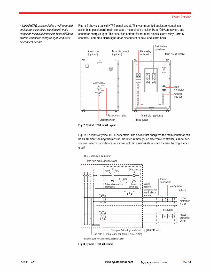
A typical HTPG panel includes a wall-mounted enclosure, assembled panelboard, main contactor, main circuit breaker, Hand/Off/Auto switch, contactor-energize light, and door disconnect handle.
Figure 2 shows a typical HTPG panel layout. This wall-mounted enclosure contains an assembled panelboard, main contactor, main circuit breaker, Hand/Off/Auto switch, and contactor-energize light. The panel has options for terminal blocks, alarm relay (form C contacts), common alarm light, door disconnect handle, and alarm horn.
Fig. 2 Typical HTPG panel layout
Figure 3 depicts a typical HTPG schematic. The device that energizes the main contactor can be an ambient sensing thermostat (mounted remotely), an electronic controller, a snow sen-sor controller, or any device with a contact that changes state when the heat tracing is ener-gized.
Fig. 3 Typical HTPG schematic
A
COMMON ALARMPUSH TO ACKNOWLEDGE
HAND/OFF/AUTO
1
2
3
4
5
6
7
8
9
10
11
12
Main circuit breakerAlarm relay(optional)
Maincontactor
Distributionpanelboard
Fuse holderSelector switch
Push-to-test lights
C
POWER ON
TB 1
TB 2
ARR
Groundbus bar
Terminals - (optional)
Alarm horn(optional)
Door disconnect(optional)
N
Three-pole main circuit breaker
Three-pole main contactor
One-pole 30-mA ground-fault trip (120/277 Vac)
Panelenergized
Contactorcoil
C NC
External controller/thermostat*
Hand AutoOff
Alarmremoteannunciation(with alarm option)
Power connection
Heating cable
Two-pole 30-mA ground-fault trip (208/240 Vac)
Freeze-protectioncircuit
Freeze-protectioncircuit
End seal
Braid/pipe
* External controller/thermostat sold separately
HEAT-TRACE PANELS
4 of 14 www.tycothermal.com H56890 2/11
Heat-Trace Panels — Individual Control
DigiTrace HTPI
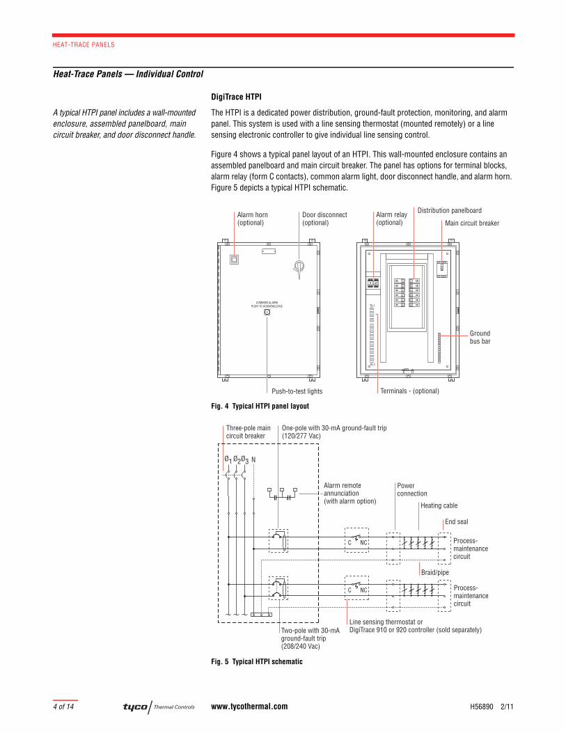
A typical HTPI panel includes a wall-mounted enclosure, assembled panelboard, main circuit breaker, and door disconnect handle.
The HTPI is a dedicated power distribution, ground-fault protection, monitoring, and alarm panel. This system is used with a line sensing thermostat (mounted remotely) or a line sensing electronic controller to give individual line sensing control.
Figure 4 shows a typical panel layout of an HTPI. This wall-mounted enclosure contains an assembled panelboard and main circuit breaker. The panel has options for terminal blocks, alarm relay (form C contacts), common alarm light, door disconnect handle, and alarm horn. Figure 5 depicts a typical HTPI schematic.
Fig. 4 Typical HTPI panel layout
Fig. 5 Typical HTPI schematic
A
COMMON ALARMPUSH TO ACKNOWLEDGE
1
2
3
4
5
6
7
8
9
10
11
12
Main circuit breakerAlarm relay(optional)
Distribution panelboard
Push-to-test lights
TB 1
TB 2
ARR
Groundbus bar
Terminals - (optional)
Alarm horn(optional)
Door disconnect(optional)
NØ1
Three-pole main circuit breaker
C NC
Ø3Ø2
Power connection
Heating cable
One-pole with 30-mA ground-fault trip(120/277 Vac)
Two-pole with 30-mAground-fault trip(208/240 Vac)
C NC
Alarm remoteannunciation(with alarm option)
Process-maintenancecircuit
Process-maintenancecircuit
End seal
Braid/pipe
Line sensing thermostat or DigiTrace 910 or 920 controller (sold separately)
Approvals and Certifications
H56890 2/11 www.tycothermal.com 5 of 14
1.Self-Regulat-ing Cables
2.Power-
Limiting
Cables
3.Mineral
Insulated Cables
4.Longline Heating
5.TubingBundles
6.TankHeating
7.Snow and
Ice8.Control and
Monitoring
9.Heat-Trace Panels
10.Engineered Products
11.Steam-
Tracing System
s
12.Technical Data Sheets
13.Appendixes14.Index
Approvals and Certifications
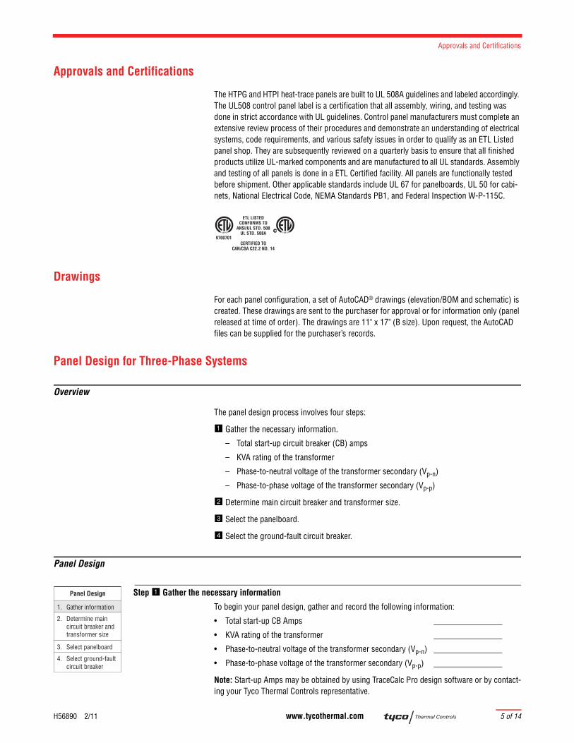
The HTPG and HTPI heat-trace panels are built to UL 508A guidelines and labeled accordingly. The UL508 control panel label is a certification that all assembly, wiring, and testing was done in strict accordance with UL guidelines. Control panel manufacturers must complete an extensive review process of their procedures and demonstrate an understanding of electrical systems, code requirements, and various safety issues in order to qualify as an ETL Listed panel shop. They are subsequently reviewed on a quarterly basis to ensure that all finished products utilize UL-marked components and are manufactured to all UL standards. Assembly and testing of all panels is done in a ETL Certified facility. All panels are functionally tested before shipment. Other applicable standards include UL 67 for panelboards, UL 50 for cabi-nets, National Electrical Code, NEMA Standards PB1, and Federal Inspection W-P-115C.
Drawings
For each panel configuration, a set of AutoCAD® drawings (elevation/BOM and schematic) is created. These drawings are sent to the purchaser for approval or for information only (panel released at time of order). The drawings are 11" x 17" (B size). Upon request, the AutoCAD files can be supplied for the purchaser’s records.
Panel Design for Three-Phase Systems
Overview
The panel design process involves four steps:
Gather the necessary information.
– Total start-up circuit breaker (CB) amps
– KVA rating of the transformer
– Phase-to-neutral voltage of the transformer secondary (Vp-n)
– Phase-to-phase voltage of the transformer secondary (Vp-p)
Determine main circuit breaker and transformer size.
Select the panelboard.
Select the ground-fault circuit breaker.
Panel Design
Step Gather the necessary information
To begin your panel design, gather and record the following information:
• Total start-up CB Amps
• KVA rating of the transformer
• Phase-to-neutral voltage of the transformer secondary (Vp-n)
• Phase-to-phase voltage of the transformer secondary (Vp-p)
Note: Start-up Amps may be obtained by using TraceCalc Pro design software or by contact-ing your Tyco Thermal Controls representative.
ETL LISTEDCONFORMS TO
ANSI/UL STD. 508UL STD. 508A
CERTIFIED TOCAN/CSA C22.2 NO. 14
9700701
Panel Design
2. Determine main circuit breaker and transformer size
3. Select panelboard
4. Select ground-fault circuit breaker
1. Gather information

HEAT-TRACE PANELS
6 of 14 www.tycothermal.com H56890 2/11
Step Determine main circuit breaker and transformer size
MAIN BREAKER SIZING
The purpose of the main circuit breaker is to protect the panelboard bussing, the transformer, and the wiring between the transformer and the panelboard. The main breaker also provides a way to disconnect power to the panelboard for maintenance purposes. Table 1, page 7, shows the maximum size main circuit breaker that can be used with each size transformer. Choose the appropriate main circuit breaker based upon your application.
TRANSFORMER SIZING
Transformers must be sized for the start-up load. This ensures that the main breaker, which protects the transformer, is large enough to take the start-up currents produced by heaters that have transient currents, such as self-regulating heaters. For most applications, this is based on the total start-up current. The formula for calculating minimum transformer rating is:
Where: KVA = KVA rating of the transformer
SF = Safety factor (allowance for spare capacity)
IT = Total start-up current
Vp-n = Phase-to-neutral voltage of the transformer secondary
Vp-p = Phase-to-phase voltage of the transformer secondary
After you have applied the above formula, go to Table 1 and choose the next largest standard transformer.
Note: The above formulas are based upon the assumption that the transformer is perfectly balanced and the entire panelboard will be energized at the same minimum ambient temper-ature for which the branch circuit breakers were sized.
Note regarding transformer primary protection: In most cases, the customer will provide the primary main circuit breaker. However, if you must provide the main circuit breaker on the primary side, the formula is:
Where: KVA = KVA rating of the transformer
1.25 = NEC factor
Vp-p = Phase-to-phase voltage supplying transformer
Panel Design
2. Determine main circuit breaker and transformer size
3. Select panelboard
4. Select ground-fault circuit breaker
1. Gather information
Vp-n x IT x SF
1000= KVA or
Vp-p x IT x SF
1000 x 1.73= KVA
KVA x 1000 x 1.25
Vp-p x 1.73= Next largest standard breaker
Panel Design for Three-Phase Systems
H56890 2/11 www.tycothermal.com 7 of 14
1.Self-Regulat-ing Cables
2.Power-
Limiting
Cables
3.Mineral
Insulated Cables
4.Longline Heating
5.TubingBundles
6.TankHeating
7.Snow and
Ice8.Control and
Monitoring
9.Heat-Trace Panels
10.Engineered Products
11.Steam-
Tracing System
s
12.Technical Data Sheets
13.Appendixes14.Index
Step Select the panelboard
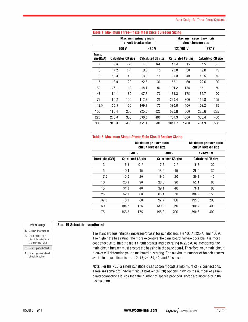
The standard bus ratings (amperage/phase) for panelboards are 100 A, 225 A, and 400 A. The higher the bus rating, the more expensive the panelboard. Where possible, it is most cost-effective to limit the main circuit breaker and bus rating to 225 A. As mentioned, the main circuit breaker must protect the bussing in the panelboard. Therefore, your main circuit breaker will determine your panelboard bus rating. The maximum number of branch spaces available in panelboards are: 12, 18, 24, 30, 42, and 54 spaces.
Note: Per the NEC, a single panelboard can accommodate a maximum of 42 connections. There are some ground-fault circuit breaker (GFCB) options in which the number of panel-board connections is less than the number of spaces provided. These are discussed in the next section.
Table 1 Maximum Three-Phase Main Circuit Breaker Sizing
Maximum primary maincircuit breaker size
Maximum secondary maincircuit breaker size
600 V 480 V 120/208 V 277 V
Trans. size (KVA) Calculated CB size Calculated CB size Calculated CB size Calculated CB size
3 3.6 4-F 4.5 6-F 10.4 15 4.5 6-F
6 7.2 9-F 9.0 15 20.8 30 9.0 15
9 10.8 15 13.5 15 31.3 40 13.5 15
15 18.0 20 22.6 30 52.1 60 22.6 30
30 36.1 40 45.1 50 104.2 125 45.1 50
45 54.1 60 67.7 70 156.3 175 67.7 70
75 90.2 100 112.8 125 260.4 300 112.8 125
112.5 135.3 150 169.1 175 390.6 400 169.2 175
150 180.4 200 225.5 225 520.8 600 225.6 225
225 270.6 300 338.3 400 781.3 800 338.4 400
300 360.8 400 451.1 500 1041.7 1200 451.3 500
Table 2 Maximum Single-Phase Main Circuit Breaker Sizing
Maximum primary main circuit breaker size
Maximum primary main circuit breaker size
600 V 480 V 120/240 V
Trans. size (KVA) Calculated CB size Calculated CB size Calculated CB size
3 6.3 9-F 7.8 9-F 15.6 20
5 10.4 15 13.0 15 26.0 30
7.5 15.6 20 19.5 20 39.1 40
10 20.8 30 26.0 30 52.1 60
15 31.3 40 39.1 40 78.1 80
25 52.1 60 65.1 70 130.2 150
37.5 78.1 80 97.7 100 195.3 200
50 104.2 125 130.2 150 260.4 300
75 156.3 175 195.3 200 390.6 400
Panel Design
2. Determine main circuit breaker and transformer size
3. Select panelboard
4. Select ground-fault circuit breaker
1. Gather information
HEAT-TRACE PANELS
8 of 14 www.tycothermal.com H56890 2/11
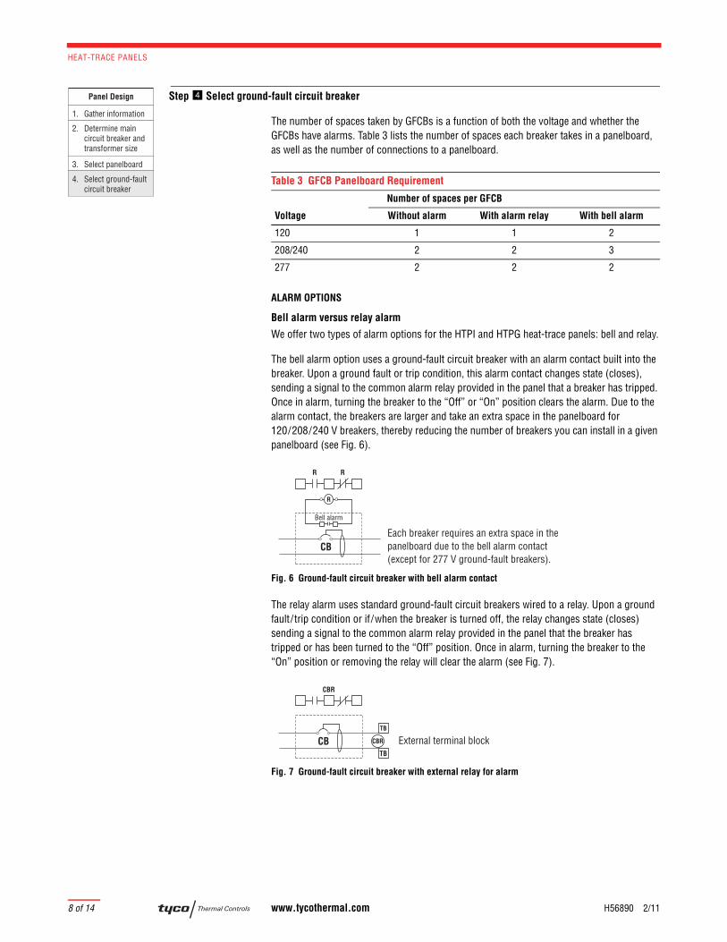
Step Select ground-fault circuit breaker
The number of spaces taken by GFCBs is a function of both the voltage and whether the GFCBs have alarms. Table 3 lists the number of spaces each breaker takes in a panelboard, as well as the number of connections to a panelboard.
ALARM OPTIONS
Bell alarm versus relay alarm
We offer two types of alarm options for the HTPI and HTPG heat-trace panels: bell and relay.
The bell alarm option uses a ground-fault circuit breaker with an alarm contact built into the breaker. Upon a ground fault or trip condition, this alarm contact changes state (closes), sending a signal to the common alarm relay provided in the panel that a breaker has tripped. Once in alarm, turning the breaker to the “Off” or “On” position clears the alarm. Due to the alarm contact, the breakers are larger and take an extra space in the panelboard for 120/208/240 V breakers, thereby reducing the number of breakers you can install in a given panelboard (see Fig. 6).
Fig. 6 Ground-fault circuit breaker with bell alarm contact
The relay alarm uses standard ground-fault circuit breakers wired to a relay. Upon a ground fault/trip condition or if/when the breaker is turned off, the relay changes state (closes) sending a signal to the common alarm relay provided in the panel that the breaker has tripped or has been turned to the “Off” position. Once in alarm, turning the breaker to the “On” position or removing the relay will clear the alarm (see Fig. 7).
Fig. 7 Ground-fault circuit breaker with external relay for alarm
Panel Design
2. Determine main circuit breaker and transformer size
3. Select panelboard
4. Select ground-fault circuit breaker
1. Gather information
Table 3 GFCB Panelboard Requirement
Number of spaces per GFCB
Voltage Without alarm With alarm relay With bell alarm
120 1 1 2
208/240 2 2 3
277 2 2 2
Each breaker requires an extra space in thepanelboard due to the bell alarm contact (except for 277 V ground-fault breakers).
Bell alarm
RR
CB
R
CBR
CBR
TB
CBTB
External terminal block
Product Selection
H56890 2/11 www.tycothermal.com 9 of 14
1.Self-Regulat-ing Cables
2.Power-
Limiting
Cables
3.Mineral
Insulated Cables
4.Longline Heating
5.TubingBundles
6.TankHeating
7.Snow and
Ice8.Control and
Monitoring
9.Heat-Trace Panels
10.Engineered Products
11.Steam-
Tracing System
s
12.Technical Data Sheets
13.Appendixes14.Index
Product Selection
HTPG Overview
The HTPG selection process involves two steps:
Gather the necessary information:
– Voltage
– Panelboard size
– Circuit breaker type and rating
– Number of circuit breakers (availability per voltage)
– Type of enclosure
– Main circuit breaker and contactor
– Options
Assemble the catalog number.
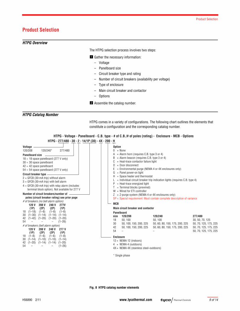
HTPG Catalog Number
HTPG comes in a variety of configurations. The following chart outlines the elements that constitute a configuration and the corresponding catalog number.
Fig. 8 HTPG catalog number elements
HTPG - 277/480 - 30 - 2 - 14/1P (30) - 4X - 200 - HHTPG - Voltage - Panelboard - C.B. type - # of C.B./# of poles (rating) - Enclosure - MCB - Options
Voltage120/208 120/240* 277/480 Panelboard size 18 = 18 space panelboard (277 V only) 30 = 30 space panelboard 42 = 42 space panelboard54 = 54 space panelboard (277 V only)Circuit breaker type2 = GFCB (30-mA trip) without alarm3 = GFCB (30-mA trip) with bell alarm4 = GFCB (30-mA trip) with relay alarm (includes terminal block option). Not available for 277 VNumber of circuit breakers/number of poles (circuit breaker rating) see prior page# of breakers (no bell alarm option) 120 V 208 V 240 V 277V (1P) (2P) (2P) (1P) 18 (1–18) (1–8) (1–8) (1–8)30 (1–30) (1–14) (1–14) (1–14)42 (1–42) (1–20) (1–20) (1–20)54 – – – (1–26) # of breakers (bell alarm option) 120 V 208 V 240 V 277 V (1P) (2P) (2P) (1P)18 (1–8) (1–6) (1–6) (1–8)30 (1–14) (1–10) (1–10) (1–14)42 (1–20) (1–14) (1–14) (1–20) 54 – – – (1–26)
Option0 = NoneA = Alarm horn (requires C.B. type 3 or 4)B = Alarm beacon (requires C.B. type 3 or 4)C = Heat-trace contactor failure lightD = Door disconnectE = Environmental purge (NEMA 4 or 4X enclosures only)G = Panel power-on lightH = Space heater and thermostatL = Individual circuit breaker trip indication lights (requires C.B. type 4)P = Heat-trace energized lightT = Terminal blocks (prewired)W = Wired for ETI controllerZ = Z-purge system (NEMA 4 or 4X enclosures only)SP = Special requirement: Must contain complete description of variance
MCBMain circuit breaker and contactorPanelboardsize 120/208 120/240 277/48018 50, 100 50, 100 30, 50, 70, 12530 50, 100, 150, 200, 225 50, 60, 80, 150, 175, 200, 225 50, 70, 125, 175, 22542 50, 100, 150, 200, 225 50, 60, 80, 150, 175, 200, 225 50, 70, 125, 175, 22554 – – 50, 70, 125, 175, 225
Enclosure12 = NEMA 12 (indoors)4 = NEMA 4 (outdoors)4X = NEMA 4X (stainless steel–outdoors)
* Single phase
HEAT-TRACE PANELS
10 of 14 www.tycothermal.com H56890 2/11
VOLTAGE
This is the voltage at which the heater is powered. If you have a combination of 120 V and 208 V heaters in the same panelboard, use 120/208 as the voltage. For 240 V, we are assum-ing that the voltage to the panelboard is single-phase (two phases and a neutral).
PANELBOARD SIZE
Specify the panelboard size you will require based on the number and type of circuit breakers required. You can specify a larger-than-required panelboard for spare space.
CIRCUIT BREAKER TYPE AND RATING
Specify the type of ground-fault breakers you require in the panelboard. In the parenthesis ( ), fill in the amperage of the breakers (refer to Fig. 8). If more than one amperage is required, then list all the amperages; for example, 3/2P(50), 4/2P(40).
NUMBER OF BREAKERS
Figure 8 lists the standard numbers of breakers we offer in a single panelboard. If you require more or fewer than the number of breakers shown, list the actual number of breakers required and we can provide a factory quote.
ENCLOSURE
Figure 8 shows the standard enclosures. If the panel will be located in a hazardous location (CID1 or CID2), specify 7 for a NEMA 7 explosion-proof enclosure; specify NEMA 4 or 4X enclosure for a Z-purge system and choose Z (Z purged) option.
MCB/CONTACTOR
If you require a main circuit breaker less than 100 A, state the required amperage. If you require a main circuit breaker larger than 225 A, state the required amperage and we can pro-vide a factory quote.
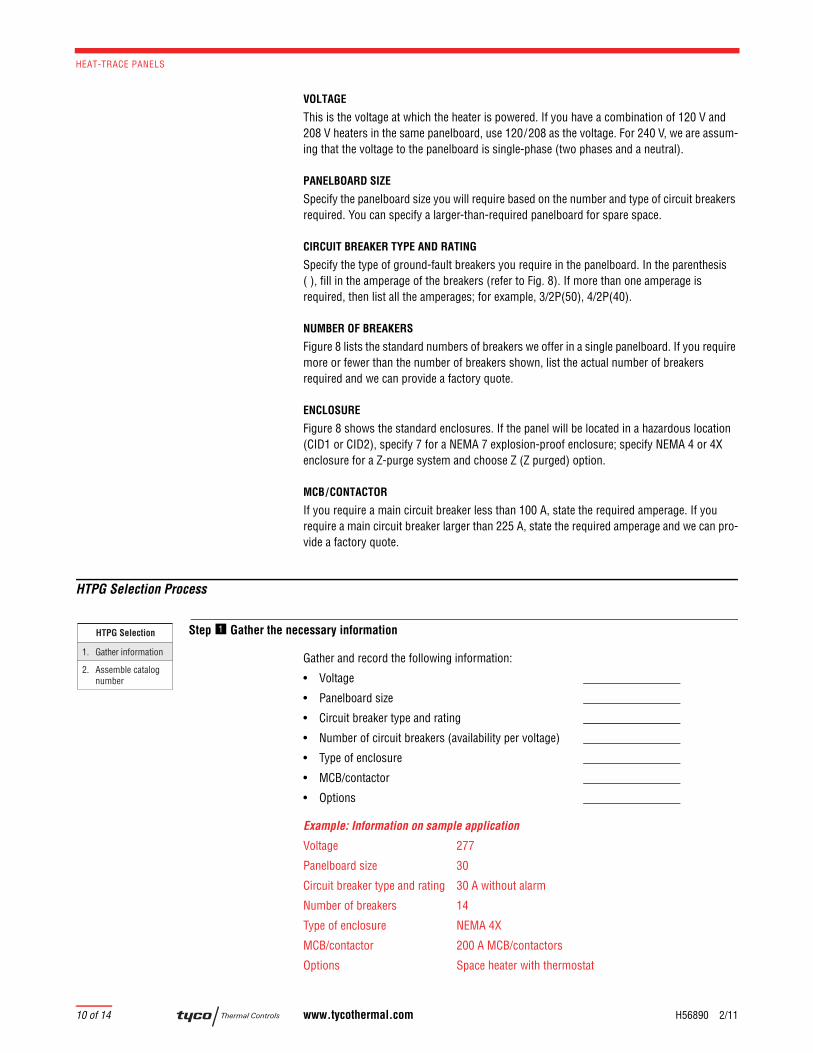
HTPG Selection Process
Step Gather the necessary information
Gather and record the following information:
• Voltage
• Panelboard size
• Circuit breaker type and rating
• Number of circuit breakers (availability per voltage)
• Type of enclosure
• MCB/contactor
• Options
Example: Information on sample application
Voltage 277
Panelboard size 30
Circuit breaker type and rating 30 A without alarm
Number of breakers 14
Type of enclosure NEMA 4X
MCB/contactor 200 A MCB/contactors
Options Space heater with thermostat
HTPG Selection
2. Assemble catalog number
1. Gather information
Product Selection
H56890 2/11 www.tycothermal.com 11 of 14
1.Self-Regulat-ing Cables
2.Power-
Limiting
Cables
3.Mineral
Insulated Cables
4.Longline Heating
5.TubingBundles
6.TankHeating
7.Snow and
Ice8.Control and
Monitoring
9.Heat-Trace Panels
10.Engineered Products
11.Steam-
Tracing System
s
12.Technical Data Sheets
13.Appendixes14.Index
Step Assemble the catalog number
Example: HTPG-277/480-30-2-14/1P(30)-4X-200-H
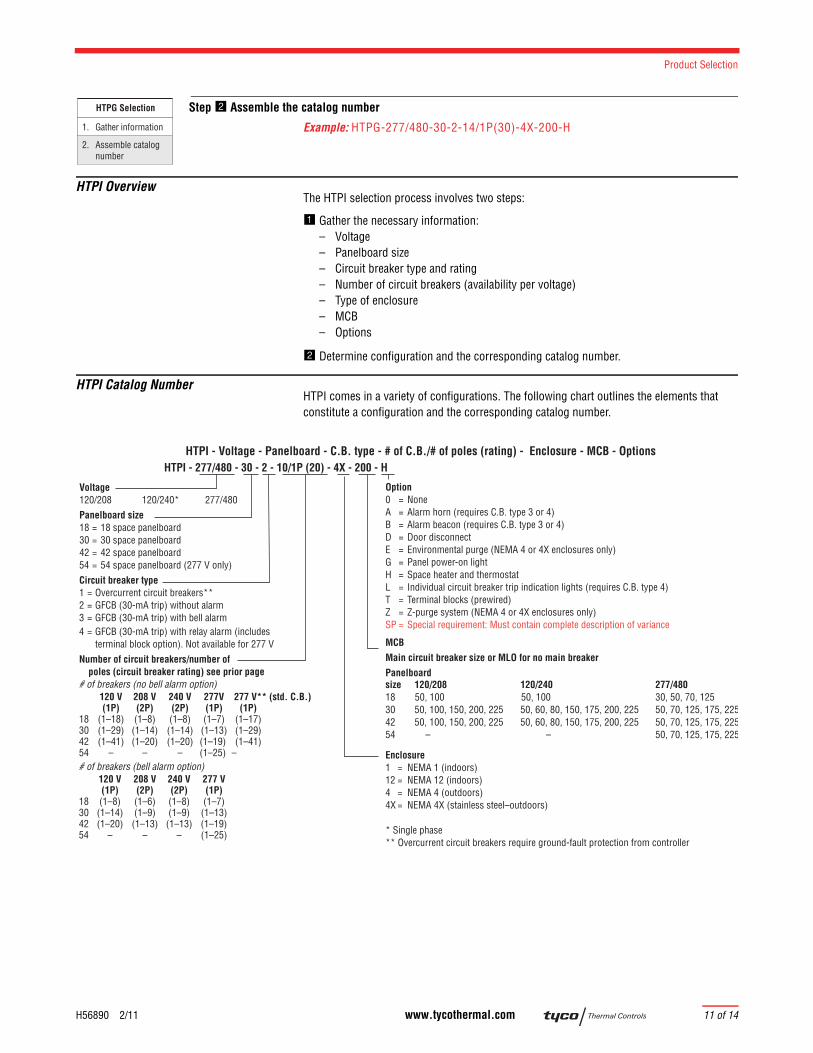
HTPI OverviewThe HTPI selection process involves two steps:
Gather the necessary information:– Voltage– Panelboard size– Circuit breaker type and rating– Number of circuit breakers (availability per voltage)– Type of enclosure– MCB – Options
Determine configuration and the corresponding catalog number.
HTPI Catalog NumberHTPI comes in a variety of configurations. The following chart outlines the elements that constitute a configuration and the corresponding catalog number.
HTPG Selection
2. Assemble catalog number
1. Gather information
HTPI - 277/480 - 30 - 2 - 10/1P (20) - 4X - 200 - HHTPI - Voltage - Panelboard - C.B. type - # of C.B./# of poles (rating) - Enclosure - MCB - Options
Voltage120/208 120/240* 277/480 Panelboard size 18 = 18 space panelboard 30 = 30 space panelboard 42 = 42 space panelboard54 = 54 space panelboard (277 V only)Circuit breaker type1 = Overcurrent circuit breakers**2 = GFCB (30-mA trip) without alarm3 = GFCB (30-mA trip) with bell alarm4 = GFCB (30-mA trip) with relay alarm (includes terminal block option). Not available for 277 VNumber of circuit breakers/number of poles (circuit breaker rating) see prior page# of breakers (no bell alarm option) 120 V 208 V 240 V 277V 277 V** (std. C.B.) (1P) (2P) (2P) (1P) (1P)18 (1–18) (1–8) (1–8) (1–7) (1–17)30 (1–29) (1–14) (1–14) (1–13) (1–29)42 (1–41) (1–20) (1–20) (1–19) (1–41)54 – – – (1–25) –# of breakers (bell alarm option) 120 V 208 V 240 V 277 V (1P) (2P) (2P) (1P)18 (1–8) (1–6) (1–8) (1–7)30 (1–14) (1–9) (1–9) (1–13)42 (1–20) (1–13) (1–13) (1–19) 54 – – – (1–25)
Option0 = NoneA = Alarm horn (requires C.B. type 3 or 4)B = Alarm beacon (requires C.B. type 3 or 4)D = Door disconnectE = Environmental purge (NEMA 4 or 4X enclosures only)G = Panel power-on lightH = Space heater and thermostatL = Individual circuit breaker trip indication lights (requires C.B. type 4)T = Terminal blocks (prewired)Z = Z-purge system (NEMA 4 or 4X enclosures only)SP = Special requirement: Must contain complete description of variance
MCBMain circuit breaker size or MLO for no main breakerPanelboardsize 120/208 120/240 277/48018 50, 100 50, 100 30, 50, 70, 12530 50, 100, 150, 200, 225 50, 60, 80, 150, 175, 200, 225 50, 70, 125, 175, 22542 50, 100, 150, 200, 225 50, 60, 80, 150, 175, 200, 225 50, 70, 125, 175, 22554 – – 50, 70, 125, 175, 225
Enclosure1 = NEMA 1 (indoors)12 = NEMA 12 (indoors)4 = NEMA 4 (outdoors)4X = NEMA 4X (stainless steel–outdoors)
* Single phase ** Overcurrent circuit breakers require ground-fault protection from controller

HEAT-TRACE PANELS
12 of 14 www.tycothermal.com H56890 2/11
Fig. 9 HTPI catalog number elements
VOLTAGE
This is the voltage at which the heater is powered. If you have a combination of 120 V and 208 V heaters in the same panelboard, use 120/208 as the voltage. For 240 V, we are assum-ing that the voltage to the panelboard is single-phase (two phases and a neutral).
PANELBOARD SIZE
Specify the panelboard size you will require based on the number and type of circuit breakers required.You can specify a larger-than-required panelboard for spare space.
CIRCUIT BREAKER TYPE AND RATING
Specify the type of breakers you require in the panelboard. If you choose a standard circuit breaker, the ground-fault protection function must come from the controller. In the parenthe-sis ( ), fill in the amperage of the breakers (refer to Figure 9). If more than one amperage is required, then list all the amperages; for example, 3/2P(50), 4/2P(40).
NUMBER OF BREAKERS
Figure 9 lists the standard numbers of breakers we offer in a single panelboard. If you require more or fewer than the number of breakers shown, list the actual number of breakers required and we can provide a factory quote.
ENCLOSURE
Figure 9 shows the standard enclosures. If the panel will be located in a hazardous location (CID1 or CID2), specify 7 for a NEMA 7 explosion-proof enclosure; specify NEMA 4 or 4X enclosure for a Z-purge enclosure and choose Z (Z purged) option.
MCB
If you require a main circuit breaker less than 100 A, state the required amperage. If you require a main circuit breaker larger than 225 A, state the required amperage and we can pro-vide a factory quote.
Product Selection
H56890 2/11 www.tycothermal.com 13 of 14
1.Self-Regulat-ing Cables
2.Power-
Limiting
Cables
3.Mineral
Insulated Cables
4.Longline Heating
5.TubingBundles
6.TankHeating
7.Snow and
Ice8.Control and
Monitoring
9.Heat-Trace Panels
10.Engineered Products
11.Steam-
Tracing System
s
12.Technical Data Sheets
13.Appendixes14.Index
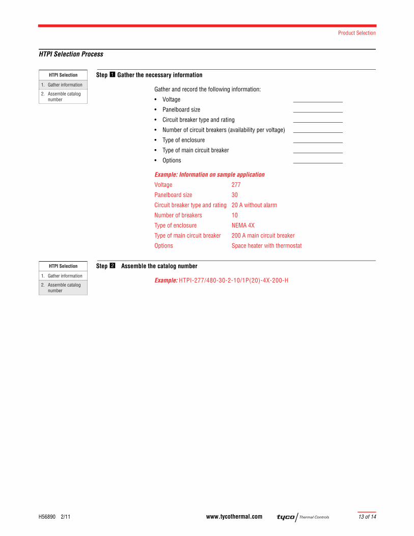
HTPI Selection Process
Step Gather the necessary information
Gather and record the following information:
• Voltage
• Panelboard size
• Circuit breaker type and rating
• Number of circuit breakers (availability per voltage)
• Type of enclosure
• Type of main circuit breaker
• Options
Example: Information on sample application
Voltage 277
Panelboard size 30
Circuit breaker type and rating 20 A without alarm
Number of breakers 10
Type of enclosure NEMA 4X
Type of main circuit breaker 200 A main circuit breaker
Options Space heater with thermostat
Step Assemble the catalog number
Example: HTPI-277/480-30-2-10/1P(20)-4X-200-H
HTPI Selection
2. Assemble catalog number
1. Gather information
HTPI Selection
2. Assemble catalog number
1. Gather information

HEAT-TRACE PANELS
14 of 14 www.tycothermal.com H56890 2/11

© 2
011
Tyc
o Th
erm
al C
ontro
ls L
LC
Important: All information, including illustrations, is believed to be reliable. Users, however, should independently evaluate the suitability of each product for their particular application. Tyco Thermal Controls makes no warranties as to the accuracy or completeness of the information, and disclaims any liability regarding its use. Tyco Thermal Controls' only obligations are those in the Tyco Thermal Controls Standard Terms and Conditions of Sale for this product, and in no case will Tyco Thermal Controls or its distributors be liable for any incidental, indirect, or consequential damages arising from the sale, resale, use, or misuse of the product. Specifications are subject to change without notice. In addition, Tyco Thermal Controls reserves the right to make changes—without notification to Buyer—to processing or materials that do not affect compliance with any applicable specification.
Worldwide HeadquartersTyco Thermal Controls7433 Harwin DriveHouston, TX 77036USATel: 800-545-6258Tel: 650-216-1526Fax: 800-527-5703Fax: [email protected]
Europe, Middle East, Africa (EMEA)Tyco Thermal ControlsRomeinse Straat 143001 LeuvenBelgië / BelgiqueTel: +32 16 213 511Fax: +32 16 213 603
CanadaTyco Thermal Controls250 West St.Trenton, OntarioCanada K8V 5S2Tel: 800-545-6258Fax: 800-527-5703
Latin AmericaTyco Thermal Controls7433 Harwin DriveHouston, TX 77036United StatesTel: 713-868-4800Tel: 713-735-8645Fax: 713-868-2333
Asia PacificTyco Thermal Controls20F, Innovation Building,1009 Yi Shan Rd,Shanghai 200233,P.R.ChinaTel: +86 21 2412 1688Fax: +86 21 5426 2937 / 5426 3167
Tyco, Alliance Integrated Systems, AMC, AutoMatrix, AutoSol, BTV, CapaciSense, Chemelex, DHSX, DigiTrace, DigiTrace logo, DigiTrace Supervisor, Duoterm, ElectroMelt, EM2XR, FHSM, FHSC, FlexFit, FlexiClic, Flowguard, FreezeTrace, FreezGard, Frostex, Flostex Plus, Frostguard, FroStop, FSE, Gardian, HAK, Handvise, HBTV, HCCL, HotCap, HQTV, HTPG, HTPI, HWAT, HXTV, IceStop, Interlock, Isocable, Isodrum, Isoheat, Isomantle, Isopad, Isopad Frostguard, Isopad logo, Isopanel, Isotape, Isotherm, JBM, JBS, K-Flex, K-Flex logo, KHE, KHH, KHL, KHP, KTV, Labsafe, LBTV, LHC, LHFV, LHRV, Metabond, Mini WinterGard, Miser WinterGard, MoniTrace, Multi-plus, NGC, PetroTrace, PLI, PolyMatrix, Pyro CiC, PyroFLX, Pyromaster, Pyropak, Pyrosil, PyroSizer, Pyrotenax, Pyrotenax Designer, Pyrotenax logo, QTVR, QuickNet, QuickNet logo, QuickStat, QuickTerm, RayClic, RaySol, RayStat, Retro WinterGard, RHS, RHSC, RHSM, RMM2, SBF, SBV, SC, SHC, Sheathmaster, ShowerGuard, ShrinkCap, ShrinkSeal, ShrinkSystems, ShrinkTool, ShrinkTube, SLBTV, SnoCalc, SnoCalc logo, STS, System 500, System 1850, System 1850-SE, System 2000, System 2200, T2, T2 logo, T2Blue, T2QuickNet, T2Red, T2Reflecta, TankCalc Plus, TempBus, Thermoheat, ThermoLimit, ThermoLine, Touch, Trac-Loc, TraceCalc, TraceCalc Net, TraceCalc Net logo, TraceCalc Pro logo, TraceGard 277, TraceMaster, Tracer, Tracer logo, TracerLynx, TracerLynx logo, TraceStat, TraceTek, TraceTek logo, TruckPak, VLBTV, VLKTV, VPL, We manage the heat you need, WinterGard, WinterGard logo, WinterGard Plus, WinterGard Wet, XL-Trace, XTV and Zero EMI are registered and/or unregistered trademarks of Tyco Thermal Controls LLC or its affiliates.
All other trademarks are the property of their respective owners.