
1 Ritva Keski-Kuha JWST Deputy OTE Manager May 19, 2009 JWST OTE Development Status...
21
1 Ritva Keski-Kuha Ritva Keski-Kuha JWST Deputy OTE Manager JWST Deputy OTE Manager May 19, 2009 May 19, 2009 JWST OTE Development Status JWST-PRES-012900
-
Upload
kenna-jarrells -
Category
Documents
-
view
227 -
download
3
Transcript of 1 Ritva Keski-Kuha JWST Deputy OTE Manager May 19, 2009 JWST OTE Development Status...
1
Ritva Keski-KuhaRitva Keski-KuhaJWST Deputy OTE ManagerJWST Deputy OTE Manager
May 19, 2009May 19, 2009
JWST OTE Development Status
JWST-PRES-012900

2
Topics
1. OTE Architecture Refresher
2. Mirror Status
3. Backplane Status
4. I&T Status
5. Schedule
6. Summary
3
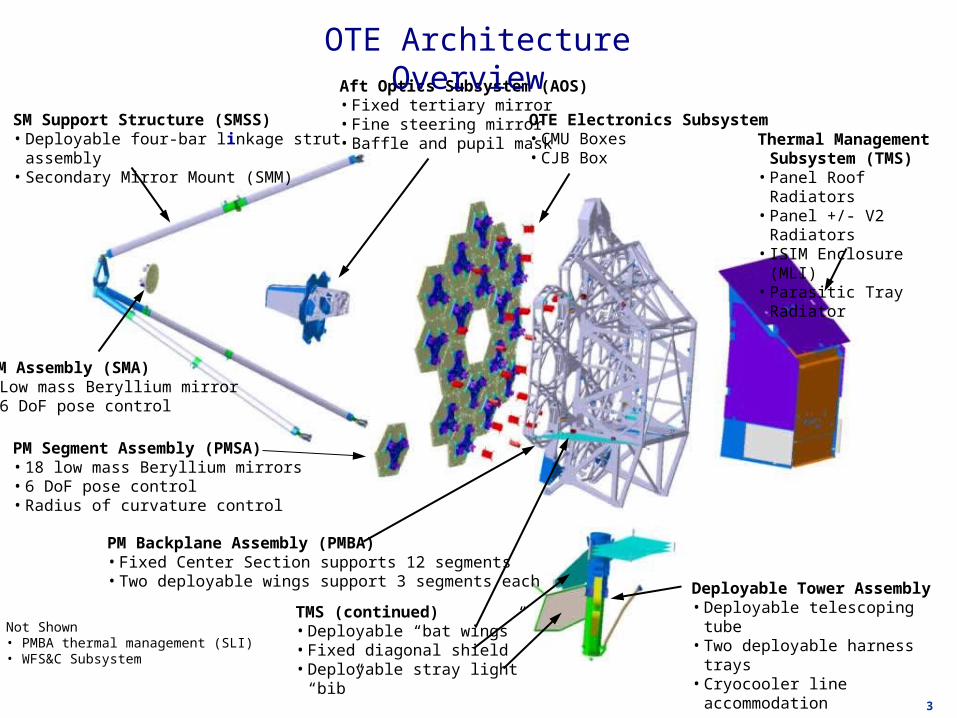
SM Support Structure (SMSS)• Deployable four-bar linkage strut assembly• Secondary Mirror Mount (SMM)
Thermal Management Subsystem (TMS)
• Panel Roof Radiators• Panel +/- V2 Radiators• ISIM Enclosure (MLI)• Parasitic Tray Radiator
Aft Optics Subsystem (AOS)• Fixed tertiary mirror• Fine steering mirror• Baffle and pupil mask
SM Assembly (SMA)• Low mass Beryllium mirror• 6 DoF pose control
PM Segment Assembly (PMSA)• 18 low mass Beryllium mirrors• 6 DoF pose control• Radius of curvature control
PM Backplane Assembly (PMBA)• Fixed Center Section supports 12 segments• Two deployable wings support 3 segments each Deployable Tower Assembly
• Deployable telescoping tube• Two deployable harness trays• Cryocooler line accommodation
TMS (continued)• Deployable “bat wings”• Fixed diagonal shield• Deployable stray light “bib”
Not Shown• PMBA thermal management (SLI)• WFS&C Subsystem
OTE Electronics Subsystem• CMU Boxes• CJB Box
OTE Architecture Overview
4
A1
B1
C6
A2
A3
A4
A5
A6 B2
B3
B4
B5
B6C1
C2
C3C4
C5
6.6 meters flat to flat1.32 meters
flat to flatA1
B1
C6
A2
A3
A4
A5
A6 B2
B3
B4
B5
B6C1
C2
C3C4
C5
A1
B1
C6
A2
A3
A4
A5
A6 B2
B3
B4
B5
B6C1
C2
C3C4
C5
A1
B1
C6
A2
A3
A4
A5
A6 B2
B3
B4
B5
B6C1
C2
C3C4
C5
6.6 meters flat to flat
6.6 meters flat to flat1.32 meters
flat to flat1.32 meters flat to flat
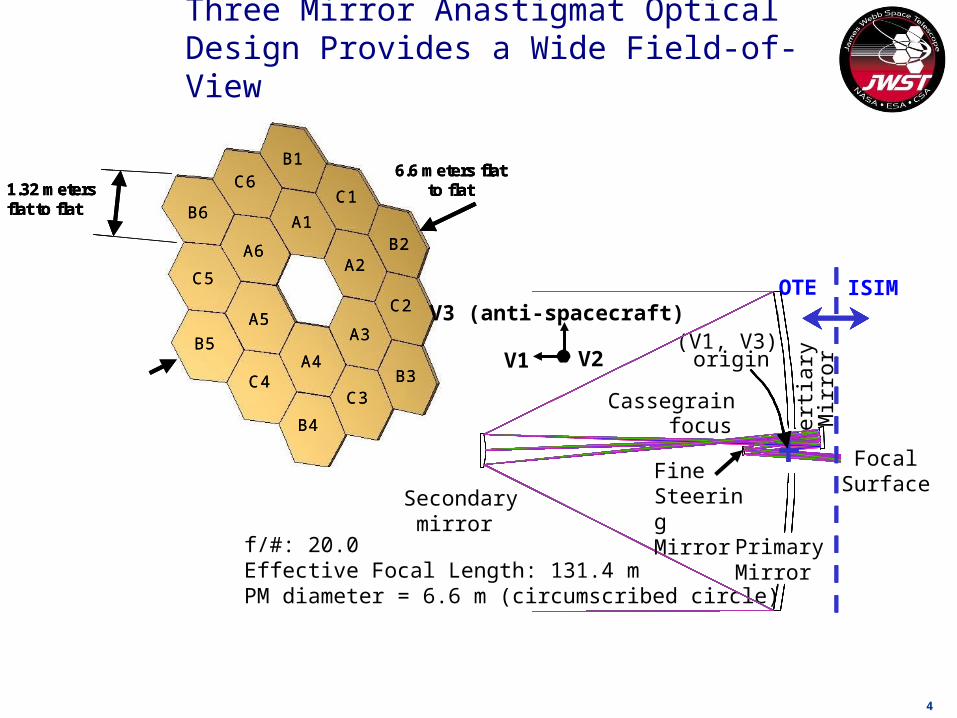
Three Mirror Anastigmat Optical Design Provides a Wide Field-of-View
Ter
tiary
M
irror
OTE ISIM
Cassegrain focus
(V1, V3) origin
f/#: 20.0 Effective Focal Length: 131.4 m PM diameter = 6.6 m (circumscribed circle)
V3 (anti-spacecraft)
V1 V2
Focal Surface
Primary Mirror
Secondary mirror
Fine Steering Mirror
5
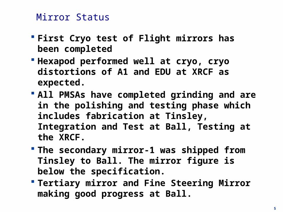
Mirror Status
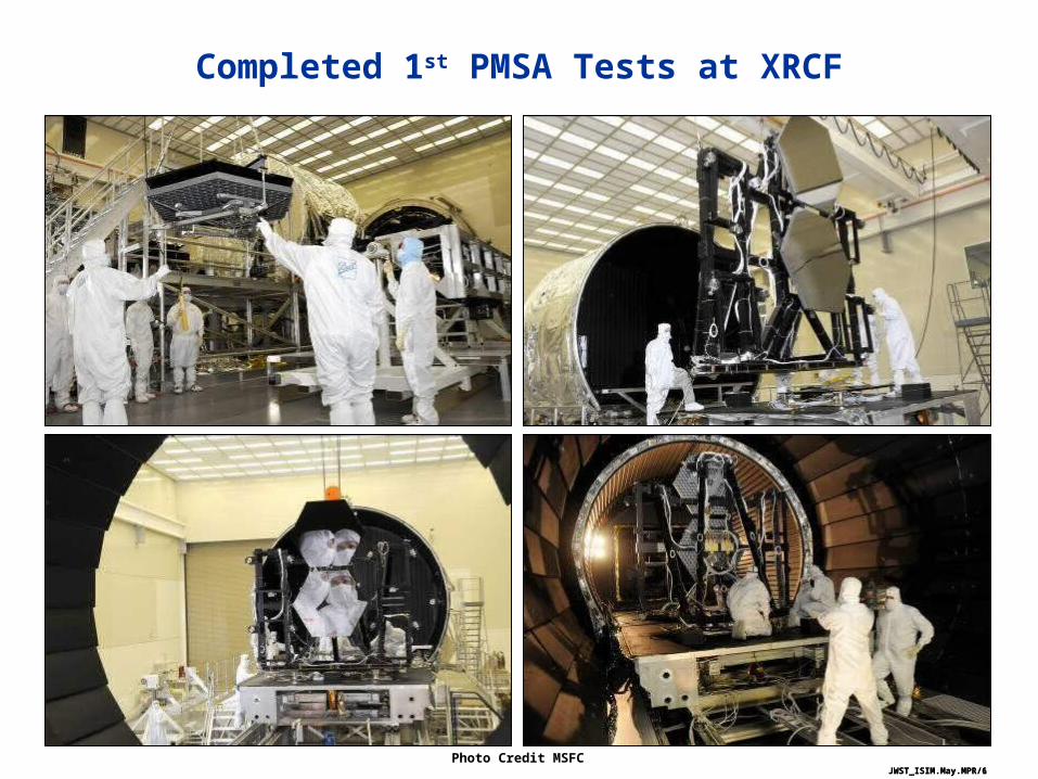
First Cryo test of Flight mirrors has been completed Hexapod performed well at cryo, cryo distortions of A1 and
EDU at XRCF as expected. All PMSAs have completed grinding and are in the polishing
and testing phase which includes fabrication at Tinsley, Integration and Test at Ball, Testing at the XRCF.
The secondary mirror-1 was shipped from Tinsley to Ball. The mirror figure is below the specification.
Tertiary mirror and Fine Steering Mirror making good progress at Ball.
JWST_ISIM.May.MPR/6
Completed 1st PMSA Tests at XRCF
Photo Credit MSFCJWST_ISIM.May.MPR/1
7
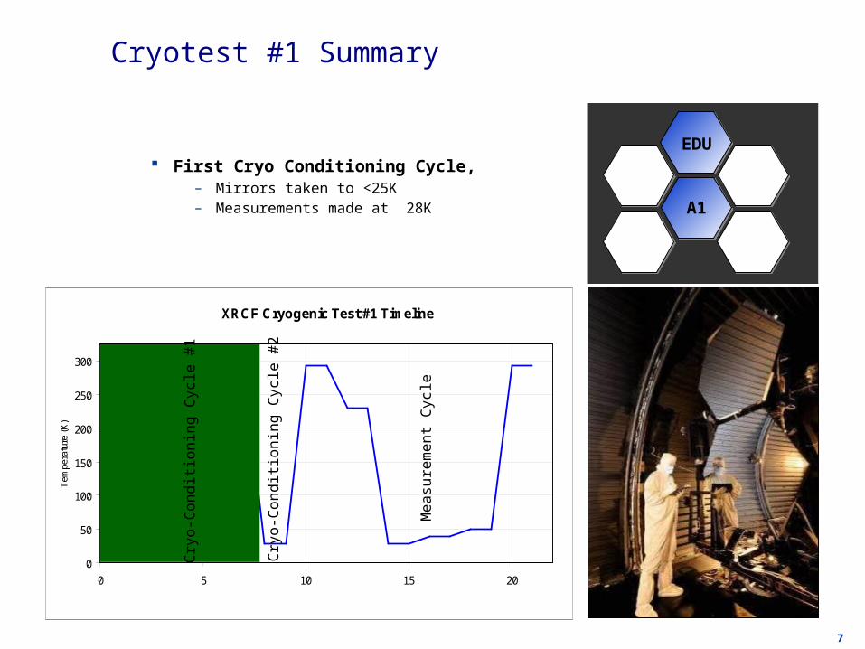
Cryotest #1 Summary
First Cryo Conditioning Cycle, – Mirrors taken to <25K– Measurements made at 28K A1
EDU
XRCF Cryogenic Test #1 Timeline
0
50
100
150
200
250
300
0 5 10 15 20
Tem
pera
ture
(K
)
Cry
o-C
ondit
ionin
g C
ycl
e #
1
Cry
o-C
ondit
ionin
g C
ycl
e #
2
Measu
rem
ent
Cycl
e

8
Cryo-Deformation of EDU
EDU CRYO(Piston, Tilt, Power, Astigmatism, Gravity Removed)
EDU AMBIENT(Piston, Tilt, Power, Astigmatism, & Gravity Removed)
Temperature = 292K
Dataset: 7040.407AB
Cryo-Deformation(Piston, Tilt, Power Removed) Astigmatism
RMS: 115.4 nm rms
Mid/Low FigureRMS: 82.0 nm rms
High Freq FigureRMS 25.0 nm rms
MEA
SU
REM
EN
TS
DIF
FER
EN
CE
Total Cryo-deformation = 142.7 nm rms
RoC Change -18.997 mm
mm-2.636As-Measured ROC
nm rms
nm rms182.0Figure
79.4Astigmatism
mm-3.832As-Measured ROC
nm rms
nm rms163.3Figure
124.7Astigmatism
Temperature = 29K
Dataset: 7040.410
9 of 240BATC MSR 04/29/09
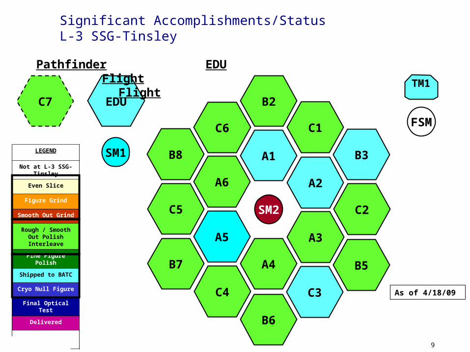
Significant Accomplishments/StatusL-3 SSG-Tinsley
As of 4/18/09
TM1
EDU
SM1
Pathfinder EDU Flight Flight
C7
LEGEND
Not at L-3 SSG-Tinsley
Even Slice
Figure Grind
Smooth Out Grind
Rough / Smooth Out Polish Interleave
Fine Figure Polish
Shipped to BATC
Cryo Null Figure
Final Optical Test
Delivered
– – – – – Pathfinder
C5
B8
C6
B3
C1
C2
A1
A6
A5
A2
C4
A3
A4
C3
B5
B6
B7
SM2
B2
FSM

10mjm-09-tms-0852
Secondary Mirror Assembly Progress
SM Hexapod ready for assembly to substrateSM Hexapod ready for assembly to substrateSM substrateSM substrate
Ball SM Test OpticsBall SM Test Optics Tinsley SM Test OpticsTinsley SM Test Optics

11mjm-09-tms-0852
Tertiary Mirror and Fine Steering Mirror
TM substrate and sub-benchTM substrate and sub-bench
TM testingTM testing
TM in optical test standTM in optical test stand
FSM in vibration testing
12mjm-09-tms-0852
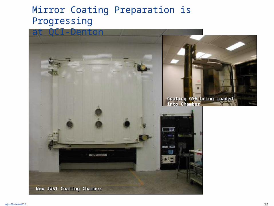
Mirror Coating Preparation is Progressingat QCI-Denton
New JWST Coating ChamberNew JWST Coating Chamber
Coating GSE being loaded into ChamberCoating GSE being loaded into Chamber
13
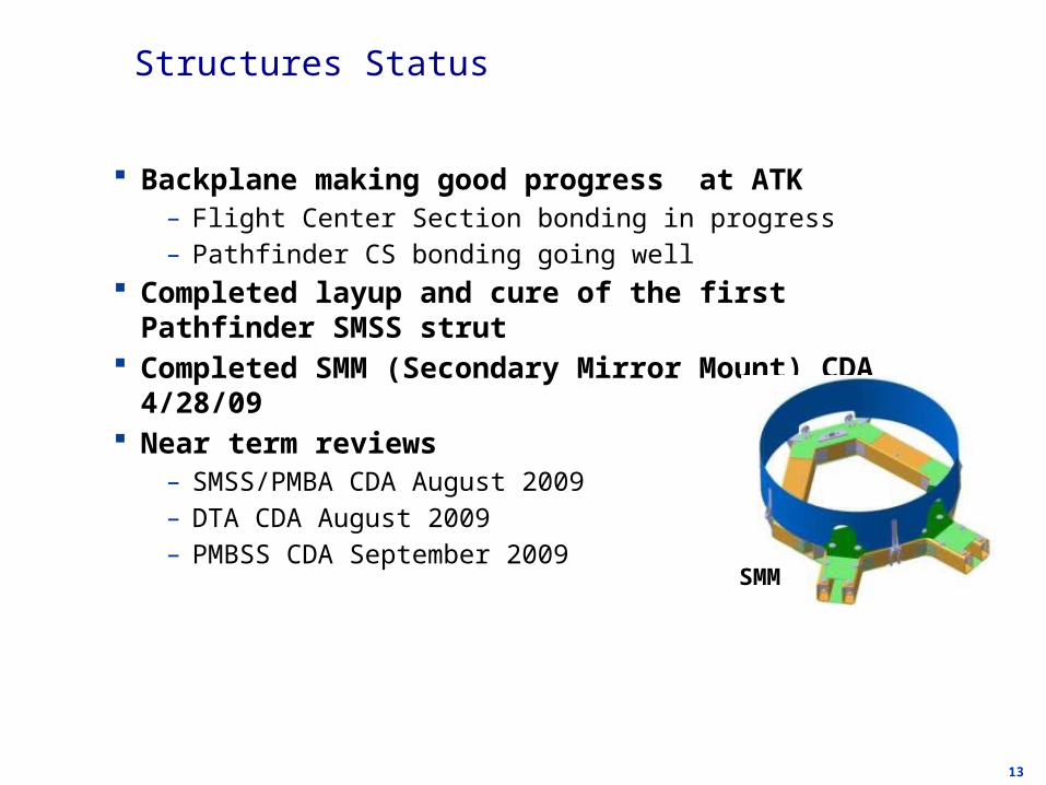
Structures Status
Backplane making good progress at ATK– Flight Center Section bonding in progress– Pathfinder CS bonding going well
Completed layup and cure of the first Pathfinder SMSS strut Completed SMM (Secondary Mirror Mount) CDA 4/28/09 Near term reviews
– SMSS/PMBA CDA August 2009– DTA CDA August 2009– PMBSS CDA September 2009
SMM
14
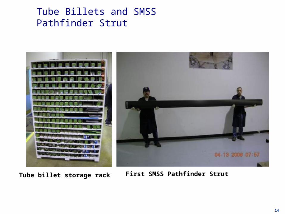
Tube Billets and SMSS Pathfinder Strut
Tube billet storage rack First SMSS Pathfinder Strut
15
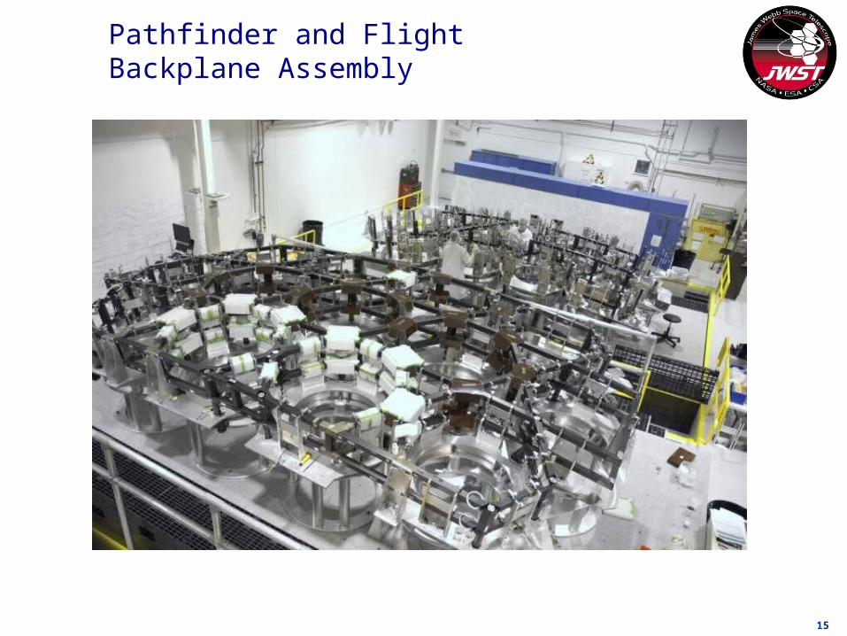
Pathfinder and Flight Backplane Assembly
16
I & T Status
Completed CDA for majority of the SSDIF Alignment and Integration Hardware and JSC Test Hardware.
Null lens optics have been ordered ACF#1 Skip Test execution starting in November 2009
– ACF Mirror Blanks are in procurement Chamber isolator demonstration is in progress. PIT Review scheduled for July 2009
17mjm-09-tms-0852
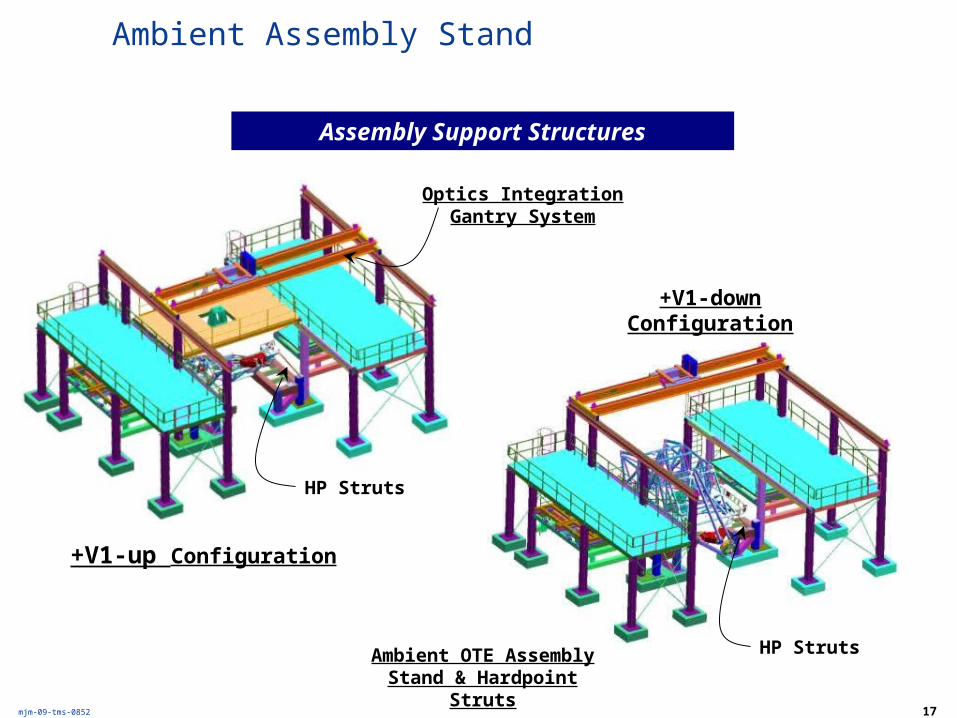
Ambient Assembly Stand
Assembly Support Structures
+V1-up Configuration
+V1-down Configuration
Ambient OTE Assembly Stand & Hardpoint Struts
HP Struts
HP Struts
Optics Integration Gantry System

18mjm-09-tms-0852
Test GSE Architecture and Subsystems
• Space Vehicle Thermal Simulator (SVTS) by NG
• Hardpoint Offloader Support System (HOSS)
Center of Curvature Optical Assembly (COCOA)
• COCI (MWL interferometer, null, calibration equipment)
Autocollimating Flat Mirrors (ACF Assembly)
• 3 ACFs (actuated motion)
• Rogue Path• Cryo Position Metrology• • Fiber fed PM Lights
• Down Rods• Upper Suspension Frame (USF)• Telescope Tension Rods
Optical Telescope Element (OTE Integrated Science Instrument Assembly (ISIM) – (OTIS)
• Isolation System
LN2 and Helium Cryogenic Shrouds
N
E
19mjm-09-tms-0852
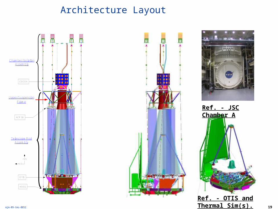
Architecture Layout
Chamber Isolation Assembly
Telescope Rod Assembly
ACF to PM 39.0 ft
(11.9 m)
OTIS
HOSS
COCOA
26.3 ft(8.0 m)
COCOA to PM
Distance52.1 ft
(15.9 m)
ACF 3X
Upper Suspension
Frame
+V1
+V2
56.2 ft(17.1 m)
Top of HOSS to GHe Shroud5.8 ft (1.8 m)
Port Flangeto
GHe Shroud89.4 ft
(27.2 m)
Ref. - JSC Chamber A
Ref. - OTIS and Thermal Sim(s).
20 of 240BATC MSR 04/29/09
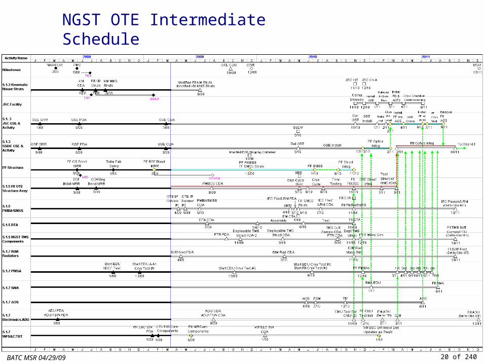
NGST OTE Intermediate Schedule
21
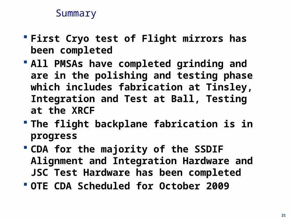
Summary
First Cryo test of Flight mirrors has been completed All PMSAs have completed grinding and are in the polishing
and testing phase which includes fabrication at Tinsley, Integration and Test at Ball, Testing at the XRCF
The flight backplane fabrication is in progress CDA for the majority of the SSDIF Alignment and Integration
Hardware and JSC Test Hardware has been completed OTE CDA Scheduled for October 2009