1 Remote Sensing and Image Processing: 5 Dr. Mathias (Mat) Disney UCL Geography Office: 301, 3rd...
24
1 Remote Sensing and Image Processing: 5 Dr. Mathias (Mat) Disney UCL Geography Office: 301, 3rd Floor, Chandler House Tel: 7670 4290 (x24290) Email: [email protected] www.geog.ucl.ac.uk/~mdisney
-
Upload
morris-barton -
Category
Documents
-
view
216 -
download
2
Transcript of 1 Remote Sensing and Image Processing: 5 Dr. Mathias (Mat) Disney UCL Geography Office: 301, 3rd...

1
Remote Sensing and Image Processing: 5
Dr. Mathias (Mat) Disney
UCL Geography
Office: 301, 3rd Floor, Chandler House
Tel: 7670 4290 (x24290)
Email: [email protected]
www.geog.ucl.ac.uk/~mdisney

2
EMR arriving at Earth•We now know how EMR spectrum is distributed
•Radiant energy arriving at Earth’s surface
•NOT blackbody, but close
•This lecture…..•Interactions of EMR with atmosphere
•scattering
•Atmospheric windows and choosing the “right” place for bands
•Interactions at the surface
•Scattering and angular effects

3
Departure from blackbody assumption
• Interaction with gases in the atmosphere– attenuation of solar radiation

4
Interactions with the atmosphere
•Notice that target reflectance is a function of
•Atmospheric irradiance
•reflectance outside target scattered into path
•diffuse atmospheric irradiance
•multiple-scattered surface-atmosphere interactions
From: http://www.geog.ucl.ac.uk/~mdisney/phd.bak/final_version/final_pdf/chapter2a.pdf
R1
target
R2
target
R3
target
R4
target

5
Interactions with the atmosphere: scattering
•Caused by presence of particles (soot, salt, etc.) and/or large gas molecules present in the atmosphere •Interact with EMR and cause to be redirected from original path. •Scattering amount depends on:
of radiation•abundance of particles or gases•distance the radiation travels through the atmosphere (path length)
After: http://www.ccrs.nrcan.gc.ca/ccrs/learn/tutorials/fundam/chapter1/chapter1_4_e.html

6
Atmospheric scattering 1: Rayleigh
•Particle size << of radiation•e.g. very fine soot and dust or N2, O2 molecules• Rayleigh scattering dominates shorter and in upper atmos.
•i.e. Longer scattered less (visible red scattered less than blue )•Hence during day, visible blue tend to dominate (shorter path length)•Longer path length at sunrise/sunset so proportionally more visible blue scattered out of path so sky tends to look more red•Even more so if dust in upper atmosphere•http://www.spc.noaa.gov/publications/corfidi/sunset/•http://www.nws.noaa.gov/om/educ/activit/bluesky.htm
After: http://www.ccrs.nrcan.gc.ca/ccrs/learn/tutorials/fundam/chapter1/chapter1_4_e.html

7
Atmospheric scattering 2: Mie
•Particle size of radiation•e.g. dust, pollen, smoke and water vapour •Affects longer than Rayleigh, BUT weak dependence on •Mostly in the lower portions of the atmosphere
•larger particles are more abundant•dominates when cloud conditions are overcast
•i.e. large amount of water vapour (mist, cloud, fog) results in almost totally diffuse illumination
After: http://www.ccrs.nrcan.gc.ca/ccrs/learn/tutorials/fundam/chapter1/chapter1_4_e.html

8
Atmospheric scattering 3: Non-selective
•Particle size >> of radiation•e.g. Water droplets and larger dust particles, •All affected about equally (hence name!)•Hence results in fog, mist, clouds etc. appearing white
•white = equal scattering of red, green and blue s
After: http://www.ccrs.nrcan.gc.ca/ccrs/learn/tutorials/fundam/chapter1/chapter1_4_e.html

9
Atmospheric absorption
•Other major interaction with signal•Gaseous molecules in atmosphere can absorb photons at various
•depends on vibrational modes of molecules•Very dependent on
•Main components are:•CO2, water vapour and ozone (O3)•Also CH4 ....
•O3 absorbs shorter i.e. protects us from UV radiation

10
Atmospheric “windows”
•As a result of strong dependence of absorption
•Some totally unsuitable for remote sensing as most radiation absorbed
Landsat TM bands in atmospheric windows

11
Atmospheric “windows”
• If you want to look at surface– Look in atmospheric windows where transmissions high
– BUT if you want to look at atmosphere ....pick gaps
• Very important when selecting instrument channels– Note atmosphere nearly transparent in wave i.e. can see through clouds!
– BIG advantage of wave remote sensing

12
Atmospheric “windows”
• Vivisble + NIR part of the spectrum– windows, roughly: 400-750, 800-1000, 1150-1300, 1500-1600, 2100-2250nm

13
Recap•Signal we measure contains atmospheric “contamination” (or information depending on your point of view!)
•Rayleigh (fine dust and gases), Mie (bigger particles) and non-selective scattering (water vapour and the rest)
•Perform atmospheric correction to get at surface signal
•Part of pre-processing steps (see later)
•So what happens at the surface?

14
Reflectance
•When EMR hits target (surface)
•Range of surface reflectance behaviour
•perfect specular (mirror-like) - incidence angle = exitance angle
•perfectly diffuse (Lambertian) - same reflectance in all directions independent of illumination angle)
From http://www.ccrs.nrcan.gc.ca/ccrs/learn/tutorials/fundam/chapter1/chapter1_5_e.html
Natural surfaces somewhere in
between
15
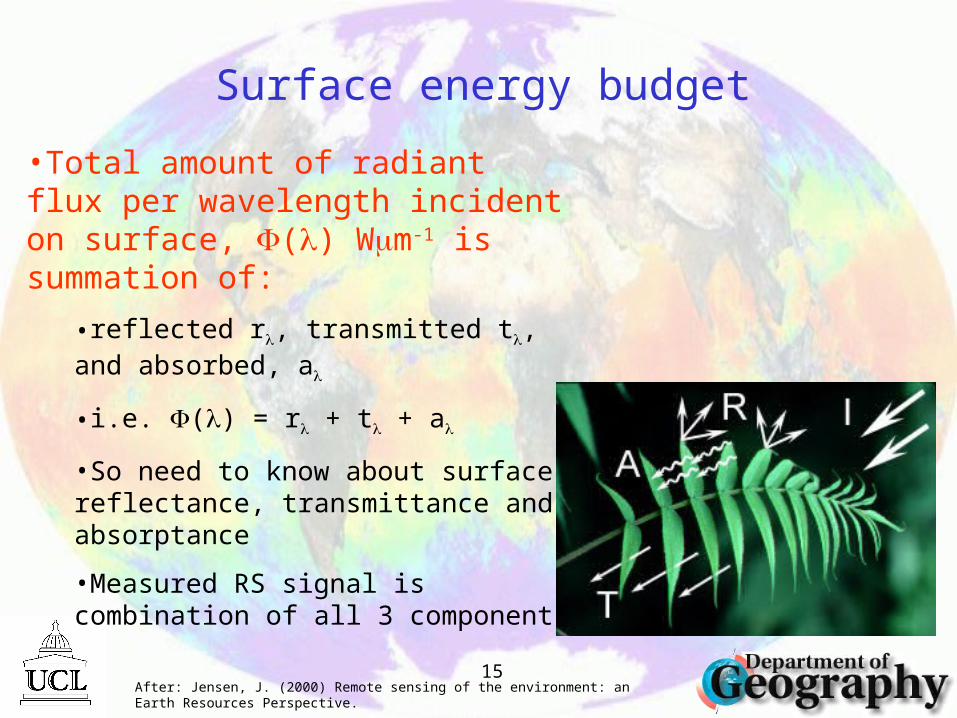
Surface energy budget
•Total amount of radiant flux per wavelength incident on surface, () Wm-1 is summation of:
•reflected r, transmitted t, and absorbed, a
•i.e. () = r + t + a
•So need to know about surface reflectance, transmittance and absorptance
•Measured RS signal is combination of all 3 components
After: Jensen, J. (2000) Remote sensing of the environment: an Earth Resources Perspective.

16
Angular distribution of reflectance
•Real surfaces usually display some degree of reflectance ANISOTROPY
•Lambertian surface is isotropic by definition
•Most surfaces have some level of anisotropy
•Described by Bidirectional Reflectance Distribution Function (BRDF)
From: http://www.geog.ucl.ac.uk/~mdisney/phd.bak/final_version/final_pdf/chapter2a.pdf
Figure 2.1 Four examples of surface reflectance: (a) Lambertian reflectance (b) non-Lambertian (directional) reflectance (c) specular (mirror-like) reflectance (d)
retro-reflection peak (hotspot).
(a) (b)
(c) (d)

17
Directional Information

18
Features of BRDF• Bowl shape
– increased scattering due to increased path length through canopy
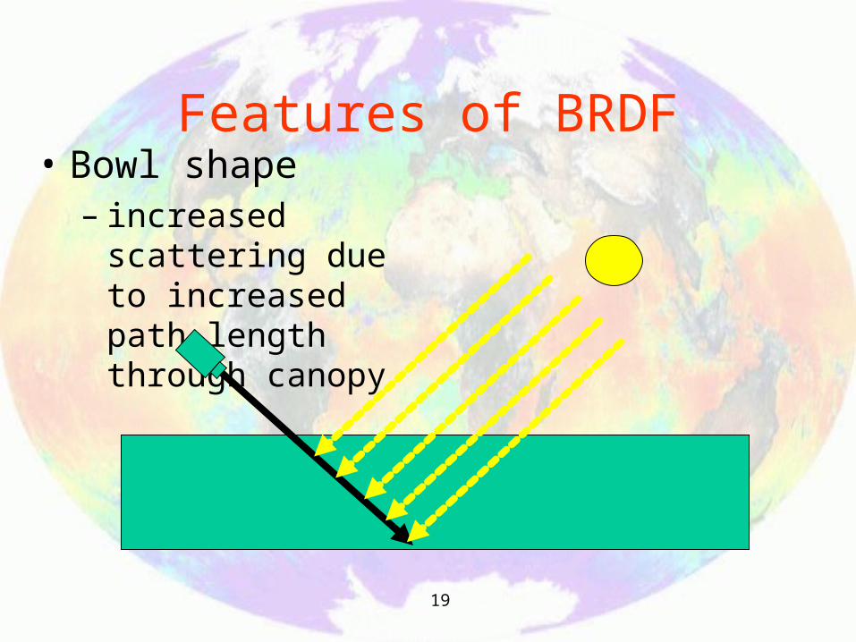
19
Features of BRDF• Bowl shape
– increased scattering due to increased path length through canopy

20

21
Features of BRDF• Hot Spot
– mainly shadowing minimum
– so reflectance higher

22

23
Directional reflectance: BRDF•Good explanation of BRDF:
•http://geography.bu.edu/brdf/brdfexpl.html

24
Summary• Top-of-atmosphere (TOA) signal is NOT target signal
– function of target reflectance
– plus atmospheric component (scattering, absorption)
– need to choose appropriate regions (atmospheric windows)
• Surface reflectance is anisotropic– i.e. looks different in different directions
– described by BRDF
– angular signal contains information on size, shape and distribution of objects on surface


![7670 CDC Concept Douche[1]](https://static.fdocuments.net/doc/165x107/5571fb16497959916993e9e1/7670-cdc-concept-douche1.jpg)