1 Quantum phosphors Observation of the photon cascade emission process for Pr 3+ - doped phosphors...
26
1 Quantum phosphors Observation of the photon cascade emission process for Pr 3+ -doped phosphors under vacuum ultraviolet (VUV) and X-ray excitation A.P. Vink 1,2 , E. van der Kolk 1 , P. Dorenbos 1 and C.W.E. van Eijk 1 1 Radiation Technology Group, Interfaculty Reactor Institute, Delft University of Technology, Mekelweg 15, 2629 JB Delft, The Netherlands 2 Chemical Sciences, Netherlands Organisation for Scientific Research, P.O. Box 93470, 2509 AL The Hague, The Netherlands Radiation Technology, Interfaculty Reactor Institute
-
Upload
april-tucker -
Category
Documents
-
view
247 -
download
0
Transcript of 1 Quantum phosphors Observation of the photon cascade emission process for Pr 3+ - doped phosphors...

1
Quantum phosphorsObservation of the photon cascade emission process for Pr3+-doped phosphors under vacuum ultraviolet
(VUV) and X-ray excitation
A.P. Vink1,2, E. van der Kolk1, P. Dorenbos1 and C.W.E. van Eijk1
1 Radiation Technology Group, Interfaculty Reactor Institute, Delft University of Technology,
Mekelweg 15, 2629 JB Delft, The Netherlands
2 Chemical Sciences, Netherlands Organisation for Scientific Research, P.O. Box 93470, 2509 AL
The Hague, The Netherlands
Radiation Technology, Interfaculty Reactor Institute

2
Outline 1. New generation lighting
2. Quantum cutting
3. Photon cascade emission with Pr3+
4. Selecting materials
5. Two types of emission in one material
6. Quantum cutting with X Rays
7. Energy transfer 1S0 emission
8. Conclusions

3
New generation lighting
120 130 140 150 160 170 180 190 2000,0
0,1
0,2
0,3
0,4
0,5
0,6
0,7
0,8
0,9
1,0
7.2eV
8.3eV
Inte
nsi
ty (
a.u
.)
Wavelength (nm)
• Commonly used TL lighting, mercury (254 nm emission) is used to excite a set of three phosphors
• Result: white light• Disadvantages: 1) mercury bad
for environment and 2) start-up time
• Alternative xenon-gas (emission around 172 nm)
• Result: new set of phosphors needed
4
New generation lighting
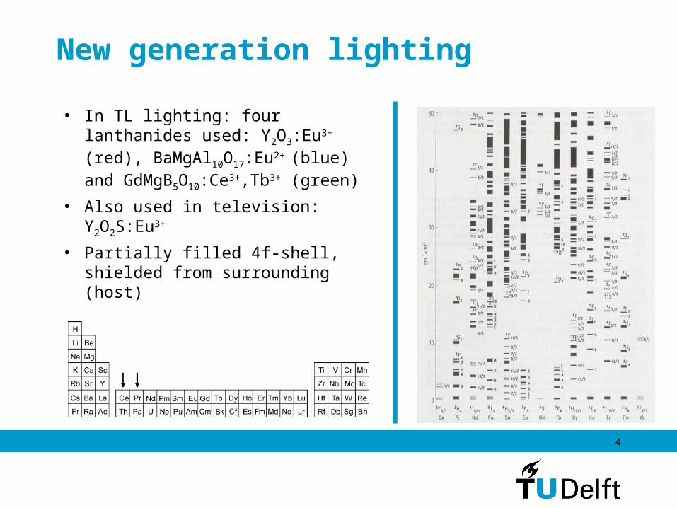
• In TL lighting: four lanthanides used: Y2O3:Eu3+ (red), BaMgAl10O17:Eu2+ (blue) and GdMgB5O10:Ce3+,Tb3+ (green)
• Also used in television: Y2O2S:Eu3+
• Partially filled 4f-shell, shielded from surrounding (host)
5
Quantum cutting
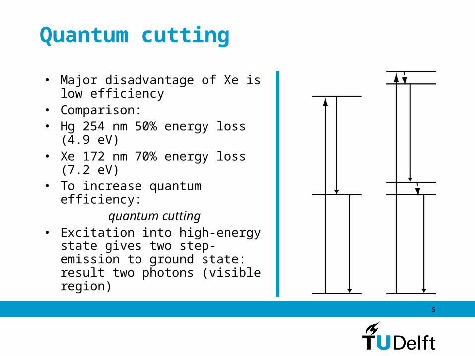
• Major disadvantage of Xe is low efficiency
• Comparison: • Hg 254 nm 50% energy loss
(4.9 eV) • Xe 172 nm 70% energy loss
(7.2 eV)• To increase quantum
efficiency:quantum cutting
• Excitation into high-energy state gives two step-emission to ground state: result two photons (visible region)

6
Photon cascade emission with Pr 3+
• Pr3+: [Xe] 4f2 (praseodymium)• Energy level scheme: 13 states
• Excitation into 1S0: two photons
• 1S0 level: weak absorption, excitation into 4f15d1 state, resulting in 1S0 → 1I6 (400 nm) and 3P0 → 3H4 (480 nm)
• Predicted by Dexter (1957), but discovered in 1974 by Sommerdijk (Philips) and Piper (GE) for YF3:Pr3+
0
10
20
30
40
50
60
4f15d
1
3F3,
3F4
3H6,
3F2
1G4
1D2
3P0
3P2
3P1,
1I6
1S0
3H5
3H4
Ene
rgy
(103 cm
-1)

7
Photon cascade emission with Pr 3+
• Material which shows PCE: SrAlF5:Pr3+
0
10
20
30
40
50
60
4f15d1
3F3,3F4
3H6,3F2
1G4
1D2
3P0
3P2
3P1,1I6
1S0
3H53H4
Ene
rgy
(103 cm
-1)
50 100 150 200 250 300 350 400 450 500 550 600 650 700
0,0
0,2
0,4
0,6
0,8
1,0
host
em
=404 nm exc
=189 nm
second order
Inte
nsi
ty (
a.u
.)
Wavelength (nm)

8
Photon cascade emission with Pr 3+
• Not only fluoride host show PCE, also oxides!
• Two situations: 4f15d1 below 1S0 (for CaSO4:Pr3+, above) and 4f15d1 above 1S0 (for BaSO4:Pr3+, below)
• What factors determine position of 4f15d1?
• Predict which material shows PCE?
100 150 200 250 300 350 400 450 500 550 600 650
0,0
0,2
0,4
0,6
0,8
1,0A
b
a
1D
2->
3H
4
+
a: 4f15d
1->
3H
4
4f15d
1->
1G
44f
15d
1->
1D
2
4f15d
1->
3F
3
4f15d
1->
3F
2
b: 4f15d
1->
3H
5
3P
0->
3F
24f15d
1->
3P
J,1I6 (J:0,1,2)
Excitation (em=230 nm) Emission (exc=190 nm)
Inte
nsi
ty (
a.u
.)
Wavelength (nm)
100 150 200 250 300 350 400 450 500 550 600 650
0,0
0,2
0,4
0,6
0,8
1,0B
1S
0->
3F
4
+
1D
2->
3H
4
3P
0->
3F
2
3P
0->
3H
4
1S
0->
1G
4
1S
0->
1D
2
1S
0->
1I6
Excitation (em
=403 nm) Emission (
exc=187 nm)
Inte
nsi
ty (
a.u
.)
Wavelength (nm)

9
Selecting materials
• Other lanthanide: Ce3+ ([Xe] 4f1) 4f1 →4f05d1 transition at lower energy and two 4f1
states• Scintillator material: position
4f1 → 4f05d1 known in many compounds
• 5d1 split in five statesPr3+ 4f2 →4f15d1
• single 5d electron splits into 5 states remaining 4f1 (Pr4+ or Ce3+) 0
10
20
30
404f05d1
2F7/2
2F5/2
Ene
rgy
(103 cm
-1)

10
Selecting materials
• 4fn-15d1 structure of Ce3+ similar as Pr3+, also crystal field splitting is roughly the same (CaSO4:Ce3+/CaSO4:Pr3+
• Energy difference is about 12 240 cm-1 (Dorenbos)
• In principle: extrapolate Pr3+ from Ce3+ data (scintillator data)
• Differences: splitting of first band is observed for Pr3+
• Only 4f1 and 5d1 splitting: two lines, ΔE~ 2 000 cm-1
• 4f15d1 electrostatic interaction
60,0 57,5 55,0 52,5 50,0 47,5 45,0 42,5 40,0 37,5 35,0 32,5 30,0
A
Inte
nstit
y
Energy (103 cm-1)
72,5 70,0 67,5 65,0 62,5 60,0 57,5 55,0 52,5 50,0 47,5 45,0 42,5
B
Inte
nstit
y
Energy (103 cm
-1)

11
Selecting materials
• In general: which materials show quantum cutting?
• Determined by position lowest 4f15d1 state
• Position 5d1, centroid energy EC (determined by type of ligands) and crystal field splitting εcfs (mainly by CN)
• Quantum cutters: high EC and small εcfs
• Host materials: mainly fluorides (>EC ) and some oxides (<εcfs)
• Example: KY3F10:Pr3+ (low CN)
50 100 150 200 250 300 350 400 450 500 550 600 650 7000,0
0,2
0,4
0,6
0,8
1,0exc
=216.5 nmem
=285 nm
second order
Inte
nsi
ty (
a.u
.)
Wavelength (nm)

12
Two types of emission in one material• BaSO4:Pr3+ both different
emissions can be found• Low temperatures: PCE and
high temperatures both PCE and 4f15d1 emission
• Expected: only one emission from one site, but 4f15d1 near to 1S0 perhaps thermal population?
200 250 300 350 400 450 500
0,0
0,2
0,4
0,6
0,8
1,0 T= 10K T= 292K
3P
0 ->
3H
44f
15d
1 ->
1D2
1S
0 ->
1G
4
1S
0 ->
1D
2
1S
0 ->
1I6
4f15d1 -> 3H4 -1G4
Inte
nsi
ty (
a.u
.)
Wavelength (nm)
13
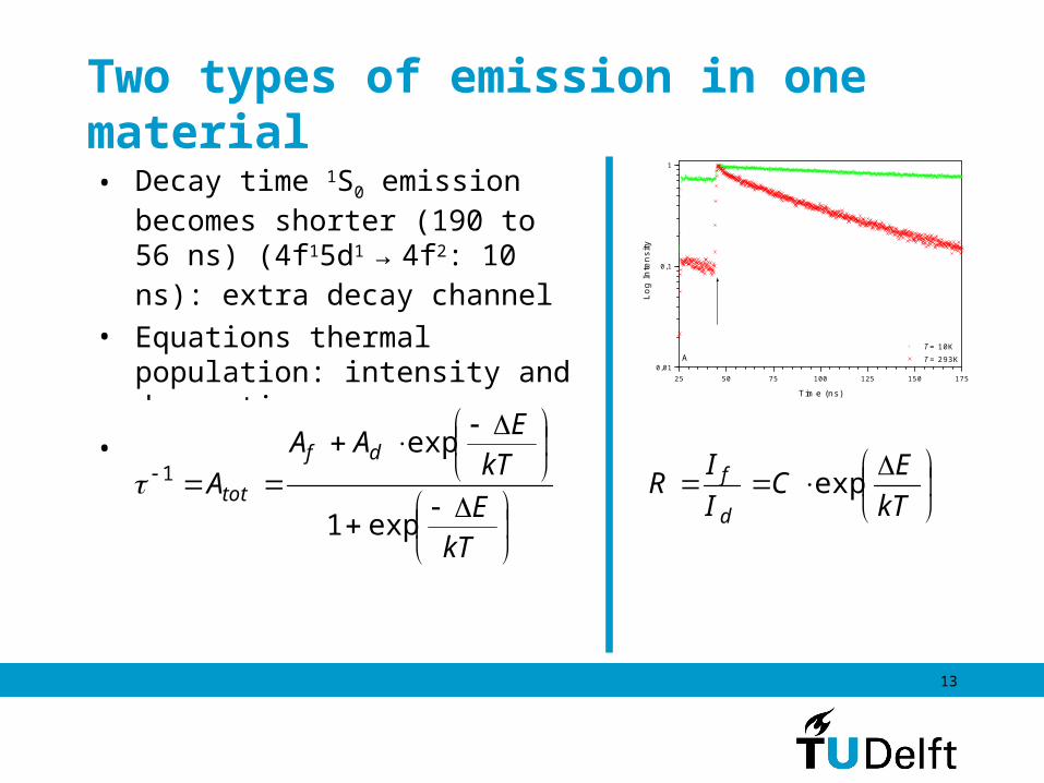
Two types of emission in one material• Decay time 1S0 emission
becomes shorter (190 to 56 ns) (4f15d1
→ 4f2: 10 ns): extra decay channel
• Equations thermal population: intensity and decay time
• Determine energy barrier
25 50 75 100 125 150 1750,01
0,1
1
A T= 10K T= 293K
Lo
g In
ten
sity
Time (ns)
kTE
CII
Rd
f exp
kTEkT
EAA
Adf
tot
exp
exp
1
1

14
Two types of emission in one material• Results on intensity
measurements straightforward• Lifetime measurements: fitting
Af=6.24*106 s-1, Ad=62.24*106 s-1 (16 ns)
• Determining ΔE: 0.041 eV (intensity) and 0.040 eV (decay time)
• ΔE: energy barrier, not ΔE (1S0, 4f15d1)!
0,012 0,010 0,008 0,006 0,004 0,0020
-1
-2
-3
-4 Data points (
exc=188 nm)
Data points (exc
=205 nm) Linear fit: ln(R)=a/T+b
ln (
R)
1/T (K-1)
0 50 100 150 200 250 3000
5
10
15
20
1/
(1
06 s-1)
Temperature (K)

15
Two types of emission in one material• Effect is also found for other
lanthanides with low 4fn-15d1
bands (Eu2+, Sm2+), but not for trivalent lanthanides
E 4f15d
1 (2)
4f15d
1 (1)
1S0
Q

16
Quantum cutting with X Rays
• Ce3+ [Xe] 4f1 configuration• Excitation over the band gap:
direct recombination and Self Trapped Exciton (STE) formation
• Both emissions give the same 4f05d1 emission to 2F7/2,2F5/2
• Scintillator applications: STE formation is unwanted; makes the scintillator slower
• Increase of temperature: more Ce3+ emission, less STE
• Increase of Ce3+ concentration, less STE: more efficient transfer 0
10
20
30
404f05d1
2F7/2
2F5/2
Ene
rgy
(103 cm
-1)

17
Quantum cutting with X Rays
• Pr3+ [Xe] 4f1 configuration• Excitation over the band gap:
direct recombination and STE formation
• Band gap can be reached with X rays and VUV (λexc=111 nm)
• SrAlF5:Pr3+ at low temperatures
200 300 400 500 6000.0
0.2
0.4
0.6
0.8
1.0
X r
ay e
xcita
tion
T=
100K
exc
=11
1 nm
T=
10K
Inte
nsity
(a.
u.)
Wavelength (nm)

18
Quantum cutting with X Rays
• SrAl12O19:Pr3+ material: quantum cutter
• Concentration dependence of STE emission! (a: 0.05 %, b: 0.1 %, c: 0.5% and d: 1.0 %)
• At room temperature 1S0
emission is present: PCE process

19
Quantum cutting with X Rays
• Two processes: direct recombination (PCE) and formation of STE transferring its energy to Pr3+
• Studied SrAlF5:Pr3+ under X ray excitation
• STE: 260-545 nm
• < 403 nm 1S0 emissions
• > 487 nm 3P0 and 1D2 emissions
• STE does not overlap with 1S0 level (~215 nm)
200 300 400 500 600 700 800
0.00
0.08
0.16
0.24
0.32
0.40 T=100K T=350K
Inte
nsity
(*1
E9)
Wavelength (nm)
0
10
20
30
40
50
60
4f15d1
3F3,3F
43H
6,3F
2
1G4
1D2
3P0
3P2
3P1,1I
6
1S0
3H53H4
Ene
rgy
(103 cm
-1)

20
Quantum cutting with X Rays
• 3P0 and 1D2 are fed by both STE energy transfer and second step PCE process: quench from 300K
• Is the energy transfer STE-Pr3+ efficient?
• Measurements on NaMgF3:Pr3+ at room temperature
100 150 200 250 300 350
0.0
0.1
0.2
0.3
0.4
0.5
1S0->1I
6
3P0->3H
4
1D2->3H
4
STE
Inte
nsi
ty
Temperature (K)
200 300 400 500 600 7000.0
0.2
0.4
0.6
0.8
1.0 exc
=190 nm
exc
= 90 nm
3P0 3H
6
3P0 3H
5
1D2 3H
41S
0 3F
3
1S0 1G
4
1S0 1D
2
1S0 3H
4
3P0 3H
4
1S0 1I
6
Inte
nsity
(a.
u.)
Wavelength (nm)

21
Quantum cutting with X Rays
90
75
60
45
30
15
0
3 eV
11 eV
Pr3+
CB
VB
En
erg
y (1
03 cm
-1)
STE
4f15d1
3F3,3F
4
3H6,3F
2
1G4
1D2
3PJ (J:0,1,2), 1I
6
1S0
3H5
3H4

22
Quantum cutting with X Rays
• Direct recombination is dependent on temperature: rate determining step
• Which sequence? • First Pr3+ + h+→Pr4+ then Pr4+ +
e-→Pr3+ (4f15d1)• First Pr3+ + e-→Pr2+ then Pr2+ +
VK→Pr3+ (4f15d1)• Measured Intensity (1S0→1I6) as
function of temperature for SrAlF5:Pr3+
• Arrhenius behavior: lnI versus 1/T
• Analysis: ΔE= 0.06 eV, 455 cm-
1, 2.2kT (RT)
0.0025 0.0030 0.0035 0.0040 0.0045 0.0050 0.0055 0.0060-3.2
-2.8
-2.4
-2.0
-1.6
-1.2
-0.8 Data point Least squares fit
Ln
I
1/T (K-1)
kTE
CI exp*

23
Quantum cutting with X Rays
• Energy value is small, a typical value for a shallow electron trap, too small for a VK center
• So: first Pr3+ + h+→Pr4+ then Pr4+ + e-→Pr3+ (4f15d1)
• PCE process is determined by the recombination rate of electron trap with Pr4+
3a
6electron trap
7b
7a
4
5a
5b
3b
2b
2a
1
90
75
60
45
30
15
0
Pr3+
CB
VB
Ene
rgy
(103 c
m-1)
STE
4f15d1
3F3,3F
4
3H6,3F
2
1G4
1D2
3PJ (J:0,1,2), 1I
6
1S0
3H5
3H4

24
Energy transfer 1S0 emission
• 1S0 → 1I6 (400 nm, UV)
emission step not suitable for lamp applications
• Possible solution: co-doping with other lanthanides or with transition metal ions
• Possible candidate: Mn2+ (3d5): 1S0 → 1I6 overlaps with 6A1 →4A1, 4E (around 400 nm)
0
10
20
30
40
50
60
Mn2+Pr3+
4T24T14A2
4T14E
4T2
4A1,
2E
4T2
6A1
4T1
4f15d
1
3F3,
3F4
3H6,
3F2
1G4
1D2
3P0
3P2
3P1,
1I6
1S0
3H5
3H4
Ene
rgy
(103 cm
-1)

25
Energy transfer 1S0 emission
• SrAlF5:Mn2+ and SrAlF5:Pr3+,Mn2+ (excitation into Pr3+ at 190 nm)
• No Mn2+ emission visible• X Ray excitation: Mn2+ built in!
200 300 400 500 600 700 8000,0
0,5
1,0
1,5
2,0
2,5
3,0
3,5
4,0
4,5
scaled
SrAlF5:Pr
3+,Mn
2+
SrAlF5:Pr
3+
SrAlF5:Mn
2+
Inte
nsi
ty (
*1E
9)
Wavelength (nm)
50 150 250 350 450 550 650 7500,0
0,2
0,4
0,6
0,8
1,0
Mn2+
STE
em
=523 nm exc
=113 nm
Inte
nsi
ty (
a.u
.)
Wavelength (nm)
250 300 350 400 450 500 550 600 650 700
0,0
0,2
0,4
0,6
0,8
1,0
second orderInte
nsi
ty (
a.u
.)
Wavelength (nm)

26
Conclusions
• Discussed quantum cutting for Pr3+ in a large number of hosts
• Can predict properties Pr3+ from Ce3+ data (scintillation)• Pr3+ in some hosts can show both 4f15d1 emission and 4f2
emission from the same spectroscopic site• Excitation with X Rays can also result in quantum cutting,
but is temperature dependent• Fluoride materials are the most promising materials, have
to be co-doped with another ion• Energy transfer Pr3+-Mn2+ not visible up till now