1 Purpose and Scope 2 Table of Contents Welding and Brazing Workmanship Requirements ..... 6 6...
40
ViaSat, Inc. Process Area: Document Number: Revision: Quality 070-QA-044 05 Name of Document: Process Category: Page: Standard for Workmanship and General Practices Quality 1 of 40 ViaSat Proprietary 1 Purpose and Scope To establish procedures and ensure consistency in requirements for general workmanship and standard practices of electronics hardware. The documents referenced herein shall represent the minimum workmanship standards for all fabricated printed circuit boards, electronic sub-assemblies and assemblies, as well as mechanical assemblies, which represent ViaSat products. The requirements herein are applicable not only to ViaSat and its Divisions but all contracted product for which this standard would be imposed. 2 Table of Contents 1 Purpose and Scope ................................................................................................................... 1 2 Table of Contents..................................................................................................................... 1 3 General Procedure ................................................................................................................... 1 4 Metal Fabrication Workmanship Requirements ...................................................................... 3 5 Welding and Brazing Workmanship Requirements ................................................................ 6 6 Mechanical Assemblies ........................................................................................................... 7 7 Cleaning of Parts and Assemblies ........................................................................................... 8 8 Wiring/Cable Crimping and Installation Workmanship .......................................................... 9 9 Acceptance Criteria for Circular Coax Crimps ..................................................................... 12 10 Handling of Equipment ...................................................................................................... 16 11 Cosmetic Inspection Criteria.............................................................................................. 16 11.1 Purpose and Scope ..................................................................................................... 16 11.2 Inspection Purpose ..................................................................................................... 16 11.3 Terms and Defect Definitions ..................................................................................... 16 11.4 Preferred Appearance Quality ................................................................................... 33 11.5 Surface Categories ..................................................................................................... 34 11.6 Light Source................................................................................................................ 34 11.7 Inspection Table Surface ............................................................................................ 34 11.8 Viewing Time .............................................................................................................. 35 11.9 Viewing Orientation ................................................................................................... 35 11.10 Magnification Tools.................................................................................................... 35 11.11 Viewing Distance ........................................................................................................ 35 11.12 Acceptable Defects Matrix.......................................................................................... 36 12 References .......................................................................................................................... 40 3 General Procedure Verify all workmanship attributes comply with drawing specifications as well as the appropriate reference standard Workmanship
Transcript of 1 Purpose and Scope 2 Table of Contents Welding and Brazing Workmanship Requirements ..... 6 6...

ViaSat, Inc. Process Area: Document Number: Revision:
Quality 070-QA-044 05
Name of Document: Process Category: Page:
Standard for Workmanship and General Practices Quality 1 of 40
ViaSat Proprietary
1 Purpose and Scope
To establish procedures and ensure consistency in requirements for general workmanship and standard practices of
electronics hardware.
The documents referenced herein shall represent the minimum workmanship standards for all fabricated printed
circuit boards, electronic sub-assemblies and assemblies, as well as mechanical assemblies, which represent ViaSat
products. The requirements herein are applicable not only to ViaSat and its Divisions but all contracted product for
which this standard would be imposed.
2 Table of Contents
1 Purpose and Scope ................................................................................................................... 1 2 Table of Contents..................................................................................................................... 1 3 General Procedure ................................................................................................................... 1 4 Metal Fabrication Workmanship Requirements ...................................................................... 3
5 Welding and Brazing Workmanship Requirements ................................................................ 6 6 Mechanical Assemblies ........................................................................................................... 7
7 Cleaning of Parts and Assemblies ........................................................................................... 8 8 Wiring/Cable Crimping and Installation Workmanship .......................................................... 9 9 Acceptance Criteria for Circular Coax Crimps ..................................................................... 12
10 Handling of Equipment ...................................................................................................... 16 11 Cosmetic Inspection Criteria.............................................................................................. 16
11.1 Purpose and Scope ..................................................................................................... 16
11.2 Inspection Purpose ..................................................................................................... 16
11.3 Terms and Defect Definitions ..................................................................................... 16
11.4 Preferred Appearance Quality ................................................................................... 33
11.5 Surface Categories ..................................................................................................... 34
11.6 Light Source ................................................................................................................ 34
11.7 Inspection Table Surface ............................................................................................ 34
11.8 Viewing Time .............................................................................................................. 35
11.9 Viewing Orientation ................................................................................................... 35
11.10 Magnification Tools .................................................................................................... 35
11.11 Viewing Distance ........................................................................................................ 35
11.12 Acceptable Defects Matrix .......................................................................................... 36
12 References .......................................................................................................................... 40
3 General Procedure
Verify all workmanship attributes comply with drawing specifications as well as the appropriate reference standard
Workmanship

Name of Document: Document Number: Revision Page:
Standard for Workmanship and General Practices 070-QA-044 05 2 of 40
ViaSat Proprietary
All procedures applied in the manufacture of products as referenced in Section 4 are expected to be in accordance
with the best manufacturing practices that will produce the highest quality products. ViaSat, Inc. or any Divisions,
as the Buyer, reserves the right to review all Supplier procedures on workmanship practices during a process audit
under the AS9100 / ISO 9001 Quality Management System or any additional or subsequent systems that ViaSat, Inc.
may deem necessary to impose. Those procedures should detail or reference practices such as:
soldering practices as specified in IPC documents
marking of parts and assemblies
wiring assembly and installation practices
welding and brazing practices
plating practices
riveting practices
surface finishing practices (e.g., faying, sealing, painting, sanding, conformal coating, passivation, etc.)
machining operations practices
screw assembly practices
deburring practices
sharp edges removal practices
proper removal of unwanted contaminates and surface films
The Supplier shall schedule and perform inspections on the contracted product throughout the manufacturing
process to insure compliance with approved procedures for workmanship practices. Examples of areas to be
inspected are:
mounting and installing parts and subassemblies
cleaning of parts and assemblies
installation of threaded fasteners and rivets
installation of gear and bearing assemblies
assembly of wiring
installation of wiring
soldering, welding and brazing
The Supplier should develop inspection checklists so that consistent inspections can be conducted to insure good
workmanship.
Name of Document: Document Number: Revision Page:
Standard for Workmanship and General Practices 070-QA-044 05 3 of 40
ViaSat Proprietary
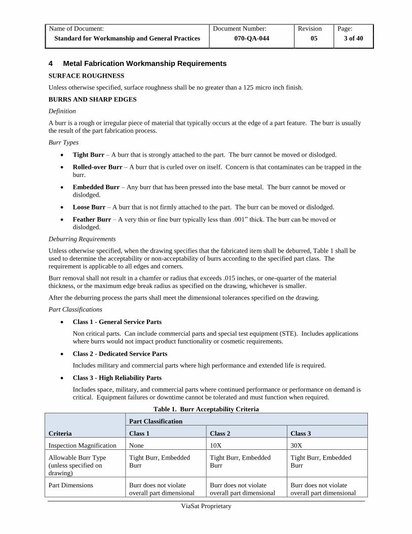
4 Metal Fabrication Workmanship Requirements
SURFACE ROUGHNESS
Unless otherwise specified, surface roughness shall be no greater than a 125 micro inch finish.
BURRS AND SHARP EDGES
Definition
A burr is a rough or irregular piece of material that typically occurs at the edge of a part feature. The burr is usually
the result of the part fabrication process.
Burr Types
Tight Burr – A burr that is strongly attached to the part. The burr cannot be moved or dislodged.
Rolled-over Burr – A burr that is curled over on itself. Concern is that contaminates can be trapped in the
burr.
Embedded Burr – Any burr that has been pressed into the base metal. The burr cannot be moved or
dislodged.
Loose Burr – A burr that is not firmly attached to the part. The burr can be moved or dislodged.
Feather Burr – A very thin or fine burr typically less than .001” thick. The burr can be moved or
dislodged.
Deburring Requirements
Unless otherwise specified, when the drawing specifies that the fabricated item shall be deburred, Table 1 shall be
used to determine the acceptability or non-acceptability of burrs according to the specified part class. The
requirement is applicable to all edges and corners.
Burr removal shall not result in a chamfer or radius that exceeds .015 inches, or one-quarter of the material
thickness, or the maximum edge break radius as specified on the drawing, whichever is smaller.
After the deburring process the parts shall meet the dimensional tolerances specified on the drawing.
Part Classifications
Class 1 - General Service Parts
Non critical parts. Can include commercial parts and special test equipment (STE). Includes applications
where burrs would not impact product functionality or cosmetic requirements.
Class 2 - Dedicated Service Parts
Includes military and commercial parts where high performance and extended life is required.
Class 3 - High Reliability Parts
Includes space, military, and commercial parts where continued performance or performance on demand is
critical. Equipment failures or downtime cannot be tolerated and must function when required.
Table 1. Burr Acceptability Criteria
Criteria
Part Classification
Class 1 Class 2 Class 3
Inspection Magnification None 10X 30X
Allowable Burr Type
(unless specified on
drawing)
Tight Burr, Embedded
Burr
Tight Burr, Embedded
Burr
Tight Burr, Embedded
Burr
Part Dimensions Burr does not violate
overall part dimensional
Burr does not violate
overall part dimensional
Burr does not violate
overall part dimensional
Name of Document: Document Number: Revision Page:
Standard for Workmanship and General Practices 070-QA-044 05 4 of 40
ViaSat Proprietary
Criteria
Part Classification
Class 1 Class 2 Class 3
requirements requirements
requirements
Part Function Does not affect part form
or function as determined
by engineering.
Does not affect part form
or function as determined
by engineering.
Does not affect part form
or function as determined
by engineering.
Acceptable Burr Locations Non-critical areas of part
as determined by
engineering.
Non-critical areas of part
as determined by
engineering.
Non-critical areas of part
as determined by
engineering.
Burr Attachment
Condition
Not removable by hand or
tweezers.
Not removable by hand or
tweezers.
Not removable by hand or
tweezers.
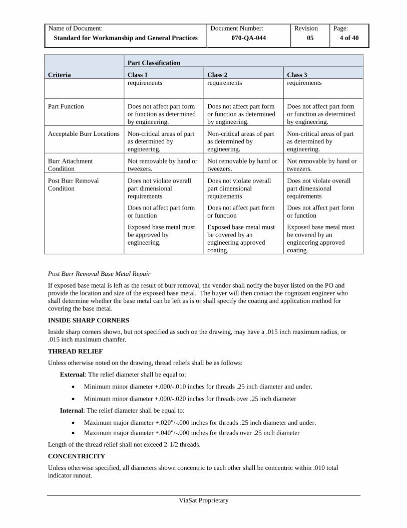
Post Burr Removal
Condition
Does not violate overall
part dimensional
requirements
Does not affect part form
or function
Exposed base metal must
be approved by
engineering.
Does not violate overall
part dimensional
requirements
Does not affect part form
or function
Exposed base metal must
be covered by an
engineering approved
coating.
Does not violate overall
part dimensional
requirements
Does not affect part form
or function
Exposed base metal must
be covered by an
engineering approved
coating.
Post Burr Removal Base Metal Repair
If exposed base metal is left as the result of burr removal, the vendor shall notify the buyer listed on the PO and
provide the location and size of the exposed base metal. The buyer will then contact the cognizant engineer who
shall determine whether the base metal can be left as is or shall specify the coating and application method for
covering the base metal.
INSIDE SHARP CORNERS
Inside sharp corners shown, but not specified as such on the drawing, may have a .015 inch maximum radius, or
.015 inch maximum chamfer.
THREAD RELIEF
Unless otherwise noted on the drawing, thread reliefs shall be as follows:
External: The relief diameter shall be equal to:
Minimum minor diameter +.000/-.010 inches for threads .25 inch diameter and under.
Minimum minor diameter +.000/-.020 inches for threads over .25 inch diameter
Internal: The relief diameter shall be equal to:
Maximum major diameter +.020"/-.000 inches for threads .25 inch diameter and under.
Maximum major diameter +.040"/-.000 inches for threads over .25 inch diameter
Length of the thread relief shall not exceed 2-1/2 threads.
CONCENTRICITY
Unless otherwise specified, all diameters shown concentric to each other shall be concentric within .010 total
indicator runout.
Name of Document: Document Number: Revision Page:
Standard for Workmanship and General Practices 070-QA-044 05 5 of 40
ViaSat Proprietary
PERPENDICULARITY OF HOLES
Unless otherwise specified, clearance holes shown perpendicular to a surface shall be perpendicular within 0.5
degrees. Unless otherwise specified, tapped holes shown perpendicular to a surface shall be perpendicular within 1.0
degree.
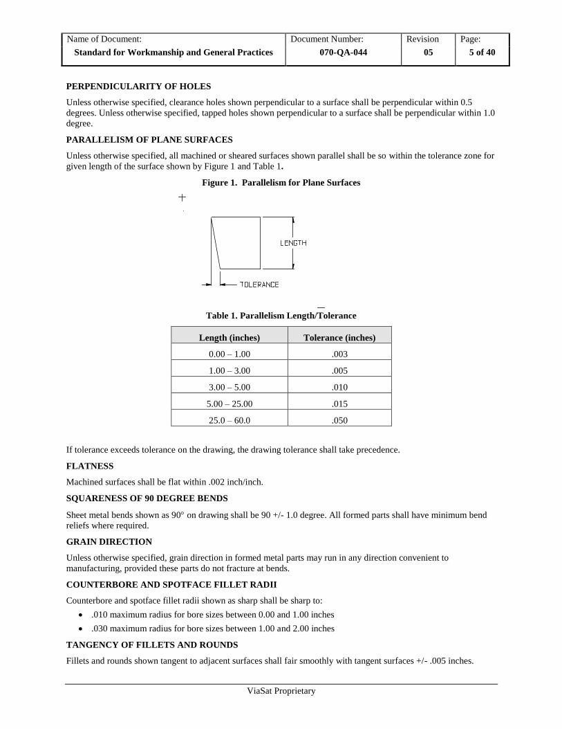
PARALLELISM OF PLANE SURFACES
Unless otherwise specified, all machined or sheared surfaces shown parallel shall be so within the tolerance zone for
given length of the surface shown by Figure 1 and Table 1.
Figure 1. Parallelism for Plane Surfaces
Table 1. Parallelism Length/Tolerance
Length (inches) Tolerance (inches)
0.00 – 1.00 .003
1.00 – 3.00 .005
3.00 – 5.00 .010
5.00 – 25.00 .015
25.0 – 60.0 .050
If tolerance exceeds tolerance on the drawing, the drawing tolerance shall take precedence.
FLATNESS
Machined surfaces shall be flat within .002 inch/inch.
SQUARENESS OF 90 DEGREE BENDS
Sheet metal bends shown as 90 on drawing shall be 90 +/- 1.0 degree. All formed parts shall have minimum bend
reliefs where required.
GRAIN DIRECTION
Unless otherwise specified, grain direction in formed metal parts may run in any direction convenient to
manufacturing, provided these parts do not fracture at bends.
COUNTERBORE AND SPOTFACE FILLET RADII
Counterbore and spotface fillet radii shown as sharp shall be sharp to:
.010 maximum radius for bore sizes between 0.00 and 1.00 inches
.030 maximum radius for bore sizes between 1.00 and 2.00 inches
TANGENCY OF FILLETS AND ROUNDS
Fillets and rounds shown tangent to adjacent surfaces shall fair smoothly with tangent surfaces +/- .005 inches.

Name of Document: Document Number: Revision Page:
Standard for Workmanship and General Practices 070-QA-044 05 6 of 40
ViaSat Proprietary
5 Welding and Brazing Workmanship Requirements
Aluminum Brazing
ViaSat brazing procedure specifications
When the class of braze is not specified on the ViaSat drawing, or other applicable document, Class A
requirements shall apply per AWS 3.7M/C3.7:2011.
Filler material shall be compatible to the material being brazed.
Brazing filler material will be AWS A5.8m/A5.8 approved foil or paste as specified on the drawing.
Fluxes shall conform to AWS A5.3M/A5.31and shall be compatible to filler material and shall remove oxides to
prevent their reformation during the braze process.
Controlled Atmosphere Brazing (CAB)
Assemblies will be cleaned and assembled following a documented procedure with traceability to each braze run
and will include.
Thermocouple placement and quantity
Thermal Profiles
Cooling time
Welding
When not specified on the drawing ViaSat welded assemblies will be based on the best practices identified in AWS
D17.1/D17.1M:2010-AMD1.
Parts must be checked and verified that they are to print, before welding. Once welding begins selective welding
techniques must be exercised, so that surface distortion is held to a minimum.
BUTT WELDS
Unless otherwise specified, all butt weld joints shall have complete penetration.
WELD SIZES
Fillet weld sizes shall be at least 140% of the thickness of the thinner material unless specified otherwise.
JOINT APPEARANCE
Welds shall be free from harmful defects (e.g., cracks, porosity, undercuts, voids, and gaps). All welds and brazes
shall show no burn-through. Weld bead appearance, cross-section and ripples shall be uniform and smooth.
GRINDING
Grinding shall affect the minimum area possible to satisfy the drawing requirements. Welds shall not be ground
unless required by drawing.

Name of Document: Document Number: Revision Page:
Standard for Workmanship and General Practices 070-QA-044 05 7 of 40
ViaSat Proprietary
6 Mechanical Assemblies
6.1 When mounting and installing parts and/or subassemblies, the following practices will be adhered to wherever
applicable:
Assembled parts and hardware should be secured or mounted in a manner that satisfactorily accomplishes
the intended purpose without degrading or becoming damaged in the environment in which they are to be
used.
Electronic equipment comprised of missing, inoperative, defective, bent, broken, or otherwise damaged
parts will be deemed unacceptable.
Parts (e.g., hinges, catches, handles, knobs, etc.) installation should avoid damaging adjacent hardware or
the mounting surface.
Rework to damaged finishes will be considered successfully performed when the surfaces are touched-up
with a continuous protective coating of identical composition as the original coating material.
The touch-up color should match the original finish such that the blended colors are not visually noticeable.
6.2 Installation of Threaded Fasteners and Rivets
Threaded fasteners and rivets should be carefully selected and applied so as to produce a safe, non-corroding,
functional and long-lived joining of materials. Commonly practiced procedures, guidelines and requirements
are:
Screws, nuts and bolts should show no evidence of cross threading, mutilation, or detrimental or
hazardous burrs.
The mixing of fasteners composed of different metals should be strictly controlled (e.g., steel nuts against
aluminum flat washers) because dissimilar metals encourage corrosion and unequal resistance to
mechanical stresses. Exceptions would include breakaway applications.
Uneven/over stresses between soft and hard materials should be avoided because such stresses cause
unwanted fatigue or early failure (e.g., steel screws fastening plastic pieces, aluminum screws to stainless
steel nuts, etc.).
All screw-type fasteners should be tight. Tight is defined as the screw or rivet being firmly secured with
no noticeable movement between the attached parts before or after applying maximum force by hand
without tools. It should be noted that tight may not guarantee unloosening, over time, due to vibration and
movement between joined metals.
In critical applications or whenever tightening of fasteners is insufficient, the Supplier manufacturing
processes should specify the proper torque requirements for threaded fasteners.
Self-locking fasteners and lock-wiring will be acceptable when specified on the engineering drawing.
Split-ring lock washers may be used if buffered by flat washers when specified on the engineering
drawing.
Star lock washers will not be allowed.
Anti-seizing chemical locking agents (e.g., Loctite) may be used and only sparingly, with the exception of
instances when grounding bonds of less than 0.10 Ohm are required as specified on the engineering
drawing.
The riveting operation should be carefully performed such that the rivets are tight and satisfactorily
headed with the rivet heads tightly seated against their bearing surface.

Name of Document: Document Number: Revision Page:
Standard for Workmanship and General Practices 070-QA-044 05 8 of 40
ViaSat Proprietary
7 Cleaning of Parts and Assemblies
The proper methods for cleaning parts and assemblies during the fabrication of product are essential in assuring the
expected performance and long operational life. The subsequent procedures are offered as examples of acceptable
cleanliness practices.
Product shall be cleaned of:
loose, spattered or excess solder
weld metal
metal chips
mold release agents
smudges
any other foreign material which might detract from the intended operation, function, or acceptable
appearance of the product
unwanted particles that could loosen or become dislodged during the normal expected life of the product
all corrosive material prior to parts assembly into the product
contaminants (e.g., lubricating oils, mold release agents, waxes, sand, corrosion products, solder fluxes,
finger prints, dust, etc.)
all contaminants without incurring damage or change of electrical and mechanical properties of the product
by using the safest and most appropriate agent and methods
After cleaning, the product should be allowed to dry. Any remaining loose contaminants should be blown or
vacuumed away, and all moving parts and assemblies should be relubricated according to design requirements. In
addition, post inspection should reveal no damage, unusual wear or presence of contamination on the product.
Name of Document: Document Number: Revision Page:
Standard for Workmanship and General Practices 070-QA-044 05 9 of 40
ViaSat Proprietary
8 Wiring/Cable Crimping and Installation Workmanship
Requirements
ViaSat and all ViaSat Subcontractors or Suppliers performing wiring/cable crimping operations shall implement the
following steps to ensure proper tooling is used and maintained, resulting in acceptable connector contact crimps:
1. Tooling and assembly procedures for wiring shall be per Manufacturers' instructions unless otherwise specified
herein.
2. ViaSat Manufacturing Engineering & Quality Engineering shall review the cable assembly drawings with the
Supplier and discuss the assembly materials, tooling and processes to be utilized to manufacture acceptable
wiring/cable assemblies.
3. All BOM items shall be reviewed. Extra contact pins shall be required to develop the wiring or cable assembly
process and perform the necessary tooling verification tests prior to assembly of production units.
4. Each contact or pin to be crimped shall require specific tooling and this shall be reviewed with the cable
manufacturer.
5. All crimp tooling shall be uniquely and permanently identified with a part number and serial number (e.g., S/N
1, 2, 3) and shall be under the calibration control program of the cable manufacturer. As such, a sticker shall be
added to each tool stating the calibration interval. Note: In the case of crimpers that use exchangeable die sets,
the handles and dies shall each individually be serialized and controlled.
6. The proper wiring/cable preparation and crimping process shall be contained in adequate instructions and
referenced in assembly drawings or other appropriate assembly documentation.
7. The visual acceptance criteria for circular coaxial connector contact crimps (which is not covered by IPC
documentation) shall be discussed, and reviewed against the ViaSat acceptance criteria procedure (see
Reference Documents section.)
8. First Articles of contact crimps, and a detailed first article inspection (FAI) report shall be provided to ViaSat
by the wiring/cable manufacturer as required by contract. The First Articles shall be presented to ViaSat for
approval such that the cable crimps can be reviewed and inspected without any cable disassembly.
9. In the case of coaxial crimps, a set of go/no-go gauge tools shall be provided by the wiring/cable manufacturer
and used to ensure the dimensions of the coaxial crimp tooling is acceptable for the contacts specified on the
drawing. An optional method to be measurement of completed crimps to specifications by the crimp contact
manufacturer.
10. Operator and Inspector training shall be provided by the wiring/cable manufacturer (both visual and gauge
tooling checks) for acceptable crimps per requirements. It shall record names, dates and type of training
performed. The Manufacturer, in their training, shall instruct each Operator performing any contact crimps that
it is their responsibility to ensure these crimps are acceptable per the specification applicable before handing the
cable assemblies to the next operation.
11. A Crimp Tooling Logbook shall be created for crimp tooling, and shall accommodate logging of results of daily
a) inspection results of crimp tooling, b) gauge tool checks and c) visual inspection results obtained on the first
three (3) production contact crimps produced with the tooling.
12. At the start of each day’s production of assembly wiring/cables, Manufacturing or Quality personnel shall
inspect the following and log in the Crimp Tooling Logbook:
a. The condition of the crimp tooling. The wear conditions shall be noted, along with any other visual
abnormalities noted.
b. Results of the gauge tool check or measurement in the case of coaxial crimp tooling.
c. The first three (3) production crimps produced with a tool shall be inspected for acceptance per specified
criteria, and results noted.
If acceptable, the tooling shall be released for use for the day for production crimping.
If, however, any contact crimps fail inspection, then production use with this tool shall be withheld until
a failure investigation is completed. The Manufacturer may swap out another qualified and released
tool/die set for production use, provided the successful daily check of that replacement tool is noted in
the Crimp Tooling Logbook. The cause of the rejects shall be identified, and logged in the crimp-
tooling logbook.

Name of Document: Document Number: Revision Page:
Standard for Workmanship and General Practices 070-QA-044 05 10 of 40
ViaSat Proprietary
If the failed crimps are determined to be the result of operator error it shall be recorded in the
logbook. The tooling shall then be closely inspected under magnification to ensure the operator did
not damage it during the crimping of the previous 3 units. In the case of coaxial crimps, an
additional check shall be done with either the go/no-go gauge of the tool or measurement of the
final crimped contact to verify acceptable dimensions. Results of these checks shall be logged. To
verify that it was indeed operator error, the operator shall repeat the crimping operation on another
three (3) production crimps. If there are no visual failures, then the tooling can be released for
daily production use.
If the failure analysis determines the crimp failures to be due to crimp tooling wear or malfunction,
then the tooling shall not be released for production use. Again, this shall be noted in the tooling
logbook.
Any tooling that fails inspection, or gauge tool or measurement checks, must be repaired or
replaced prior to use in production. Sufficient evidence of repair or replacement shall be available.
13. During production, each Operator shall be responsible for the quality of the contact crimps they produce.
Verification of tooling to the Contact Manufacturer specification shall be completed prior to use. ViaSat
encourages use of a “buddy system” whereby an Assembler performs a crimp, then performs a self-check to
ensure the crimp is satisfactory before moving material to the next operation. The next Assembler in the
process flow would then perform a quick check to ensure contacts are crimped properly and may now be
processed through the next assembly sequence.
14. In-process Inspection shall be performed on contact crimps prior to any higher-level or subsequent assembly
steps that may obscure full view of the crimps. Final Inspection shall be performed on the completed cable
assemblies. All results shall be recorded and maintained per the manufacturer’s Quality Management System
documentation as appropriate.
15. All assembly, tooling logbook entries and production/inspection data shall be subject to ViaSat (or ViaSat’s
Subcontractor) review and acceptance.
When installing wiring within an enclosure, the following practices shall be adhered to wherever applicable:
a. Insulated wire running between equipment or subassemblies within one piece of equipment (e.g., between
drawers or chassis and module subassemblies) should be formed into cables or ducted wherever possible.
b. Wire and wire bundles routed through holes in paneling or enclosure walls should be protected with
suitable insulated material (e.g., hole grommets).
c. Wires and cables should be positioned or protected to avoid contact with rough or irregular surfaces and
sharp edges.
d. Wire dress or bundling of wires should not result in improper electrical operation or interference with
mechanical operation that could lead to subsequent damage of the wire or cable.
e. Wiring/wire bundles should be securely supported and carefully routed to minimize chafing and abrasion,
small bend radii (no less than three times the wire or bundle diameter) riding against sharp edges and hard
surfaces, loosing of wire bundles, and occurrence of hotspots at the middle of wire bundles.
f. Riding conditions between wire/wire bundles on hard, sharp edges or surfaces shall be deemed
unacceptable.
g. Cold-flowing characteristics of installed wiring should always be known, understood and be taken into
account when implementing wire routing and bundling schemes.
h. Lacing of cabling should be applied firmly, yet not with excessive pressure such that it could cut into
conductor insulation (e.g., plastic cable ties and “stitch-lock” type lacing tape are acceptable materials for
lacing), as well as be neat and orderly in appearance.
i. Cable or wiring harnesses should be anchored to avoid damage to conductors or adjacent parts.
j. Wire bundles and cables should always be fixed such that there is minimum or no mechanical stresses
(radial, torsional or lateral stresses) at the terminated ends (no wire movement at wire termination points,
e.g., connectors/backshells, contacts, solder and crimp joints, splices, etc.-minimizes the mechanical
stresses).
k. Wire routing should be a safe distance from hot components to eliminate wire insulation deterioration.
l. Generous use of lacing tape, plastic tie-wraps or other non-metallic cable clamps to properly dress and stow
wire bundles will be deemed acceptable practice.
Name of Document: Document Number: Revision Page:
Standard for Workmanship and General Practices 070-QA-044 05 11 of 40
ViaSat Proprietary
m. Insulation should show no evidence of burns, abrading, or pinch marks that could cause short circuits or
current leakage. In addition, any condition or stress that exceeds the voltage withstanding or insulation
resistance characteristics should be eliminated.
n. Wires in a continuous run between two terminals should not be spliced during the assembly of the product,
except where a stranded conductor is spliced to a solid conductor and the two are supported at the splice as
allowed by the engineering drawing.
o. Clearance between wires/cables and heat generating parts (e.g., power semiconductors and resistors) should
be such as to avoid deterioration of the wires or cables from the heat dissipated by these parts under the
specified service conditions of the product.
p. Shielding on wires and cables should be secured in a manner that prevents contact or shorting of exposed
current-carrying parts.
q. Shielding should terminate at sufficient distance from the exposed conductors of the cable to prevent
shorting or arcing between the cable conductor and the shielding. The ends of the shielding or braid should
be secured against fraying.

Name of Document: Document Number: Revision Page:
Standard for Workmanship and General Practices 070-QA-044 05 12 of 40
ViaSat Proprietary
9 Acceptance Criteria for Circular Coax Crimps
Circular ferrule crimps are not covered in IPC/WHMA-A-620 and therefore have no acceptance criteria associated
with them. It is the purpose of this document to provide the acceptance and rejection criteria for those circular
ferrule crimps to assist with proper assembly and inspection. Standard inspection methods per IPC/WHMA-A-620
shall be applied for circular ferrule crimps. When applicable, this procedure should be cited on the engineering
drawing as the acceptance criteria. Inspections cited herein are accomplished using a high-powered inspection
scope with at least 10X magnification. Substitute inspection scopes should be used to provide the necessary detail to
detect the assembly defects cited herein.
Note: for coaxial and twin-axial assemblies to function properly, it is critical that all assembly instructions provided
by the manufacturer be followed.
Defects/Rejectable Conditions
Defect: Axial Misalignment (See Figure 1) Deformation (banana) of the contact/terminal that affects form, fit,
function or reliability. This type of deformation may interfere with proper insertion or extraction from connector
assembly.
Figure 1. Axial Misalignment (Banana) of the Crimped Contact
Defect: Ferrule Fractures and Cracks - Contact has visible fractures (See Figure 2) or cracks (See Figure 3) in the
formed ferrule.

Name of Document: Document Number: Revision Page:
Standard for Workmanship and General Practices 070-QA-044 05 13 of 40
ViaSat Proprietary
Figure 2. Fractured Ferrule
Figure 3. Cracked Ferrule

Name of Document: Document Number: Revision Page:
Standard for Workmanship and General Practices 070-QA-044 05 14 of 40
ViaSat Proprietary
Defect: Dislocated Crimp - Crimp extends past crimp barrel out over the cable.
Defect: Lose Crimp - Ferrule and / or connector turns/moves on cable after crimping. This defect indicates the
shield and/or inner contact is not secured which may result in conditions such as disconnected inner contact and/or
unacceptable RF emissions.
Acceptable Conditions
Acceptable: Slight Deformation (See Figure 4) - Slight deformation or irregularity of the metal in crimp ridge area
due to wear and tear of tool. (Considered to be a process indicator.) Tool should be serviced/repaired as soon as this
condition appears in the crimps. No evidence of cracks or fractures under a minimum of 10X magnification.
Figure 4. Slight Deformation in Crimp Ridge Area
Acceptable: Small Gap (See Figure 4) - Very small gap between outer and inner ferrules with no evidence crimp is
loose or will rotate/move in any way.
Acceptable: Uncentered Crimp - Crimp is not centered on crimp area of terminal but does not cause damage to
terminal or fail to hold.

Name of Document: Document Number: Revision Page:
Standard for Workmanship and General Practices 070-QA-044 05 15 of 40
ViaSat Proprietary
Target Condition
Target: No Deformations (See Figure 5 and 6) - Smooth straight crimp with no rough edges or evidence of
cracking or gaps. Part cannot be rotated or moved after crimping,
Figure 5. Smooth Crimp with No Evidence of Gaps or Cracks
Figure 6. Smooth and Straight Crimp

Name of Document: Document Number: Revision Page:
Standard for Workmanship and General Practices 070-QA-044 05 16 of 40
ViaSat Proprietary
10 Handling of Equipment
Proper handling of parts and equipment must be exercised to preclude physical and/or electrical damage such as
cracks, scratches, twists, fractures, etc. and the possibility of hidden damage such as that produced by flexure of
component leads, stressing of solder joints, over tightening of fasteners, electrostatic discharge (ESD), etc. In
process work is often particularly susceptible to such damage and, as such, special precautions that may include
special fixtures, stowage totes, etc. should be considered.
11 Cosmetic Inspection Criteria
11.1 Purpose and Scope
The purpose of this standard is to define and establish acceptance and rejection criteria for surface finish for
incoming and outgoing inspections applicable at Customer, approved Supplier or Subcontractor and ViaSat. The
company uses similar inspection criteria as today’s technology and market leader. ViaSat can meet any surface
finish on request; our finishing standard is common industrial finish described in Surface Categories Section.
Each finishing class stands for special manufacturing and handling processes, which are proportional to the related
costs. Every customer has to decide if a special cosmetic finish is a requirement or “nice to have”. Manufacturing
processes of bare material (e.g. cold rolled steel, pre galvanized steel, extruded parts) as well from machining
processes (e.g. punching, forming, and welding) may leave visible marks at the finished products, which are not
avoidable. Anodized material is more scratch resistant than Alodine material.
This standard applies to Surface Finishes such as Paint, Chemical Conversion Coating (Alodine, Anodize), Plating,
Molding and silk-screening.
11.2 Inspection Purpose
The inspection purpose is to determine any conditions for which the part or system will be rejected. The intent of
inspection is
To ship a part or system that meets the finish standard of this specification.
It is NOT the intent of inspection to find all imperfections on a part or system.
11.3 Terms and Defect Definitions
Accept per approved engineering drawing
Some cosmetic imperfections are not avoidable in certain process and design circumstances. Approved
engineering documents will point this out.
Abrasion
Surface imperfection that doesn’t remove or displace material appears as a scuff or changes to the surface
finish.
Bare Metal
A metal surface that has an intact protective coating but no cosmetic finish.
Base Metal
A bare metal surface on which the protective coating has been compromised.
Bleed Out
A Substance that runs out of seams. Color can vary from brown, dark brown to gray white at plating.
Name of Document: Document Number: Revision Page:
Standard for Workmanship and General Practices 070-QA-044 05 17 of 40
ViaSat Proprietary
Bleeding
Rough and not densely packed dull gray lines at plated material.
Blister
A bubbling in the surface of the finish. Non-adhesion or lack of proper sticking of the coating to the surface
caused by trapped air, gas or moisture.
Blush
Discoloration or change in gloss.
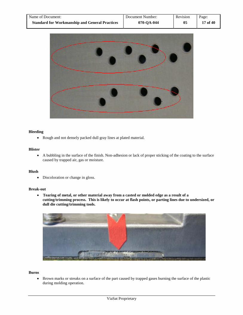
Break-out
Tearing of metal, or other material away from a casted or molded edge as a result of a
cutting/trimming process. This is likely to occur at flash points, or parting lines due to undersized, or
dull die cutting/trimming tools.
Burns
Brown marks or streaks on a surface of the part caused by trapped gases burning the surface of the plastic
during molding operation.

Name of Document: Document Number: Revision Page:
Standard for Workmanship and General Practices 070-QA-044 05 18 of 40
ViaSat Proprietary
Bubble
A bubbling in the surface of the finish. Non-adhesion or lack of proper sticking of the coating to the surface
caused by trapped air, gas or moisture.
Bump
Protrusions caused by trapped air / gas or moisture usually seen in finished parts.
Burnish Marks
Marks or lines that cannot be felt usually caused by tooling dies most common on flattened cold rolled
material e.g. Steel or aluminum sheets
Burrs
Sharp edges around part features caused by manufacturing process like punching, shearing, milling or
drilling.
Caution: Sheet metal edges that are compliant to UL 1439 can still cut through protective gloves and/or
human hands.
Chipping
Areas in which the adhesion between the paint and the surface is poor, causing the paint to come off with
light rubbing.

Name of Document: Document Number: Revision Page:
Standard for Workmanship and General Practices 070-QA-044 05 19 of 40
ViaSat Proprietary
Cloudiness
A haziness or lack of clarity in otherwise transparent part.
Contamination
Rough and not densely packed dull gray lines at plated material. Colored specks of foreign material
embedded in or on the surface part.
Corrosion
Areas of corrosion on any metal surfaces.
Caution: Small areas of rust are acceptable where plating is removed by a standard manufacturing or
welding process, e.g. sheared (cut) edges.
Cracking
Crackled appearance due to poor adhesion usually from surface contamination before plating.
Hairline cracks of anodized material caused by bending, high temperature curing after silk screening of the
aluminum or tool mark hair cracks on the opposite site of the aluminum.
Fine damages which may extend in a pattern on or beneath the surface or through a layer of material.

Name of Document: Document Number: Revision Page:
Standard for Workmanship and General Practices 070-QA-044 05 20 of 40
ViaSat Proprietary
Crazing
A fine mesh of minute cracks on the surface of some plastics due mainly to the effects of UV light.
Delaminating
Separation, peeling of thin layer of material
Dent
A surface depression caused by an impact.
Caution: Tooling marks are not dents.
Die marks
Marks made on the metal’s surface when it is formed, usually consist of long straight lines.
Name of Document: Document Number: Revision Page:
Standard for Workmanship and General Practices 070-QA-044 05 21 of 40
ViaSat Proprietary
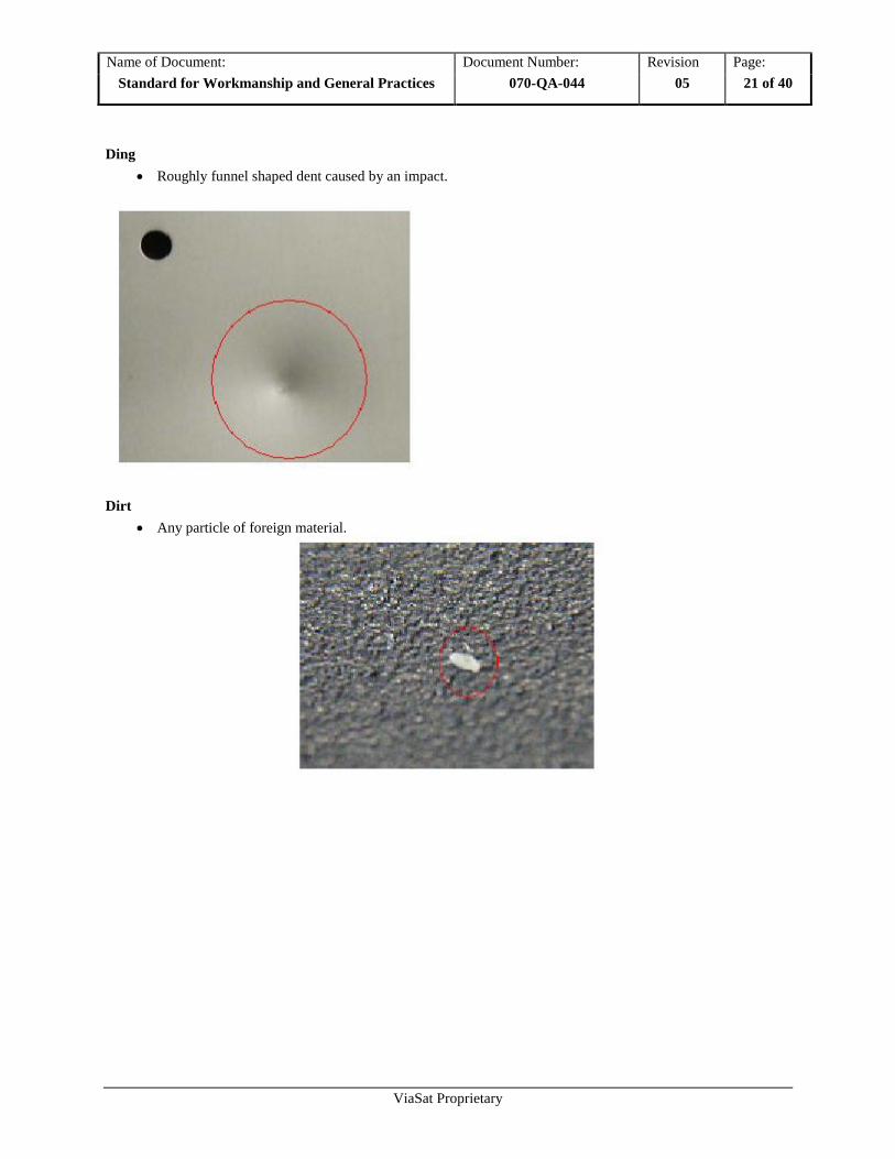
Ding
Roughly funnel shaped dent caused by an impact.
Dirt
Any particle of foreign material.

Name of Document: Document Number: Revision Page:
Standard for Workmanship and General Practices 070-QA-044 05 22 of 40
ViaSat Proprietary
Discoloration
Any change from the original color or shade in the finish.
Distortion
A deformation of a diecasted part

Name of Document: Document Number: Revision Page:
Standard for Workmanship and General Practices 070-QA-044 05 23 of 40
ViaSat Proprietary
Dust
Small particles.
Fill In
An excess of ink that alters the form of a screened feature not affecting legibility.
Fingerprints
An impression left on the surface due to operator handling.
Finish
An area of smoother finish of molded plastic parts.

Name of Document: Document Number: Revision Page:
Standard for Workmanship and General Practices 070-QA-044 05 24 of 40
ViaSat Proprietary
Flaking
Areas in which the adhesion between the paint and the surface is poor, causing the paint to come off with
light rubbing.
Flash
Thin, excess material usually around the area of the mold parting line or internal shutoff areas.
Flow Marks
Waviness of edge or excess linear surface texture of silk-screened areas.
Fracture
Material splitting usually on the outside bend radius.
Gates
Point at which plastic is injected in cavity, usually on parting line.
Gloss
A uniform appearance of a painted or molded area. E.g. Shiny, matt
Glossiness
An area of either excessive or deficient gloss.
Gouge
A groove or scratch that extends through the finish and into the metal caused by a sharp object. A depth is
measurable.

Name of Document: Document Number: Revision Page:
Standard for Workmanship and General Practices 070-QA-044 05 25 of 40
ViaSat Proprietary
Grease
Any lubricant transferred to the part’s surface, shiny or glossy patches on the surface of the part.
Haze
Cloudiness on an otherwise transparent part.
Inconsistency
Variation of gloss, thickness of line or surface texture.
Inclusions
Small craters on surface caused by dust or dirt.
Lint
Any unintended foreign substance in the coating or on the surface.
Marbling
Colored streaks on a surface caused by improper mixing of molten plastic.
Marks
Pits, sanding, or other marks on base material that remains visible after coating.
Matt Finish
A less glossy finish of a surface area.
Metal Fuzz
Fine grit metal shavings that are clumped together may also be magnetic.
Name of Document: Document Number: Revision Page:
Standard for Workmanship and General Practices 070-QA-044 05 26 of 40
ViaSat Proprietary
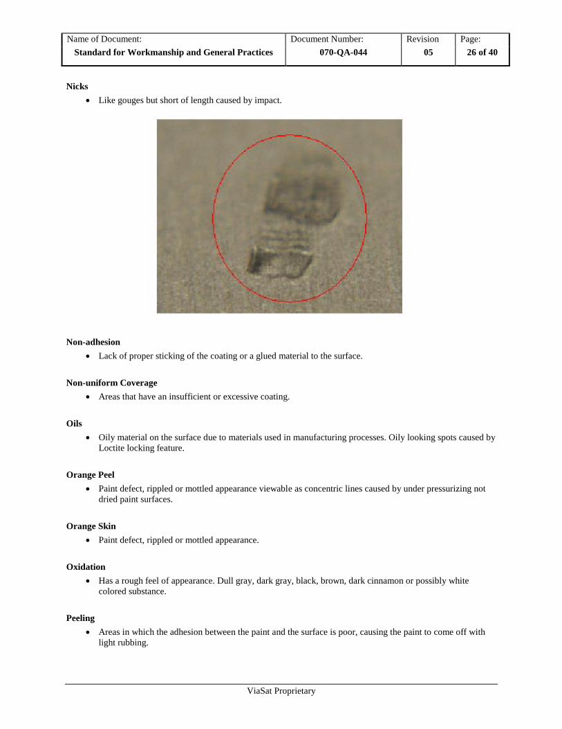
Nicks
Like gouges but short of length caused by impact.
Non-adhesion
Lack of proper sticking of the coating or a glued material to the surface.
Non-uniform Coverage
Areas that have an insufficient or excessive coating.
Oils
Oily material on the surface due to materials used in manufacturing processes. Oily looking spots caused by
Loctite locking feature.
Orange Peel
Paint defect, rippled or mottled appearance viewable as concentric lines caused by under pressurizing not
dried paint surfaces.
Orange Skin
Paint defect, rippled or mottled appearance.
Oxidation
Has a rough feel of appearance. Dull gray, dark gray, black, brown, dark cinnamon or possibly white
colored substance.
Peeling
Areas in which the adhesion between the paint and the surface is poor, causing the paint to come off with
light rubbing.

Name of Document: Document Number: Revision Page:
Standard for Workmanship and General Practices 070-QA-044 05 27 of 40
ViaSat Proprietary
Pitting
Small craters on surface.
Punch mark
Mark on the surface of a material due to punch process.
Runs
Drips, bleeding, visible lines or raised areas of excessive paint or chemical coating similar to non-uniform
coverage.

Name of Document: Document Number: Revision Page:
Standard for Workmanship and General Practices 070-QA-044 05 28 of 40
ViaSat Proprietary
Rust
Areas of corrosion on any metal surfaces
.
Caution: Small areas of rust are acceptable where plating is removed by a standard manufacturing or
welding process, e.g. sheared (cut) edges.
Scratch
A shallow groove that can be seen but not felt.
Scuff marks
A series of very light, concentrated scratches that can be seen but not felt.
Short-Shot
Incomplete molded feature.
Name of Document: Document Number: Revision Page:
Standard for Workmanship and General Practices 070-QA-044 05 29 of 40
ViaSat Proprietary
Sink
Depression or dimple caused by non-uniform material shrinkage.
Slug Mark
A surface deformity caused by the punching process.
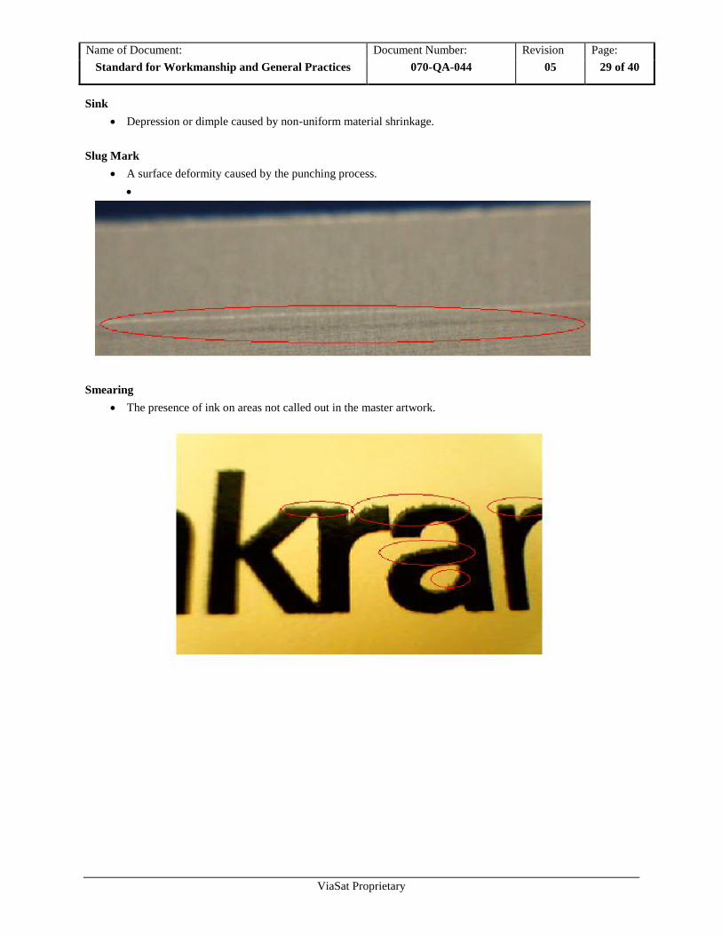
Smearing
The presence of ink on areas not called out in the master artwork.
Name of Document: Document Number: Revision Page:
Standard for Workmanship and General Practices 070-QA-044 05 30 of 40
ViaSat Proprietary
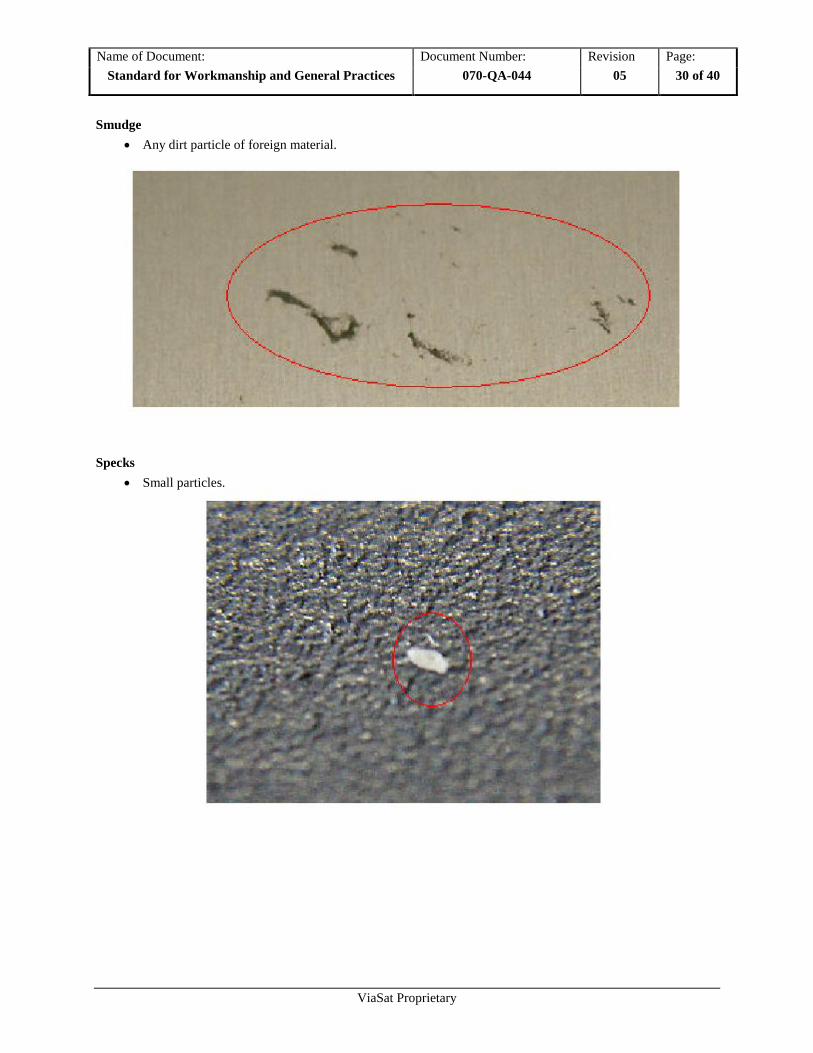
Smudge
Any dirt particle of foreign material.
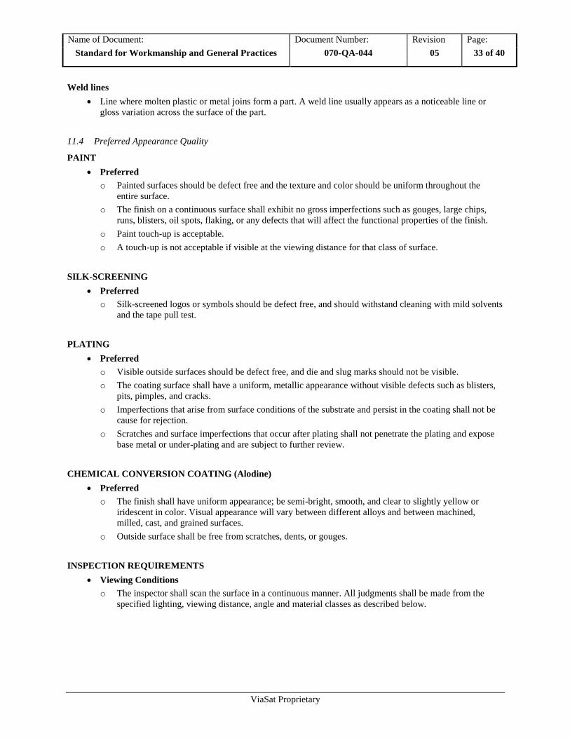
Specks
Small particles.

Name of Document: Document Number: Revision Page:
Standard for Workmanship and General Practices 070-QA-044 05 31 of 40
ViaSat Proprietary
Spot Weld Mark
Dish shaped surface caused by spot welding process.

Name of Document: Document Number: Revision Page:
Standard for Workmanship and General Practices 070-QA-044 05 32 of 40
ViaSat Proprietary
Tooling Marks
Very shallow lines which are parallel to bends in part.
Unwanted impact of a tool during punch process.
Caution: Some tooling marks are not avoidable in some process steps. E.g. punching, forming, and bending.
Texture
An area of rougher finish of plastic molded parts.
A rougher but uniform finish of painted parts.
Visible Surface
Surfaces those are visible when the enclosure or part is installed in a completed assembly.
Void
The failure of ink to define a graphic feature.
Warpage
Dimensional distortion in a part after molding, pressing or laminating. Twist or bows in the part.
Water Spots
Rough and not densely packed dull gray lines at plated material.
Name of Document: Document Number: Revision Page:
Standard for Workmanship and General Practices 070-QA-044 05 33 of 40
ViaSat Proprietary
Weld lines
Line where molten plastic or metal joins form a part. A weld line usually appears as a noticeable line or
gloss variation across the surface of the part.
11.4 Preferred Appearance Quality
PAINT
Preferred
o Painted surfaces should be defect free and the texture and color should be uniform throughout the
entire surface.
o The finish on a continuous surface shall exhibit no gross imperfections such as gouges, large chips,
runs, blisters, oil spots, flaking, or any defects that will affect the functional properties of the finish.
o Paint touch-up is acceptable.
o A touch-up is not acceptable if visible at the viewing distance for that class of surface.
SILK-SCREENING
Preferred
o Silk-screened logos or symbols should be defect free, and should withstand cleaning with mild solvents
and the tape pull test.
PLATING
Preferred
o Visible outside surfaces should be defect free, and die and slug marks should not be visible.
o The coating surface shall have a uniform, metallic appearance without visible defects such as blisters,
pits, pimples, and cracks.
o Imperfections that arise from surface conditions of the substrate and persist in the coating shall not be
cause for rejection.
o Scratches and surface imperfections that occur after plating shall not penetrate the plating and expose
base metal or under-plating and are subject to further review.
CHEMICAL CONVERSION COATING (Alodine)
Preferred
o The finish shall have uniform appearance; be semi-bright, smooth, and clear to slightly yellow or
iridescent in color. Visual appearance will vary between different alloys and between machined,
milled, cast, and grained surfaces.
o Outside surface shall be free from scratches, dents, or gouges.
INSPECTION REQUIREMENTS
Viewing Conditions
o The inspector shall scan the surface in a continuous manner. All judgments shall be made from the
specified lighting, viewing distance, angle and material classes as described below.

Name of Document: Document Number: Revision Page:
Standard for Workmanship and General Practices 070-QA-044 05 34 of 40
ViaSat Proprietary
11.5 Surface Categories
Class A
o Is a critical cosmetic surface usually front exterior surface which is most often closely viewed by the
user / customer.
o Panels
o Instrument cases
o Desktop cases
o Customer specified
Class B
o Is a semi-critical cosmetic surface usually exterior surface which is adjacent to Class A, not viewed as
often but easily seen.
Class C
o Is a non-critical cosmetic surface either exterior surface rarely viewed by the user / customer, such as
back surface; or an internal surface that is visible but not normally viewed by the user / customer.
11.6 Light Source
Light Specification
o White, cool artificial office lighting (e.g. fluorescent light)
o Do not use direct sunlight.
Light Intensity
o Uniform intensity between 70 and 120 foot-candles. (750 and 1250 Lux)
Caution: At levels of greater light intensity caution should be used to not over inspect the parts in
order of accentuate surface flaws.
Light position
o Reflection free, non-directional from the top.
Caution: No direct overhead light above inspection table.
11.7 Inspection Table Surface
The table surface should be made of a non-reflective dark color to avoid twilight conditions.
Preferred: Black rubber mat Acceptable: Dark blue or dark green rubber mat

Name of Document: Document Number: Revision Page:
Standard for Workmanship and General Practices 070-QA-044 05 35 of 40
ViaSat Proprietary
Unacceptable: Light color table surfaces e.g. white, gray, yellow, metallic etc.
Caution: Reflective light-colored surfaces eliminate or accentuate surface flaws.
11.8 Viewing Time
Class A
o Systems: Ten (10) seconds per 200 square inches per part
o Front Panels: Five (5) seconds per 50 square inches per part
Class B
o Seven (7) seconds per 200 square inches per part
Class C
o Five (5) seconds per 200 square inches per part
11.9 Viewing Orientation
During inspection, view objects in an orientation perpendicular to each surface. During assembly, view
objects in normal orientation of manufacturing process. In some cases inspection should be held prior to
assembly. Any visible surface flaw has to be verified against the acceptable defect matrix.
Caution: Parts shall not be manipulated to reflect a single light source in order to accentuate surface flaws.
11.10 Magnification Tools
Magnification tools may be used to find root causes for defects or to verify correctness of special areas.
Caution: Magnification is not to be used when inspecting for cosmetic defects.
11.11 Viewing Distance
Viewing Distances from the surface being inspected
Class A
o 24 Inch (610 mm)
Class B
o 30 Inch (760 mm)
Class C
o 36 Inch (760 mm)
Name of Document: Document Number: Revision Page:
Standard for Workmanship and General Practices 070-QA-044 05 36 of 40
ViaSat Proprietary
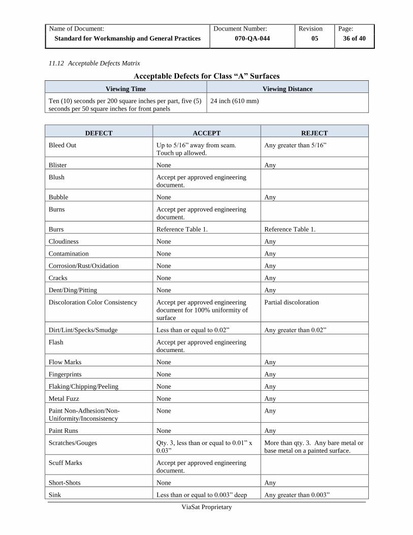
11.12 Acceptable Defects Matrix
Acceptable Defects for Class “A” Surfaces
Viewing Time Viewing Distance
Ten (10) seconds per 200 square inches per part, five (5)
seconds per 50 square inches for front panels
24 inch (610 mm)
DEFECT ACCEPT REJECT
Bleed Out Up to 5/16” away from seam.
Touch up allowed.
Any greater than 5/16”
Blister None Any
Blush Accept per approved engineering
document.
Bubble None Any
Burns Accept per approved engineering
document.
Burrs Reference Table 1. Reference Table 1.
Cloudiness None Any
Contamination None Any
Corrosion/Rust/Oxidation None Any
Cracks None Any
Dent/Ding/Pitting None Any
Discoloration Color Consistency Accept per approved engineering
document for 100% uniformity of
surface
Partial discoloration
Dirt/Lint/Specks/Smudge Less than or equal to 0.02” Any greater than 0.02”
Flash Accept per approved engineering
document.
Flow Marks None Any
Fingerprints None Any
Flaking/Chipping/Peeling None Any
Metal Fuzz None Any
Paint Non-Adhesion/Non-
Uniformity/Inconsistency
None Any
Paint Runs None Any
Scratches/Gouges Qty. 3, less than or equal to 0.01” x
0.03”
More than qty. 3. Any bare metal or
base metal on a painted surface.
Scuff Marks Accept per approved engineering
document.
Short-Shots None Any
Sink Less than or equal to 0.003” deep Any greater than 0.003”
Name of Document: Document Number: Revision Page:
Standard for Workmanship and General Practices 070-QA-044 05 37 of 40
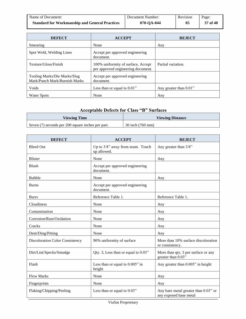
ViaSat Proprietary
DEFECT ACCEPT REJECT
Smearing None Any
Spot Weld, Welding Lines Accept per approved engineering
document.
Texture/Gloss/Finish 100% uniformity of surface, Accept
per approved engineering document.
Partial variation.
Tooling Marks/Die Marks/Slug
Mark/Punch Mark/Burnish Marks
Accept per approved engineering
document.
Voids Less than or equal to 0.01” Any greater than 0.01”
Water Spots None Any
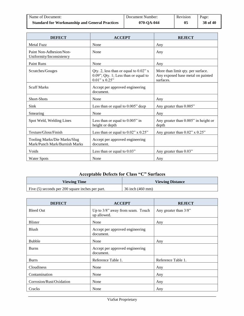
Acceptable Defects for Class “B” Surfaces
Viewing Time Viewing Distance
Seven (7) seconds per 200 square inches per part. 30 inch (760 mm)
DEFECT ACCEPT REJECT
Bleed Out Up to 3/8” away from seam. Touch
up allowed.
Any greater than 3/8”
Blister None Any
Blush Accept per approved engineering
document.
Bubble None Any
Burns Accept per approved engineering
document.
Burrs Reference Table 1. Reference Table 1.
Cloudiness None Any
Contamination None Any
Corrosion/Rust/Oxidation None Any
Cracks None Any
Dent/Ding/Pitting None Any
Discoloration Color Consistency 90% uniformity of surface More than 10% surface discoloration
or consistency.
Dirt/Lint/Specks/Smudge Qty. 3, Less than or equal to 0.03” More than qty. 3 per surface or any
greater than 0.03”
Flash Less than or equal to 0.005” in
height
Any greater than 0.005” in height
Flow Marks None Any
Fingerprints None Any
Flaking/Chipping/Peeling Less than or equal to 0.03” Any bare metal greater than 0.03” or
any exposed base metal
Name of Document: Document Number: Revision Page:
Standard for Workmanship and General Practices 070-QA-044 05 38 of 40
ViaSat Proprietary
DEFECT ACCEPT REJECT
Metal Fuzz None Any
Paint Non-Adhesion/Non-
Uniformity/Inconsistency
None Any
Paint Runs None Any
Scratches/Gouges Qty. 2, less than or equal to 0.02” x
0.09”; Qty. 1; Less than or equal to
0.01” x 0.25”
More than limit qty. per surface.
Any exposed base metal on painted
surfaces.
Scuff Marks Accept per approved engineering
document.
Short-Shots None Any
Sink Less than or equal to 0.005” deep Any greater than 0.005”
Smearing None Any
Spot Weld, Welding Lines Less than or equal to 0.005” in
height or depth
Any greater than 0.005” in height or
depth
Texture/Gloss/Finish Less than or equal to 0.02” x 0.25” Any greater than 0.02” x 0.25”
Tooling Marks/Die Marks/Slug
Mark/Punch Mark/Burnish Marks
Accept per approved engineering
document.
Voids Less than or equal to 0.03” Any greater than 0.03”
Water Spots None Any
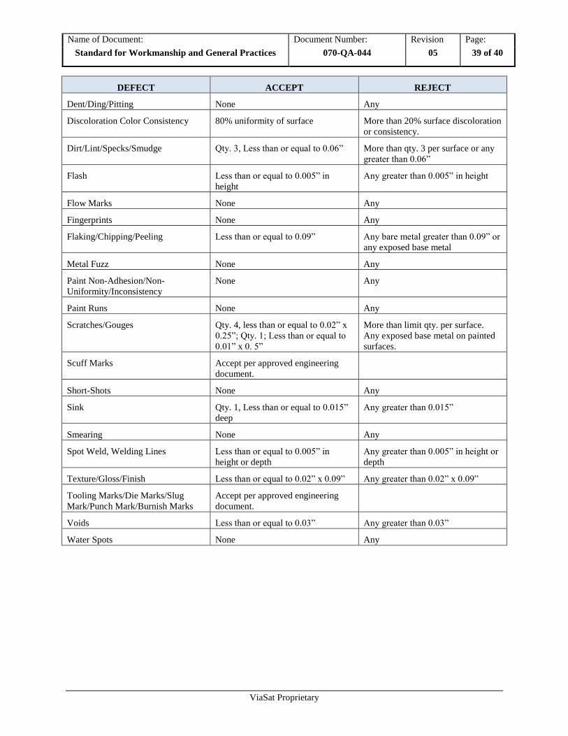
Acceptable Defects for Class “C” Surfaces
Viewing Time Viewing Distance
Five (5) seconds per 200 square inches per part. 36 inch (460 mm)
DEFECT ACCEPT REJECT
Bleed Out Up to 3/8” away from seam. Touch
up allowed.
Any greater than 3/8”
Blister None Any
Blush Accept per approved engineering
document.
Bubble None Any
Burns Accept per approved engineering
document.
Burrs Reference Table 1. Reference Table 1.
Cloudiness None Any
Contamination None Any
Corrosion/Rust/Oxidation None Any
Cracks None Any
Name of Document: Document Number: Revision Page:
Standard for Workmanship and General Practices 070-QA-044 05 39 of 40
ViaSat Proprietary
DEFECT ACCEPT REJECT
Dent/Ding/Pitting None Any
Discoloration Color Consistency 80% uniformity of surface More than 20% surface discoloration
or consistency.
Dirt/Lint/Specks/Smudge Qty. 3, Less than or equal to 0.06” More than qty. 3 per surface or any
greater than 0.06”
Flash Less than or equal to 0.005” in
height
Any greater than 0.005” in height
Flow Marks None Any
Fingerprints None Any
Flaking/Chipping/Peeling Less than or equal to 0.09” Any bare metal greater than 0.09” or
any exposed base metal
Metal Fuzz None Any
Paint Non-Adhesion/Non-
Uniformity/Inconsistency
None Any
Paint Runs None Any
Scratches/Gouges Qty. 4, less than or equal to 0.02” x
0.25”; Qty. 1; Less than or equal to
0.01” x 0. 5”
More than limit qty. per surface.
Any exposed base metal on painted
surfaces.
Scuff Marks Accept per approved engineering
document.
Short-Shots None Any
Sink Qty. 1, Less than or equal to 0.015”
deep
Any greater than 0.015”
Smearing None Any
Spot Weld, Welding Lines Less than or equal to 0.005” in
height or depth
Any greater than 0.005” in height or
depth
Texture/Gloss/Finish Less than or equal to 0.02” x 0.09” Any greater than 0.02” x 0.09”
Tooling Marks/Die Marks/Slug
Mark/Punch Mark/Burnish Marks
Accept per approved engineering
document.
Voids Less than or equal to 0.03” Any greater than 0.03”
Water Spots None Any
Name of Document: Document Number: Revision Page:
Standard for Workmanship and General Practices 070-QA-044 05 40 of 40
ViaSat Proprietary
12 References
Documents
IPC-A-600 – Workmanship Standards for printed circuit boards
IPC-A-610 – Workmanship Standards for electronic sub-assemblies
IPC/WHMA-A-620 – Requirements and Acceptance for Cable and Wire Harness Assemblies