1 Pipelining and Vector Processing Computer Organization Computer Architectures Lab PIPELINING AND...
37
1 Pipelining and Vector Processing Computer Organization Computer Architectures Lab PIPELINING AND VECTOR PROCESSING • Parallel Processing • Pipelining • Arithmetic Pipeline • Instruction Pipeline • RISC Pipeline • Vector Processing • Array Processors
-
Upload
alyson-shields -
Category
Documents
-
view
299 -
download
3
Transcript of 1 Pipelining and Vector Processing Computer Organization Computer Architectures Lab PIPELINING AND...
1Pipelining and Vector Processing
Computer Organization Computer Architectures Lab
PIPELINING AND VECTOR PROCESSING
• Parallel Processing
• Pipelining
• Arithmetic Pipeline
• Instruction Pipeline
• RISC Pipeline
• Vector Processing
• Array Processors
2Pipelining and Vector Processing
Computer Organization Computer Architectures Lab
PARALLEL PROCESSING
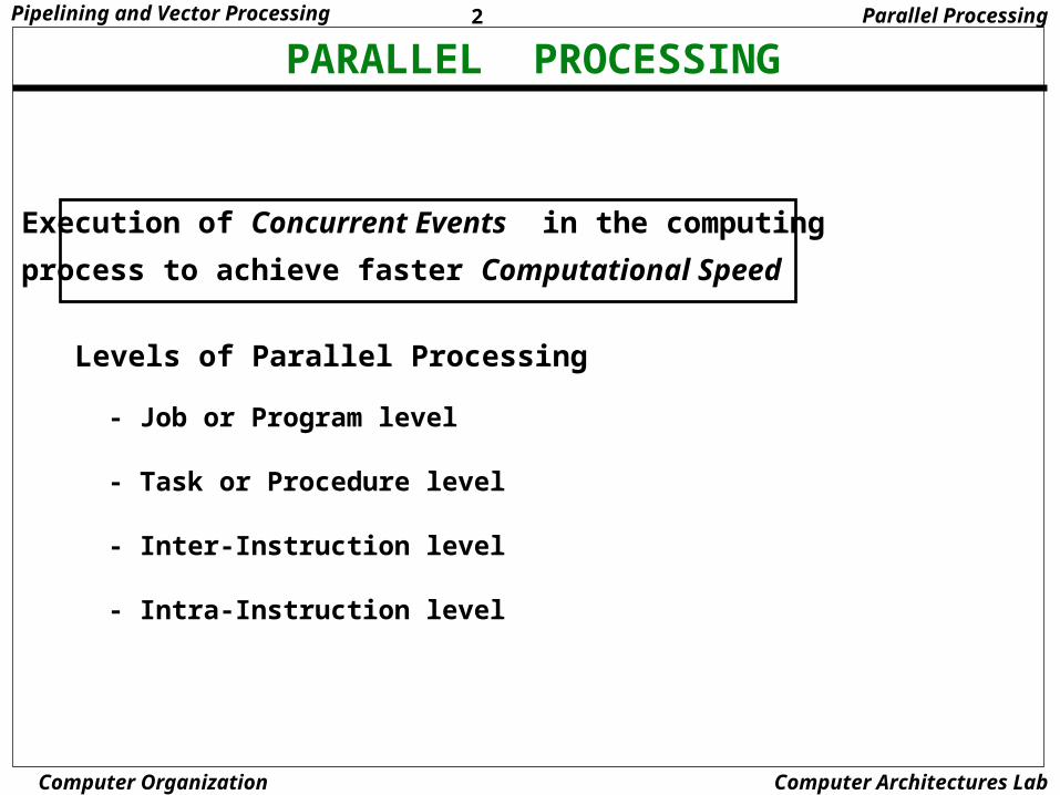
Levels of Parallel Processing
- Job or Program level
- Task or Procedure level
- Inter-Instruction level
- Intra-Instruction level
Execution of Concurrent Events in the computing
process to achieve faster Computational Speed
Parallel Processing
3Pipelining and Vector Processing
Computer Organization Computer Architectures Lab
PARALLEL COMPUTERS
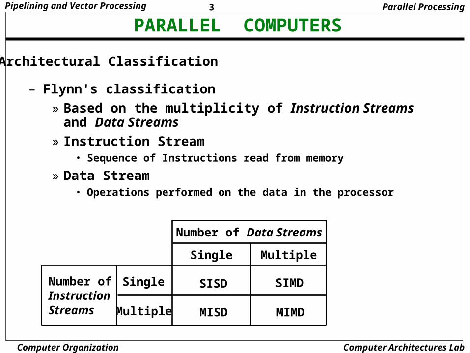
Architectural Classification
Number of Data Streams
Number ofInstructionStreams
Single
Multiple
Single Multiple
SISD SIMD
MISD MIMD
Parallel Processing
– Flynn's classification
» Based on the multiplicity of Instruction Streams and Data Streams
» Instruction Stream• Sequence of Instructions read from memory
» Data Stream• Operations performed on the data in the processor
4Pipelining and Vector Processing
Computer Organization Computer Architectures Lab
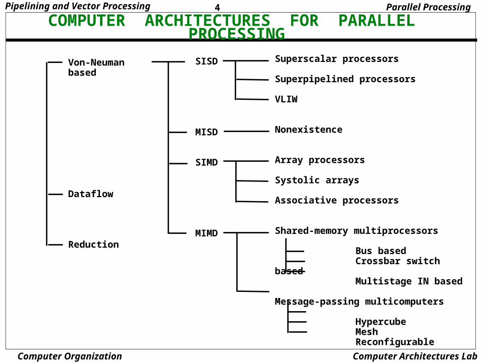
COMPUTER ARCHITECTURES FOR PARALLEL PROCESSING
Von-Neuman based
Dataflow
Reduction
SISD
MISD
SIMD
MIMD
Superscalar processors
Superpipelined processors
VLIW
Nonexistence
Array processors
Systolic arrays
Associative processors
Shared-memory multiprocessors
Bus based Crossbar switch based Multistage IN based
Message-passing multicomputers
Hypercube Mesh Reconfigurable
Parallel Processing
5Pipelining and Vector Processing
Computer Organization Computer Architectures Lab
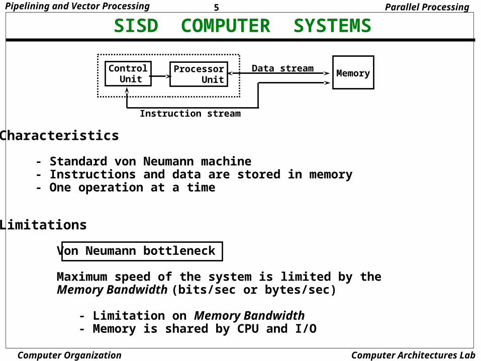
SISD COMPUTER SYSTEMS
Control Unit
Processor Unit
Memory
Instruction stream
Data stream
Characteristics
- Standard von Neumann machine - Instructions and data are stored in memory - One operation at a time
Limitations
Von Neumann bottleneck
Maximum speed of the system is limited by the Memory Bandwidth (bits/sec or bytes/sec)
- Limitation on Memory Bandwidth - Memory is shared by CPU and I/O
Parallel Processing
6Pipelining and Vector Processing
Computer Organization Computer Architectures Lab
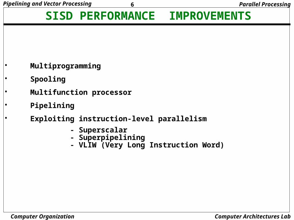
SISD PERFORMANCE IMPROVEMENTS
• Multiprogramming
• Spooling
• Multifunction processor
• Pipelining
• Exploiting instruction-level parallelism
- Superscalar - Superpipelining - VLIW (Very Long Instruction Word)
Parallel Processing
7Pipelining and Vector Processing
Computer Organization Computer Architectures Lab
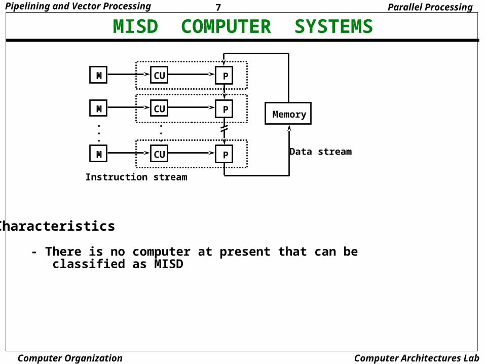
MISD COMPUTER SYSTEMS
M CU P
M CU P
M CU P
•••
•••
Memory
Instruction stream
Data stream
Characteristics
- There is no computer at present that can be classified as MISD
Parallel Processing
8Pipelining and Vector Processing
Computer Organization Computer Architectures Lab
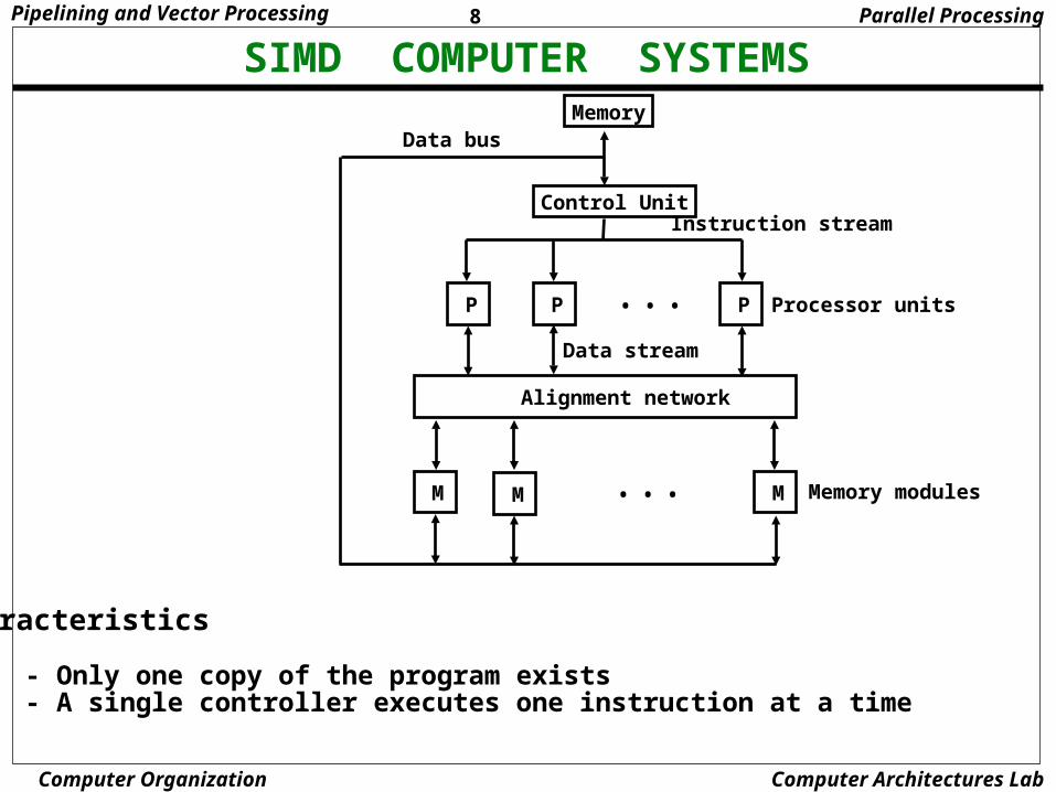
SIMD COMPUTER SYSTEMS
Control Unit
Memory
Alignment network
P P P• • •
M MM • • •
Data bus
Instruction stream
Data stream
Processor units
Memory modules
Characteristics
- Only one copy of the program exists - A single controller executes one instruction at a time
Parallel Processing
9Pipelining and Vector Processing
Computer Organization Computer Architectures Lab
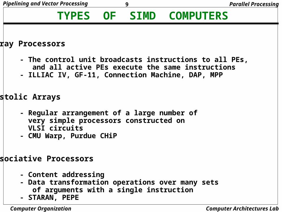
TYPES OF SIMD COMPUTERS
Array Processors
- The control unit broadcasts instructions to all PEs, and all active PEs execute the same instructions - ILLIAC IV, GF-11, Connection Machine, DAP, MPP
Systolic Arrays
- Regular arrangement of a large number of very simple processors constructed on VLSI circuits - CMU Warp, Purdue CHiP
Associative Processors
- Content addressing - Data transformation operations over many sets of arguments with a single instruction - STARAN, PEPE
Parallel Processing
10Pipelining and Vector Processing
Computer Organization Computer Architectures Lab
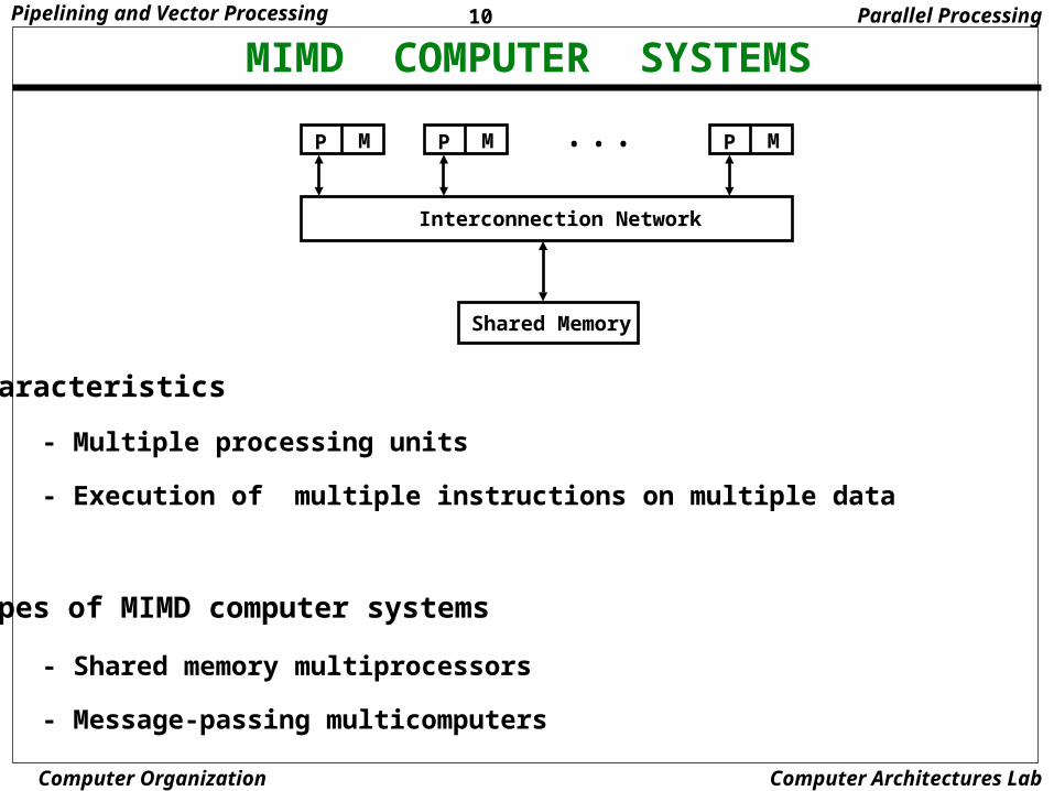
MIMD COMPUTER SYSTEMS
Interconnection Network
P M P MP M • • •
Shared Memory
Characteristics
- Multiple processing units
- Execution of multiple instructions on multiple data
Types of MIMD computer systems
- Shared memory multiprocessors
- Message-passing multicomputers
Parallel Processing

11Pipelining and Vector Processing
Computer Organization Computer Architectures Lab
SHARED MEMORY MULTIPROCESSORS
Characteristics All processors have equally direct access to
one large memory address space
Example systems Bus and cache-based systems - Sequent Balance, Encore Multimax Multistage IN-based systems - Ultracomputer, Butterfly, RP3, HEP Crossbar switch-based systems - C.mmp, Alliant FX/8
Limitations Memory access latency Hot spot problem
Interconnection Network(IN)
• • •
• • •P PP
M MM
Buses,Multistage IN,Crossbar Switch
Parallel Processing
12Pipelining and Vector Processing
Computer Organization Computer Architectures Lab
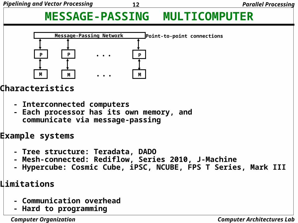
MESSAGE-PASSING MULTICOMPUTER
Characteristics
- Interconnected computers - Each processor has its own memory, and communicate via message-passing
Example systems
- Tree structure: Teradata, DADO - Mesh-connected: Rediflow, Series 2010, J-Machine - Hypercube: Cosmic Cube, iPSC, NCUBE, FPS T Series, Mark III
Limitations
- Communication overhead - Hard to programming
Message-Passing Network
• • •P PP
M M M• • •
Point-to-point connections
Parallel Processing
13Pipelining and Vector Processing
Computer Organization Computer Architectures Lab
PIPELINING
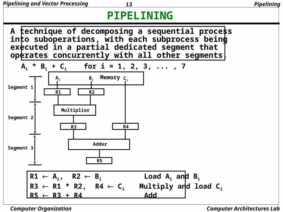
R1 Ai, R2 Bi Load Ai and Bi
R3 R1 * R2, R4 Ci Multiply and load Ci
R5 R3 + R4 Add
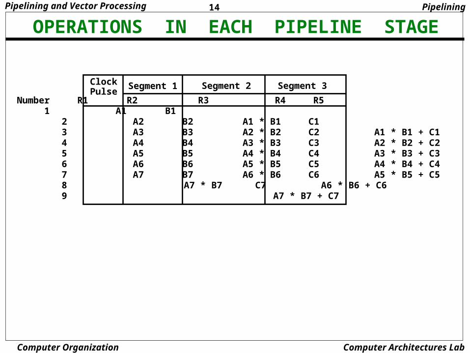
A technique of decomposing a sequential process into suboperations, with each subprocess being executed in a partial dedicated segment that operates concurrently with all other segments.
Ai * Bi + Ci for i = 1, 2, 3, ... , 7
Ai
R1 R2
Multiplier
R3 R4
Adder
R5
Memory
Pipelining
Bi Ci
Segment 1
Segment 2
Segment 3
14Pipelining and Vector Processing
Computer Organization Computer Architectures Lab
OPERATIONS IN EACH PIPELINE STAGE
ClockPulse
Segment 1 Segment 2 Segment 3
Number R1 R2 R3 R4 R5 1 A1 B1
2 A2 B2 A1 * B1 C1 3 A3 B3 A2 * B2 C2 A1 * B1 + C1 4 A4 B4 A3 * B3 C3 A2 * B2 + C2 5 A5 B5 A4 * B4 C4 A3 * B3 + C3 6 A6 B6 A5 * B5 C5 A4 * B4 + C4 7 A7 B7 A6 * B6 C6 A5 * B5 + C5 8 A7 * B7 C7 A6 * B6 + C6 9 A7 * B7 + C7
Pipelining
15Pipelining and Vector Processing
Computer Organization Computer Architectures Lab
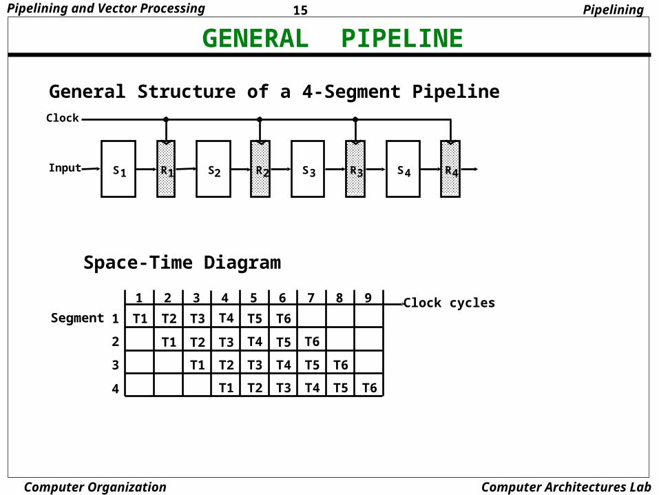
GENERAL PIPELINE
General Structure of a 4-Segment Pipeline
S R1 1 S R2 2 S R3 3 S R4 4Input
Clock
Space-Time Diagram
1 2 3 4 5 6 7 8 9
T1
T1
T1
T1
T2
T2
T2
T2
T3
T3
T3
T3 T4
T4
T4
T4 T5
T5
T5
T5 T6
T6
T6
T6Clock cycles
Segment 1
2
3
4
Pipelining
16Pipelining and Vector Processing
Computer Organization Computer Architectures Lab
PIPELINE SPEEDUP
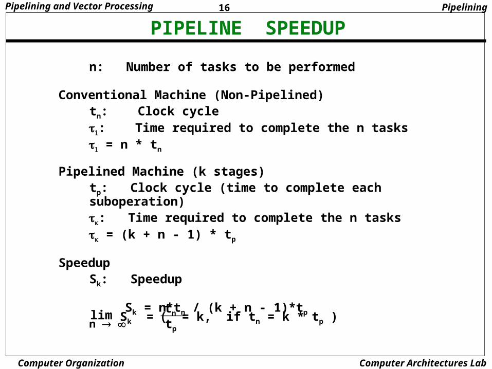
n: Number of tasks to be performed
Conventional Machine (Non-Pipelined)tn: Clock cycle : Time required to complete the n tasks = n * tn
Pipelined Machine (k stages)tp: Clock cycle (time to complete each suboperation): Time required to complete the n tasks = (k + n - 1) * tp
SpeedupSk: Speedup
Sk = n*tn / (k + n - 1)*tp
n Sk =
tn
tp
( = k, if tn = k * tp )lim
Pipelining
17Pipelining and Vector Processing
Computer Organization Computer Architectures Lab
PIPELINE AND MULTIPLE FUNCTION UNITS
P1
I i
P2
I i+1
P3
I i+2
P4
I i+3
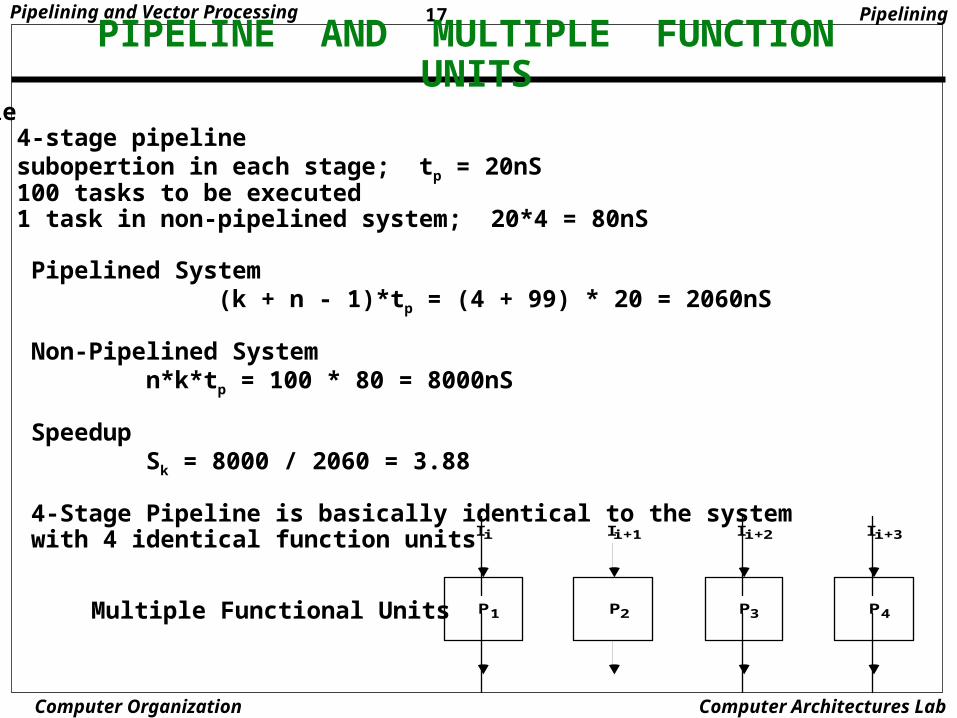
Multiple Functional Units
Example - 4-stage pipeline - subopertion in each stage; tp = 20nS - 100 tasks to be executed - 1 task in non-pipelined system; 20*4 = 80nS Pipelined System (k + n - 1)*tp = (4 + 99) * 20 = 2060nS
Non-Pipelined System n*k*tp = 100 * 80 = 8000nS
Speedup Sk = 8000 / 2060 = 3.88
4-Stage Pipeline is basically identical to the system with 4 identical function units
Pipelining
18Pipelining and Vector Processing
Computer Organization Computer Architectures Lab
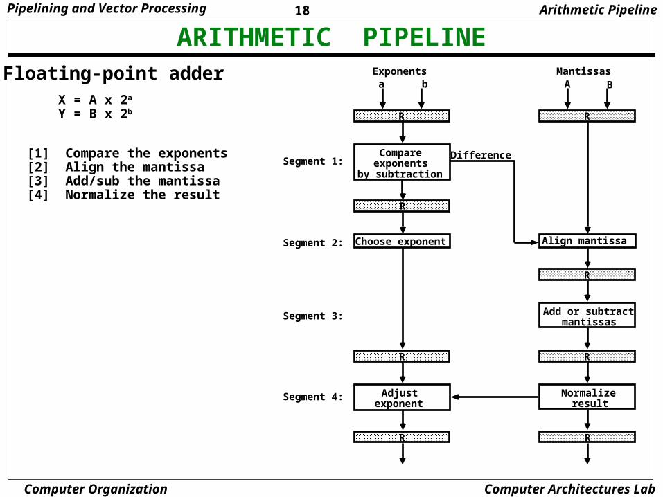
ARITHMETIC PIPELINEFloating-point adder
[1] Compare the exponents[2] Align the mantissa[3] Add/sub the mantissa[4] Normalize the result
X = A x 2a
Y = B x 2b R
Compareexponents
by subtraction
a b
R
Choose exponent
Exponents
R
A B
Align mantissa
Mantissas
Difference
R
Add or subtractmantissas
R
Normalizeresult
R
R
Adjustexponent
R
Segment 1:
Segment 2:
Segment 3:
Segment 4:
Arithmetic Pipeline
19Pipelining and Vector Processing
Computer Organization Computer Architectures Lab
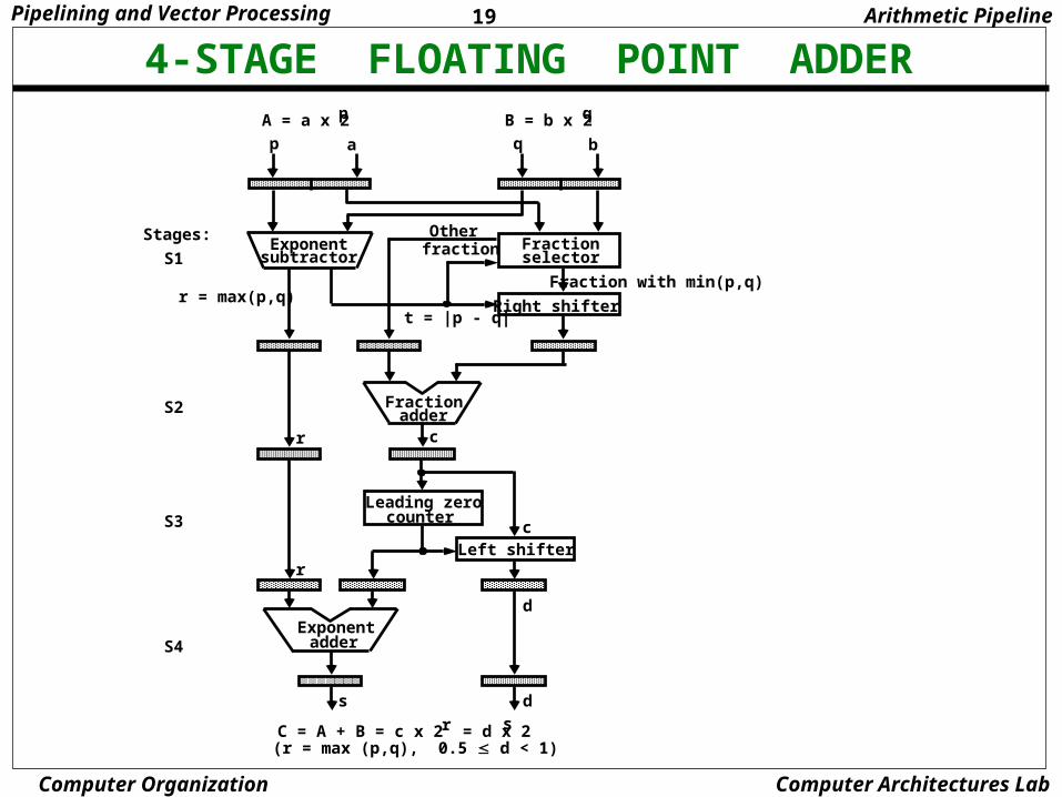
4-STAGE FLOATING POINT ADDERA = a x 2p B = b x 2q
p a q b
Exponentsubtractor
Fractionselector
Fraction with min(p,q)
Right shifter
Otherfraction
t = |p - q|r = max(p,q)
Fractionadder
Leading zerocounter
r c
Left shifterc
Exponentadder
r
s d
d
Stages:
S1
S2
S3
S4
C = A + B = c x 2 = d x 2 r s
(r = max (p,q), 0.5 d < 1)
Arithmetic Pipeline
20Pipelining and Vector Processing
Computer Organization Computer Architectures Lab
INSTRUCTION CYCLE
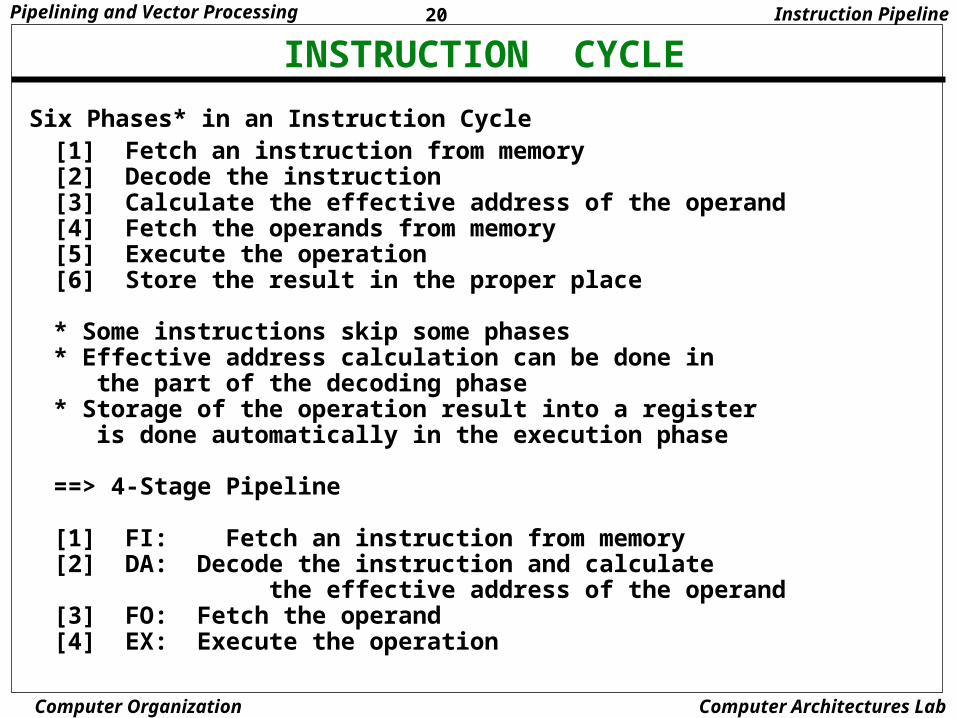
Six Phases* in an Instruction Cycle[1] Fetch an instruction from memory[2] Decode the instruction[3] Calculate the effective address of the operand[4] Fetch the operands from memory[5] Execute the operation[6] Store the result in the proper place
* Some instructions skip some phases* Effective address calculation can be done in the part of the decoding phase* Storage of the operation result into a register is done automatically in the execution phase
==> 4-Stage Pipeline
[1] FI: Fetch an instruction from memory[2] DA: Decode the instruction and calculate the effective address of the operand[3] FO: Fetch the operand[4] EX: Execute the operation
Instruction Pipeline
21Pipelining and Vector Processing
Computer Organization Computer Architectures Lab
INSTRUCTION PIPELINE
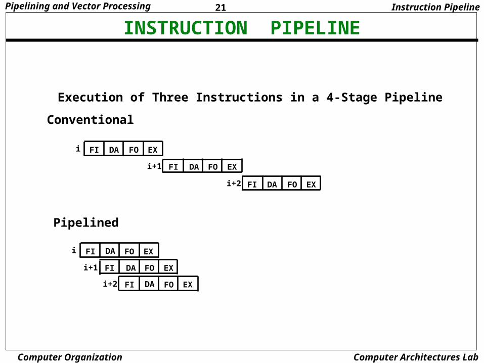
Execution of Three Instructions in a 4-Stage Pipeline
Instruction Pipeline
FI DA FO EX
FI DA FO EX
FI DA FO EX
i
i+1
i+2
Conventional
Pipelined
FI DA FO EX
FI DA FO EX
FI DA FO EX
i
i+1
i+2
22Pipelining and Vector Processing
Computer Organization Computer Architectures Lab
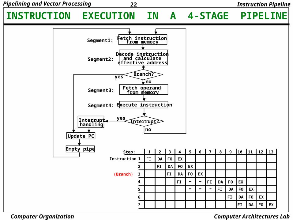
INSTRUCTION EXECUTION IN A 4-STAGE PIPELINE
1 2 3 4 5 6 7 8 9 10 12 1311
FI DA FO EX1
FI DA FO EX
FI DA FO EX
FI DA FO EX
FI DA FO EX
FI DA FO EX
FI DA FO EX
2
3
4
5
6
7
FI
Step:
Instruction
(Branch)
Instruction Pipeline
Fetch instructionfrom memory
Decode instructionand calculate
effective address
Branch?
Fetch operandfrom memory
Execute instruction
Interrupt?Interrupthandling
Update PC
Empty pipe
no
yes
yesno
Segment1:
Segment2:
Segment3:
Segment4:
23Pipelining and Vector Processing
Computer Organization Computer Architectures Lab
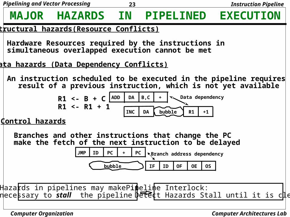
MAJOR HAZARDS IN PIPELINED EXECUTIONStructural hazards(Resource Conflicts) Hardware Resources required by the instructions in simultaneous overlapped execution cannot be met
Data hazards (Data Dependency Conflicts)
An instruction scheduled to be executed in the pipeline requires the result of a previous instruction, which is not yet available
JMP ID PC + PC
bubble IF ID OF OE OS
Branch address dependency
Hazards in pipelines may make it necessary to stall the pipeline
Pipeline Interlock: Detect Hazards Stall until it is cleared
Instruction Pipeline
ADD DA B,C +
INC DA +1R1bubble
Data dependencyR1 <- B + CR1 <- R1 + 1
Control hazards
Branches and other instructions that change the PC make the fetch of the next instruction to be delayed
24Pipelining and Vector Processing
Computer Organization Computer Architectures Lab
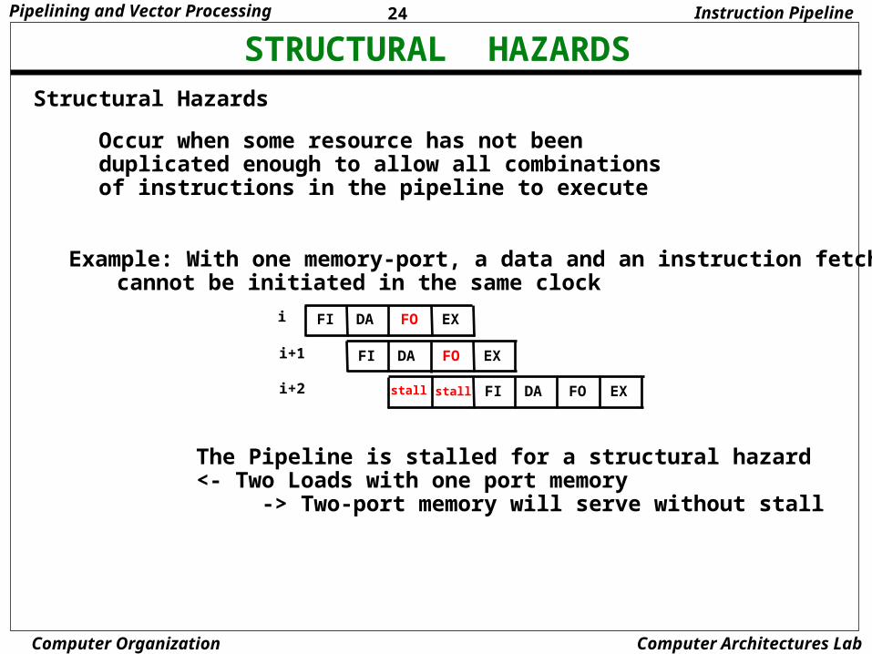
STRUCTURAL HAZARDSStructural Hazards
Occur when some resource has not been duplicated enough to allow all combinations of instructions in the pipeline to execute
Example: With one memory-port, a data and an instruction fetch cannot be initiated in the same clock
The Pipeline is stalled for a structural hazard<- Two Loads with one port memory -> Two-port memory will serve without stall
Instruction Pipeline
FI DA FO EXi
i+1
i+2
FI DA FO EX
FI DA FO EXstallstall
25Pipelining and Vector Processing
Computer Organization Computer Architectures Lab
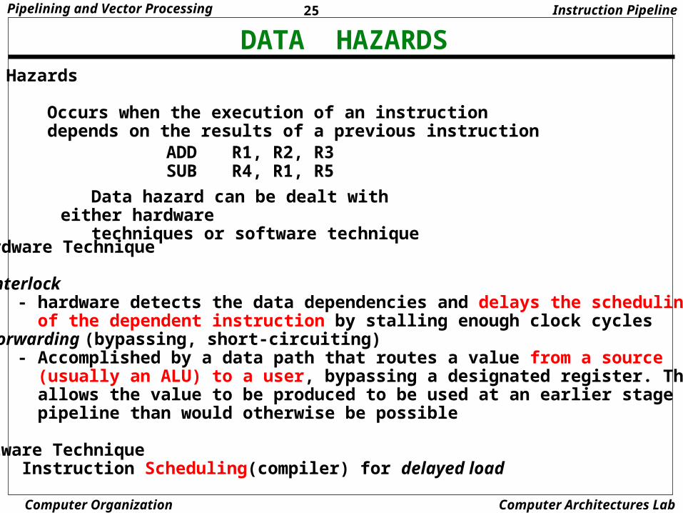
DATA HAZARDSData Hazards
Occurs when the execution of an instruction depends on the results of a previous instruction
ADD R1, R2, R3SUB R4, R1, R5
Hardware Technique
Interlock - hardware detects the data dependencies and delays the scheduling of the dependent instruction by stalling enough clock cycles
Forwarding (bypassing, short-circuiting)- Accomplished by a data path that routes a value from a source (usually an ALU) to a user, bypassing a designated register. This allows the value to be produced to be used at an earlier stage in the pipeline than would otherwise be possible
Software Technique Instruction Scheduling(compiler) for delayed load
Data hazard can be dealt with either hardware techniques or software technique
Instruction Pipeline
26Pipelining and Vector Processing
Computer Organization Computer Architectures Lab
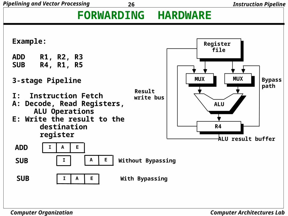
FORWARDING HARDWARE
Register file
Result write bus
Bypass path
ALU result buffer
MUX
ALU
R4
MUX
Instruction Pipeline
Example:
ADD R1, R2, R3SUB R4, R1, R5
3-stage Pipeline
I: Instruction FetchA: Decode, Read Registers, ALU OperationsE: Write the result to the
destination register
I A EADD
SUB I A E Without Bypassing
I A ESUB With Bypassing
27Pipelining and Vector Processing
Computer Organization Computer Architectures Lab
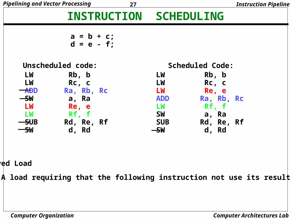
INSTRUCTION SCHEDULING
a = b + c;d = e - f;
Unscheduled code:
Delayed Load
A load requiring that the following instruction not use its result
Scheduled Code:LW Rb, bLW Rc, cLW Re, eADD Ra, Rb, RcLW Rf, fSW a, RaSUB Rd, Re, RfSW d, Rd
LW Rb, bLW Rc, cADD Ra, Rb, RcSW a, RaLW Re, eLW Rf, fSUB Rd, Re, RfSW d, Rd
Instruction Pipeline
28Pipelining and Vector Processing
Computer Organization Computer Architectures Lab
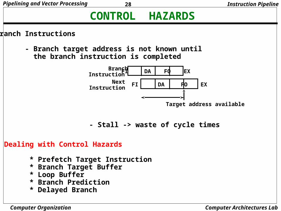
CONTROL HAZARDS
Branch Instructions
- Branch target address is not known until the branch instruction is completed
- Stall -> waste of cycle times
FI DA FO EX
FI DA FO EX
BranchInstruction
NextInstruction
Target address available
Dealing with Control Hazards
* Prefetch Target Instruction * Branch Target Buffer * Loop Buffer * Branch Prediction * Delayed Branch
Instruction Pipeline
29Pipelining and Vector Processing
Computer Organization Computer Architectures Lab
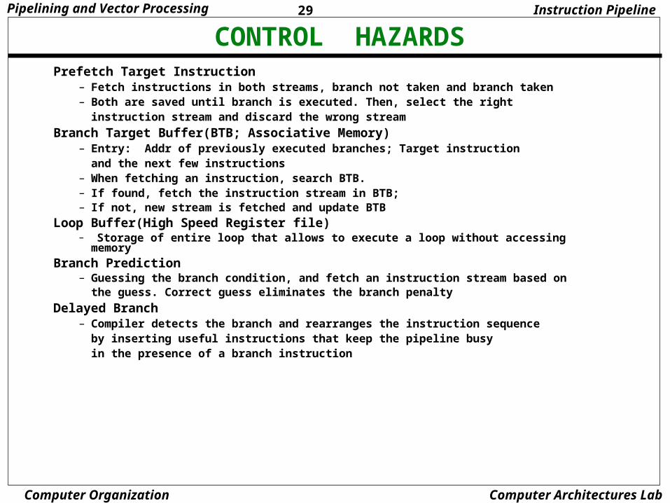
CONTROL HAZARDSInstruction Pipeline
Prefetch Target Instruction– Fetch instructions in both streams, branch not taken and branch taken– Both are saved until branch is executed. Then, select the right
instruction stream and discard the wrong stream
Branch Target Buffer(BTB; Associative Memory)– Entry: Addr of previously executed branches; Target instruction
and the next few instructions– When fetching an instruction, search BTB.– If found, fetch the instruction stream in BTB; – If not, new stream is fetched and update BTB
Loop Buffer(High Speed Register file)– Storage of entire loop that allows to execute a loop without accessing memory
Branch Prediction– Guessing the branch condition, and fetch an instruction stream based on
the guess. Correct guess eliminates the branch penalty
Delayed Branch– Compiler detects the branch and rearranges the instruction sequence
by inserting useful instructions that keep the pipeline busy in the presence of a branch instruction
30Pipelining and Vector Processing
Computer Organization Computer Architectures Lab
RISC PIPELINE
Instruction Cycles of Three-Stage Instruction Pipeline
RISC Pipeline
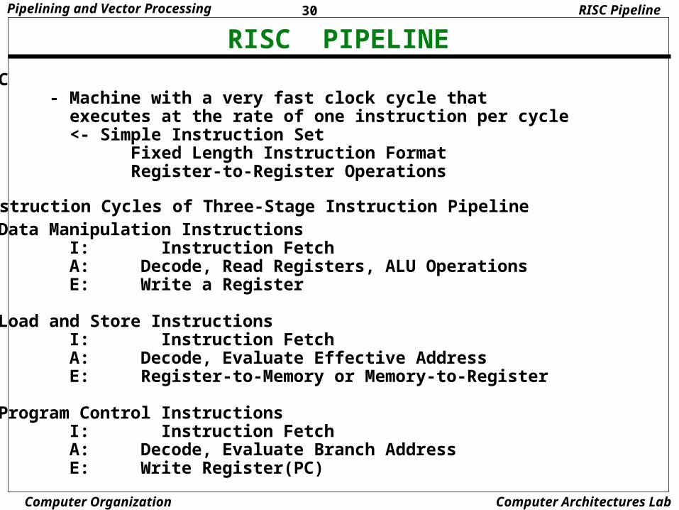
RISC - Machine with a very fast clock cycle that executes at the rate of one instruction per cycle <- Simple Instruction Set Fixed Length Instruction Format Register-to-Register Operations
Data Manipulation Instructions I: Instruction Fetch A: Decode, Read Registers, ALU Operations E: Write a Register
Load and Store Instructions I: Instruction Fetch A: Decode, Evaluate Effective Address E: Register-to-Memory or Memory-to-Register Program Control Instructions I: Instruction Fetch A: Decode, Evaluate Branch Address E: Write Register(PC)

31Pipelining and Vector Processing
Computer Organization Computer Architectures Lab
DELAYED LOAD
Three-segment pipeline timing
Pipeline timing with data conflict
clock cycle 1 2 3 4 5 6 Load R1 I A E Load R2 I A E Add R1+R2 I A E Store R3 I A E
Pipeline timing with delayed load
clock cycle 1 2 3 4 5 6 7 Load R1 I A E Load R2 I A E NOP I A E Add R1+R2 I A E Store R3 I A E
LOAD: R1 M[address 1] LOAD: R2 M[address 2] ADD: R3 R1 + R2 STORE: M[address 3] R3
RISC Pipeline
The data dependency is takencare by the compiler rather than the hardware
32Pipelining and Vector Processing
Computer Organization Computer Architectures Lab
DELAYED BRANCH
1I
3 4 652Clock cycles:
1. Load A
2. Increment
4. Subtract
5. Branch to X
7
3. Add
8
6. NOP
E
I A E
I A E
I A E
I A E
I A E
9 10
7. NOP
8. Instr. in X
I A E
I A E
1
I
3 4 652Clock cycles:
1. Load A
2. Increment
4. Add
5. Subtract
7
3. Branch to X
8
6. Instr. in X
E
I A E
I A E
I A E
I A E
I A E
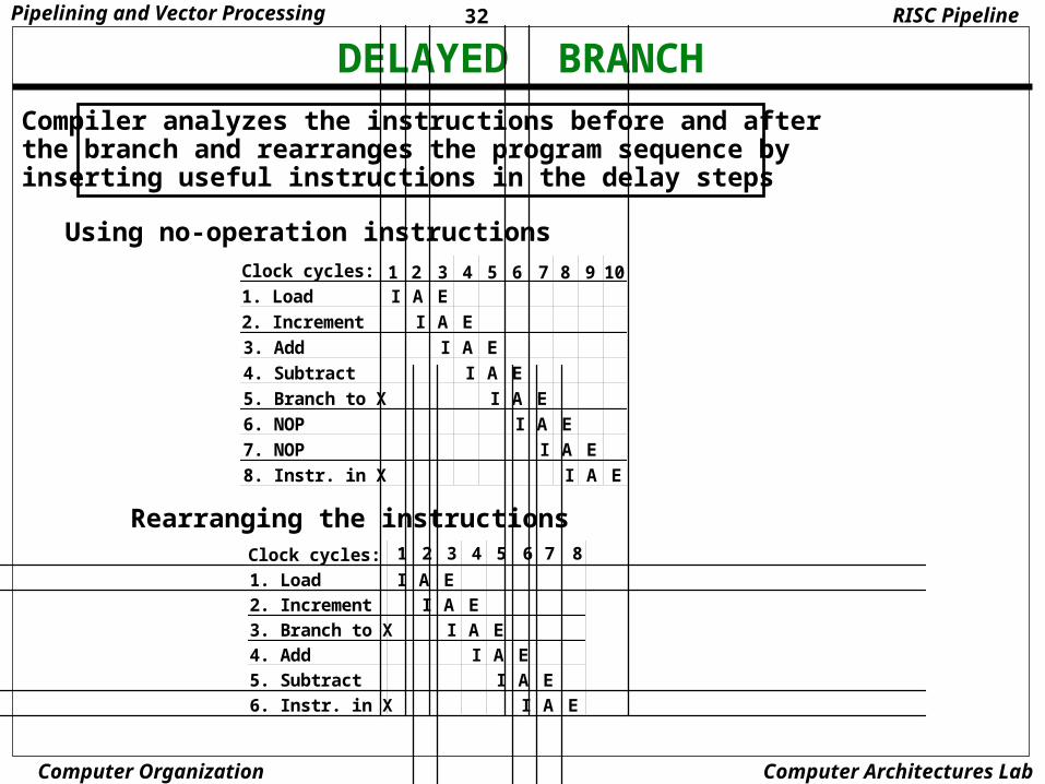
Compiler analyzes the instructions before and after the branch and rearranges the program sequence by inserting useful instructions in the delay steps
Using no-operation instructions
Rearranging the instructions
RISC Pipeline
33Pipelining and Vector Processing
Computer Organization Computer Architectures Lab
VECTOR PROCESSINGVector Processing
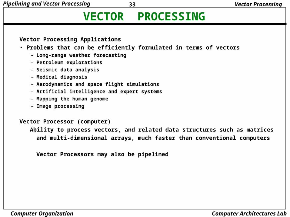
Vector Processing Applications
• Problems that can be efficiently formulated in terms of vectors– Long-range weather forecasting
– Petroleum explorations
– Seismic data analysis
– Medical diagnosis
– Aerodynamics and space flight simulations
– Artificial intelligence and expert systems
– Mapping the human genome
– Image processing
Vector Processor (computer)
Ability to process vectors, and related data structures such as matrices
and multi-dimensional arrays, much faster than conventional computers
Vector Processors may also be pipelined

34Pipelining and Vector Processing
Computer Organization Computer Architectures Lab
VECTOR PROGRAMMING
DO 20 I = 1, 10020 C(I) = B(I) + A(I)
Conventional computer
Initialize I = 020 Read A(I) Read B(I) Store C(I) = A(I) + B(I) Increment I = i + 1 If I 100 goto 20
Vector computer
C(1:100) = A(1:100) + B(1:100)
Vector Processing

35Pipelining and Vector Processing
Computer Organization Computer Architectures Lab
VECTOR INSTRUCTIONS
f1: V Vf2: V Sf3: V x V Vf4: V x S V
V: Vector operandS: Scalar operand
Type Mnemonic Description (I = 1, ..., n)
Vector Processing
f1 VSQR Vector square root B(I) SQR(A(I))
VSIN Vector sine B(I) sin(A(I))
VCOM Vector complement A(I) A(I)
f2 VSUM Vector summation S A(I)
VMAX Vector maximum S max{A(I)}
f3 VADD Vector add C(I) A(I) + B(I)
VMPY Vector multiply C(I) A(I) * B(I)
VAND Vector AND C(I) A(I) . B(I)
VLAR Vector larger C(I) max(A(I),B(I))
VTGE Vector test > C(I) 0 if A(I) < B(I)
C(I) 1 if A(I) > B(I)
f4 SADD Vector-scalar add B(I) S + A(I)
SDIV Vector-scalar divide B(I) A(I) / S
36Pipelining and Vector Processing
Computer Organization Computer Architectures Lab
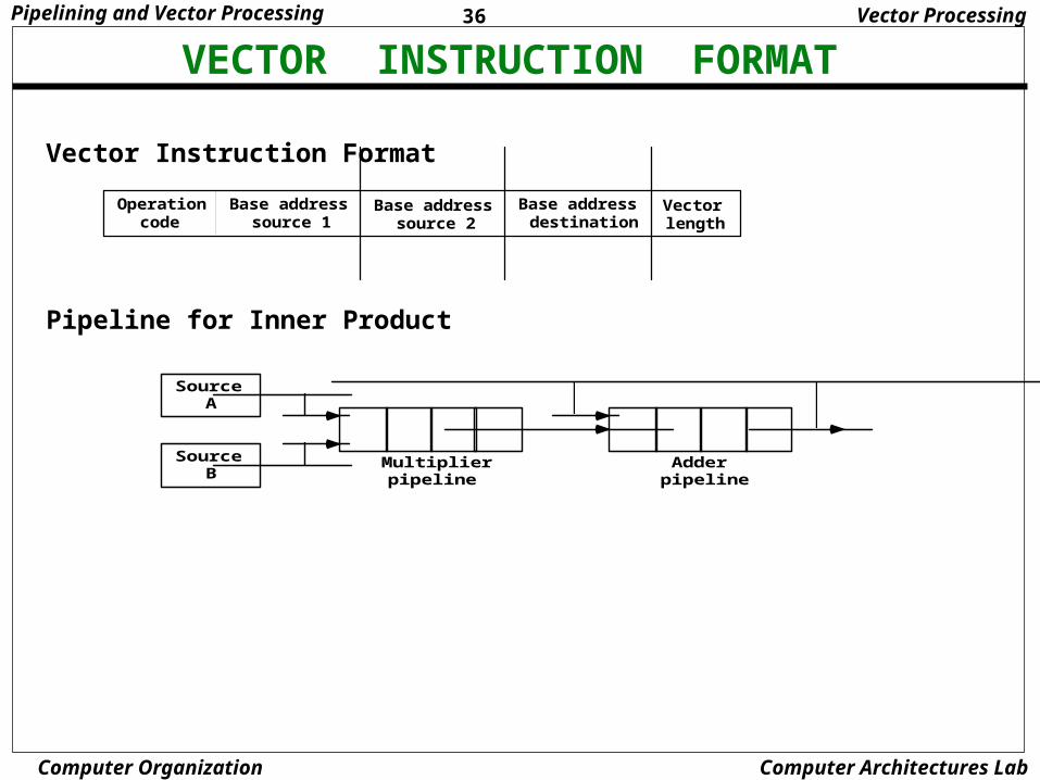
VECTOR INSTRUCTION FORMAT
Operation code
Base address source 1
Base address source 2
Base address destination
Vector length
Vector Processing
Vector Instruction Format
Source A
Source B
Multiplier pipeline
Adder pipeline
Pipeline for Inner Product
37Pipelining and Vector Processing
Computer Organization Computer Architectures Lab
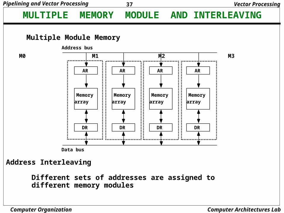
MULTIPLE MEMORY MODULE AND INTERLEAVINGVector Processing
Multiple Module Memory
Address Interleaving Different sets of addresses are assigned to different memory modules
AR
Memory
array
DR
AR
Memory
array
DR
AR
Memory
array
DR
AR
Memory
array
DR
Address bus
Data bus
M0 M1 M2 M3


![Pipelining & Parallel Processing - ics.kaist.ac.krics.kaist.ac.kr/ee878_2018f/[EE878]3 Pipelining and Parallel Processing.pdf · Pipelining processing By using pipelining latches](https://static.fdocuments.net/doc/165x107/5d40e26d88c99391748d47fb/pipelining-parallel-processing-icskaistackricskaistackree8782018fee8783.jpg)