
1 Operating Systems Part VI: Mass- Storage Structure.
25
1 Operating Systems Part VI: Mass- Storage Structure
-
Upload
ira-mcdonald -
Category
Documents
-
view
215 -
download
2
Transcript of 1 Operating Systems Part VI: Mass- Storage Structure.

1
Operating Systems
Part VI: Mass-Storage Structure
2
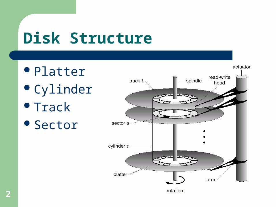
Disk Structure
PlatterCylinderTrackSector

3
Data Transfer
Seek time: time to get to the track/cylinder containing the sector
Rotational latency: time to get to the desired sector
Disk bandwidth: number of bytes transferred per unit time (a.k.a. transfer rate)

4
Disk Scheduling
FCFS (First Come First Served)– Simplest to implement– Intrinsically fair– Does not provide the fastest service– Example
98,183,37,122,14,124,65,67Assume start at cylinder 53

5
Disk Scheduling
FCFS (First Come First Served)

6
Disk Scheduling
SSTF (Shortest Seek Time First)– Selects the request with the minimum seek
time from the current head position– Essentially a form of SJF– May cause starvation– Not optimal, but substantial improvement over
FCFS

7
Disk Scheduling
SSTF (Shortest Seek Time First)

8
Disk Scheduling
SCAN Scheduling– Sometimes called the elevator algorithm– Starts at one end of disk and moves toward
other end, servicing requests as it reaches each cylinder, until it gets to other end
– Head continuously scans back and forth– Disadvantage: When head reverses direction,
what happens to density of request in vicinity?

9
Disk Scheduling
SCAN Scheduling

10
Disk Scheduling
C-SCAN Scheduling– Variation of SCAN but returns to beginning of
disk without servicing requests on return trip– Treats cylinder as circular list that wraps
around from final cylinder to the first one

11
Disk Scheduling
C-SCAN Scheduling
12
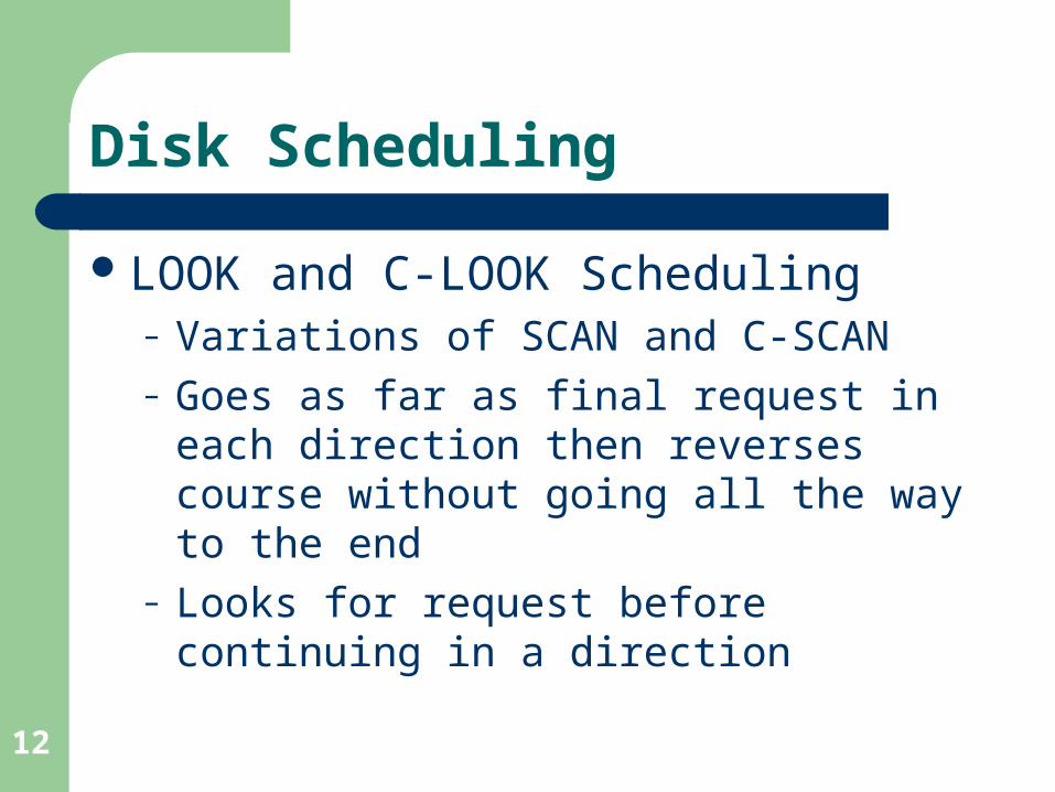
Disk Scheduling
LOOK and C-LOOK Scheduling– Variations of SCAN and C-SCAN– Goes as far as final request in each direction
then reverses course without going all the way to the end
– Looks for request before continuing in a direction

13
Disk Scheduling
C-LOOK Scheduling

14
Selection of Disk Scheduling Algorithm
Depends heavily on number and type of request
Can be heavily influenced by file allocation method (contiguous vs. linked/indexed)
Location of directory (first/middle/last cylinder) -> better cached
SSTF or LOOK reasonable default

15
Disk Management
Formatting– Low-level formatting (physical formatting)
Fills disk with special data structure (header, data area, and trailer) for each sector (usually 512 bytes) -> usually done in factory
Implements error-correcting code (ECC) which is updated with value calculated from all bytes in sector
When sector is read, ECC is recalculated and compare with stored value -> mismatch = corruption

16
Disk Management
Formatting (continued)– Partitioning
Divides disk into one or more groups of cylindersTools: fdisk, Partition Magic, System Commander
– Logical formattingCreation of file system (FAT/inode, free-space
mapping, initial empty directory)Raw disk: large sequential array of disk blocks
without any file system structure (used by some applications) -> bypasses directory structure, file names, space allocations, and other file services

17
Disk Management
Boot Block– Boot short for bootstrap– Boot program stored in ROM
Fixed location and needs no initializationCannot be infected by virusProblem: changing boot code requires changing
ROM hardware chips
– Solution:ROM -> boot disk (w/ boot partition)-> O/S kernel
18
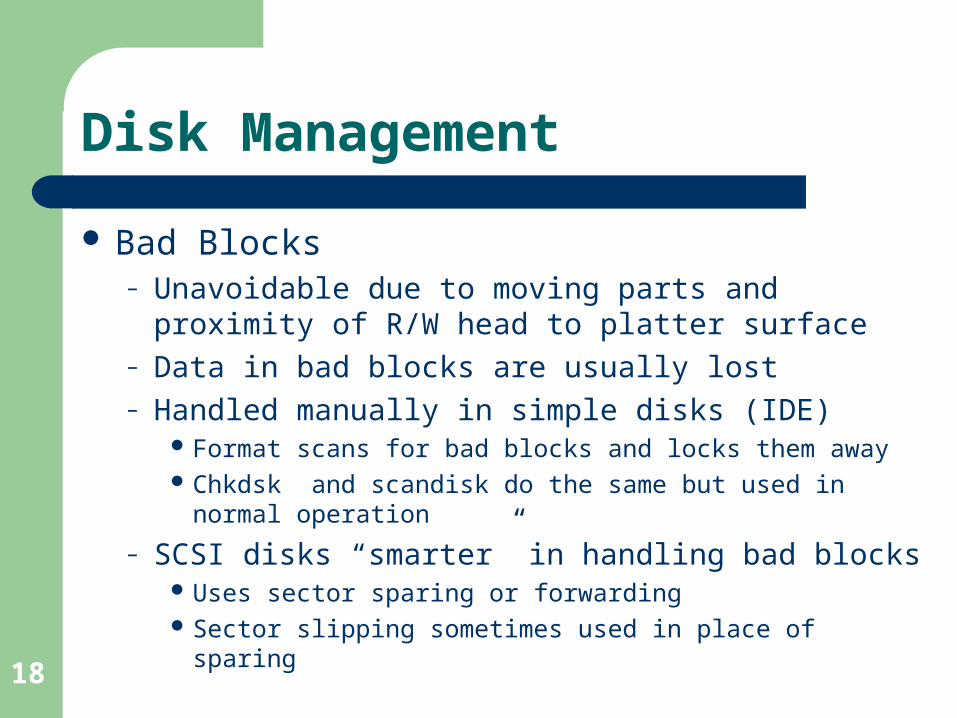
Disk Management
Bad Blocks– Unavoidable due to moving parts and proximity of
R/W head to platter surface– Data in bad blocks are usually lost– Handled manually in simple disks (IDE)
Format scans for bad blocks and locks them away Chkdsk and scandisk do the same but used in normal
operation
– SCSI disks “smarter” in handling bad blocks Uses sector sparing or forwarding Sector slipping sometimes used in place of sparing

19
Swap Space
Goal: provide best throughput for virtual memory system
Swap space use– Varies depending on O/S (e.g. entire process image,
pages pushed out of MM swapped, etc.)– Some O/Ss allow multiple swap spaces– Safer to overestimate than to underestimate size
Swap space location– Part of the file system (Windows)– Separate disk partition (normally raw device, e.g. Unix)

20
RAID Structure
Redundant Arrays of Inexpensive Disks Concept now extended to other devices such as
tapes Redundancy solves problem of reliability
– Duplicate each disk (mirroring/shadowing)
Performance improvement via parallelism– Mirroring doubles read access times– Data striping: splitting data across multiple disks (bit-
level, block-level, sector-level, etc.)

21
RAID Levels
Mirroring: high-reliability but expensive; striping: high-speed but does not improve reliability
RAID levels provide a scheme that combines mirroring and striping– Cost-performance trade-offs (hence, levels)– Example: RAID 0 (block striping but without
mirroring), RAID 1 (mirroring), RAID 0 + 1

22
Disk Attachment
Host-attached storage– May be IDE, SCSI, or RAID
device
Network-attached storage– Provides convenient way to
share pool of storage and data– Consumes network bandwidth– More efficient if Storage Area
Network (SAN) is implemented (using storage rather than networking protocols)

23
Tertiary Storage
Built with removable mediaLow-cost is defining characteristicRemovable disks
– Magnetic (e.g. floppy, zip drives, hot-swappable hard-disks)
– OpticalWORM (Write Once Read Many, e.g. CD-R)Phase-change (e.g. CD-RW)
– Magneto-optical

24
Tertiary Storage
Tapes– Off-line: sits on shelves– Near-line: uses robotic arms -> between off-
line and on-line (e.g. disks)Future technology
– Holographic storage: records holographic photographs on special media
– Micro-electronic mechanical systems (MEMS) -> produces small storage machines

25
Tertiary Storage Performance
SpeedReliabilityCost


