
1. Open windows. 2. DO NOT try to light any appliance. 3 ...€¦ · 2. DO NOT try to light any...
67
WARNING FOR YOUR SAFETY If you smell gas: 1. Open windows. 2. DO NOT try to light any appliance. 3. DO NOT use electrical switches. 4. DO NOT use any telephone in your building. 5. Extinguish any open flame. 6. Leave the building. 7. Immediately call your local gas supplier after leaving the building. Follow the gas supplier’s instructions. 8. If you cannot reach your gas supplier, call the Fire Department. Fire Hazard Keep all flammable objects, liquids and vapors the minimum required clear- ances to combustibles away from heater. Some objects will catch fire or explode when placed close to heater. Failure to follow these instructions can result in death, injury or property damage. WARNING Installation must be done by a contractor qualified in the installation and service of gas-fired heating equipment or your gas supplier. Improper installation, adjustment, alteration, service or maintenance can result in death, injury or property damage. Read the Installation, Operation and Service Manual thoroughly before installing or servicing this equipment. Installer Please take the time to read and understand these instructions prior to any installation. Installer must give a copy of this manual to the owner. Owner Keep this manual in a safe place in order to provide your service technician with necessary information. Roberts-Gordon LLC 1250 William Street P.O. Box 44 Buffalo, New York 14240-0044 Telephone: +1.716.852.4400 Fax: +1.716.852.0854 Toll Free: 800.828.7450 www.robertsgordon.com ©2019 Roberts-Gordon LLC P/N 170101NA Rev . T 10/19 Model BH The Economical Unitary Infrared Heater Installation, Operation & Service Manual BH-40 BH-60 BH-80 BH-100 BH-115 BH-125 BH-140 BH-150 BH-175 BH-200
Transcript of 1. Open windows. 2. DO NOT try to light any appliance. 3 ...€¦ · 2. DO NOT try to light any...

WARNING
FOR YOUR SAFETY
If you smell gas: 1. Open windows.
2. DO NOT try to light any appliance.
3. DO NOT use electrical switches.
4. DO NOT use any telephone in
your building.
5. Extinguish any open flame.
6. Leave the building.
7. Immediately call your local gas
supplier after leaving the building.
Follow the gas supplier’s
instructions.
8. If you cannot reach your gas
supplier, call the Fire Department.
Fire Hazard
Keep all flammable objects, liquids and
vapors the minimum required clear-
ances to combustibles away from
heater.
Some objects will catch fire or explode when placed close to heater.
Failure to follow these instructions can result in death, injury or property damage.
WARNING
Installation must be done by a contractor qualified
in the installation and service of gas-fired heating
equipment or your gas supplier.
Improper installation, adjustment, alteration, service
or maintenance can result in death, injury or
property damage. Read the Installation, Operation
and Service Manual thoroughly before installing or
servicing this equipment.
Installer
Please take the time to read and understand
these instructions prior to any installation.
Installer must give a copy of this manual to the owner.
Owner
Keep this manual in a safe place in order to provide
your service technician with necessary information.
Roberts-Gordon LLC1250 William StreetP.O. Box 44Buffalo, New York 14240-0044Telephone: +1.716.852.4400Fax: +1.716.852.0854Toll Free: 800.828.7450
www.robertsgordon.com©2019 Roberts-Gordon LLC P/N 170101NA Rev. T 10/19
Model BHThe Economical Unitary
Infrared HeaterInstallation, Operation &
Service ManualBH-40
BH-60
BH-80
BH-100
BH-115
BH-125
BH-140
BH-150
BH-175
BH-200

© 2019 Roberts-Gordon LLC
All rights reserved. No part of this work covered by the copyrights herein may be reproduced
or copied in any form or by any means - graphic, electronic, or mechanical, including
photocopying, recording, taping or information storage and retrieval systems - without the
written permission of Roberts-Gordon LLC.
TABLE OF CONTENTSSECTION 1: Heater Safety ...................................................... 1
1.1 Manpower Requirements ............................................. 1
1.2 Safety Labels and Their Placement.............................. 1
1.3 California Proposition 65 .............................................. 1
SECTION 2: Installer Responsibility...................................... 42.1 Wall Tag ....................................................................... 4
2.2 Corrosive Chemicals.................................................... 4
2.3 National Standards and Applicable Codes................... 4
SECTION 3: Clearances to Combustibles............................. 53.1 Required Clearances to Combustibles......................... 5
SECTION 4: National Standards and Applicable Codes.... 104.1 Gas Codes................................................................. 10
4.2 Aircraft Hangars ......................................................... 10
4.3 Public Garages .......................................................... 10
4.4 Electrical .................................................................... 10
4.5 Venting ....................................................................... 10
4.6 High Altitude .............................................................. 10
SECTION 5: Major Components .......................................... 115.1 Standard Parts List .................................................... 13
SECTION 6: Heater Installation............................................ 166.1 Burner Tube Installation ............................................ 20
6.2 Tube Clamp Package Installation.............................. 21
6.3 Coupling and Tube Assembly.................................... 21
6.4 Turbulator Installation ................................................ 23
6.5 Reflector Installation .................................................. 24
6.6 Burner Installation...................................................... 26
SECTION 7: Optional Heater Accessories .......................... 277.1 U-Tube Configuration.................................................. 27
7.2 Elbow Package Configuration..................................... 30
7.3 Reflector Side Extension ............................................ 33
7.4 Lower Clearance Shield Installation ........................... 34
7.5 Two-Foot Decorative Grille Installation ....................... 34
7.6 Protective Grille Installation ........................................ 36
SECTION 8: Venting .............................................................. 378.1 Venting ....................................................................... 37
8.2 Unvented Operation................................................... 38
8.3 Horizontal Venting...................................................... 38
8.4 Vertical Venting .......................................................... 38
8.5 Unvented Operation Tube Termination....................... 38
8.6 Length Requirements ................................................ 38
8.7 Vent Material Recommendations ............................... 38
8.8 Horizontal Ventilation 4'' (10 cm) Pipe........................ 39
8.9 Vertical Ventilation 4'' (10 cm) Pipe ............................ 39
8.10 Common Side Wall Venting...................................... 40
8.11 Common Vertical Venting ........................................ 41
8.12 Outside Combustion Air Supply ............................... 42
SECTION 9: Gas Piping........................................................ 45SECTION 10: Wiring .............................................................. 47
10.1 Line Voltage Thermostat Wiring ............................... 47
10.2 Low Voltage Thermostat Wiring ............................... 48
10.3 Internal Wiring.......................................................... 49
10.4 Ladder Diagram....................................................... 50
10.5 Electrical Connection to the Burner ......................... 50
SECTION 11: Operation and Maintenance.......................... 5111.1 Sequence of Operation ............................................ 51
11.2 To Shut Off Heater .................................................... 51
11.3 To Start Heater ......................................................... 51
11.4 Pre-Season Maintenance and Annual Inspection..... 51
11.5 Maintenance Checklist ............................................. 52
SECTION 12: Troubleshooting ............................................. 5412.1 Troubleshooting Flow Chart ..................................... 55
12.2 Manifold Gas Pressure Setting ................................ 57
SECTION 13: Replacement Parts ........................................ 58SECTION 14: General Specifications .................................. 61
14.1 Material Specifications............................................. 61
14.2 Heater Specifications............................................... 61
14.3 Suspension Specifications....................................... 61
14.4 Controls Specifications ............................................ 61
SECTION 15: The ROBERTS GORDON® COMPACT™ BH Warranty................................................... 63
Printed in U.S.A.

SECTION 1: 9HEATER SAFETY
1 of 63
SECTION 1: 9HEATER SAFETYYour Safety is Important to Us!This symbol is used throughout the manual to notify you of possible fire, electrical or burn hazards. Please pay special attention when reading and following the warnings in these
sections.
Installation, service and annual inspection of heater must be done by a contractor qualified in the installation and service of gas-fired heating equipment.
Read this manual carefully before installation, operation or service of this equipment.
This heater is designed for heating nonresidential indoor spaces. Do not install in residential spaces. This heater is not certified to meet the requirements of NFPA30A-2012 Section 7.6.6. (maximum tube temperature of 750 °F (399 °C)). Do not install this heater in facilities where compressed natural gas (CNG) or liquid natural gas (LNG) are present. These instructions, the layout drawing, local codes and ordinances, and applicable standards that apply to gas piping, electrical wiring, venting, etc. must be thoroughly understood before proceeding with the installation.Protective gear is to be worn during installation, operation and service in accordance to the Occupational Safety and Hazard Administration (OSHA). Gear must be in accordance to NFPA 70E, latest revision when working with electrical components. Thin sheet metal parts have sharp edges. To prevent injury, the use of work gloves is recommended. The use of gloves will also prevent the transfer of body oils from the hands to the surface of the reflector.
Before installation, check that local distribution conditions, nature of gas and pressure, and adjustment of the appliance are compatible.
This heater must be applied and operated under the general concepts of reasonable use and installed using best building practices.This appliance is not intended for use by persons (including children) with reduced physical, sensory or mental capabilities, or lack of experience and knowledge, unless they have been given supervision or instruction concerning use of the appliance by a person responsible for their safety. Children should be supervised to ensure that they do no play with the appliance.
For additional copies of the Installation, Operation and Service Manual, please contact Roberts-Gordon LLC.
1.1 Manpower RequirementsTo prevent personal injury and damage to the heater, two persons will be required for installation.
1.2 Safety Labels and Their PlacementProduct safety signs or labels should be replaced by the product user when they are no longer legible. Please contact Roberts-Gordon LLC or your ROBERTS GORDON® independent distributor to obtain replacement signs or labels. See Page 2, Figure 1 through Page 3, Figure 2.
1.3 California Proposition 65In accordance with California Proposition 65 requirements, a warning label must be placed in a highly visible location on the outside of the equipment (i.e., near equipment’s serial plate). See label placement drawing on Page 3, Figure 2 for label location. Avoid placing label on areas with extreme heat, cold, corrosive chemicals or other elements. To order additional labels, please contact Roberts-Gordon LLC or your ROBERTS GORDON® independent distributor.

BH-SERIES INSTALLATION, OPERATION AND SERVICE MANUAL
2 of 63
FIGURE 1: Top and Bottom Panel Label Placement
Description Part NumberLogo Label 91013222Vent Length Label 91039500Gas Connection Label 91018123

SECTION 1: 9HEATER SAFETY
3 of 63
FIGURE 2: Side and Back Panel Label Placement
96 244
12 31 10 26 85 216 79 201
18 46 102 259
102 259
102 259
Level
droit
Level
droit
E
96 244
12 31 10 26 85 216 79 201
18 46 102 259
102 259
102 259
Level
droit
Level
droit
E
Description Part NumberRating Plate Label 91010401Lighting Instruction Plate Label 91029602Wiring Label 91030301-NAClearances to Combustibles Label 91013412Proposition 65 Label 91070016

BH-SERIES INSTALLATION, OPERATION AND SERVICE MANUAL
4 of 63
SECTION 2: INSTALLER RESPONSIBILITYThe installer is responsible for the following:
• To install the heater, as well as the gas and electrical supplies, in accordance with applicable specifications and codes. Roberts-Gordon LLC recommends the installer contact a local Building Inspector or Fire Marshal for guidance.
• To use the information given in a layout drawing and in the manual together with the cited codes and regulations to perform the installation.
• To install the heater in accordance with the clearances to combustibles.
• To furnish all needed materials not furnished as standard equipment.
• To plan location of supports.
• To provide access on all sides for burner servicing and removal.
• To provide the owner with a copy of this Installation, Operation and Service Manual.
• To never use heater as a support for a ladder or other access equipment and never hang or suspend anything from heater.
• To ensure there is adequate air circulation around the heater and to supply air for combustion, ventilation and distribution in accordance with local codes.
• To safely and adequately install heater using materials with a minimal working load of 75 lbs (33 kg).
• To ensure the heater is placed in an approved application.
2.1 Wall TagA laminated wall tag is available for the heater as a permanent reminder of the safety instructions and the importance of the required clearances to combustibles. Please contact Roberts-Gordon LLC or your ROBERTS GORDON® independent distributor to obtain the wall tag. Affix the tag by peeling off the backing of the adhesive strips on the rear surface and position the tag on a wall near the heater (e.g. thermostat or ROBERTS GORDON® Controller).A copy of the wall tag (P/N 91037912) is illustrated on the back cover. For an immediate solution, you may affix this copy on the wall near the heater.Know your model number and installed configuration. Model number and installed configuration are found on the burner and in the Installation, Operation and Service Manual. See Page 6, Figure 3 through Page 9, Figure 12. Write the proper clearance dimensions in
permanent ink according to your model number and configuration in the open spaces on the tag.
2.2 Corrosive Chemicals
Roberts-Gordon LLC cannot be responsible for ensuring that all appropriate safety measures are undertaken prior to installation; this is entirely the responsibility of the installer. It is essential that the contractor, the sub-contractor, or the owner identifies the presence of combustible materials, corrosive chemicals or halogenated hydrocarbons* anywhere in the premises.
* Halogenated Hydrocarbons are a family of chemical compounds characterized by the presence of halogen elements (fluorine, chlorine, bromine, etc.). These compounds are frequently used in refrigerants, cleaning agents, solvents, etc. If these compounds enter the air supply of the burner, the life span of the heater components will be greatly reduced. An outside air supply must be provided to the burners whenever the presence of these compounds is suspected. Warranty will be invalid if the heater is exposed to halogenated hydrocarbons.
2.3 National Standards and Applicable CodesAll appliances must be installed in accordance with the latest revision of the applicable standards and national codes. This refers also to the electric, gas and venting installation. Note: Additional standards for installations in public garages, aircraft hangars, etc. may be applicable.
CAUTION
Product Damage Hazard
Do not use heater in area containing corrosive chemicals.
Refer to appropriate Material Safety Data Sheets (MSDS).
Failure to follow these instructions can result in product damage.

SECTION 3: CLEARANCES TO COMBUSTIBLES
5 of 63
SECTION 3: CLEARANCES TO COMBUSTIBLES3.1 Required Clearances to CombustiblesClearances are the required distances that combustible objects must be away from the heater to prevent serious fire hazards. Combustibles are materials that may catch on fire and include common items such as wood, paper, rubber, fabric, etc. Maintain clearances to combustibles at all times for safety.Clearances for all heater models are located on the burner of the heater and on Page 6, Figure 3 through Page 9, Figure 12 in this manual. Check the clearances on each burner for the model heater being installed to make sure the product is suitable for your application and the clearances are maintained. Read and follow the safety guidelines below:
• Keep gasoline or other combustible materials including flammable objects, liquids, dust or vapors away from this heater or any other appliance.
• The stated clearances to combustibles represents a surface temperature of 90 °F (32 °C) above room temperature. Building materials with a low heat tolerance (such as plastics, vinyl siding, canvas, tri-ply, etc) may be subject to degradation at lower temperatures. It is the installer’s responsibility to assure that adjacent materials are protected from degradation.
• Maintain clearances from heat sensitive equipment and workstations.
• Maintain clearances from vehicles parked below the heater.
• Maintain clearances from swinging and overhead doors, overhead cranes, vehicle lifts, partitions, storage racks, hoists, building construction, etc.
• In locations used for the storage of combustible materials, signs must be posted to specify the maximum permissible stacking height to maintain required clearances from the heater to the combustibles. Signs must be posted adjacent to the heater thermostat. In the absence of a thermostat, signs must be posted in a conspicuous location.
• Consult local Fire Marshal, Fire Insurance Carrier or other authorities for approval of proposed installation when there is a possibility of exposure to combustible airborne materials or vapors.
• Hang heater in accordance to the minimum suspension requirements on Page 17, Figure 15.
• If the radiant tubes must pass through the building structure, be sure that adequate sleeving and fire stop is installed to prevent scorching and/or fire hazard.
WARNING
Fire Hazard
Keep all flammable objects, liquids and vapors the minimum required clearances to combustibles away from heater.
Some objects will catch fire or explode when placed close to heater.
Failure to follow these instructions can result in death, injury or property damage.

BH-SERIES INSTALLATION, OPERATION AND SERVICE MANUAL
6 of 63
NOTE: 1. All dimensions are from the surfaces of all tubes, couplings and elbows.2. Clearances B, C and D can be reduced by 50% after 25' (7.5 m) of tubing downstream from where the burner and burner tube connect.
FIGURE 3: Level Reflector(inches) (centimeters)
Model A B C D A B C D
BH-40 6 27 52 27 16 69 133 69
BH-60 6 35 62 35 16 89 158 89
BH-80 6 38 65 38 16 97 166 97
BH-100 6 40 70 40 16 102 178 102
BH-115/125 6 46 76 46 16 117 194 117
BH-140/150 6 50 79 50 16 127 201 127
BH-175 8 52 82 52 21 133 209 133
BH-200 8 52 96 52 21 133 244 133
FIGURE 4: One Side Reflector(inches) (centimeters)
Model A B C D A B C D
BH-40 6 9 52 44 16 23 133 112
BH-60 6 9 62 47 16 23 158 120
BH-80 6 9 69 54 16 23 176 138
BH-100 6 9 76 59 16 23 194 150
BH-115/125 6 9 82 65 16 23 209 166
BH-140/150 6 9 85 69 16 23 216 176
BH-175 8 9 88 73 21 23 224 186
BH-200 8 18 102 73 21 46 260 186
�� �
�
FIGURE 5: Two Side Reflectors(inches) (centimeters)
Model A B C D A B C D
BH-40 6 15 52 15 16 39 133 39
BH-60 6 23 65 23 16 59 166 59
BH-80 6 25 71 25 16 64 181 64
BH-100 6 27 77 27 16 69 196 69
BH-115/125 6 32 83 32 16 82 211 82
BH-140/150 6 35 87 35 16 89 221 89
BH-175 8 40 91 40 21 102 232 102
BH-200 8 40 102 40 21 102 260 102
�� �
�

SECTION 3: CLEARANCES TO COMBUSTIBLES
7 of 63
NOTE: 1. All dimensions are from the surfaces of all tubes, couplings and elbows.2. Clearances B, C and D can be reduced by 50% after 25' (7.5 m) of tubing downstream from where the burner and burner tube connect.
FIGURE 6: 45° Tilt Reflector(inches) (centimeters)
Model A B C D A B C D
BH-40 8 8 50 46 21 21 127 117
BH-60 8 8 59 54 21 21 150 138
BH-80 8 8 65 60 21 21 166 153
BH-100 10 8 73 64 26 21 186 163
BH-115/125 10 8 77 69 26 21 196 176
BH-140/150 12 8 83 74 31 21 211 188
BH-175 12 8 85 79 31 21 216 201
BH-200 12 10 85 79 31 26 216 201
FIGURE 7: U-Tube, Standard Reflector(inches) (centimeters)
Model A B C D A B C D
BH-40 - UNAPPROVED - - UNAPPROVED -
BH-60 6 35 62 30 16 89 158 77
BH-80 6 38 68 37 16 97 173 94
BH-100 6 40 75 39 16 102 191 100
BH-115/125 6 46 78 43 16 117 199 110
BH-140/150 6 50 83 47 16 127 211 120
BH-175 8 54 87 51 21 138 221 130
BH-200 8 54 102 51 21 138 260 130
� ��
�
FIGURE 8: U-Tube, 45°(inches) (centimeters)
Model A B C D A B C D
BH-40 - UNAPPROVED - - UNAPPROVED -
BH-60 8 8 59 42 21 21 150 107
BH-80 8 8 65 46 21 21 166 117
BH-100 8 8 73 52 21 21 186 133
BH-115/125 8 8 77 61 21 21 196 155
BH-140/150 8 8 83 66 21 21 211 168
BH-175 8 8 85 70 21 21 216 178
BH-200 8 8 85 70 21 21 216 178
�
��
�

BH-SERIES INSTALLATION, OPERATION AND SERVICE MANUAL
8 of 63
NOTE: 1. All dimensions are from the surfaces of all tubes, couplings and elbows.2. Clearances B, C and D can be reduced by 50% after 25' (7.5 m) of tubing downstream from where the burner and burner tube connect.
*When installed in the first 10' (3 m).
FIGURE 9: U-Tube, Opposite 45° Reflector(inches) (centimeters)
Model A B C D A B C D
BH-40 - UNAPPROVED - - UNAPPROVED -
BH-60 8 54 59 22 21 138 150 56
BH-80 8 60 65 22 21 153 166 56
BH-100 10 64 73 22 26 163 186 56
BH-115/125 10 70 77 22 26 178 196 56
BH-140/150 12 74 83 22 31 188 211 56
BH-175 12 76 85 22 31 194 216 56
BH-200 12 76 85 22 31 194 216 56
�
�
� �
FIGURE 10: 2-Foot Deco Grille and Protective Grille(inches) (centimeters)
Model A B C D A B C D
BH-40 6 27 52 27 16 69 133 69
BH-60 6 35 62 35 16 89 158 89
BH-80 6 38 65 38 16 97 166 97
BH-100 6 40 70 40 16 102 178 102
BH-115/125 6 46 76 46 16 117 194 117
BH-140/150 6 50 79 50 16 127 201 127
BH-175 8 52 82 52 21 133 209 133
BH-200 8 52 96 52 21 133 244 133
�
� �
�
FIGURE 11: Lower Clearance Shield*(inches) (centimeters)
Model A B C D A B C D
BH-40 6 34 27 34 16 87 69 87
BH-60 6 39 33 39 16 100 84 100
BH-80 6 40 38 40 16 102 97 102
BH-100 6 50 44 50 16 127 112 127
BH-115/125 6 54 48 54 16 138 122 138
BH-140/150 6 55 50 55 16 140 127 140
BH-175/200 - UNAPPROVED - - UNAPPROVED -
�� �
�

SECTION 3: CLEARANCES TO COMBUSTIBLES
9 of 63
NOTE: 1. All dimensions are from the surfaces of all tubes, couplings and elbows.2. Clearances B, C and D can be reduced by 50% after 25' (7.5 m) of tubing downstream from where the burner and burner tube connect.
FIGURE 12: Venting(inches) (centimeters)
Model A E F A E F
BH-40 14 18 18 36 46 46
BH-60 14 18 18 36 46 46
BH-80 20 24 18 51 61 46
BH-100 20 24 18 51 61 46
BH-115/125 20 24 18 51 61 46
BH-140/150 20 30 18 51 77 46
BH-175/200 20 30 18 51 77 46
������ ����
�������
��������
������
� �
�
BH-SERIES INSTALLATION, OPERATION AND SERVICE MANUAL
10 of 63
SECTION 4: NATIONAL STANDARDS AND APPLICABLE CODES
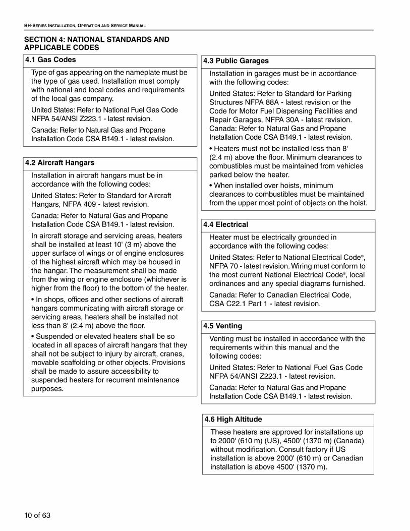
4.1 Gas Codes
Type of gas appearing on the nameplate must be the type of gas used. Installation must comply with national and local codes and requirements of the local gas company.
United States: Refer to National Fuel Gas Code NFPA 54/ANSI Z223.1 - latest revision.
Canada: Refer to Natural Gas and Propane Installation Code CSA B149.1 - latest revision.
4.2 Aircraft Hangars
Installation in aircraft hangars must be in accordance with the following codes:
United States: Refer to Standard for Aircraft Hangars, NFPA 409 - latest revision.
Canada: Refer to Natural Gas and Propane Installation Code CSA B149.1 - latest revision.
In aircraft storage and servicing areas, heaters shall be installed at least 10' (3 m) above the upper surface of wings or of engine enclosures of the highest aircraft which may be housed in the hangar. The measurement shall be made from the wing or engine enclosure (whichever is higher from the floor) to the bottom of the heater.
• In shops, offices and other sections of aircraft hangars communicating with aircraft storage or servicing areas, heaters shall be installed not less than 8' (2.4 m) above the floor.
• Suspended or elevated heaters shall be so located in all spaces of aircraft hangars that they shall not be subject to injury by aircraft, cranes, movable scaffolding or other objects. Provisions shall be made to assure accessibility to suspended heaters for recurrent maintenance purposes.
4.3 Public Garages
Installation in garages must be in accordance with the following codes:
United States: Refer to Standard for Parking Structures NFPA 88A - latest revision or the Code for Motor Fuel Dispensing Facilities and Repair Garages, NFPA 30A - latest revision. Canada: Refer to Natural Gas and Propane Installation Code CSA B149.1 - latest revision.
• Heaters must not be installed less than 8' (2.4 m) above the floor. Minimum clearances to combustibles must be maintained from vehicles parked below the heater.
• When installed over hoists, minimum clearances to combustibles must be maintained from the upper most point of objects on the hoist.
4.4 Electrical
Heater must be electrically grounded in accordance with the following codes:
United States: Refer to National Electrical Code®, NFPA 70 - latest revision. Wiring must conform to the most current National Electrical Code®, local ordinances and any special diagrams furnished.
Canada: Refer to Canadian Electrical Code, CSA C22.1 Part 1 - latest revision.
4.5 Venting
Venting must be installed in accordance with the requirements within this manual and the following codes:
United States: Refer to National Fuel Gas Code NFPA 54/ANSI Z223.1 - latest revision.
Canada: Refer to Natural Gas and Propane Installation Code CSA B149.1 - latest revision.
4.6 High Altitude
These heaters are approved for installations up to 2000' (610 m) (US), 4500' (1370 m) (Canada) without modification. Consult factory if US installation is above 2000' (610 m) or Canadian installation is above 4500' (1370 m).

SECTION 5: MAJOR COMPONENTS
11 of 63
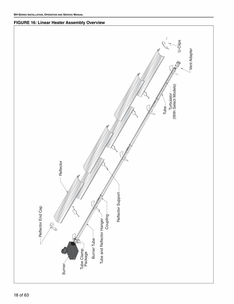
SECTION 5: MAJOR COMPONENTS FIGURE 13: Major Component Descriptions - Standard Reflector
Burner with Tube GasketMust be installed with the flame observation window facing down.
Standard Reflector (Aluminum or Stainless Steel)Alternate overlap as shown on overview and on Page 19, Figure 17. Minimum overlap is 6'' (16 cm).
Tube and Reflector Hanger with Clamp PackagePosition this hanger no more than 4” (10 cm) away from the burner.
Coupling Assembly with Lock
Reflector End CapPunch out center section to accommodate tube.
Tube and Reflector HangerSuspend system from these hangers.
Flex Gas Line with Shut Off Cock
TubeHot rolled or heat treated aluminized tube supplied in 10' (3 m) lengths.
Burner TubeSupplied in 10' (3 m) lengths. Burner tube is always the first tube after the burner.
Reflector Support Strap & Wire Form
TurbulatorInstall turbulator as specified in the “Turbulator Installation” chart. See Page 21, Step 6.4. Turbulator is not required on the BH-125/150/175/200.
Vent Adapter

BH-SERIES INSTALLATION, OPERATION AND SERVICE MANUAL
12 of 63
FIGURE 14: Major Component Descriptions - High Efficiency Reflector
Burner with Tube GasketMust be installed with the flame observation window facing down.
Reflector (Aluminum)Alternate overlap as shown on overview and on Page 19, Figure 17. Minimum overlap is 6'' (16 cm).
Tube and Reflector Hanger with Clamp Package-EFPosition this hanger no more than 4” (10 cm) away from the burner.
Coupling Assembly with Lock
Reflector End Cap-EFPunch out center section to accommodate tube.
Tube and Reflector Hanger-EFSuspend system from these hangers.
Flex Gas Line with Shut Off Cock
TubeHot rolled or heat treated aluminized tube supplied in 10' (3 m) lengths.
Burner TubeSupplied in 10' (3 m) lengths. Burner tube is always the first tube after the burner.
Reflector Support Strap & Wire Form-EF
TurbulatorInstall turbulator as specified in the “Turbulator Installation” chart. See Page 21, Step 6.4. Turbulator is not required on the BH-125/150/175/200.
Vent Adapter

SECTION 5: MAJOR COMPONENTS
13 of 63
5.1 Standard Parts List
*Canadian models: Rubber (Type 1) Gas Hoses available as an accessory. See Page 45.
Table 1: Contents of BH-Series Burner Carton
Part No. Description BH-40 BH-60 BH-80 BH-100 BH-115 BH-125 BH-140 BH-150 BH-175 BH-200
071XXXXX Burner (Rate and Fuel Varies) 1 1 1 1 1 1 1 1 1 1
90709700 Blower Assembly with Cord 1 1 1 1 1 1 1 1 1 1
02568200 Gasket (Burner to Burner Tube) 1 1 1 1 1 1 1 1 1 1
90709801 Gasket (Blower to Burner) 1 1 1 1 1 1 1 1 1 1
170101NA Installation, Operation and Service Manual 1 1 1 1 1 1 1 1 1 1
91201708 Pipe Nipple (Black) 1/2" NPT x 4" 1 1 1 1 1 1 1 1 1 1
94273914 Hex Head Bolts 5/16" - 18 Rolok 4 4 4 4 4 4 4 4 4 4
96411600 Split Lock Washer 4 4 4 4 4 4 4 4 4 4
*91412200 Flexible Stainless Steel Gas Hose, 1/2" NPT (US Models Only) 1 1 1 1 1 1 - - - -
*91412204 Flexible Stainless Steel Gas Hose, 3/4" NPT (US Models Only) - - - - - - 1 1 1 1
91907302 S-Hooks 2 2 2 2 2 2 2 2 2 2
91911700 Outside Air Collar 1 1 1 1 1 1 1 1 1 1
94118106 #8 x 3/8 Hex Washer Head (for Outside Air Collar) 3 3 3 3 3 3 3 3 3 3
92311800 Keps Nut 4 4 4 4 4 4 4 4 4 4
03051501 Turbulator Adapter 1 1 1 1 1 - 1 - - -
03051502 Turbulator 2.5' (76 cm), Aluminized Steel 2 4 4 1 3 - 1 - - -
03051505 Turbulator 2.5' (76 cm), Stainless Steel 1 - - - - - - - - -
Table 2: Contents of Standard Core and Extension Packages
Core Packages Extension Packages
Hot Rolled Aluminized Hot Rolled Aluminized
Part No. Description 20'(6m)
30'(9m)
40'(12m)
10'(3m)
20'(6m)
30'(9m)
40'(12m)
10'(3m)
20'(6m)
30'(9m)
40'(12m)
10'(3m)
20'(6m)
30'(9m)
40'(12m)
91409300 Tube, Hot Rolled Steel, 10' (3 m) 1 2 3 - - - - 1 2 3 4 - - - -
91409408 Tube, HT Aluminized, 10' (3 m) - - - - 1 2 3 - - - - 1 2 3 4
03051101 Burner Tube, ALUMI-THERM® Steel, 10' (3 m) - 1 1 - - 1 1 - - - - - - - -
03051601 Burner Tube, HT ALUMI-THERM® Steel, 10' (3 m) 1 - - 1 1 - - - - - - - - - -
01312700 Coupling Assembly 1 2 3 - 1 2 3 1 2 3 4 1 2 3 4
02750303 Standard Reflector, 8' (3.5 m) 3 4 6 2 3 4 6 2 3 4 6 2 3 4 6
02750800 End Cap 2 2 2 2 2 2 2 - - - - - - - -
03090100 Tube and Reflector Hanger 3 4 5 2 3 4 5 1 2 3 4 1 2 3 4
91907302 S-Hook 3 4 5 2 3 4 5 1 2 3 4 1 2 3 4
03050010 Reflector Support Package (Strap, Wire Form, Screws) 2 3 5 1 2 3 5 2 3 4 6 2 3 4 6
91107720 U-Clip Package 1 1 1 1 1 1 1 1 1 1 1 1 1 1 1
90502701 Vent Adapter 1 1 1 1 1 1 1 - - - - - - - -
01318901 Tube Clamp Package 1 1 1 1 1 1 1 - - - - - - - -
Part Number
CP20
HRS
CP30
HRS
CP40
HRS
CP10
ALUM
CP20
ALUM
CP30
ALUM
CP40
ALUM
EXP1
0HRS
EXP2
0HRS
EXP3
0HRS
EXP4
0HRS
EXP1
0ALU
M
EXP2
0ALU
M
EXP3
0ALU
M
EXP4
0ALU
M
BH-SERIES INSTALLATION, OPERATION AND SERVICE MANUAL
14 of 63
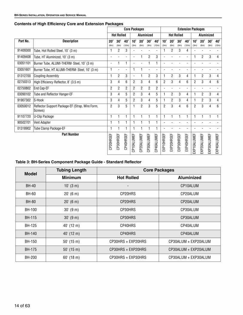
Contents of High Efficiency Core and Extension PackagesCore Packages Extension Packages
Hot Rolled Aluminized Hot Rolled Aluminized
Part No. Description 20'(6m)
30'(9m)
40'(12m)
10'(3m)
20'(6m)
30'(9m)
40'(12m)
10'(3m)
20'(6m)
30'(9m)
40'(12m)
10'(3m)
20'(6m)
30'(9m)
40'(12m)
91409300 Tube, Hot Rolled Steel, 10' (3 m) 1 2 3 - - - - 1 2 3 4 - - - -
91409408 Tube, HT Aluminized, 10' (3 m) - - - - 1 2 3 - - - - 1 2 3 4
03051101 Burner Tube, ALUMI-THERM® Steel, 10' (3 m) - 1 1 - - 1 1 - - - - - - - -
03051601 Burner Tube, HT ALUMI-THERM® Steel, 10' (3 m) 1 - - 1 1 - - - - - - - - - -
01312700 Coupling Assembly 1 2 3 - 1 2 3 1 2 3 4 1 2 3 4
02750313 High Efficiency Reflector, 8' (3.5 m) 3 4 6 2 3 4 6 2 3 4 6 2 3 4 6
02750802 End Cap-EF 2 2 2 2 2 2 2 - - - - - - - -
03090102 Tube and Reflector Hanger-EF 3 4 5 2 3 4 5 1 2 3 4 1 2 3 4
91907302 S-Hook 3 4 5 2 3 4 5 1 2 3 4 1 2 3 4
03050012 Reflector Support Package-EF (Strap, Wire Form, Screws)
2 3 5 1 2 3 5 2 3 4 6 2 3 4 6
91107720 U-Clip Package 1 1 1 1 1 1 1 1 1 1 1 1 1 1 1
90502701 Vent Adapter 1 1 1 1 1 1 1 - - - - - - - -
01318902 Tube Clamp Package-EF 1 1 1 1 1 1 1 - - - - - - - -
Part Number
CP20
HRSE
F
CP30
HRSE
F
CP40
HRSE
F
CP10
ALUM
EF
CP20
ALUM
EF
CP30
ALUM
EF
CP40
ALUM
EF
EXP1
0HRS
EF
EXP2
0HRS
EF
EXP3
0HRS
EF
EXP4
0HRS
EF
EXP1
0ALU
MEF
EXP2
0ALU
MEF
EXP3
0ALU
MEF
EXP4
0ALU
MEF
Table 3: BH-Series Component Package Guide - Standard Reflector
ModelTubing Length Core Packages
Minimum Hot Rolled Aluminized
BH-40 10' (3 m) - CP10ALUM
BH-60 20' (6 m) CP20HRS CP20ALUM
BH-80 20' (6 m) CP20HRS CP20ALUM
BH-100 30' (9 m) CP30HRS CP30ALUM
BH-115 30' (9 m) CP30HRS CP30ALUM
BH-125 40' (12 m) CP40HRS CP40ALUM
BH-140 40' (12 m) CP40HRS CP40ALUM
BH-150 50' (15 m) CP30HRS + EXP20HRS CP30ALUM + EXP20ALUM
BH-175 50' (15 m) CP30HRS + EXP20HRS CP30ALUM + EXP20ALUM
BH-200 60' (18 m) CP30HRS + EXP30HRS CP30ALUM + EXP30ALUM

SECTION 5: MAJOR COMPONENTS
15 of 63
Table 4: BH-Series Component Package Guide - High Efficiency Reflector
Although not recommended, additional tube lengths may be added to the heater. Tubing must be hot-rolled steel, aluminized (heat-treated) or porcelain coated. Additional tube lengths beyond the specified minimum tubing length are considered vent pipe for length determination. Maximum vent length allowed is 45' (13.7 m) total.
ModelTubing Length Core Packages
Minimum Hot Rolled Aluminized
BH-40 10' (3 m) - CP10ALUMEF
BH-60 20' (6 m) CP20HRSEF CP20ALUMEF
BH-80 20' (6 m) CP20HRSEF CP20ALUMEF
BH-100 30' (9 m) CP30HRSEF CP30ALUMEF
BH-115 30' (9 m) CP30HRSEF CP30ALUMEF
BH-125 40' (12 m) CP40HRSEF CP40ALUMEF
BH-140 40' (12 m) CP40HRSEF CP40ALUMEF
BH-150 50' (15 m) CP30HRSEF + EXP20HRSEF CP30ALUMEF+ EXP20ALUMEF
BH-175 50' (15 m) CP30HRSEF + EXP20HRSEF CP30ALUMEF + EXP20ALUMEF
BH-200 60' (18 m) CP30HRSEF + EXP30HRSEF CP30ALUMEF + EXP30ALUMEF

BH-SERIES INSTALLATION, OPERATION AND SERVICE MANUAL
16 of 63
SECTION 6: HEATER INSTALLATION
To ensure your safety and comply with the terms of the warranty, all units must be installed in accordance with these instructions.The gas or the electrical supply lines must not be used to support the heater.Do not locate the gas or electric supply lines directly over the path of the flue products from the heater.The heater must be installed in a location that it is readily accessible for servicing.The heaters must be installed in accordance with clearances to combustibles as indicated on the rating plate and in this instruction manual.The minimum and maximum gas inlet pressures must be maintained as indicated on the rating plate.Typical installation configurations are shown on Page 17, Figure 15.
Expansion and contraction of the tube dictates that the minimum suspension lengths must be maintained. See table on Page 17, Figure 15.WARNING
Severe Injury Hazard
Secure burner to burner tube with nuts and lockwashers.
Hang heater with materials with a minimum working load of 75 lbs (33 kg).
Failure to follow these instructions can result in death, injury or property damage.
WARNING
Cut/Pinch Hazard
Wear protective gear during installation, operation and service.
Edges are sharp.
Failure to follow these instructions can result in injury.

SECTION 6: HEATER INSTALLATION
17 of 63
FIGURE 15: Critical Hanger Placement
NOTE: Suspension material provided by others.
Description Part NumberS-Hook 91907302Tube/Reflector Hanger 0309010X
Run Length Typical Expansion Minimum “X” Length10' (3 m) - 50' (15.2 m) ±1" (3 cm) 12" (30.5 cm)
51' (15.5 m) - 60' (18.3 m) ±2" (5 cm) 18" (45.7 cm)61' (18.6 m) - 80' (24.4 m) ±3" (8 cm) 24" (61 cm)
BH-SERIES INSTALLATION, OPERATION AND SERVICE MANUAL
18 of 63
FIGURE 16: Linear Heater Assembly Overview

SECTION 6: HEATER INSTALLATION
19 of 63
FIGURE 17: Linear Heater Layout Overview
� � �������� ��������������������������
� � �������� �����������������
� � �������� �����������������
� � !�����"�� ���������������������
� �� �#!���� ������������������������
� �� ��"�������� �������������
� �� ������$��� �������������
%����&������
'�����
(��������
)���
)���*(��������+�����
,��������&������-
�������
��
�
�
���
� �
�
��
�
� �
�
�
���
� �
�
� �
���
� �
�
� � �
�#!���� �)����.�����
�#!��"��� �)����.�����
#!��/"��� �)����.�����
�#!����"��� �)����.�����
�#!����"��� �)����.�����

BH-SERIES INSTALLATION, OPERATION AND SERVICE MANUAL
20 of 63
FIGURE 18: Linear Heater Layout Overview (Continued)
Step 6.1 Burner Tube Installation
���
� �
�
� � � �
���
� �
�
� � � � �
���
� �
�
� � � � � �
#!���$"�� �)����.�����
#!����"��� �)����.�����
$#!����"��� �)����.�����
!���0��!���/����0������
����)��������1��������������������������*�������� �����#!���� ����-�����������"
23+��4
'������)���
+�����
5������������������������������������"
6����������������������������������������"
Description Part NumberBurner Tube 03051XXXS-Hook 91907302Tube/Reflector Hanger 0309010X

SECTION 6: HEATER INSTALLATION
21 of 63
Step 6.2 Tube Clamp Package Installation
Step 6.3 Coupling and Tube Assembly
'���)����,����
7���6�����
8���)��1�����#���*���"��8�
Description Part NumberTube Clamp Package 0131890X
A Close coupling and slide opposite end into tab. Position tab underneath guide rail.
B Insert wide end of slide bar/coupling lock into guide rail on opposite end of tabs. Slide the slide bar/coupling lock up the guide rail until snug (approximately 3" (8 cm) to 4" (10 cm)).
C Insert tubes into coupling until end of each tube rests against internal pins.
D Strike slide bar/coupling lock with mallet or hammer until tight.
Description Part NumberCoupling 01329600Slide Bar/Coupling Lock 01329700Tube 91409XXX

BH-SERIES INSTALLATION, OPERATION AND SERVICE MANUAL
22 of 63
Step 6.3.1 Coupling and Tube Assembly (Continued)
Step 6.3.2 Coupling and Tube Assembly (Continued)
• Repeat Step 6.3 A - D until all tubes are assembled. See Page 22, Step 6.3.2.
Tighten slide bar as shown below.
10' ± 1'(3 m ± .25 m)
Total OverallTube Length
7' 6" ± 1'(2.3 m ± .25 m)
ModelTube Length
Minimum BH-40 10' (3 m)BH-60 20' (6 m)BH-80 20' (6 m)BH-100 30' (9 m)BH-115 30' (9 m)BH-125 40' (12 m)BH-140 40' (12 m)BH-150 50' (15 m)BH-175 50' (15 m)BH-200 60' (18 m)

SECTION 6: HEATER INSTALLATION
23 of 63
Step 6.4 Turbulator Installation
Description Part NumberTurbulator Adapter 2.5' (76.2 cm) 03051503Turbulator Section 2' (61 cm) 03051504Turbulator Section 2.5' (76.2 cm) (Stainless) 03051505Tube 91409XXX
Install turbulator as specified in the “Turbulator Installation” chart below. Turbulator is not required on the BH-125/150/175/200.
Turbulator InstallationModel Tube SectionBH-40 1st 10' (3 m) SectionBH-60 2nd 10' (3 m) SectionBH-80 2nd 10' (3 m) SectionBH-100 3rd 10' (3 m) SectionBH-115 3rd 10' (3 m) SectionBH-125 N/ABH-140 4th 10' (3 m) SectionBH-150 N/ABH-175 N/ABH-200 N/A
Turbulator section 2.5' (76.2 cm) (stainless) used in BH-40 heaters must be in the section of turbulator nearest to the burner.

BH-SERIES INSTALLATION, OPERATION AND SERVICE MANUAL
24 of 63
Step 6.5 Reflector Installation
WARNING
Fire Hazard
Support reflector with reflector hanger and support strap.
Reflector must not touch tube.
Failure to follow these instructions can result in death, injury or property damage.
������
�����������
�������
Description Part NumberTube/Reflector Hanger 0309010XBurner Tube 03051XXXReflector 96" (244 cm) 027503XX
NOTE: All tube surfaces must be covered by a reflector, except for a U-tube.

SECTION 6: HEATER INSTALLATION
25 of 63
Step 6.5.1 Reflector, U-Clip and Reflector Support InstallationThe pictorial drawings of the heater construction in Section 6 are schematic only and provide a general guideline of where hangers, reflector supports andU-clips are to be installed. To ensure proper expansion and contraction movement of the reflectors, a combination of U-clips and reflector supports are used. The positioning of
reflector supports and U-clips depend on the individual installation. Use either pop rivets or sheet metal screws instead of u-clips when installing end caps and joint pieces in areas where impact and high wind may be a factor. The following rules must be observed.
1. Slide first reflector after burner a minimum 2” (4 cm) through first hanger and ensure reflector end cap is securely fastened via U-clips, pop rivets, or sheet metal screws. Position reflector support with tight screws in middle of first reflector.
NOTE: High efficiency reflectors should NOT be used in applications exposed to wind.
Description Part NumberReflector Support Package 030500XX
Wire Form 91908004Reflector Support Strap 0305000XScrew #8 x 3/4 94320812
U-Clip Package 91107720Reflector End Cap 027508XX

BH-SERIES INSTALLATION, OPERATION AND SERVICE MANUAL
26 of 63
Step 6.6 Burner Installation
.��46�����
9��4��'�����
'����)��1�� ��#���*��
�"��8�
23���4
'������)���
:;�������������"�����#���
Description Part NumberBolt 94273914Burner 071XXXXXLock Washer 96411600Gasket 02568200
NOTE: To ensure proper orientation, attached burner tube with tube weld facing downward

SECTION 7: OPTIONAL HEATER ACCESSORIES
27 of 63
SECTION 7: OPTIONAL HEATER ACCESSORIES
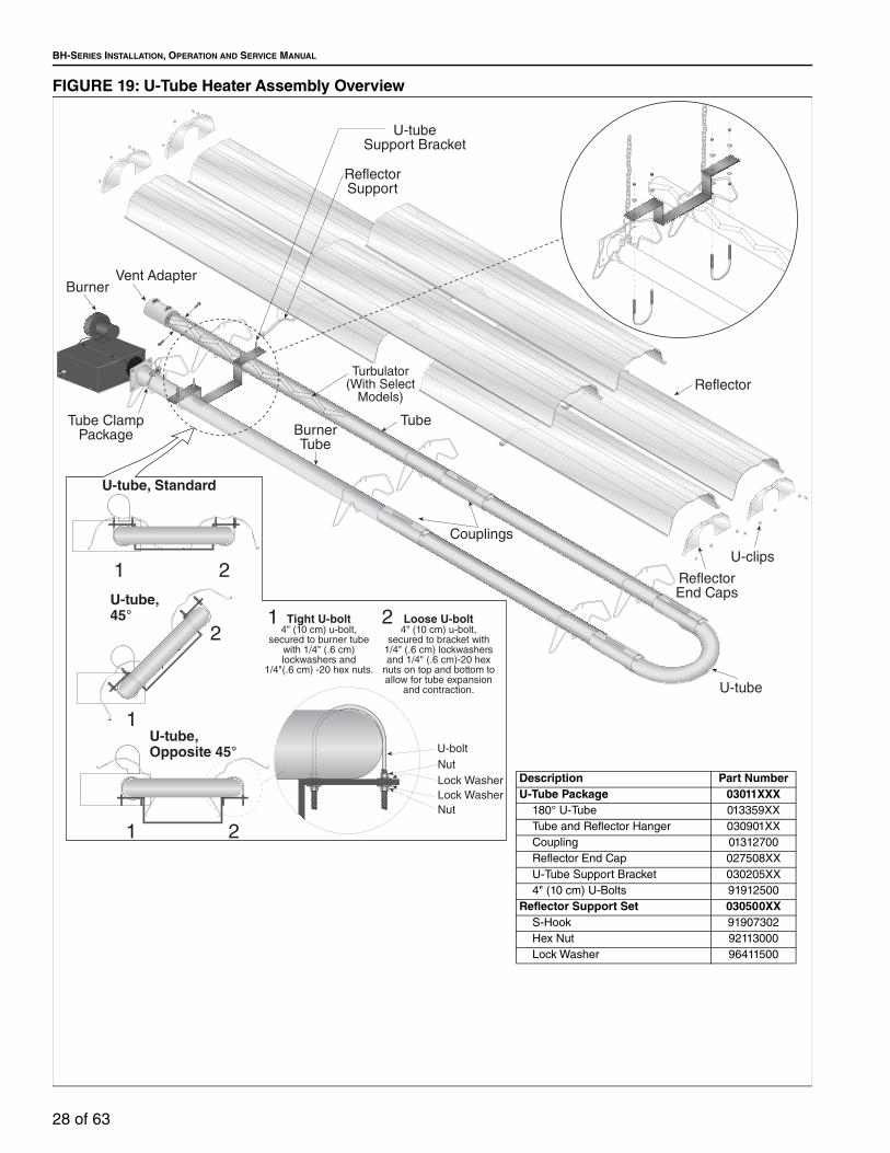
7.1 U-Tube ConfigurationHeaters (except BH-40) are approved for optional U-tube configurations. The U-tube may be installed in either a standard horizontal position, a 45° position or in an opposite 45° position as shown on Page 7, Figure 7 through Page 8, Figure 9. When using a U-tube configuration, the following additional rules must be adhered to:
• A minimum of 10' (3 m) on BH-60/80 and a minimum of 15' (4.5 m) on BH-100/115/125/140/150/175/200 is required between the burner and the U-tube.
• The correct turbulator (See Page 23, Step 6.4) must be installed in the last standard section of the tube.
• The burner must never be operated in a tilted position.
• The heater must be properly supported at all locations. See Page 29, Figure 20.
WARNING
Cut/Pinch Hazard
Wear protective gear during installation, operation and service.
Edges are sharp.
Failure to follow these instructions can result in injury.
BH-SERIES INSTALLATION, OPERATION AND SERVICE MANUAL
28 of 63
FIGURE 19: U-Tube Heater Assembly Overview
Description Part NumberU-Tube Package 03011XXX
180° U-Tube 013359XXTube and Reflector Hanger 030901XXCoupling 01312700Reflector End Cap 027508XXU-Tube Support Bracket 030205XX4" (10 cm) U-Bolts 91912500
Reflector Support Set 030500XXS-Hook 91907302Hex Nut 92113000Lock Washer 96411500

SECTION 7: OPTIONAL HEATER ACCESSORIES
29 of 63
FIGURE 20: U-Tube Heater Layout Overview
������
� � �������� (���������6������8���2����
� � �������� :���,������'�����
� � �������� :���,������+�����
� � !�����"�� <��������7�����+�����
� ���#!��"#�� <��������'�������+������
� ���!���"��� <��������'�������.����7����)���+����������+����)����+�����
� ����"�������� �'������.�����
� ��������$��� �'������+�����
=�(�1����������������� ����������������3�������������������������������������������"
==�(�1�������������������������������3�������������������������������������������"
>3����
'�����
(��������
)�����#!��"#��
)���*(��������+�����
,�������&������-
)�����!���"��� ==
��
� ��
�
�#!����"��� �)����.�����
��
� ��
�
#!��/"��� �)����.�����==
�#!��"��� �)����.�����=
���
�
�
��
� � ��
�
�#!����"��� �)����.�����=�==
%����&�������8���2����

BH-SERIES INSTALLATION, OPERATION AND SERVICE MANUAL
30 of 63
FIGURE 21: U-Tube Layout Overview (Continued)
7.2 Elbow Package ConfigurationStep 7.2.1 Elbow Installation
���
� �
�
� �
���
� �
�
� �
���
� �
�
�
#!���$"�� �)����.�����
#!����"�� �)����.�����==
$#!����"��� �)����.�����
Description Part NumberElbow Package 0271870X
90° Elbow 01335801Coupling 01312700Reflector End Cap 0275080XReflector Joint Piece 0275090X
U-Clip Package 91107720
Minimum Distance Required Between Burner and Elbow
ModelMinimumDistance
BH-40 10' (3 m)BH-60 10' (3 m)BH-80 10' (3 m)BH-100 15' (4.5 m)BH-115 15' (4.5 m)BH-125 15' (4.5 m)BH-140 15' (4.5 m)BH-150 15' (4.5 m)BH-175 15' (4.5 m)BH-200 15' (4.5 m)

SECTION 7: OPTIONAL HEATER ACCESSORIES
31 of 63
Step 7.2.2 Elbow Installation
Step 7.2.3 Reflector Joint Installation
Step 7.2.4 Reflector Joint Installation

BH-SERIES INSTALLATION, OPERATION AND SERVICE MANUAL
32 of 63
Step 7.2.5 Reflector Joint Detail
FIGURE 22: Reflector Joint Detail

SECTION 7: OPTIONAL HEATER ACCESSORIES
33 of 63
7.3 Reflector Side ExtensionStep 7.3.1 Bracket Installation
Step 7.3.2 Side Reflector Installation
(���������2���:;��������'���4���������(��������
>������������������������������������?�����
������������"
)��������(���������+�����
(��������)���
(���������2������
Description Part NumberReflector Side Extension Package 0271270X
Reflector Side Extension 96" (244 cm)
0136800X
Retainer Clips 02751200Sheet Metal Screws 94118106
Order SeparatelyReflector Side Extension Bracket 01329911

BH-SERIES INSTALLATION, OPERATION AND SERVICE MANUAL
34 of 63
7.4 Lower Clearance Shield InstallationStep 7.4.1 Shield Support Strap Assembly
7.5 Two-Foot Decorative Grille InstallationStep 7.5.1 Grille Installation
����#���
(��������
.�����,���������2�����
� ������
�������
���!�
"��#��
&�����@�����+����
Description Part NumberLower Clearance Shield Package 01397501
Shield Support Strap 01397500Lower Clearance Shield 8' (2.4 m) 02793000Locknut #8 92311400Flat Washer #8 95310800Screw #8 x 3/8'' 93511406
Description Part NumberAluminum Grille 2' x 4' (61 x 122 cm) 91407000
SECTION 7: OPTIONAL HEATER ACCESSORIES
35 of 63
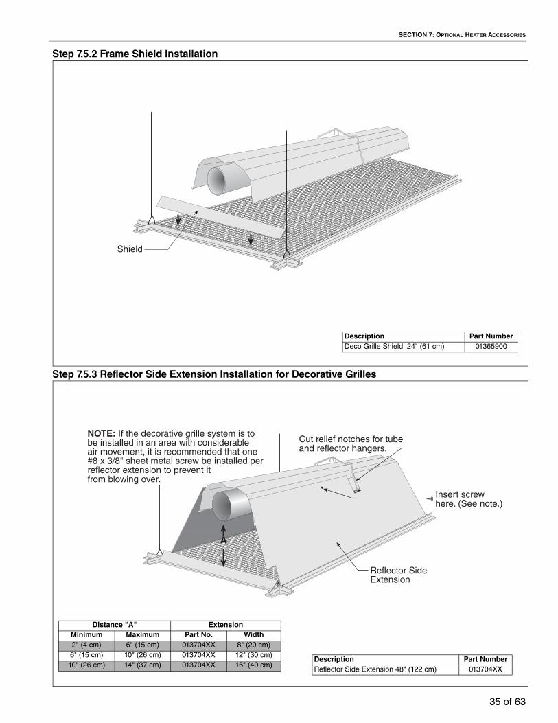
Step 7.5.2 Frame Shield Installation
Step 7.5.3 Reflector Side Extension Installation for Decorative Grilles
Description Part NumberDeco Grille Shield 24" (61 cm) 01365900
Description Part NumberReflector Side Extension 48" (122 cm) 013704XX
Distance "A" ExtensionMinimum Maximum Part No. Width2" (4 cm) 6" (15 cm) 013704XX 8" (20 cm)6" (15 cm) 10" (26 cm) 013704XX 12" (30 cm)10" (26 cm) 14" (37 cm) 013704XX 16" (40 cm)

BH-SERIES INSTALLATION, OPERATION AND SERVICE MANUAL
36 of 63
7.6 Protective Grille InstallationStep 7.6.1 Silicone Cap Installation
Step 7.6.2 Grille End Cap Installation
Step 7.6.3 Grille Installation
2��������,��
9�����7�����
NOTE: Protective Grille NOT APPROVED for use with 45° tilted reflectors.
Description Part NumberGrille Section 08050001Grille End Cap 08050002Grille Section - EF Reflector 08050003Grille End Cap - EF Reflector 08050004Silicone Cap 91915951-6P
����� �$%&'�����!���'
(����� (�������������
A B
C D
� ���� ���������
��������
����� ��������
)�*+,�,��-.

SECTION 8: VENTING
37 of 63
SECTION 8: VENTING
8.1 VentingThis heater must be vented in accordance with the rules contained in this manual and with the following national codes and any state, provincial or local codes which may apply:
United States: Refer to National Fuel Gas Code NFPA 54/ANSI Z223.1 - latest revision.
Canada: Refer to Natural Gas and Propane Installation Code CSA B149.1 - latest revision.
Exhaust end of heater will accept a 4'' (10 cm) vent pipe using the vent adapter (P/N 90502700). To prevent leakage of condensation, install the vent adapter with the seam on top and seal the joint using a high temperature silicone sealant.
Any portion of vent pipe passing through a combustible wall must have an approved thimbleto conform with the above listed codes.
Vent pipe must be sloped downward away from the heater 1/2'' (1 cm) for every 20' (6 m).
The heater may be individually vented or common vented. When venting horizontally, a maximum of two heaters can be commonly vented. See Page 40, Section 8.10. When venting vertically, a maximum of four heaters can be commonly vented. See Page 41, Section 8.11.
The heater may also be installed unvented in certain circumstances according to building ventilation codes. Refer to the above codes and Page 38, Section 8.2 for further information. Unvented operation also requires compliance with the clearances to combustibles given on Page 9, Figure 12.
The bottom of the vent or air intake terminal shall not be located less than 1' (0.3 m) above grade level.
The vent shall not terminate less than 7' (2.1 m) above grade where located adjacent to public walkways.
Vent terminal must be installed at a height sufficient to prevent blockage by snow, and building materials protected from degradation by flue gases.
Secure all joints with #8 x 3/8 sheet metal screws. Seal all joints with high temperature silicone sealant.
Vent terminal must be beyond any combustible overhang.
8.1.1 United States RequirementsVent must terminate at least 3' (0.9 m) above any forced air inlet located within 10' (3.1 m).
Vent must terminate at least 4' (1.2 m) below, 4' (1.2 m) horizontally from, or 1' (0.3 m) above any door, operable window, or gravity air inlet into any building.
8.1.2 Canadian RequirementsThe vent shall not terminate within 6' (1.8 m) of a mechanical air supply inlet to any building.
The vent shall not terminate within 3' (0.9 m) of a window or door that can be opened in any building, any non-mechanical air supply inlet to any building, or of the combustion air inlet of any other appliance.
WARNING
Carbon Monoxide Hazard
Heaters installed unvented must be interlocked with sufficient building exhaust.
Heaters must be installed according to the installation manual.
Failure to follow these instructions can result in death or injury.
WARNING
Cut/Pinch Hazard
Wear protective gear during installation, operation and service.
Edges are sharp.
Failure to follow these instructions can result in injury.

BH-SERIES INSTALLATION, OPERATION AND SERVICE MANUAL
38 of 63
8.2 Unvented OperationSufficient ventilation must be provided in the amount of 4 cfm per 1000 Btu/h firing rate (United States); 3 cfm per 1000 Btu/h firing rate (Canada).
Use of optional outside combustion air is not recommended with unvented heaters.
If exhaust fans are used to supply ventilation air, an interlock switch must be used to prevent the heater from coming on when the fans are off. This may be done using a pressure switch.
8.3 Horizontal VentingIn noncombustible walls only, vent terminal (P/N 02537801-1P) may be used.
For 4" (10 cm) vents in either combustible or noncombustible walls, use Tjernlund VH1-4 (P/N 90502100) or equivalent, insulated vent terminal. Follow the manufacturer's instructions for properinstallation.
For 6" (15 cm) common vents in either combustible or noncombustible walls, use Tjernlund VH1-6 (P/N 90502101) or equivalent, insulated vent terminal. Follow the manufacturer's instructions for proper installation.
8.4 Vertical VentingFor 4'' (10 cm) common vent, an approved vent cap(P/N 90502300) must be used.
For 6'' (15 cm) common vent, an approved vent cap (P/N 90502302) must be used.
For common vertical venting of more than two heaters, See Page 41, Section 8.11.
A vent shall not extend less than 2' (0.6m) above the highest point where it passes through a flat roof of a building.
8.5 Unvented Operation Tube TerminationTurndown type vent terminal with a screen must be installed at the exhaust end of the tube. Vent terminal design shall not incorporate backdraft flap.
FIGURE 23: Tube Termination
8.6 Length RequirementsThe maximum vent length allowed is 45' (13.7 m). The maximum outside air supply duct length allowed is 45' (13.7 m).
The total vent length, plus outside air duct length, plus any extensions to minimum heat exchanger lengths, cannot exceed 65' (19.8 m).
Vent length should be limited to less than 20' (6 m). If using vent lengths greater than 20' (6 m), condensation will form in the vent pipe. Insulation and additional sealing measures (high temperature silicone at all seams) are required. Optional heat exchanger beyond minimum lengths is considered as vent length for length determination.
Subtract 15' (4.6 m) of maximum allowed vent or duct length per vent elbow if more than two are used.
8.7 Vent Material RecommendationsVent recommendations:
1. Porcelain coated tubing 4'' (10 cm) O.D. (P/N 9141030D)
2. Heat treated aluminized tubing 4'' (10 cm) O.D.(P/N 91409408)Heat treated aluminized tubing 6'' (15 cm) O.D.(P/N E0009105)
3. Single wall flue pipe - minimum 26 ga.(Supplied by others)
NOTE: 4" (10 cm) O.D. Porcelain coated tubing (P/N 914030D), 4" (10 cm) O.D. Heat treated aluminized tubing (P/N 91409408), and 6" (15 cm) O.D. Heat treated aluminized tubing (P/N E0009105) are equivalent to single wall flue pipe.
SECTION 8: VENTING
39 of 63
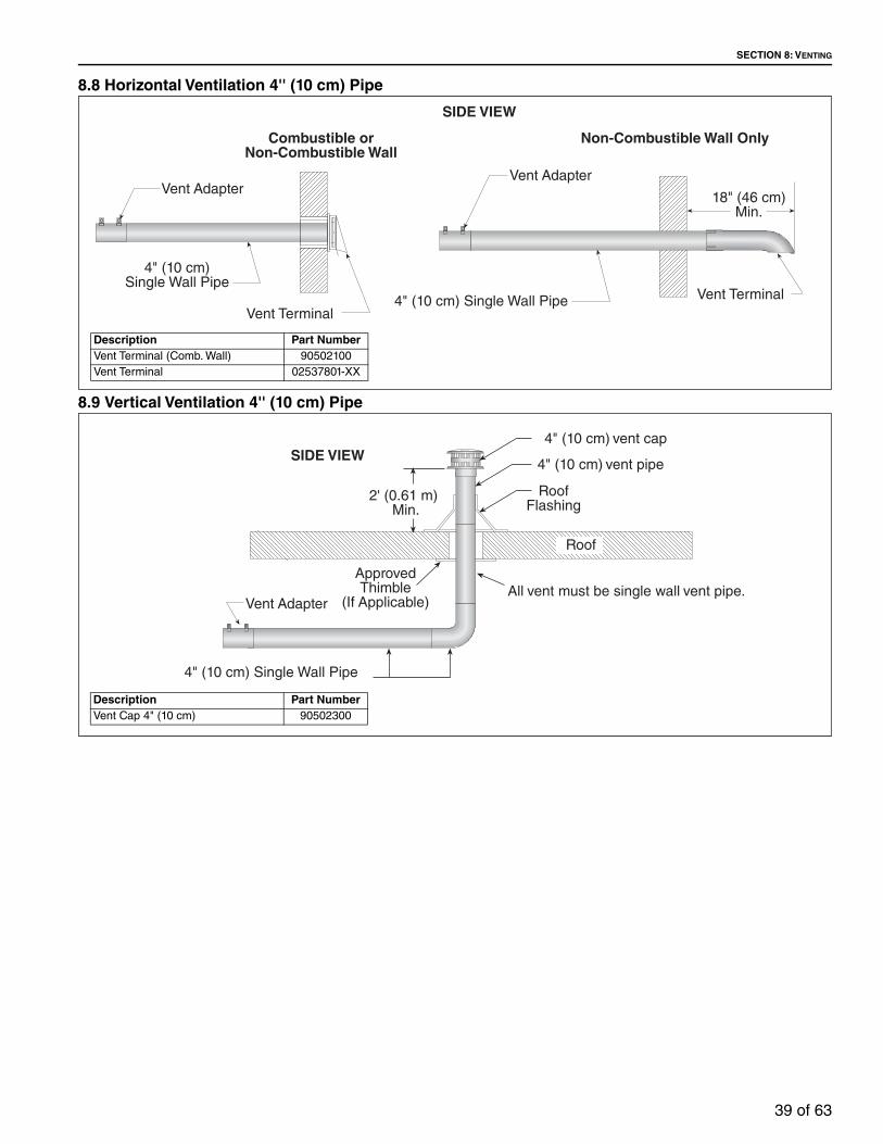
8.8 Horizontal Ventilation 4'' (10 cm) Pipe
8.9 Vertical Ventilation 4'' (10 cm) Pipe
�����#��� 2������6����@���
%����&������
%����)�������
��������� ���������������� ����
%����&������
�$������� A��"
%����)������������#��� �2������6����@���
������������� ���� ��� �
���������
Description Part NumberVent Terminal (Comb. Wall) 90502100Vent Terminal 02537801-XX
Description Part NumberVent Cap 4" (10 cm) 90502300

BH-SERIES INSTALLATION, OPERATION AND SERVICE MANUAL
40 of 63
8.10 Common Side Wall Venting
Requirements:
• Maximum of two heaters can be commonly vented through a side wall.
• Heaters must be of the same BTU output.
• Heaters must be controlled by a common thermostat.
Description Part NumberVent Terminal 6" (15 cm) 90502101

SECTION 8: VENTING
41 of 63
8.11 Common Vertical Venting
Requirements:
• Maximum of four heaters can be commonly vented through the roof.
• Heaters must be of the same BTU output.
• Heaters must be controlled by a common thermostat.
• Connections to a common stack must be positioned to avoid direct opposition between streams of combustion gases.

BH-SERIES INSTALLATION, OPERATION AND SERVICE MANUAL
42 of 63
8.12 Outside Combustion Air SupplyIMPORTANT: If the building has a slight negative pressure or corrosive contaminants, such as halogenated hydrocarbons, are present in the air, an outside combustion air supply to the heater is required. Seal all combustion air pipe joints.
Use of optional outside combustion air is not recommended with unvented heaters.
The air supply duct may have to be insulated to prevent condensation on the outer surface. The outside air terminal must not be more than 1' (31 cm) above the vent termination while maintaining a minimum distance of 3' (93 cm) for both vertical and horizontal venting.
8.12.1 Length RequirementsFollow the constraints listed on Page 38, Section 8.6.
8.12.2 Vertical Outside Air Supply for Single Heater Installation
Description Part NumberVent Cap 4" (10 cm) 90502300

SECTION 8: VENTING
43 of 63
8.12.3 Horizontal Outside Air Supply for Single Heater Installation
8.12.4 Vertical Outside Air Supply for Double Heater Installation
Requirements:
• Heaters must be controlled by a common thermostat.
'����,�����(����������
7��;�+����(����������
%����,�� 6��� �����#���
2������6����@���
'�����
Description Part NumberVent Cap 4" (10 cm) 90502300
Description Part NumberVent Cap 6" (15 cm) 90502302

BH-SERIES INSTALLATION, OPERATION AND SERVICE MANUAL
44 of 63
8.12.5 Horizontal Outside Air Supply for Double Heater Installation
Requirements:
• Heaters must be controlled by a common thermostat.
Description Part NumberVent Cap 6" (15 cm) 90502302

SECTION 9: GAS PIPING
45 of 63
SECTION 9: GAS PIPING Install the gas hose as shown on Page 46, Figure 24. The gas hose accommodates expansion of the heating system and allows for easy installation and service of the burner. Before connecting the burners to the supply system, verify that all high pressure testing of the gas piping has been completed.There is an expansion of the tube with each firing cycle; this will cause the burner to move with respect to the gas hose. This can cause a gas leak resulting in an unsafe condition if the gas connection is not made strictly in accordance with Figure 24 on Page 46.Meter and service must be large enough to handle all the burners being installed plus any other connected load. The gas hose which feeds the system must be large enough to supply the required gas with a maximum pressure drop of 1/2" w.c. When gas piping is not included in the layout drawing, the local gas supplier will usually help in planning the gas piping.
Gas lines must meet applicable codes: United States: The Flexible Stainless Steel Gas Hose (US models) supplied with the heater is certi-fied per the Standard for Connectors for Gas Appli-ances, ANSI Z21.24/CSA 6.10 - latest revision. Canada: The Rubber Type 1 Gas Hose (Canadian models) optional with the heater is certified as being in compliance with the Standard for Elastomeric Composite Hose and Hose Couplings for Conducting Propane and Natural Gas, CAN/CGA 8.1 - Latest revision.
• Check the pipe and tubing ends for leaks before placing heating equipment into service. When checking for gas leaks, use a soap and water solution; never use an open flame.
WARNING
Fire Hazard
Tighten gas hose fittings to connect gas supply according to Figure 23.
Gas hose can crack when twisted.
Gas hose moves during normal operation.
Use only 36" (91 cm) long connector of 1/2" or 3/4" nominal ID.
Connector supplied with heater for U.S. models (not with Canadian models).
Failure to follow these instructions can result in death, injury or property damage.
WARNING
Explosion Hazard
Leak test all components of gas piping before operation.
Gas can leak if piping is not installed properly.
Do not high pressure test gas piping with heater connected.
Failure to follow these instructions can result in death, injury or property damage.

BH-SERIES INSTALLATION, OPERATION AND SERVICE MANUAL
46 of 63
FIGURE 24: Gas Connection with Flexible Gas Hose
Description Part Number1/2" Flexible Stainless Steel Gas Hose (US Models) 914122003/4" Flexible Stainless Steel Gas Hose (US Models) 914122041/2" Rubber Type 1 Gas Hose (Canadian Models) 914122063/4" Rubber Type 1 Gas Hose (Canadian Models) 91412207
Description Part NumberHigh gas pressure regulator ½” – 2 PSI 90207600High gas pressure regulator ¾” – 5 PSI 90207602
See Page 61, Section

SECTION 10: WIRING
47 of 63
SECTION 10: WIRINGHeaters can be controlled using several methods. Normally thermostats are used to control the heaters but they can also be controlled by an energy management system. Section 10.1 illustrates the connection for heaters controlled by a line voltage thermostat.
For heaters on a low voltage thermostat, See Page 48, Section 10.2. Heaters must be grounded in accordance with applicable codes: United States: Refer to National Electrical Code® NFPA 70 - latest revision; Canada: Refer to Canadian Electrical Code CSA C22.1 Part I - latest revision.
If any of the original internal wiring must be replaced, it must be replaced with wiring materials having a temperature rating of at least 105 °C and 600 volts.
10.1 Line Voltage Thermostat Wiring
DANGER
Electrical Shock Hazard
Disconnect electric before service.
Heater must be properly earthed.
Failure to follow these instructions can result in death or electrical shock.

BH-SERIES INSTALLATION, OPERATION AND SERVICE MANUAL
48 of 63
10.2 Low Voltage Thermostat Wiring
Description Part NumberSPST Transformer Relay 90425101Low Voltage Thermostat 90425100

SECTION 10: WIRING
49 of 63
10.3 Internal Wiring
L1L2
L
G
N
YELLOW
YELLOW
YELLOW
GREEN
GREEN
GREEN
BLUEBLACK
BLACK
BLACKWHITE
WHITE
BROWNBLUE
5 4
1 3
3
1
IGNITER
SWITCHPRESSURE
VALVEGAS
TRANSFORMER
MODULEIGNITION
16
19
18
TH S1V1 V2/GND
C1 C2
DS1
FC+
FC-

BH-SERIES INSTALLATION, OPERATION AND SERVICE MANUAL
50 of 63
10.4 Ladder Diagram
10.5 Electrical Connection to the Burner

SECTION 11: OPERATION AND MAINTENANCE
51 of 63
SECTION 11: OPERATION AND MAINTENANCE
This heater is equipped with a direct spark ignition system.
11.1 Sequence of Operation4. Turn the thermostat up. When the thermostat
calls for heat, the blower motor will energize.
5. When the motor approaches nominal running RPM, the pressure switch closes and activates the ignition module.
6. After a 45 second prepurge, the ignition module then opens the gas valve and energizes the spark igniter.
7. When the flame is established, the sparking sequence ceases.
8. If the flame is not established during the ignition sequence, the ignition module closes the gas valve and purge begins. Module will try 2 additional times for ignition (with purges in between trials). If ignition is not established, the module will lockout.
9. If the flame extinguishes during operation, the ignition module will attempt the multiple trial sequence described in step 5. If ignition is not re-established, the module will lockout for one hour or until reset.
10.After lockout, the control can be reset by turning down thermostat for five seconds, and then raising it again to desired temperature, or by disconnecting power and then reconnecting.
11. When thermostat is satisfied, all power to the unit is shut off.
11.2 To Shut Off HeaterSet thermostat to lowest setting.Turn OFF electric power to heater.Turn OFF manual gas valve in the heater supply line.
11.3 To Start HeaterTurn gas valve and electric power OFF and wait five minutes for unburned gases to vent from heater.Turn ON main gas valve.Turn ON electric power.Set thermostat to desired temperature. Burner should light automatically.
11.4 Pre-Season Maintenance and Annual InspectionTo ensure your safety and years of trouble-free operation of the heating system, service and annual inspections must be done by a contractor qualified in the installation and service of gas-fired heating equipment.Turn off gas and electric supplies before performing service or maintenance. Allow heater to cool before servicing.Before every heating season, a contractor qualified in the installation and service of gas-fired heating equipment must perform a thorough safety inspection of the heater.For best performance, the gas, electrical, thermostat connections, tubing, venting, suspensions and
Cut/Pinch Hazard
Wear protective gear during installation, operation and service.
Edges are sharp.
WARNING
Failure to follow these instructions can result in death, electric shock, injury or property damage.
Burn Hazard
Allow heater to cool before service.
Tubing may still be hot after operation.
Explosion Hazard
Turn off gas supply to heater before service.
DANGER
Electrical Shock Hazard
Disconnect electric before service. Heater must be connected to a properly grounded electrical source.
BH-SERIES INSTALLATION, OPERATION AND SERVICE MANUAL
52 of 63
overall heater condition should be thoroughly inspected.NOTE: Gas flow and burner ignition are among the first things that should be throughly inspected.Please see Page 52, Section 11.5 for suggested items to inspect.
11.5 Maintenance Checklist
Installation Code and Annual Inspections: All installation and service of ROBERTS GORDON® equipment must be performed by a contractor qualified in the installation and service of equipment sold and supplied by Roberts-Gordon LLC and
conform to all requirements set forth in the ROBERTS GORDON® manuals and all applicable governmental authorities pertaining to the installation, service, operation and labeling of the equipment.
To help facilitate optimum performance and safety, Roberts-Gordon LLC recommends that a qualified contractor conduct, at a minimum, annual inspections of your ROBERTS GORDON® equipment and perform service where necessary, using only replacement parts sold and supplied by Roberts-Gordon LLC.
The Vicinity of the Heater Do not store or use flammable objects, liquids or vapors near the heater. Immediately remove these items if they are present.
See Page 5, Section 3.Vehicles and Other Objects
Maintain the clearances to combustibles.
Do not hang anything from, or place anything on, the heater.
Make sure nothing is lodged underneath the reflector, in between the tubes or in the decorative or protective grilles (included with select models).
Immediately remove objects in violation of the clearances to combustibles.
See Page 5, Section 3.Reflector Support reflector with reflector hanger and support strap.
Reflector must not touch tube.
Make sure there is no dirt, sagging, cracking or distortion.
Do not operate if there is sagging, cracking or distortion.
Make sure reflectors are correctly overlapped. See Page 25, Section 6.5.1.
Clean outside surface with a damp cloth.Vent Pipe Venting must be intact. Using a flashlight, look for obstructions, cracks on the
pipe, gaps in the sealed areas or corrosion.
The area must be free of dirt and dust.
Remove any carbon deposits or scale using a wire brush.
See Page 37, Section 8.Outside Air Inlet Inlet must be intact. Look for obstructions, cracks on the pipe, gaps in the
sealed areas or corrosion.
The area must be free of dirt and dust. Clean and reinstall as required.Tubes Make sure there are no cracks.
Make sure tubes are connected and suspended securely.
See Page 16, Section 6.
Make sure there is no sagging, bending or distortion.Clean or replace as required.
Gas Line Check for gas leaks. See Page 45, Section 9.Burner Observation Window
Make sure it is clean and free of cracks or holes.
Clean and replace as required.

SECTION 11: OPERATION AND MAINTENANCE
53 of 63
Blower Scroll, Wheel and Motor
Compressed air or a vacuum cleaner may be used to clean dust and dirt.
Burner Cup and Orifice Clear of obstructions (even spider webs will cause problems).
Carefully remove any dust and debris from the burner.Electrode Replace if there are cracked ceramics, excessive carbon residue, or erosion
of the electrode.
The electrode gap should be 1/8" (3.2 mm).Thermostat There should be no exposed wire or damage to the thermostat.
See Page 47, Section 10.Suspension Points Make sure the heater is hanging securely. Look for signs of wear on the chain
or ceiling.
See Page 17, Figure 15.Decorative and Protective Grille (optional)
The grille must be securely attached.
Check that the side reflector extensions are installed correctly and secured in place if necessary. (Decorative grille only.)
See Page 34, Section 7.5 and Page 36, Section 7.6
Make sure shield is installed correctly and secured in place if necessary. (Decorative grille only.) See Page 35, Section 7.5.2.
Lower Clearance Shield (optional)
The lower shield must be securely attached. Inspect shield support straps and lower clearance shield anchor points.
See Page 34, Section 7.4.
Make sure shield is installed correctly and secured in place if necessary.
See Page 34, Section 7.4.Wall Tag If wall tag is present, make sure it is legible and accurate. Please contact
Roberts-Gordon LLC or your ROBERTS GORDON® independent distributor, if you need a wall tag. See Page 4, Section 2.1
Safety Labels Product safety signs or labels should be replaced by the product user when they are no longer legible. Please contact Roberts-Gordon LLC or your ROBERTS GORDON® independent distributor to obtain replacement signs or labels. See Page 2, Figure 1 through Page 3, Figure 2.

BH-SERIES INSTALLATION, OPERATION AND SERVICE MANUAL
54 of 63
SECTION 12: TROUBLESHOOTING
DANGER
Electrical Shock Hazard
Disconnect electric before service.
Heater must be properly earthed.
Failure to follow these instructions can result in death or electrical shock.
Fire Hazard
Keep all flammable objects, liquids and vapors the minimum required clearances to combustibles away from heater.
Some objects will catch fire or explode when placed close to heater.
Cut/Pinch Hazard
Wear protective gear during installation, operation and service.
Edges are sharp.
WARNING
Failure to follow these instructions can result in death, injury or property damage.
Burn Hazard
Allow heater to cool before service.
Tubing may still be hot after operation.
Explosion Hazard
Turn off gas supply to heater before service.

SECTION 12: TROUBLESHOOTING
55 of 63
12.1 Troubleshooting Flow Chart
Mo
du
le D
iag
no
sti
c C
od
es
:L
ED
P
rob
lem
S
olu
tio
n4
se
con
d s
tea
dy
flash
at
sta
rt o
f cy
cle
N
orm
al
Wa
it fo
r va
lve
to
op
en
Ste
ad
y o
n
Mic
rop
roce
sso
r fa
ilure
R
ep
lace
mo
du
le
w
ithin
mo
du
le
Th
ree
fla
she
s Ig
niti
on
lock
ou
t R
ecy
cle
un
it: c
he
ck fo
r
Lock
ou
t o
f m
odu
le
spa
rk a
nd
va
lve
op
en
ing
an
d
a
fter
3 t
rie
s re
pla
ce:if
no
ne,
rep
lace
mo
du
le

BH-SERIES INSTALLATION, OPERATION AND SERVICE MANUAL
56 of 63

SECTION 12: TROUBLESHOOTING
57 of 63
12.2 Manifold Gas Pressure Setting
Top View of Heater
Manometer
Natural Propane
65432101
65432
3.5” 10.5”
65432101
65432

BH-SERIES INSTALLATION, OPERATION AND SERVICE MANUAL
58 of 63
SECTION 13: REPLACEMENT PARTS
See warnings and important information before removing or replacing parts. After any maintenance or repair work, always test fire the heater in accordance with the start-up instructions on Page 51, Section 11 to help ensure all safety systems are in working order before leaving the heater to operate. Minor faults may be traced by using the troubleshooting charts on Page 54, Section 12 through Page 57, Figure 12.2.
Carbon Monoxide Hazard
WARNING
Use only genuine ROBERTS GORDON® replacement parts per this installation, operation and service manual.
Failure to follow these instructions can result in death, electric shock, injury or property damage.
Explosion Hazard
DANGER
Electrical Shock Hazard Fire Hazard

SECTION 13: REPLACEMENT PARTS
59 of 63
Blower Assembly
DSI Ignition Module
Blower Outlet Gasket
REAR VIEW
TOP VIEWTube Gasket
ElectrodeMica Window Assembly
Burner Cup Assembly
Gas Valve
Pressure Switch
Transformer

Description Part NumberMica Window Assembly 02553203Electrode Gasket 02558501Tube Gasket 02568200Burner Cup Assembly 03020100Gas Valve (Natural) 90032510Gas Valve (LP) 90032512Electrode 90427400DSI Ignition Module 90439500KTransformer 90436900KPressure Switch
(200) 90439801K(115, 140, 175) 90439802K(150) 90439803K(60, 80, 100, 125) 90439805K(40) 90439808K
Motor/Blower Assembly 90709700-PBlower Outlet Gasket 90709801

SECTION 14: GENERAL SPECIFICATIONS
61 of 63
SECTION 14: GENERAL SPECIFICATIONS14.1 Material Specifications14.1.1 Reflectors.024 Aluminum(Optional .024 Stainless Steel Type 304)
14.2 Heater Specifications14.2.1 IgnitionFully automatic, three-try, direct spark, electronic ignition control, 100% safety shut-off.
14.3 Suspension SpecificationsHang heater with materials with a minimum working load of 75 lbs (33 kg). See Page 17, Figure 15.
14.4 Controls SpecificationsTime switches, thermostats, etc. can be wired into the electrical supply. External controls supplied as an optional extra.
General Specifications for BH-Series heaters are as follows:
*See Page 5, Section 3 for clearances to combustibles.
GAS PRESSURE AT MANIFOLD:Natural Gas: 3.5" wcLP Gas: 10.5" wcPIPE CONNECTION:1/2" NPT (for BH-40, 60, 80, 100, 115 & 125)3/4" NPT (for BH- 140, 150,175 & 200)DIMENSIONS:Vent Connection Size: 4" (10 cm)Outside Air Connection Size: 4" (10 cm)Refer to figure above for dimensional information.
GAS INLET PRESSURE:Natural Gas: for BH-40, 60, 80, 100, 115, 125, 140, 150 4.6" wc Minimumfor BH-175, 200 5.0" wc Minimum
14.0" wc MaximumLP Gas: 11.0" wc Minimum
14.0" wc MaximumELECTRICAL RATING (ALL MODELS):120 V - 60 Hz, 1 A (run)
����������������������
������ ��������
�/'0��1/����
������
����/2����
�����������3�������"����� ���������
�/'0��1/����
Heat Input Rate Length “A”Recommended
Minimum Mounting Height*
Model (Btu/h) x (1000) Minimum Space Spot
BH-40 40 10' (3 m) 8-10' (2.4 - 3 m) 8'(2.4 m)
BH-60 60 20' (6 m) 10-12' (3 - 3.6 m) 9' (2.7 m)
BH-80 80 20' (6 m) 12-15' (3.6 - 4.5 m) 11' (3.3 m)
BH-100 100 30' (9 m) 12-15' (3.6 - 4.5 m) 12' (3.7 m)
BH-115 115 30' (9 m) 15-20' (4.5 - 6 m) 15' (4.6 m)
BH-125 125 40' (12 m) 15-20' (4.5 - 6 m) 15' (4.6 m)
BH-140 140 40' (12 m) 20-25' (6 - 7.6 m) 20' (6.1 m)
BH-150 150 50' (15 m) 20-25' (6 - 7.6 m) 20' (6.1 m)
BH-175 175 50' (15 m) 25' (7.6 m) 23' (7 m)
BH-200 200 60' (18 m) 25' (7.6 m) 25' (7.6 m)

BH-SERIES INSTALLATION, OPERATION AND SERVICE MANUAL
62 of 63

SECTION 15: THE ROBERTS GORDON® GORDONRAY™ BH WARRANTY
63 of 63
SECTION 15: THE ROBERTS GORDON® GORDONRAY™ BH WARRANTYROBERTS-GORDON LLC WILL PAY FOR:Within 36 months from date of purchase by buyer or 42 months from date of shipment by Roberts-Gordon LLC (whichever occurs first), replacement parts will be provided free of charge for any part of the product which fails due to a manufacturing or material defect. Roberts-Gordon LLC will require the part in question to be returned to the factory. Roberts-Gordon LLC will, at its sole discretion, repair or replace after determining the nature of the defect and disposition of part in question. ROBERTS GORDON® Replacement Parts are warranted for a period of 12 months from date of shipment from Roberts-Gordon LLC or the remaining ROBERTS GORDON® GORDONRAY™ BH warranty.ROBERTS-GORDON LLC WILL NOT PAY FOR:Service trips, service calls and labor charges.Shipment of replacement parts.Claims where the total price of the goods have not been paid.Damage due to:
• Improper installation, operation or maintenance.• Misuse, abuse, neglect, or modification of the
ROBERTS GORDON® GORDONRAY™ BH in any way.
• Use of the ROBERTS GORDON® GORDONRAY™ BH for other than its intended purpose.
• Incorrect gas or electrical supply, accident, fire, floods, acts of God, war, terrorism, or other casualty.
• Improper service, use of replacement parts or accessories not specified by Roberts-Gordon.
• Failure to install or maintain the ROBERTS GORDON® GORDONRAY™ BH as directed in the Installation, Operation and Service Manual.
• Relocation of the ROBERTS GORDON® GORDONRAY™ BH after initial installation
• Use of the ROBERTS GORDON® GORDONRAY™ BH in a corrosive atmosphere containing contaminants.
• Use of the ROBERTS GORDON® GORDONRAY™ BH in the vicinity of a combustible or explosive material.
• Any defect in the ROBERTS GORDON® GORDONRAY™ BH arising from a drawing, design, or specification supplied by or on behalf of the consumer.
• Damage incurred during shipment. Claim must be filed with carrier.
WARRANTY IS VOID IF:The ROBERTS GORDON® GORDONRAY™ BH is not installed by an contractor qualified in the installation and service of gas fired heating equipment.You cannot prove original purchase date and required annual maintenance history.
The data plate and/or serial number are removed, defaced, modified or altered in any way.The ownership of the ROBERTS GORDON® GORDONRAY™ BH is moved or transferred. This warranty is non-transferable.Roberts-Gordon LLC is not permitted to inspect the damaged equipment and/or component parts.READ YOUR INSTALLATION, OPERATION AND SERVICE MANUAL.If you have questions about your equipment, contact your installing professional. Should you need Replacement Parts or have additional questions, call or write:
Roberts-Gordon LLC1250 William StreetP.O. Box 44Buffalo, New York 14240-0044Telephone: +1.716.852.4400Fax: +1.716.852.0854Toll Free: 800.828.7450www.robertsgordon.com
Roberts-Gordon LLC's liability, and your exclusive remedy, under this warranty or any implied warranty (including the implied warranties of merchantability and fitness for a particular purpose) is limited to providing replacement parts during the term of this warranty. Some jurisdictions do not allow limitations on how long an implied warranty lasts, so this limitation may not apply to you. There are no rights, warranties or conditions, expressed or implied, statutory or otherwise, other than those contained in this warranty.
Roberts-Gordon LLC shall in no event be responsible for incidental or consequential damages or incur liability for damages in excess of the amount paid by you for the ROBERTS GORDON® GORDONRAY™ BH. Some jurisdictions do not allow the exclusion or limitation of incidental or consequential damages, so this limitation or exclusion may not apply to you. This warranty gives you specific legal rights, and you may also have other rights which vary from jurisdiction to jurisdiction.
Roberts-Gordon LLC shall not be responsible for failure to perform under the terms of this warranty if caused by circumstances out of its control, including but not limited to war, fire, flood, strike, government or court orders, acts of God, terrorism, unavailability of supplies, parts or power. No person is authorized to assume for Roberts-Gordon LLC any other warranty, obligation or liability.
LIMITATIONS ON AUTHORITY OF REPRESENTATIVES:No representative of Roberts-Gordon LLC, other than an Executive Officer, has authority to change or extend these provisions. Changes or extensions shall be binding only if confirmed in writing by Roberts-Gordon LLC's duly authorized Executive Officer.

2017

SECTION 15: THE ROBERTS GORDON® GORDONRAY™ BH WARRANTY
69 of 63


