1. Oilchange 2. Maintenanceandcare 3. Sprocketreversing ... · 5. Changing the gear mech The...
26
86 1. Oil change 2. Maintenance and care 3. Sprocket reversing/replacing 4. Changing of brake discs 5. Changing the gear mech ................................................................................................................ 87 89 ............................................................................. 90 ...................................................................................... 91 5.1 Removal of one-piece axle ring ........................................................................... 92 5.2 Removal of quick-change axle ring ..................................................................... 92 5.3 Mounting the external gear mech ......................................................................... 93 ..........................................................................................
Transcript of 1. Oilchange 2. Maintenanceandcare 3. Sprocketreversing ... · 5. Changing the gear mech The...

86
1. Oil change
2. Maintenance and care
3. Sprocket reversing/replacing
4. Changing of brake discs
5. Changing the gear mech
................................................................................................................ 87
89
............................................................................. 90
...................................................................................... 91
5.1 Removal of one-piece axle ring ........................................................................... 92
5.2 Removal of quick-change axle ring ..................................................................... 92
5.3 Mounting the external gear mech ......................................................................... 93
..........................................................................................

87
21
AB
C
D
E
1. Oil change
An oil change should be annually carried out or at least every 5000km. Through this process it can be safe to say that
there will always be enough oil in the hub regardless of oil loss (due to sweat oil) and that any penetrated water will be
rinsed out.
For a problem-free oil change we recommend the use of the Oil Change Kit (Art.N° 8410).Rohloff
The Oil Change Kit consists of:
25ml cleaning oil in a 50ml
bottle*
25ml
Oil filling tube
Non returnable syringe 50ml
Drain screw with new seal
The oil filling tube should be pla-
ced over the syringe and secured
with a drop of super-glue before
use.
A
B
C
D
E
Rohloff SPEEDHUB OIL * There will already be approx.
25ml fluid in the hub (old oil and
any penetrated moisture). After the
cleaning oil is also filled into the
hub then there will be approx.
50ml fluid to drain out. For this
reason the cleaning oil comes in a
50ml bottle so that the old fluid
can be drained out into this bottle
for safe disposal.
P OI NTE R
To rinse the hub properly, ride
approx. 1km or turn the wheel by
hand using the cranks for approx.
3min whilst simultaniously
swiching between gears #3 and #5.
In these gears all planetary gear
sets are in use, making sure that
the cleaning fluid is well rinsed
through in order to thin out the old
oil for easier removal.
To change the oil, the
should be left
at room temperature (because the
oil flows better). Turn the hub, so
that the drain screw can be seen on
the top. Remove drain screw (3mm
allen key).
Rohloff
SPEEDHUB 500/14
Draw the 25ml cleaning oil into
the syringe, screw the filling tube
into the drain screw hole and fill
the cleaning oil into the hub. After
this, use the syringe to draw out a
little air out into the syringe.
Remove the filling tube and refit
the drain screw.
Service
T I PIt is important to protect the brake
disk/ pads (if mounted) with a
clean cloth to minimize the
possiblity that oil could spray out
onto them.
88
543
Fit the new drain screw using a
drop of loctite (eg Loctite 511) and
screw in tight (3mm allen key,
tightening torque 0.5Nm/4in.lbs.).
Draw 25ml into
the syringe and insert this into the
hub. Draw out approx. 25ml of air
to keep the pressure correct inside
and therefore, avoid oil seeping
back out, when removing the
filling tube.
SPEEDHUB OIL
ATTE NT I ONThe
must be filled
oils
. The use of other types of
lubricants and/or cleaning fluids
could lead to the damage of the
inner mechanism's nylon
components.
Used oil should be taken to a
specialized oil disposal point, so as
to keep pollution levels down.
and
cleaning oil can be disposed of
together with other motor oils.
Rohloff SPEEDHUB 500/14
Rohloff SPEEDHUB OIL
exclusively with
(gear box/cleaning
oils)
Rohloff
Remove the drain screw (3mm
allen key) and refit the filling tube
and syringe. Turn the wheel, so
that the filling point is underneath
the hub. Wait approx. 15mins with
the wheel in this position, then use
the syringe to draw out the old
fluid. Remove the syringe and
filling tube, use this to pour the
fluid into the 50ml cleaning oil
bottle.
Service

89
543
21
On the versions with an internal
gear mech the cable adjusters can
be found on the cable guide. This
can be found on the left hand chain
stay or attached to the left hand
brake boss of the frame.
On the versions with an external
gear mech the cable adjusters can
be found on the cable box. This
sits directly on the left hand side of
the
These cables are either routed
along the seatstay or the chainstay
of the frame.
Rohloff SPEEDHUB 500/14.
To lubricate the chain tensioner,
place a drop of oil on the left and
right side of the upper jockey
wheel on the pivot point.
Rohloff SPEEDHUB 500/14 ver-
sions with external gear mech: To
lubricate the cable pulley bearing,
remove the cable box and place a
little grease on the parts arrowed in
the picture above.
When lubricating the chain, place a
thin thread of lubricant on the out-
side of the chain over the centre rol-
lers. This process is carried out qui-
cker and easier, when running the
chain backwards whilst applying
the lubricant.
2. Maintenance and care
The shifter cable tension can be
altered by the cable adjusters. When
winding the cable adjusters out, the
cable tension is increased. For the
lightest possible gear change, the
tension should be just enough, so
that on the twist shifter there is
approx. 1/2 gear (2mm) rotational
play, when in a selected gear. The
dot on the twist shifter body can be
aligned to the correct gear number
without altering the cable tension,
by winding one cable adjuster in
and the other out.
Too much cable tension raises the
amount of friction within the shifter
cables and in turn, raises the force
needed on the twist shifter to select
other gears.
Service
ATTE NT I ON
ATTE NT I ONWhen using a disc brake in conjunction with the , the hub cap screws should bechecked that they are correctly tightened before every ride.To reduce the chance of a flange breaking due to unequal spoke tension, we recommend that this is regularlychecked by a professional bicycle mechanic.
Rohloff SPEEDHUB 500/14
90
321
2a
3. Sprocket reversing/replacing
The sprocket sizes 15, 16 and 17 of the are symmetrical and are therefore reversable,
when worn on one side. After reversing the sprocket, fit a new chain. This will now pull on the other, unworn side of
the sprocket. Once both sides are worn, the sprocket must be replaced. The 13 tooth sprocket is not reversable, and the-
refore, must always be replaced once worn.
Rohloff SPEEDHUB 500/14
Check that the seats on the driver
are clean so that the tool can be
properly seated. Place the sprocket
tool over the clean seats of the
driver and with a quick release
lever (CC) or an axle nut (TS)
secure in position, so that the
sprocket tool is prevented from
springing out of the seats.
Hold the sprocket tool steady with
a 24mm wrench and using a chain
whip turn the sprocket
anticlockwise in the opposite
direction to the 24mm wrench.
The sprocket can be removed over
the sprocket tool. When only
reversing the sprocket, clean the
sprocket turn it over 180° and
screw it back onto the cleaned and
regreased thread of the driver in a
clockwise direction. Tighten up the
sprocket using the chain whip. If
the sprocket needs to be replaced,
simply screw the new sprocket
tightly onto the driver.
Make sure that the spr
hen mounting or dismounting the
sprocket, always T
hen
attempting this removal/assembly
procedure with an unsecured
sprocket tool.
ocket
remover tool is properly secured
w
he driver could
get severly damaged, w
P OI NTE RPlacing the new/reversed sprocket
onto the driver over the sprocket
tool helps the sprocket to sit evenly
on the thread, so as to eliminate the
possibility of cross-threading.ATTE NT I ON
Service
Check the sprocket for signs of da-
mage or wear caused by the hub se-
al.If needed, reverse or replace it
for a sprocket with undamaged seal
surfaces immediately. This will in
turn reduce the possibility that oil
could seep out.
Possible ring of wear or damageon the seal surface.
ATTE NT I ON
P OI NTE RMake sure that the area around the
sprocket and hubshell is free from
dirt, so that this cannot penetrate in-
to the gear-unit during this process.

91
6
M
54
3
M
2L1
The external transfer box must
not be removed as the cogs
within the box could fall out of
synchroni-zation. See chapter
"Service" paragraph 5.
"Changing the gear mech".
4. Changing of brake discs
If the brake disc is worn or needs to be replaced by a different brake type, the rear wheel along with the axle plate will
have to be removed before the replacement of the disc can be carried out.
Mark the axle plate, so that it can
be replaced later in the same
position. Remove the axle plate
screws .
Remove the axle plate and secure
the external transfer box to the hub
with one of these screws L.
(M4 25 - Torx TX20)x
Place the new brake disc over
the external transfer box and
down onto the center disc mount
(pay attention to the rotational
direction of the brake disc).
Replace the four mounting bolts
(M8 0.75 8.5 - 5mm allen key,
tightening torque 7Nm/61in.lbs.).
Remove the axle plate screw
from the external transfer box.
Remount the axle plate in the
correct position and secure this in
place with the five axle plate
screws
.
M
L
x x
(M4 25 - Torx TX20,
tightening torque: 3Nm/25in.lbs.)
x
Remove the four mounting bolts
(M8 0.75 8.5 - 5mm allen key).
M
x x
Pull the old brake disc off the
center disc mount and remove this
over the external transfer box.
The removal of the axle plate is
not necessary on the OEM
versions, where the axle plate is
secured to the hub in the position
shown in the above diagram. The
brake disc can simply be removed
over the external transfer box and
the axle plate together.
Service
ATTE NT I ON
new
old
92
321
321
5. Changing the gear mech
The replacement of the gear mech is normally only needed, when mounting the hub on a different bicycle frame.
It is not routine work and we advise that this work is carried out by a professional bicycle workshop.
5.1 Removal of one-piece axle ring
Regardless of which axle plate is
mounted, the axle plate must be
removed by unscrewing all six of
the axle plate screws (M4 25 -
Torx TX20).
x
Lie the wheel on a flat surface with
the axle ring facing up and the ca-
ble guides facing to the right. Rock
the axle ring from side to side
whilst pulling it upwards in order
to loosen it from the hub.
Should the axle ring not loosen by
hand, use a pipe wrench to hold the
axle ring tight (place cardboard bet-
ween the axle ring and the pipe
wrench). Rock the axle ring from
side to side with the pipe wrench,
whilst pulling it upwards in order
to loosen it from the hub.
5.2 Removal of quick-change axle ring
Regardless of which axle plate is
mounted, the axle plate must be
removed by unscrewing all five of
the axle plate screws (M4 25 -
Torx TX20).
x
Lie the wheel on a flat surface with
the axle ring facing up and the ca-
ble guides facing to the right. Pull
the cable guides with the nylon cy-
linders and the cable pulley up-
wards and out of the axle ring.
Remove the axle ring screw
(M4 20 - Torx TX20) and rock the
axle ring from side to side, whilst
pulling it upwards in order to loo-
sen it from the hub.
x
T I P
Service

93
654
321
Shift the gearbox into gear #14 by
turning the hexagonal peg with an
8mm wrench carefully in a
clockwise direction to the end stop.
5.3 Mounting the external gear mech
Hold the aluminium nut on the
sprocket side with a 17mm wrench
to prevent the axle from moving,
whilst selecting the gear.
Place a new paper gasket over the locating pegs of the external transfer
box, so that all holes meet up with corresponding screw holes of the axle
ring. The smaller seal sits in the recess on the rear side of the axle ring.
Mount the external transfer boxonto the gearbox.
Service
ATTE NT I ONThe wheel must not be laid on the
axle ring side once the axle ring
has been removed because:
a. Oil could leak out of the holes.
b. The two freewheel springs could
fall out of the locating peg
holes.
The grub screw under the ExternalGear Mech should be fitted in thecorrect position.
.
“Appendix -Grub screw of the External GearMech”
P OI NTE R
94
9
D F
8 D E
10
D
7
C
F
D
E
11
Place the cable pulley over the
hexagonal peg of the external
transfer box and then rotate it until
the two screw holes sit on the
center line , as shown in the
diagram above. Hold the cable
pulley in this position.
F
Insert cog over the hexagonalpeg with the toothing facingoutward. There is one mountingposition out of the possible six,where the teeth of the cog andthe sprocket line up. In thisposition the screw holes of thecable pulley remain as close aspossible along the center line
.
DE
DC
F This position is the correctposition. It may be neccessary toturn the cable pulley lightly to theleft or right to allow for an easierassembly.
The five other mounting positions
result in the screw holes of the
cable pulley being substantially
more out of line with the center
line . In this case, remove the cog
and try the next mounting
position.
F
D
Place a small amount of grease
between the cog D and the external
transfer box. Remount the axle
plate and secure it in the correct
position with the five axle plate
screws (M4 25 - Torx TX20,
tightening torque 3Nm/25in.lbs.).
x
Grease
Further steps for mounting the
external gear mech can be found in
chapter "Mounting", paragraph 7.3
"External gear mech".
Service
correct
incorrect
ATTE NT I ONThe smaller side of cog must
always be mounted into the
external transfer box facing
inwards. When cog is wrongly
mounted, the axle plate will cause
functional difficulties within the
external transfer box.
D
D

95
A selection of sprockets and the sprocket tool
96
Repairs
1. Changing the hub cable
2. Changing the chain tensioner spring
3. Changing the grip rubber
4. Exchanging the gear unit
5. Hub Seal replacement
6.Appendix
(0.9mm Rohloff special gear cable)............................................ 97
1.1 One-piece axle ring .............................................................................................. 98
1.2 Quick-change axle ring ...................................................................................... 104
............................................................ 108
.................................................................................. 109
4.1 Gear unit removal .............................................................................................. 110
4.2 Gear unit installation .......................................................................................... 111
Failure Diagnosis ........................................................................................................ 119
Trouble Shooting ........................................................................................................ 120
Tools and Bolts ........................................................................................................... 124
Wheel lacing with a European spoke-hole pattern ....................................................... 125
Wheel lacing with a French spoke-hole pattern ........................................................... 126
Technical Data ............................................................................................................ 127
Reference to Serial-N° ................................................................................................ 128
Threaded Pin of the External Gear Mech ..................................................................... 129
Notices ....................................................................................................................... 130

97
5x6x21
1. Changing the hub cable
The method of replacement for a worn or broken hub cable can be carried out differently depending on which axle
ring type is mounted.
1. Axle ring with pressed-in cable guides (one-piece axle ring)
2. Axle ring with cable guides seated within nylon cylinders (quick-change axle ring)
(0.9mm Rohloff special gear cable)
The quick-change axle ring is secu-
red to the gear box with five axle
plate screws. The axle ring remains
secured to the gearbox with one
more screw and the cable guides
seated within black nylon cylinders
rest in the axle ring. This can be
seen once the axle plate has been
removed. When replacing the hub
cable, the axle ring remains atta-
ched to the gearbox.
Replacement procedure
see paragraph 1.2.
The one-piece axle ring was moun-
ted on all internal gear mech ver-
sions until the beginning of 2003.
This type of axle ring is secured to
the gearbox with six axle plate
screws. The cable guides of the
one-piece axle ring remain fixed to
the axle ring. This can be seen on-
ce the axle plate has been remo-
ved. To replace the hub cable, the
axle ring complete with the cable
pulley must be removed.
When correctly mounted, the hub cable should last a good 10,000km. Should the cable get damaged and need to be
replaced sooner, the reason for this damage should be identified and corrected before mounting a new hub cable.
Possible reasons:
1. False alignment of the axle plate or the cable guide can result in the cable rubbing against the metal of the cable
adjusters/guides. (see chapter “Mounting”, paragraph 4.1.2).
2. Torque not properly secured. The hub axle rotated and streched the cables to breaking point.
3. Other physical damage (eg crashes, accidents).
P OI NTE R
Repairs
Replacement procedure
see paragraph 1.1.
98
654
321
To change the hub cables, the axle
plate must be first removed. To do
this unscrew the six axle plate
screws (M4 25 - Torx TX20).x
Remove the rear wheel. With good
wire cutters, cut off the four cable
ties that hold the concertina tubes
over the hub cables.
Unscrew both bayonet male
connectors from the hub cables
(M4 4 - 2mm allen key) and
remove the concertina tubes.
x
Lie the wheel on a flat surface with
the axle ring facing up and the ca-
ble guides facing to the right. Rock
the axle ring from side to side
whilst pulling it upwards in order
to loosen it from the hub.
To hold the axle steady, grip the
long torque arm tightly or hold the
OEM or OEM2 axle plate with a
10mm wrench (see chapter
"Mounting", paragraph 4.3).
Should the axle ring not loosen by
hand, use a pipe wrench to hold the
axle ring tight (place cardboard bet-
ween the axle ring and the pipe
wrench). Rock the axle ring from
side to side with the pipe wrench
whilst pulling it upwards in order
to loosen it from the hub.
1.1 One-piece axle ring
Take note of the position of the
axle plate against the hub cable
guides for correct refitment later.
T I P
ATTE NT I ON
Repairs

99
121110
987
14.
Push the cable pulley out of the ax-
le ring from the rear side. Take ca-
re not to tilt the cable pulley for an
easier removal. Remove the old
hub cable and clean both the cable
pulley and the axle ring.
Check cable pulley for burrs and
deburr if necessary.
With an 8mm wrench turn the
hexagonal peg in an anticlockwise
direction until the end stop. Now
the hub is in gear #14.
Push the new hub cable approx.
half way into the cable pulleys
lower hole from the inner side.
The mounting of the cable pulley
must be carried out in gear #14. To
do this, the axle has to be held
steady with a 17mm wrench on the
aluminum nut (sprocket side).
The wheel must not be laid on the
axle ring side once the axle ring
has been removed because:
a. Oil could leak out of the holes.
b. The two freewheel springs could
fall out of the locating peg
holes.
Remove both paper gaskets from
the rear side of the axle ring (whe-
re applicable). Always use new pa-
per gaskets when remounting the
axle ring.
ATTE NT I ON
Repairs
100
181716
151413
Put the cable pulley onto an 8mm
allen key with the front side on
top. Bend the hub cables in the
direction of the cable runs in the
cable pulley. The top cable should
be wound approx. 2 ¾ times
around the cable pulley.
Hold both ends of the hub cable in
position with thumb and index
finger.
Press both ends of the hub cable
together with the thumb and index
finger of the other hand. Remove
the cable pulley from the 8mm
allen key.
Pay attention to which side of the
cable pulley is the mounting side.
The back/mounting side has a re-
cess before its hexagonal hole. The
front side is without this recess.
2 ¾ turns
Front side
Hold the cabel pulley tight and
with the other hand grasp the hub
cables and pull them quickly until
the cable sits properly in the cable
pulley without getting kinked.
Next push the other end of the
cable into the top hole of the cable
pulley until both ends of the cable
stick approx. the same length out
of the other side.
Groove
Repairs
Rear sidewith recess
Front side
P OI NTE R
The inward groove of the cable
pulley should be sitting facing in
the opposite direction to the gear
cable. The runs of the cable pulley
must be completely filled by the
gear cable.

101
22 23 24
212019
Lay the wheel on a flat surface so
that the two locating peg holes (not
threaded) lay at positions 3 and 9
o'clock (arrowed).
Make sure the two freewheel
springs remain in the locating peg
holes.
The cable pulley must rotate freely
within the axle ring when pulling
each end of the hub cable. Prevent
the cable pulley from springing out
of the axle ring with the thumb and
index finger.
Place a new paper gasket over the
locating pegs of the axle ring so
that all holes meet up with the
corresponding screw holes of the
axle ring. The smaller gasket sits in
the recess on the rear side of the
axle ring.
Thread the right end of the hub ca-
ble (long end) through the right
hand cable guide. Thread the left
end of the hub cable (short end)
through the left hand cable guide.
This procedure works a lot easier
when the axle ring is held by a
third hand.
Pull the cable pulley up to the axle
ring by pulling both ends of the
hub cable equally. Push the cable
pulley into a parallel position with
the axle ring using the thumb
(from outside) and index finger
(from inside) whilst keeping the
tension applied to both hub cable
ends. The cable pulley then springs
into the axle ring hole.
left right
Frontside
Grip the cable pulley with a free
hand so that both ends of the hub
cable are held in position. Hold
this so that front side of the cable
pulley faces up.
Front side
ATTE NT I ON
Repairs
102
2827
¾
26
¾
¸
25
Make sure that the hexagonal peg
sits correctly within the hole of the
cable pulley (groove between the 7
and 8 o'clock positions). It may be
necessary to alter the position of
the cable pulley by a minimal
amount. Place some grease
between the cable pulley and the
axle ring (arrowed). Replace the
axle plate and secure into position
with the six axle plate screws,
tightening them in cross formation
(Torx TX20, tightening torque:
3Nm/25in.lbs.).
Pull the left end of the hub cable so
that the groove rotates approx. 1/2
revolution. The groove in the cable
pulley should now sit between the
7 and 8 o'clock positions. This is
the position of gear #14. Hold the
axle ring and the cable pulley
securely in this position and place
this onto the gearbox with the
locating pegs in the correct holes.
Hold the axle ring in the left hand
and pull the right end of the hub
cable until the end stop (groove
rotates to about 2 o'clock).
Should one end of the hub cable be
pulled completely round to the end
stop, the bend in the hub cable
(between the cable hole of the
cable pulley and the cable run) will
straighten out. This bending and
straightening of the hub cable will
considerably shorten the cable life.
Therefore, the cable pulley must
always have an end position
approx. half a turn away from the
cable guides. This way the hub
cable is guaranteed to run
smoothly as it always sits in the
cable run and the bend remains in
place.
Check the function of the axle ring
by gripping one end of the hub
cable with pliers and pulling this
out to the end stop. Repeat this
process with the other end of the
hub cable. At the end stops, both
ends of the hub cables should
protude from the cables guides by
the same amount.
P OI NTE R
Repairs
GreaseGrease

3332
31
16
5 m
m
30
16
5 m
m29
103
T I P
Repairs
Check the side cable is
pulled out to its end stop.
Measure* this cable and
cut it at 165mm with sharp wire
cutters. Place a new concertina tu-
be carefully over the cable and pla-
ce the male bayonet connector on-
to the end of the cable.
rear (14)
rear (14)
Place a new concertina tube and
male bayonet connector over the
cable. Tighten up the connector as
with the other. Pull the shorter ca-
ble until both of the hub cables are
approx. the same length.
Place the two new concertina tubes
over the cable guides and secure
with cable ties. Make sure that the
cable ties clamp the concertina
tubes over the recess in each of the
cable guides.
Push the cable up into the male
bayonet connector as far as it will
go and tighten both 4mm headless
screws (2mm allen key, tightening
torque: 1.5Nm/12in.lbs.). Pull the
side cable with pliers
through the 13 clicks of the
gearbox until the endstop (gear
#1). Measure* this cable
and cut it at 165mm with sharp
wire cutters.
front (1)
front (1)
The top ends of the concertina tubes
must be placed over the ends of the
male bayonet connectors and
secured with cable ties. Make sure
that the cable ties clamp the
concertina tubes over the recesses.
* For easier measurement of the
correct cable length the special
measuring pipe (Art.No. 8711) can
be ordered. Simply place the
measuring pipe as far down as
possible over the cable. Cut the
cable at the end of this pipe, then
slide the new concertina tube over
the pipe. Remove the measuring
pipe, secure the male connector and
the concertina tube in the correct
positions.
104
654
321
1.2 Quick-change axle ring (from serial N° 25300)
Take note of the position of the
axle plate against the hub cable
guides for correct refitment later.
Remove the rear wheel. With good
wire cutters cut off the four cable
ties that hold the concertina tubes
over the hub cables.
Unscrew the bayonet male connec-
tors from the hub cables (M4 4 -
2mm allen key) and then remove
the concertina tubes.
x
The axle ring remains attached to
the axle by one more countersunk
head bolt underneath the axle pla-
te. Lie the wheel on a worktop
with the axle ring facing upwards.
Remove the two cable guides with
the nylon cylinders and the cable
pulley by rocking the cable guides
from side to side until they are re-
leased from their seats within the
axle ring.
Do not lie the wheel on the axle
ring side, as it is possible that oil
could leak out of the bolt holes.
The mounting of the cable pulley
must be carried out in gear #14. To
do this, the axle has to be held
steady with a 17mm wrench on the
locking nut on the sprocket side.
To change the hub cables the axle
plate must be firstly removed. To
do this, unscrew the five axle plate
screws (M4 25 - Torx TX20).x
Repairs
ATTE NT I ON
ATTE NT I ON
AHub Cable Easy Set (Art.N° 8573) is available for a quick replacement.A Hub Cable including all needed parts cansimply be slotted into the axle ring as a complete unit (See included instruction sheet for mounting instructions).

105
11
987
10
¸
12
14.
Front side
1/2 turn
2¼ turns
Pay attention to which side of the
cable pulley is the mounting side.
The back/mounting side has a re-
cess before its hexagonal hole. The
front side is without this recess.
With an 8mm wrench turn the
hexagonal peg in an anticlockwise
direction until the end stop. Now
the hub is in gear #14.
Bend the hub cables in the
direction of the cable runs in the
cable pulley (this is easily
achieved by placing the cable
pulley onto an 8mm allen key).
The top cable should be wound
approx. 2¼ times around the
pulley. The bottom cable approx.
1/2 of a turn in the opposite
direction.
Groove
Rear sidewith recess
Front side
Next push the other end of the
cable into the top hole of the cable
pulley until both ends of the cable
stick approx. the same length out
of the other side.
Repairs
Groove
Hold the cable pulley tightly and
with the other hand grasp the
0.9mm hub cables and pull them
quickly until the cable sits properly
in the cable pulley without getting
kinked.
Remove the old hub cable from the
cable pulley.
Insert
the new hub cable (0.9mm)
approx. half way into the cable
pulleys lower hole from the inner
side.
Clean and deburr
cable pulley if necessary.
106
181716
151413
¸
¸Groove
Groove
Press the nylon cylinders firmly
into their seats of the axle ring.
The cable guides are sitting
properly in their seats of the axle
ring when the rounded top of the
nylon cylinder is facing upwards
(as shown in the above picture).
Place the cable guides over the hub
cables, nylon cylinder end first!
The cable pulley should be placed
over the hexagonal peg of the
shifting shaft with the groove
facing towards the countersunk
axle bolt (or as near to it as
possible
. Both ends of the hub
cable should be placed through the
seats of the cable guides.
approx. 9-10 o´clock
position)
incorrect correct
Place a little grease between the
axle ring and the cable pulley.
Remount the axle plate checking
that it is at the same angle against
the cables guides as it was before.
Tighten up the five countersunk
bolts (Torx TX20 - tightening
torque: 3Nm/25in.lbs.).
Nyloncylinder
Cableguide
Front side
Repairs
CablesCables
The picture shows the cable pulley
with the correctly wound hub ca-
bles. The cable runs are completely
filled with the gear cable and the
groove faces toward the 10 o´clock
position.

107
22
21
16
5 m
m
2019
16
5 m
m
Check the rear side cable is
pulled out to its end stop.
Measure* this cable and
cut it at 165mm with sharp wire
cutters. Place a new concertina tu-
be carefully over the cable and pla-
ce the male bayonet connector on-
to the end of the cable.
(14)
rear (14)
Place a new concertina tube and
male bayonet connector over the
cable. Tighten up the connector as
with the other. Pull the shorter ca-
ble until both of the hub cables are
approx. the same length.
Place the two new concertina tubes
over the cable guides and secure
them with cable ties. Make sure
that the cable ties clamp the
concertina tubes over the recess in
each of the cable guides.
Push the cable up into the male
bayonet connector as far as it will
go and tighten the two 4mm
headless screws with a 2mm allen
key (tightening torque
1.5Nm/12in.lbs.). Pull the
side cable with pliers through the
13 clicks of the gearbox until the
end stop (gear #1). Measure* this
cable and cut it at 165mm with
sharp wire cutters.
front (1)
The top ends of the concertina tubes
must be placed over the ends of the
male bayonet connectors and
secured with cable ties. Make sure
that the cable ties clamp the
concertina tubes over the recesses.
* For easier measurement of the
correct cable length the special
measuring pipe (Art.N° 8711) can
be ordered. Simply place the
measuring pipe as far down as
possible over the cable. Cut the
cable at the end of this pipe, then
slide the new concertina tube over
the pipe. Remove the measuring
pipe, secure the male connector and
the concertina tube in the correct
positions.
T I P
Repairs
108
1 2 3
Repairs
The new bayonet connector differs from the former as discribed below::- 3mm Drilling (cable mount)- ring shaped groove (distinction characteristic)- cable end sheath (copper)
The bayonet connectors should bemounted together with the cablesheaths onto the 0.9mm hub cable.This way, damage to the cable bypincing it with the grub screws canbe easily prevented.
Use the 2mm allen key to secure thecable inside the bayonet connectorwith 0.8Nm. Secure the concertinatubes with cable ties.For fur ther he lp , re fe r to“Repairs”1.2.
Insert the hub cable including thenew cable sheath completely untilthe bedstop into the bayonetconnector (3mm drilling). Fix thegrub screws with a 2mm allen key.
Do not use the new cable sheaths together with the old bayonet connectors (2mm drilling) to clamp the cables. In thiscase, the cable sheaths will be squeezed flat and it will no longer be possible to remove them from the 2mm bayonetconnectors.
1.3 Bajonet screw joining from Serial N° 43100 onwards
ATTE NT I ON
P OI NTE R
groovegroove
cable sheaths
new
old

109
1 2
4
3
65
To replace the jockey wheels,
remove the cage from the pivot
axle (as in stage #1). Remove the
lower jockey wheel bolt and
replace the jockey wheels.
Remount the chain tensioner
(stages #3 and #4).
Remove the safety clip from the
pivot axle using a flat screwdriver.
Do not reuse this clip. Pull the
cage and the washer off the pivot
axle in the direction of the arrow.
Remove the old torsion spring.
Clean and grease the pivot axle.
Mount the new torsion spring over
the pivot axle as shown. Turn the
torsion spring until its short leg lies
against the spring end stop. Hold
the torsion spring in its position on
the pivot axle whilst swinging the
long leg over the spring end stop.
Push the cage completely onto the
pivot axle. Replace the washer and
fit the new safety clip into
position.
Bring the cage and the long leg of
the spring together into a position
similar to that shown in the
diagram. Swap the old jockey
wheel bolt for the new countersunk
bolt
and cone washer.
(M4 20 - Torx TX20,
tightening torque 3Nm/25in.lbs.)
x
Push the long leg of the spring in
the direction of the arrow over the
new bolt and let it spring back.
The long leg of the spring now sits
against the cone washer and holds
the cage back creating the tension.
2. Changing the chain tensioner spring
Since the end of 2002 the chain tensioner has been equipped with a modified spring. With the conversion kit
(Art.N° 8248) all the older chain tensioners can be equipped with the new spring.
Rohloff
Rohloff
P OI NTE R
Circlip
Cage
Pivot axle
Torsion spring(old type)
Short leg
Spring endstop
Longleg
Countersunkbolt
Conewasher
Repairs
110
43
21
O-ring
3. Changing the grip rubber
Remove cable stop 1 and rotate the
twist shifter until the nipple of shif-
ter cable 14 can be seen. Pull the
cable out of the twist shifter.
Repeat this process for the removal
of shifter cable 1.
With a flat screwdriver, remove the
safety ring. The rubber grip can
now be removed. Clean the twist
shifter housing.
The safety ring can now be
remounted. Check that the twist
shifter rotates smoothly and freely.
Refit new shifter cables (see
chapter "Mounting", paragraph 6.
"Twist shifter").
The shifter cables have to be
removed from the twist shifter first
before it is possible to replace the
rubber grip. Before the shifter
cables are removed, the ends that
were clamped in the female
connectors (internal gear mech) or
the cable pulley (external gear
mech) must be cut so that the
frayed ends of these cables do not
damage the nylon liners when
being removed.
Lightly grease the twist shifter
housing. The arrowed “O ring”
must also be lightly greased and
checked that it is sitting in the
correct position before remounting.
P OI NTE R
Repairs
Cable stop 1
Nipple
Cablerun 14
Should only the rubber grip
need to be replaced.
Firstly shift into gear #14.
Disconnect the Bayonet
Connectors or the External cable
box. Screw both of the cable
adjusters completely in and
remove the two screws on the
cable stops of the shifter. Remove
the safety circlip and slide the
complete rubber grip out of the
shifter housing and off of the
handlebars. Hook both the cables
out of their seats in the rubber grip,
transfer these and re-hook them
into the new, lightly greased rubber
grip (Art.N° 8201). Wind these
cables roughly 3/4 (270°) around
the new grip in their respective
runs and slide this new complete
unit back inside the shifter housing
and refit both of the cable stops.
Replace the safety circlip and
lightly test the shifter functions
correctly. Reconnect the Gear
mech in gear #14.
T I P

111
543
21
4. Exchanging the gear unit
With the the 14 speed gearbox can be removed completely from the hub casing allowingfor a quick and easy replacement of the gearbox.
Rohloff SPEEDHUB 500/14,
4.1 Gear unit removal
The removal procedure must start
with the the rinsing and draining of
the oil from within the hub (see
chapter “Oil change”). The drain
screw must not be reused.
Remove the sprocket using a chain
whip and the sprocket tool (see
chapter "Service", paragraph 3.
"Sprocket reversing/replacing").
Remove the axle nuts or Q/R ske-
wer and the sprocket tool. Now re-
move the 8 hub cap countersunk
bolts (M4 10 - Torx TX20).x
Draw the gearbox out of the hub ca-
sing. If this proves to be difficult,
than gently tap the sprocket side of
the gearbox with a rubber mallet to
ease the process. CAREFUL!
Excess oil could still leak out of
the hub casing!
When mounting or dismounting
the sprocket, always check that the
sprocket tool is properly secured.
The driver could get severely
damaged, when attempting this
removal/assembly procedure with
an unsecured sprocket tool.
Lie the gearbox on its side and re-
move and dispose of the excess oil
that is sitting in the hub casing.
ATTE NT I ON
Repairs
112
654
3
DC
21
B
A
4.2 Gear unit installation
When remounting the gearbox, new joints and a new paper gasket must be fitted.
The new joints must also be
lightly greased before being placed
into their respective seats . These
joints are what transfere the power
from the gearbox to the hub
casing.
C
D
Once the hub casing touches the
cap, the 8 countersunk screws can
be replaced. Tighten these screws
in a cross formation, so as to even-
ly distribute the pressure between
the two parts whilst securing them
together (M4 10 - Torx TX20,
tightening torque: 3Nm/25in.lbs.).
x
The bearing seat and the
sprocket thread of the driver
must be lightly greased before
remounting the gearbox.
A
B
The new paper gasket (arrowed)
must be fitted over the centering
ridge of the hub cap. This is better
accomplished when lightly
greased. Align the holes in the
paper gasket with those in the hub
cap ready for the bolts later.
Hold the hub cap and the gearbox
firmly and feed the gearbox into
the hub casing until the hub cap
touches the hub casing.
The gearbox only sits properly
once the joints sit in their correct
positions against the hub casing.
To ease the process, rotate the
driver in an anticlockwise direction
whilst pushing the two parts
together.
Repairs
113
1110min.0.3mm
8
1x 1x
97
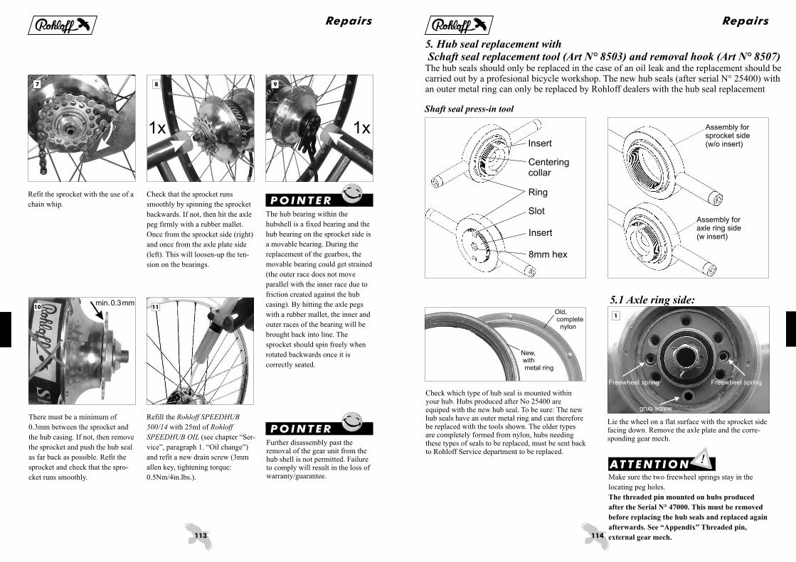
Refit the sprocket with the use of a
chain whip.
Refill the
with 25ml of
(see chapter “Ser-
vice”, paragraph 1. “Oil change”)
and refit a new drain screw (3mm
allen key, tightening torque:
0.5Nm/4in.lbs.).
Rohloff SPEEDHUB
500/14 Rohloff
SPEEDHUB OIL
Check that the sprocket runs
smoothly by spinning the sprocket
backwards. If not, then hit the axle
peg firmly with a rubber mallet.
Once from the sprocket side (right)
and once from the axle plate side
(left). This will loosen-up the ten-
sion on the bearings.
The hub bearing within the
hubshell is a fixed bearing and the
hub bearing on the sprocket side is
a movable bearing. During the
replacement of the gearbox, the
movable bearing could get strained
(the outer race does not move
parallel with the inner race due to
friction created against the hub
casing). By hitting the axle pegs
with a rubber mallet, the inner and
outer races of the bearing will be
brought back into line. The
sprocket should spin freely when
rotated backwards once it is
correctly seated.
There must be a minimum of
0.3mm between the sprocket and
the hub casing. If not, then remove
the sprocket and push the hub seal
as far back as possible. Refit the
sprocket and check that the spro-
cket runs smoothly.
P OI NTE R
Repairs
Further disassembly past theremoval of the gear unit from thehub shell is not permitted. Failureto comply will result in the loss ofwarranty/guarantee.
P OI NTE R
114
111
5.1 Axle ring side:
Assembly forsprocket side(w/o insert)
Assembly foraxle ring side(w insert)
Shaft seal press-in tool
Check which type of hub seal is mounted withinyour hub. Hubs produced after No 25400 areequiped with the new hub seal. To be sure: The newhub seals have an outer metal ring and can thereforebe replaced with the tools shown. The older typesare completely formed from nylon, hubs needingthese types of seals to be replaced, must be sent backto Rohloff Service department to be replaced.
Old,completenylon
New,withmetal ring
Centeringcollar
Ring
Insert
Slot
8mm hex
Insert
Lie the wheel on a flat surface with the sprocket sidefacing down. Remove the axle plate and the corre-sponding gear mech.
ATTE NT I ON
5. Hub seal replacement withSchaft seal replacement tool (Art N° 8503) and removal hook (Art N° 8507)
The hub seals should only be replaced in the case of an oil leak and the replacement should becarried out by a profesional bicycle workshop. The new hub seals (after serial N° 25400) withan outer metal ring can only be replaced by Rohloff dealers with the hub seal replacement
Make sure the two freewheel springs stay in the
locating peg holes.
The threaded pin mounted on hubs produced
after the Serial N° 47000. This must be removed
before replacing the hub seals and replaced again
afterwards. See “Appendix” Threaded pin,
external gear mech.
Freewheel spring
grub screw
Freewheel spring
Repairs

115
65
42 3
7
ATTE NT I ON
If the rub-ring of the axle ringshows signs of damage (grooveswithin the outer surface, noticablewith a fingernail), then please postthe axle ring to the Rohloff servicedepartment so that a new rub-ringcan be mounted.
Remove the old hub seal from thehub shell. To do this place the in-sert onto the hub and hook the re-moval tool under the old hub seal.Lever the removal tool into the up-right position as shown in the pic-ture.
Lay a 10mm wrench flat over theinsert with the open end hooked un-der the wooden grip of the removaltool. Secure the removal tool bypushing it against the insert. Forcethe wrench down onto the insert inorder to lever the removal toolwith the old hub seal upwards andout of the hub shell. Remove the in-sert.
Use a cottonbud to clean and de-grease (petroleum/brake cleaner)the mating surface ready for thenew hub seal.
Remove the old hub seal by shar-ply pulling the removal tool up-wards. If this doesn´t remove the se-al from the hub shell, then followthe method shown below.
Groove
Prepare the hub seal press tool asshown in the picture.
One threadvisible
Repairs
116
12
CenteringcollarZentrier-bund
8 9 10
11 13
Place the new hub seal around thecentering collar of the press tool.
The closed side of the new hub se-al faces towards the tool itself, theopen side is visible.
ATTE NT I O N
Using a cottonbud, cover theoutside edge of the new hub sealwith a thin coat of Loctite 641.
Make sure that none of the Loctitefinds its way into the groove of thenew hub seal.
Place the press tool onto the hubwith the new hub seal facing in-wards.
P OI NTE R
Thread the two included wingboltsthrough the square slots on opposi-te sides of the press tool, secure the-se in the holes of the hub left andright of the axle. Turn the press tool clockwise as far
as possible whilst holding theinsert still with an 8mm allen key.The new hub seal will now bepressed firmly into the correctposition.
Wind the press tool back to its nor-mal position. Remove the presstool and wing bolts. Clean awayany Loctite that has overspilled on-to the hub shell.
The grub screw on hubs after
Serial N° 47000 must be removed
in able to guarantee a flush
mounting of the Hub Seal.
P OI NTE R
Repairs

117
14 16
17 18 19
15
Replace the axle plate and the gearmech using new paper gaskets asshown in the Owners Manual.
Axle plate position
Internal gear mech
External gear mech
“Mounting 4”
“ Repair 1.1 + 1.2”
“Service 5.3”
Remove the sprocket as shown inthe Owners Manual. Lie the wheelon a flat surface with the sprocketside facing up
Oil could leak out once the spro-cket is removed.
(Service5.3)
ATTE NT I ON
5.2 Sprocket side:
Check the sprocket for signs of we-ar. If it is worn then rotate it beforeremounting (see Owners Manual).When both sides are worn then re-place it for an unworn sprocketwith undamaged seal surfaces.
ATTE NT I ON
Remove the old hub seal from thehub shell. To do this place the spro-cket tool onto the driver and hookthe removal tool under the old hubseal. Lever the removal tool intothe upright position as shown inthe picture.
Remove the old hub seal by shar-ply pulling the removal tool up-wards. If this doesn´t remove theseal from the hub shell, then fol-low the method shown below.
Lay a 10mm wrench flat over thesprocket tool with the open endhooked under the wooden grip ofthe removal tool. Secure the remo-val tool by pushing it against thesprocket tool. Force the wrenchdown onto the sprocket tool in or-der to lever the removal tool withthe old hub seal upwards and outof the hub shell. Remove the in-sert.
Groove
Repairs
118
20 21 22
23 24 25
Clean and degrease (petro-leum/brake cleaner) the mating sur-face ready for the new hub seal.
Place the new hub seal around thecentering collar of the press tool.The closed side of the new hub se-al faces towards the tool itself, theopen side is visible.
Using a cottonbud, cover theoutside edge of the new hub sealwith a thin coat of Loctite 641.
Make sure that none of the Loctitefinds its way into the groove of thenew hub seal.
ATTE NT I ON
Place the sprocket tool onto thedriver and se-cure it in positionwith the Q/R skewer or an axlenut. Set the ring over the sprockettool and thread it clockwise as faras pos-sible over the thread of thedriver whilst holding the sprockettool still with an 24mm wrench.The new hub seal will now bepressed firmly into the correctposition.
Remove the ring and the sprockettool.
Replace the new/rotated sprocket(with undamaged seal surfaces) asshown in the Owners Manual.
P OI NTE R
The metal part of the hub sealsshould be flush with the edge ofthe hub shell and/or hub cap
Repairs

119
Appendix
Trouble shooting
Problems and possible reasons Solution
1.
2.
3.
3.1
3.2
3.3
4.
4.1
see 2.
see 2
(14 gears = 13 clicks)
- Internal gear mech, see 7.2.1
- External gear mech, see 7.3.1
see 2.
see 3.2
see 2.
"Service"
"Service"
"Mounting"
"Mounting"
"Service"
"Riding with the SPEEDHUB 500/14"
"Service"
Too much play in the twist shifter
(more than 2mm)
Gear display is not aligned correctly
Twist shifter will not turn through all 14 gears
Twist shifter does not turn freely
Readjust the cable tension,
Alter the cable adjusters, .
Shifter cables cut at the wrong length Cut cables to the correct length:
Falsely altered cable adjusters Alter the cable adjusters,
For external gear mech: Correctly align the hexagonal peg
Hexagonal peg of the gear transfer box in
an incorrect position
Cable tension is too high Reduce the shifter cable tension,
Check the internal gear mech:
Open the bayonet connectors and (holding a cable
in each hand) pull the cables in turn. They run
smoothly, see points 4.2 - 4.6. They do not run
smoothly, see point 4.7.
Check the external gear mech:
Select gear #14. Remove the cable box just enough
so that the twist shifter can be turned without force
and the cables keep their normal routing bends.
Turn the twist shifter back and forth. It does not
turn smoothly, see points 4.2 - 4.6. It turns
smoothly, see point 4.8.
120
Appendix
}Problems and possible reasons Solution
4.2
4.3
4.4
4.5
4.6
4.6.1
4.7
4.8
4.8.1
4.9
4.9.1
Shifter cables worn, dirty or damaged
Incorrect shifter cables fitted
(not orginal
Fit new shifter cables:
Cable routing has too many bends or kinks - Internal gear mech, see 7.2
- External gear mech, see 2.
Inner nylon liners have penetrated into the
twist shifter or the cable box
(due to a false fitment)
Twist shifter rubs against the grip itself Leave a small gap between the twist shifter and the
Twist shifter degreased by weather Remove the twist shifter grip rubber, clean it, and
regrease it. See .
Hub cable broken and frayed Check the shifter cables:
Loosen the concertina tubes at the hub and pull
them up towards the bayonet connectors. Check the
condition of these cables in gear positions 1 and 14.
If the hub cable is damaged, it will need replacing:
- One-piece axle ring, see 1.1
- Quick-change axle ring, see 1.2
Gear transfer box (external gear mech) is bent Replace the gear transfer box
Mounting, see 5.3
Changing between gears 8 and 14 is not Grub screw (after hub Nr 47000 with an external
possible or only possible with extreme force gear mech) is threaded too far into the axle. This must
be unscrewed approx. 2mm. See .
Hexagonal peg of the external gear mech does Checking:
not turn freely (due to corrosion) Place an 8mm wrench over
the hexagonal peg of the external transfer box.
When using the wrench to switch gears, the
changing of gears must have a light and positive
feel. If not, remove the external transfer box.
Regrease the hexagonal peg and the sprocket
.
The cable pulley of the external gear mech Check:
doesn´t turn freely (after the conversion from The correct position of the cog over the hexagonal
an internal to an external gear mech) peg . See
Rohloff)
"Mounting"
"Service"
“Repairs” 3
"Repairs"
"Repairs"
"Service"
“Appendix”
("Service" 5.3)
“Service” 5.3
grip or insert a teflon washer between the two parts.
D
E
121
Appendix
Problems and possible reasons Solution
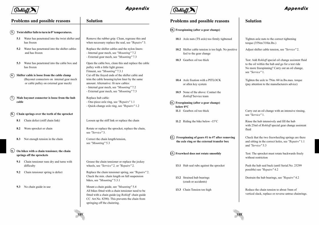
5. .
5.1
5.2
5.3
6 Shifter cable is loose from the cable clamp
7. Male bayonet connector is loose from the hub
cable
8. Chain springs over the teeth of the sprocket
8.1
8.2
8.3
9. On bikes with a chain tensioner, the chain
springs off the sprockets
9.1
9.2
9.3
see 3.
:
- Internal gear mech, see 7.2
- External gear mech, see 7.3
see 7.3.1
. Cut off the frayed ends of the shifter cable and
(Bayonet connectors on internal gear mech trim the cable housing/nylon liner by the same
or cable pulley on external gear mech) amount. Alternative: fit new cables:
- Internal gear mech, see 7.2
- External gear mech, see 7.3
Replace hub cable:
- One-piece axle ring, see 1.1
- Quick-change axle ring, see 1.2
Chain defect (stiff chain link) Loosen up the stiff link or replace the chain
Worn sprocket or chain Rotate or replace the sprocket, replace the chain,
see 3.
Not enough tension in the chain Correct the chain length/tension,
see 5.3
Chain tensioner runs dry and turns with Grease the chain tensioner or replace the jockey
difficulty wheels, see 2. or 2.
Chain tensioner spring is defect Replace the chain tensioner spring, see 2.
Check the min. chain length on full suspension
bikes, see 5.3.1
No chain guide in use Mount a chain guide, see 5.4
All bikes fitted with a chain tensioner need to be
fitted with a chain guide (eg chain guide
CC Art.No. 8290). This prevents the chain from
springing off the chainring.
"Repairs"
"Mounting"
"Mounting"
"Mounting"
"Mounting"
"Mounting"
"Repairs"
"Repairs"
"Service"
"Mounting"
"Service" "Repairs"
"Repairs"
"Mounting"
"Mounting"
Rohloff
Twist shifter fails to turn in 0° temperatures
Water has penetrated into the twist shifter and Remove the rubber grip. Clean, regrease this and
has frozen when necessary replace the seal,
Water has penetrated into the shifter cables Replace the shifter cables and the nylon liners
and has frozen
Water has penetrated into the cable box and Open the cable box, clean this and replace the cable
has frozen pulley with a little light grease.
Fitment,
122
Appendix
Problems and possible reasons Solution
10. Freespinning (after a gear change)
10.1
10.2
10.3
10.4
10.5
11. Freespinning (after a gear change)
below 0°C
11.1
11.2
12. Freespinning of gears #1 to #7 after removing
the axle ring or the external transfer box
13. Freewheel does not rotate smoothly
13.1
13.2
13.3
Axle nuts (TS axle) too firmly tightened Tighten axle nuts to the correct tightening
torque (35Nm/310in.lbs.)
Shifter cable tension is too high. No positive Adjust shifter cable tension, see 2.
feel to the gear change
Gearbox oil too thick Test: Add special oil change assistent fluid
to the oil within the hub and go for a test ride
No more freespinning? Carry out an oil change,
see 1.
None of the above: Contact the
Service team
Gearbox oil too thick Carry out an oil change with an intensive rinsing,
see 1.
Riding the bike below -15°C Rinse the hub intensively and fill the hub
with 25ml of special gear change assistent
fluid
Check that the two freewheeling springs are there
and sitting in the correct holes, see 1.1
and 5.3
Test: The sprocket must rotate backwards freely
without restriction
Hub seal rubs against the sprocket Push the hub seal back (until Serial.No. 25299
possible) see 4.2
Strained hub bearings Destrain the hub bearings, see 4.2
(crash or accidents)
"Service"
Rohloff
"Service"
Rohloff
"Service"
Rohloff
"Repairs"
"Service"
"Repairs"
"Repairs"
Axle fixation with a PITLOCK Tighten the axle to 7Nm /60 in.lbs.max. torque
or allen key system (pay attention to the manufacturers advice)
Chain Tension too high Reduce the chain tension to about 5mm of
vertical slack, replace or reverse untrue chainrings.

123
Appendix
Too much oil within the gearbox increases the risk of oil leaks. Therefore, when an oil leak is discovered, new
replacement oil must not be added (risk of overfilling). Reduced oil level by leakage through the seals will not
cause problems and riding further until the next oil change (annually or every 5000km) is possible (see
1.)."Service"
ATTE NT I ON
Problems and possible reasons Solution
14. Oil leaks
14.1
14.2
14.3
14.4
14.5
14.6
14.7
14.8
15. C
Oil traces (no droplets) This is not an oil leak. This is sweat oil, which
forms around the hub bearing, the paper gasket and
the oil drain screw due to variations in air
temperature and pressure.
Oil leaks following horizontal transportation See
Oil traces on the quick release skewer The ventilation functions through the axle hole for
the quick release skewer. Oil traces on the quick
release skewer are, therefore, normal
Oil drops out of the hollow quick release axle Please contact the Service team
Oil droplets on the axle ring, the axle plate or Check the axle plate screws are all in place and
the concertina tubes tightened to the correct tightening torque. (see
4.3) Renew the paper gaskets between
the axle ring and the axle (see 5.3 or
1.1) Only use axle plate screws
with thread sealant
Oil droplets between the hub casing and the Check the hub cap screws are all in place and
hub cap tightened to the correct tightening torque,
see 4.2
Oil traces around the oil drain screw Use new thread sealant on the oil drain
screw (Loctite thread sealant 511) or a new oil
drain screw with thread sealant,
see 1.
Oil droplets on the hub bearings Please contact the Service team
(Both ends of the hub smeared with oil)
The (mounted in hubs after No 47000
with an external gear mech) is screwed too far into
the axle. This must be unscrewed approx. 2mm.
See , G external gear mech.
"Riding with the SPEEDHUB 500/14"
Rohloff
"Mounting"
"Service"
"Repairs" Rohloff
"Repairs"
Rohloff
"Service"
Rohloff
“Appendix”
omplete blockage of the gear system after
working on the external gear mech
grub screw
rub screw
124
Appendix
Tools and bolts
Below is a list of all tools and bolts (along with their corresponding tightening torques) for the mounting of the
Rohloff SPEEDHUB 500/14 and all of its accessories.
* The use of Torx screws/bolts as opposed to thecommon allen key bolts allows a more safe andnondestructive mounting and dismounting with-out the heads rounding out after several timesusage. To avoid damaging the heads of thescrews/bolts, the Torx key must be securelypressed into the head. We suggest the use of a T-grip key to keep the pressure central over thebolt (the use of other tools could result indamage to the bolts).
P OI NTE R
Torx TX20 wrench (Art.Nr. 8504)*
2
3
4
5mm allen key
Rohloff SPEEDHUB 500/14:
External gear mech:
Twist shifter:
Rohloff chain tensioner/DH chain tensioner:
External gear mech:
Rohloff SPEEDHUB 500/14:
Rohloff SPEEDHUB 500/14:
TS versions:
Rohloff SPEEDHUB 500/14:
Retrofit versions (not OEM or OEM2):
Rohloff chain tensioner/DH chain tensioner:
8 Hub cap screws: M4 10 (3Nm/25in.lbs.)
5 or 6 Axle plate screws: M4 25 (3Nm/ )
2 Cable box cover bolts: M4 10 (3Nm/ )
Bolt (rear distance bush): M4 20
Bolt : M4 35
2 Clamp bolts: M4 35
8 Bayonet connector bolts: M4 4 (1.5Nm )
2 Cable pulley bolts: M4 4
3 Mounting bolts: M4 8
Oil drain screw (0,5Nm )
Cable guide mounting bolt: M6 (6Nm )
2 Mounting bolts: M6 25
4 or 5 Chainring bolts: M8 (7Nm )
4 brake disc mounting bolts: M8 0.75 (
x
x
x
x
x
x
x
x
x
x
x
25in.lbs.
25in.lbs.
2 Guide pin bolts: M4 (3Nm/25in.lbs.)
2 Cable guide bolts: M4 16 (3Nm/25in.lbs.)
2 End stop bolts (DH: just one): M4 10 (3Nm/25in.lbs.)
Jockey wheel axle bolt: M4 (3Nm/25in.lbs.)
(3Nm/25in.lbs.)
Bolt (rear threaded bush): M4 20 (3Nm/25in.lbs.)
(rear threaded bush) (3Nm/25in.lbs.)
(3Nm/25in.lbs.)
/12in.lbs.
(1.5Nm/12in.lbs.)
(1.5Nm/12in.lbs.)
Oil drain screw (0,5Nm/4in.lbs.)
/4in.lbs.
/51in.lbs.
Torque arm clamp bolt: M6 12 (6Nm/51in.lbs.)
8 0.75 /61in.lbs.
7Nm/61in.lbs.)
2 Torque arm mounting bolts: M8 (7Nm/61in.lbs.)
Mounting bolt (8Nm/70in.lbs.)
Pivot axle (8Nm/70in.lbs.)
(Attention: Turning clockwise unscrews)
Rohloff chain guide CC:
Internal gear mech:
Rohloff DH chain guide:
Rohloff SPEEDHUB 500/14:
Rohloff SPEEDBONE:
DB versions:
x
x
x
x
x
mm allen key
2.5mm allen key
mm allen key
mm allen key
7mm wrench
8mm wrench
10mm wrench
mm wrench
Screw driver
mm wrench
mm wrench
Sprocket tool (Art.No. 8501)
Chain whip
Brass tube 165mm (Art.No. 8711)
Brass tube 200mm (Art.No. 8712)
Shifter cable measurement tool (Art.No. 8506)
Rohloff chain guide CC:
TS versions:
Cable guide straight type
CC versions:
M4 Nut, rear distance bush
Shifting shaft
Torque arm clamp nut
Frame clamp nut
2 clamps (5Nm/43in.lbs.)
Sprocket removal
Sprocket removal
Cutting hub cables (internal gear mech)
Cutting shifter cables (external gear mech)
Cutting shifter cables (internal gear mech)
13mm wrench
15
17
24
Internal gear mech:
TS versions:
Cable guide
2 TS axle nuts: M10 (35Nm/310in.lbs.)
Locking nut (holding the axle steady)
for sprocket tool

125
1 2
4 5
2 31
423 1
21
21
3
231
4
12
3
Start to lace up the wheel from the
hubcap side of the hub. The first
leading spoke should be inserted
from the inside of the hub flange
behind a hubcap screw (spoke he-
ad facing inwards).
The end of this spoke should be in-
serted into the nipple hole of the
rim that is 4 holes away from the
valve hole.
Three holes (one hole) behind this
first spoke is where the trailing spo-
ke should be inserted, this spoke is
to be inserted from the outside of
the hub flange (spoke head facing
outwards). This spoke is to be cros-
sed over the first spoke and inser-
ted into the nipple hole of the rim
that is two holes before that of the
first spoke.
The valve hole is to be found oppo-
site from a hubcap screw. The spo-
ke hole of the flange opposite from
this is where the first spoke on the
sprocket side is to inserted from
the inside (spoke head facing in-
wards). This spoke is to be inserted
into the nipple hole of the rim that
is 3 holes behind the valve hole.
Lace all the remaining spokes in
the same pattern as with the other
side of the wheel (Pic 3 and 4).
The next trailing and leading spo-
kes are laced into the rim in exact-
ly the same way. The only differ-
ence being that they enter the hub
flange two holes away from the
last respective leading or trailing
spoke, and that they enter the rim
four holes away from the last re-
spective spokes. Continue this pro-
cess in pairs of leading and trailing
spokes until all the spokes have
been laced into the hubcap side of
the wheel. Turn the wheel over.
Wheel lacing for rims
with a European spoke-
hole pattern
The following written wheel lacing
method always concentrates itself
around the directional rotation of
the wheel, the method also only ap-
plies to wheels with a two cross la-
cing pattern. For simple one cross
lacing patterns, pay attention to the
numbers in brackets.
Front
Valve hole
Firstsprocketside spoke
Hubcapscrew
Leadingspoke(inwardhead)
Trailingspoke(outwardhead)
Leadingspoke(inward head)
Appendix
Front Front
Front
P OI NTE R
Trailing spokes cross in front ofLeading spokes.Leading spokes cross behind theTrailing spokes.
126
1 2
4 5
2 31
4
23
1
21
3
1
23
1
21
Start to lace up the wheel from the
sprocket side of the hub. The first
trailing spoke should be inserted
from the outside of the hub flange
opposite a hubcap screw (spoke he-
ad facing outwards).
The end of this spoke should be in-
serted into the nipple hole of the
rim that is 3 holes away from the
valve hole.
Three holes (one hole) behind this
first spoke is where the leading spo-
ke should be inserted, this spoke is
to be inserted from the inside of
the hub flange (spoke head facing
inwards). This spoke is to be cros-
sed over the first spoke and inser-
ted into the nipple hole of the rim
that is two holes behind that of the
first spoke.
The valve hole is to be found oppo-
site from a hubcap screw. The spo-
ke hole of the flange that is two ho-
les behind this, is where the first
spoke on the hubcap side is to be
inserted from the outside (spoke he-
ad facing outwards). This spoke is
to be inserted into the first nipple
hole of the rim that lies behind the
valve hole. Lace all the remaining
spokes in the same pattern as with
the other side of the wheel (Pic 3
and 4).
The next trailing and leading spo-
kes are laced into the rim in exact-
ly the same way. The only differ-
ence being that they enter the hub
flange two holes away from the
last respective pull or cross spoke,
and that they enter the rim four ho-
les away from the last respective
spokes. Continue this process in
pairs of leading and trailing spokes
until all the spokes have been laced
into the sprocket side of the wheel.
Turn the wheel over.
Wheel lacing for rims
with a French spoke-hole
pattern
The following written wheel lacing
method always concentrates itself
around the directional rotation of
the wheel, the method also only ap-
plies to wheels with a two cross la-
cing pattern. For simple one cross
lacing patterns, pay attention to the
numbers in brackets.
Hubcapscrew
Front
Valve hole
Firsthubcap
side spoke
Leadingspoke(inwardhead)
Trailingspoke(outwardhead)
Trailingspoke(outwardhead)
Appendix
FrontFront
Front
P OI NTE R
Trailing spokes cross in front ofLeading spokes.Leading spokes cross behind theTrailing spokes.

127
Appendix
Technical data
Number of gears: . . . . . . . . . . . . . . . . . . . . . . . . . . . . . . . . 14Gear increases: . . . . . . . . . . . . . . . . . . . . . . . . . . . . . . . . . even 13.6%Range of gears: . . . . . . . . . . . . . . . . . . . . . . . . . . . . . . . . . 526%
Frame spacing: . . . . . . . . . . . . . . . . . . . . . . . . . . . . . . . . . 135mmNumber of spoke holes: . . . . . . . . . . . . . . . . . . . . . . . . . . . 32Spoke flange distance: . . . . . . . . . . . . . . . . . . . . . . . . . . . . 60mm, symmetricalSpoke hole circle diameter: . . . . . . . . . . . . . . . . . . . . . . . . Ø100mmSpoke hole diameter: . . . . . . . . . . . . . . . . . . . . . . . . . . . . . Ø2.7mm
Axle overall width CC: . . . . . . . . . . . . . . . . . . . . . . . . . . . 147mmHollow axle inner diameter:. . . . . . . . . . . . . . . . . . . . . . . . Ø5.5mm, for quick release lever
Mounting bolt hole circle diameter: . . . . . . . . . . . . . . . . . . Ø65mmBrake disc mounting bolts:. . . . . . . . . . . . . . . . . . . . . . . . . 4 M8 0.75Distance between dropout and center disc mount: . . . . . . . 15.3mm (IS2000)
Weight: . . . . . . . . . . . . . . . . . . . . . . . . . . . . . . . . . . . . . . . 1700g (CC), 1800g (CC EX), 1825g (CC DB)Oil amount: . . . . . . . . . . . . . . . . . . . . . . . . . . . . . . . . . . . . 25ml max.
Number of sprocket teeth: . . . . . . . . . . . . . . . . . . . . . . . . . 16 (optional: 13, 15 and 17)Chainline: . . . . . . . . . . . . . . . . . . . . . . . . . . . . . . . . . . . . . 54mm (58mm with 13tooth sprocket)Smallest permittable gear ratios (normal): . . . . . . . . . . . . . 40/17, 38/16, 36/15, 32/13 (transmission ratio ~2.35)(Riders over 100kg/tandem): . . . . . . . . . . . . . . . . . . . . . . . 42/17, 40/16, 38/15, 34/13 (transmission ratio ~2.50)Maximum input torque: . . . . . . . . . . . . . . . . . . . . . . . . . . . 100Nm
Gear control: . . . . . . . . . . . . . . . . . . . . . . . . . . . . . . . . . . . by twist shifterTwist shifter angle per gear change: . . . . . . . . . . . . . . . . . . 21°Gear control transfer: . . . . . . . . . . . . . . . . . . . . . . . . . . . . . over two shifter cables (pull-pull system)Shifter cable movement per gear change: . . . . . . . . . . . . . . 7.4mm
Inner gear ratios (hub rotation per sprocket rotation):
1: 0.279
Spoke flange width: . . . . . . . . . . . . . . . . . . . . . . . . . . . . . . 3.2mm
Axle diameter at dropout:. . . . . . . . . . . . . . . . . . . . . . . . . . 9.8mm
Axle overall width TS: . . . . . . . . . . . . . . . . . . . . . . . . . . . . 171mm (with axle plate TS long 179mm)Axle thread TS: . . . . . . . . . . . . . . . . . . . . . . . . . . . . . . . . . M10 1
Center disc mounting diameter: . . . . . . . . . . . . . . . . . . . . . Ø52mm
Sprocket thread:. . . . . . . . . . . . . . . . . . . . . . . . . . . . . . . . . M34 6 P6, tolerance 6HSprocket type: . . . . . . . . . . . . . . . . . . . . . . . . . . . . . . . . . . for bicycle chain 1/2 3/32” (ISO Nr. 082)
Gear #Gear #2: 0.316Gear #3: 0.360Gear #4: 0.409Gear #5: 0.464Gear #6: 0.528Gear #7: 0.600Gear #8: 0.682Gear #9: 0.774Gear #10: 0.881Gear #11: 1.000Gear #12: 1.135Gear #13: 1.292Gear #14: 1.467
We reserve the right to change the technical specifications without prior warning
x
xx
x x
.
128
Appendix
Consecutive Serial N° - Production Year000000 000300...............1998000301 002415 1999002416 005502 2000005503 - 010812 2001010813 - 017603 2002017604 - 027008 2003027009 - 037183 2004037184 - 050049 2005050050 - 064512...............2006064513 - 080499...............2007080500 ~______...............2008
-- ...............- ...............
...............
...............
...............
...............
...............
P OI NTE R G ua r a n t y Ca r d
T I P S t i c k e r
ATTE NT I ON S e r i a l N um b e r
Each is provided with a. which is found on the tape around
the hub shell.
Rohloff SPEEDHUB 500/14consecutive Serial N°
Each and each complete bicycleequiped with the comes complete withan orange warranty card attached.
This orange warranty card
- completely filled in (with Serial N°.!)- stamped by the dealer- returned to , Germany
SPEEDHUB 500/14SPEEDHUB 500/14
Rohloff
Rohloff
Rohloff AG
must be:
Only with this original Rohloff warranty card we can guarantee the best service for your hub.
This serial-No informs us about the production year and isimportant for guarantee or warranty claims, as well as a actingas proof of ownership.
Only with knowledge of the appropriate serial-No can anoptimal service can be carried out by Rohloff.
If the tape around the hub shell should be removed at any time, we recommend to separate first the with asharp carpet knife from the tape and then to leave only the SerialN° on the hub. If the tape should be removedcompletely, the should be saved and/or stuck onto the warranty card. Alternatively, the canalso can be engraved on the hub cap!
Serial N°
Serial N° Serial N°
We expressively point out that the does forgearhubs
Rohloff AG RohloffSPEEDHUB 500/14
not accept any warranty/warranty claimswithout a Serial N°. Service, repairs, and the spare parts service will also only
be carried out on hubs when the hub is shown with the corresponding Serial N° (either on the sticker, engravedinto the hub shell, or on the guarantee card).
RohloffAGService Team
Reference to Serial N° of the Rohloff SPEEDHUB 500/14
ATTENT I ON Wa r r a n t y
003005
Onwards of Serial N° 75000, the serial numbers areengraved directly onto the hub shell.

129
3
2mm
C
Appendix
Grub screw A
If the external gear mech should be falsely mounted, then the fitting of an axle plate screw into hole ( ) wouldcause the grub screw ( ) to be forced into the axle. This in turn will lead to a complete blockage of the gearbox.
CA
To control that the mounting iscorrect, the screw ( ) must bescrewed smoothly approx. 4complete turns into the hubwithout force. Afterwards, theinstallation of the axle platecomplete with screws can befinished (3Nm).
C
The blind hole must be locateddirectly over the grub screw .When using an external gear mechwithout a blind hole( ), the grubscrew must be screwed flush intothe axle.
(B)(A)
B
The paper gaskets should thenbe fitted so that all the holesmeet up with the correspondingscrew holes of the axle.
The grub screw on hubs with aSerial No between 47000 and48500 lies flush (external gearmech without a blind hole).Onhubs with the Serial No 48501 andover, this grub screw pertrudes byapprox. 2mm (external gear mechwith a blind hole).
The removal of the grub screw is only necessary when converting the external to an internal gear mech, orwhen working with the hub seal replacement tools. The external gear mech should never be removed fromthe gearbox without good reason!
If an axle plate screw cannot or only with force be screwed into hole (C), then it must be checked that the grubscrew (A) is not sitting directly behind this hole. If this is the case, then the external gear mech must bedisassembled turned around 180° and mounted again in this position. The grub screw stays in its original position(2mm pertruding).
Grub screw of the External Gear Mech
All gear hubs built after Serial No 47000 and equiped with an external gear mech have an M4x8 grub screw mountedinto the sixth threaded hole of the axle (it helps to prevent potential oil leaks).Therefore, the external gear mech canonly be properly fitted in one position (Pic 2) over the axle.
P OI NTE R
ATTE NT I ON
blindhole B
Grubscrew A
130
Notes

131
Notes
T I P -Owners Manual --Films-Technology Presentation CD
Newest version
This Owners Manual is also available in a variety of otherlanguages. Should you require a different version, you candownload it from our homepage under:
www.rohloff.de > download > description > owners manual
The following languages are available:
-English-German-French-Dutch
The newest version of this Manual is available on the web under:www.rohloff.de > download > description > owners manual
Further to the manual, the most important work, service and repairs on theSPEEDHUB 500/14 are shown in short films on the web.www.rohloff.de > videos > workshop ...
The technology Presentation CD explains the function and build of theSPEEDHUB 500/14 with the use of various animations and further in-depth
technical details
Rohloff
Rohloff(Art.N° 8296)
132
Index
Key word PageA Advantages of the options 38
Axle plate alignment 64
Axle plates 46
Axle ring - One-piece / Quick-change 98, 104
Axle types 24
B Bolt/tool info 124
Brake disc - replacement 60, 91
Brake discs / rotors 37
Break-in period 6
C Cable routing via the brake boss - Internal gear mech 76
Cable routing via the chainstay - External gear mech 80
Cable routing via the chainstay - Internal gear mech 79
Cable routing via the top tube - External gear mech 83
Carbon handlebars 48
Chain guide - DH (accessory for downhill) 45, 58
Chain guide - CC 71
Chain tensioner - DH (accessory for downhill) 45, 68, 69
Chain tensioner - mounting 70
Chain tensioner spring - changing 109
Chainguard enclosed 48
Chainring - two chainrings 45, 47
Cleaning the Rohloff SPEEDHUB 500/14 7
Colors 33
Comparison - Derailleur gears and Rohloff SPEEDHUB 500/14 21
Comparison to derailleur gears 22
Components that we recommend 45
Cranks, Crankset 45, 57
D Distance travelled per crank revolution (20", 26" and 28") 20
E Emergency repairs 10
External gear mech - grub screw 129
External gear mech - mounting 32, 93
External gear mech - OEM / OEM2 / long torque arm 63
F Failure Diagnosis 119
Filling with oil 84
Frame mounted gear box 47
Frame types - OEM / OEM2 / long torque arm 27-29
G Gear display 83
Gear mech - replacement 92
Gear unit - installation - removal 112, 111
Grub screw of the External gear mech 129
Guarantee information 1, 128
H Hub cable - replacement 97
Hub seal - replacement 114
I Index 132
Inner rim diameter - calculating 44
Internal gear mech 31
Internal gear mech - via brake boss / via chainstay 61, 62
L Long torque arm 56
M Maintenance and care 7, 8, 89
Mechanical efficiency - comparsion 18
Model codes - explanation 33
Model variations 39
Modular system 23
Mounting (CC / TS versions) with a long torque arm 65, 66
Mounting necessities OEM2 30
Mounting processes 49

133
Index
Key word PageN Noises 6
Notices 130
O OEM axle plate 67
OEM2 - mounting with a support bolt / SPEEDBONE 59
OEM2 axle plate 67
Oil change 7, 87
One-piece axle ring - removal 92
Options 38
P Package contents - checking 51
Particular components 45, 46, 47
Pushing the bike 6
Q Quick-change axle ring - removal 92
R Racing bike / drop handlebars 46
Reference to Serial N° 128
Removal of the wheel from the frame 13
Replacing the gear unit 92
Reversing / Replacing of the sprocket 90
Riding noises 6
Rims 46
Rubber grip - replacement 110
S Safety information 3
Schlumpf Speed-drive, High Speed-drive 47
Securing to the frame 23-30
Serial N° - Pointers 128
Service procedures 96
Shifter - mounting 73
Shifter cables 75
Shifting gears 5
Small parts bag - checking the contents 53
Small wheels 47
Smallest permitted sprocket ratios 19
Special applications 47, 48
SPEEDBONE 46
Spoke length - calculating 42, 43
Spokes 46
Sprocket ratios - smallest 19
Sprocket reversing/replacement 90
Sprockets 45
Stand - axle mounted 47
T Tandem use 47
Technical data 17, 127
Tools and Bolts / Tools for the tour 124 , 9
Torque securing 25
Tour info 9
Trailer use 47
Transport - Info for the tour 9
Trouble shooting 119
Twist shifter - mounting 73
W Warranty information 1, 128
Wearable parts 6
Weight comparison 18
Wheel installation 14
Wheel lacing for rims with a European spoke hole pattern 125
Wheel lacing for rims with a French spoke hole pattern 126
Wheel removal (internal, external gear mech) 11
Wheel stability 41
Wheel lacing 55