1 Multiple Antenna Techniques for Wireless Mesh Networks
33
1 Multiple Antenna Techniques for Wireless Mesh Networks Athanasios Gkelias and Kin K. Leung Department of Electrical and Electronic Engineering Imperial College South Kensington Campus, London SW7 2AZ,UK. Email:{a.gkelias,kin.leung}@imperial.ac.uk 1.1 Introduction Wireless mesh networks (WMNs) is a relatively new and promising key tech- nology for next generation wireless networking that have recently attracted both the academic and industrial interest. Mesh networks are expected grad- ually to partially substitute the wired network infrastructure functionality by being able to provide a cheap, quick and efficient solution for wireless data networking in urban, suburban and even rural environments. Their popularity comes from the fact that they are self-organized, self-configurable and easily adaptable to different traffic requirements and network changes. Mesh net- works are composed of static wireless nodes that have ample energy supply. Each node operates not only as an conventional access point (AP)/gateway to the internet but also as a wireless router (Fig. 1.1) able to relay packets from other nodes without direct access to their destinations [1][2]. The destination can be an internet gateway or a mobile user served by another AP in the same mesh network. Moreover, some nodes may only have the backhauling functionality, meaning that they do not serve any mobile user directly but their purpose is to forward other APs’ packets. For wide area access, the access points (or base stations) are typically lo- cated at high towers or at the rooftop of buildings. However, as the capacity demands increase, the AP is moving closer to the user and it could be placed at below-the-rooftop heights. In this way it can provide better signal reception and higher spatial frequency reuse factor. For a cellular network point of view this means that the cell size has to shrink in order to satisfy the increased capacity demands. Therefore, the whole network topology in terms of base station location has to be revised and additional base stations have to be in- stalled by the network operator. In case where fiber is not readily available, the cost of backhauling by using e.g. E3 lines may be prohibitive for the operator. Wireless mesh networks can be proven an appealing alternative backhauling solution in this case since they do not require wired connection, they are easy
Transcript of 1 Multiple Antenna Techniques for Wireless Mesh Networks
1
Multiple Antenna Techniques for WirelessMesh Networks
Athanasios Gkelias and Kin K. Leung
Department of Electrical and Electronic EngineeringImperial CollegeSouth Kensington Campus, London SW7 2AZ,UK.Email:{a.gkelias,kin.leung}@imperial.ac.uk
1.1 Introduction
Wireless mesh networks (WMNs) is a relatively new and promising key tech-nology for next generation wireless networking that have recently attractedboth the academic and industrial interest. Mesh networks are expected grad-ually to partially substitute the wired network infrastructure functionality bybeing able to provide a cheap, quick and efficient solution for wireless datanetworking in urban, suburban and even rural environments. Their popularitycomes from the fact that they are self-organized, self-configurable and easilyadaptable to different traffic requirements and network changes. Mesh net-works are composed of static wireless nodes that have ample energy supply.Each node operates not only as an conventional access point (AP)/gateway tothe internet but also as a wireless router (Fig. 1.1) able to relay packets fromother nodes without direct access to their destinations [1][2]. The destinationcan be an internet gateway or a mobile user served by another AP in thesame mesh network. Moreover, some nodes may only have the backhaulingfunctionality, meaning that they do not serve any mobile user directly buttheir purpose is to forward other APs’ packets.
For wide area access, the access points (or base stations) are typically lo-cated at high towers or at the rooftop of buildings. However, as the capacitydemands increase, the AP is moving closer to the user and it could be placedat below-the-rooftop heights. In this way it can provide better signal receptionand higher spatial frequency reuse factor. For a cellular network point of viewthis means that the cell size has to shrink in order to satisfy the increasedcapacity demands. Therefore, the whole network topology in terms of basestation location has to be revised and additional base stations have to be in-stalled by the network operator. In case where fiber is not readily available, thecost of backhauling by using e.g. E3 lines may be prohibitive for the operator.Wireless mesh networks can be proven an appealing alternative backhaulingsolution in this case since they do not require wired connection, they are easy

2 Athanasios Gkelias and Kin K. Leung
Fig. 1.1. Conceptual illustration of a multi-hop wireless mesh network.
to deploy fast and without extensive network planning requirements since theyare self configurable and adaptable to network changes and demands. For in-stance, Multi-Element Multihop Backhaul Reconfigurable Antenna Network(MEMBRANE) [3] is an IST-funded project that aims to bring an efficientwireless backhaul design as an alternative technology to serve wireless broad-band networks in cases where a wired backhaul would be more costly to accessand/or would take longer to deploy.
Moreover, wireless mesh network can enhance the presence of broadbandin rural and remote zones, thus helping combat the “digital divide” betweenthese areas and the big urban centers, caused mainly by the inadequacy (oreven absence) of wired network infrastructure. It is not only doubtful that therequired investment for bringing cable and/or fiber will ever pay for itself insuch remote zones and communities but, more importantly, such an under-taking will probably take several years. Wireless mesh networks can providea quick and economically affordable solution in this case.
Technology enablers: Mesh networks must meet a number of technical re-quirements. First of all, they must meet the high capacity needs of the accessnodes which have to forward the accumulated traffic of their underling users.Furthermore, they have to cope with the delay and other strict quality-of-service (QoS) requirements of the end user applications. Finally they mustprovide a large enough effective communication range to ensure that no APs

1 Multiple Antenna Techniques for Wireless Mesh Networks 3
(or groups of APs) are isolated from the Internet gateways. In order to satisfythe above requirements, a range of novel techniques has to be exploited. Suchtechnology enablers include but not limited to multi-hopping, various multi-ple antennas techniques and novel medium access control (MAC) and routingalgorithms.
Multi-hopping, i.e. the use of multiple relays (or forwarding nodes) betweenthe end user and the Internet gateway, is primarily motivated by the lowpower and the low heights of the access and relay nodes. Clearly, in low powertransmissions, multi-hopping helps increase the range. Moreover, since lowheight access points are likely to be surrounded by several obstacles (buildings,cars, etc.), their line-of-site (LOS) will be typically obstructed, affecting in thisway the one-hop node connectivity to a gateway.
Multiple antenna techniques (also known as smart antennas) constituteanother enabling technology that is highly beneficial to the wireless mesh net-work architectures. These techniques include fixed beam antennas, adaptiveantennas and multiple-input multiple-output (MIMO) coding [4][5]. Depend-ing on the used technique, multiple antennas can provide power, diversityand multiplexing gain and therefore increase the transmission range, reducethe transmitting power, mitigate interference, increase channel reliability andincrease data throughout. Each of these techniques is more appropriate in dif-ferent types of propagation scenarios; for example beamforming is well suitedto cases with narrow angle spread, such as in high towers; whereas MIMOis more appropriate in cases of rich electromagnetic scattering, such as inlow-height links without strong LOS component.
Given the different types of propagation environments that are expectedin wireless mesh networks, smart antenna techniques are expected to boostthroughput performance and reduce interference and delay, thus improvingoverall end-to-end performance. However, multiple antenna techniques havebeen extensively analyzed only for single-link communications. The combina-tion of multi-hopping with multiple smart antennas in a wireless mesh networkenvironment is a field that has not received much research attention. Thiscombination is expected to boost network capacity and achieve the targetQoS.
Novel medium access control and routing algorithms that are able to ex-ploit the benefits of multiple antenna usage on the wireless mesh access pointsis another enabling technology of paramount importance. Employment ofsmart antennas techniques without thorough understanding and considera-tion of their interaction with layer two and three algorithms can be provencounter productive for the mesh network functionality. Deafness, hidden andexposed terminals and multi-stream interference are some of the problemsthat have to be addressed by novel MAC and routing schemes since theycan highly affect not only the individual links but also the overall networkperformance.
The main aim of this chapter is to give an insight into both the improve-ments and various challenges generated by the deployment of multiple anten-
4 Athanasios Gkelias and Kin K. Leung
nas in wireless mesh networks and how these can be addressed by layer twoand three algorithms. In the rest of this chapter the wireless mesh networkand channel characteristics are discussed in section 1.2. A thorough analy-sis of the various smart antenna techniques and their main advantages anddisadvantages follows in section 1.3. In section 1.4, the challenges that smartantenna techniques will impose to medium access control and network lay-ers are introduced together with some possible solutions. Finally, sections 1.5and 1.6 discus several scheduling and routing schemes respectively with smartantenna considerations.
1.2 Channel characteristics
The wireless channel in a mesh network is expected to be highly dynamic.The dynamic nature of the channel comes both from environmental changes/movements and from the interference fluctuations from network transmissions.In this chapter, we consider only the access point (AP) to AP communication(rather than the AP to user communication); therefore, we do not expectto have any explicit mobility in terms of transmitter or receiver movement.Nevertheless, the wireless mesh networks are expected to be deployed in urbanor suburban environments where the surrounding objects (cars, trains, andpeople) may be in constant move. Also nodes failure can affect the networkconnectivity by causing to higher layers similar effects as node mobility.
1.2.1 Propagation scenarios
Unlike legacy cellular networks, where base stations are exclusively mountedon high towers or at the rooftops of tall buildings after extensive networkplanning, aiming for high LOS coverage, wireless mesh APs can be less neatlydeployed. In order to reduce the deployment cost and being closer to theusers, the APs and relay nodes are mostly placed at low-to-moderate heights,in order of 3-10m (for example mounted on electrical and telephone poles,traffic lights, building sidewalls and rooftops) where direct LOS is difficultto be guaranteed. Depending on the relative position of the AP we can havedifferent communication scenarios that highly affect the channel propagationstatistics [3]:
Rooftop to rooftop: In this scenario both ends of a link are placed abovethe rooftop level. Pure LoS conditions are met as far as the first Fresnel zoneis clear.
Below-rooftop to below-rooftop: This refers to the case where bothnodes are deployed below the level of the surrounding buildings and it coversboth LoS and NLoS outdoor propagation conditions.
Rooftop to below-rooftop: In this scenario the one end of the link is lo-cated above the rooftop level while the other is below that. This case possessesstrong similarities with the traditional cellular case. The major difference is
1 Multiple Antenna Techniques for Wireless Mesh Networks 5
the Doppler spectrum shape and that the APs are placed at moderate height.Although LoS conditions are possible, the NLoS case is more probable.
Each scenario has an important impact in various channel properties, suchas path-loss, angle and delay spread and highly affect the optimum multipleantenna technique that should be used. For instance, at large scattering angles,MIMO performs better than adaptive beamforming techniques. However, atlow-moderate scattering angles adaptive or even some simple switched beamtechniques can be more beneficial than MIMO.
1.2.2 Power constrains
Since the mesh network transceivers are usually located on the top or side-walls of buildings or special contracted poles that have easy access to powerthrough wires, power supply and consumption is not a crucial issue for meshnetwork unlike sensor and mobile ad hoc networks. Moreover, since they arelocated close to the users, and for health and safety reasons, the wireless messtransceivers are expected to operate at relatively low powers (on the orderof at most a few Watts). Last but no least, total effective radiation powerlimitations may apply in different countries for directional transmissions inunlicensed bands (where a mesh network can operate) as it will be discussedin a latter section.
1.2.3 Interference characteristics
Inevitably, due to the spatial channel reuse in wireless mesh networks a givennode will suffer (co-channel) interference from other nodes making the wire-less communication more interference limited rather than noise limited. Inmultiple-antenna systems it is not only the signal-to-interference-ratio (SINR)that affects the network capacity but also the distribution of the interferencepower. In a mesh network, the interference is not spatially white but it willrather emanate unequally from different directions (spatial color). Recent re-sults in [6] and [7] shown that MIMO systems for a given SINR performmore efficiently the more spatially colored the interference is (i.e., it is bet-ter to have few and high-power interference components rather that many,low-power ones).
Moreover, in urban highways, big buildings in both sides act as naturalobstacles that can waveguide the signal and significantly reduce the interfer-ence from/towards adjacent streets. The degree that buildings and naturalobstacles can affect the signal propagation and reception highly depends onthe carrier frequency of the signal. These interference characteristics have tobe taken into account for the optimum design of wireless mesh network algo-rithms.

6 Athanasios Gkelias and Kin K. Leung
1.3 Smart antennas techniques
The use of intelligent antennas in ad hoc networks has recently attracted agreat amount of attention as a means to optimize power transmission/reception([8] and references therein). Two basic types of intelligent antennas are consid-ered in this context: directional antennas (fixed beams) and adaptive antennaarrays (also known as smart antennas). A directional antenna generates mul-tiple pre-defined fixed beam patterns and applies one at a time towards thedirection of interest. It is the simplest technique, essentially providing sec-torisation with the capability of illuminating the selected sector according to,for instance, an SNR-related metric. An adaptive antenna array can formu-late the beam structure based on a certain optimization criterion, such asmaximizing the array gain towards the signal of interest and suppressing in-terfering signals. MIMO techniques can be seen as an extension of adaptiveantenna arrays. They require multiple antennas at both end of the link andare capable to provide spatial multiplexing or diversity gain. In this section,we a) summarize the different multiple antenna techniques, b) give an insightinto the tradeoffs of the various performance gains they can achieve and c)discuss the cases (e.g. channel conditions, network requirements) that theirusage would be more appropriate.
1.3.1 Directional antenna techniques
Switched-beam antennas: Switched beam is the simplest technique. A pre-determined antenna array pattern or separate directive antennas are used togenerate a limited number of beams that point to desired directions. Thesebeams can be used either for transmission or reception and each time a beam-switching algorithm determines which particular beam will be used to main-tain the highest quality signal. The predefined beams can be switched in amechanical or electronic way. This ability to concentrate power in a certaindirection provides a directive gain (also called power gain or array gain) thatcan be used for extending range or reducing power. This type of antenna iseasy to be implemented (e.g. using multiple antenna elements, each pointingto different direction, where direction is chosen by choosing the element), butit gives a limited improvement.
Steered-beam antennas (or dynamically phased arrays): Steeredbeam antennas have also predefined patterns but they can be pointed to anyof a near continuous set of directions. This can be achieved by phase shiftingand combining the signals emitted from each element of an antenna array.Direction of arrival (DoA) techniques can be used to continuously track thedirection of the receiving signal and steer the beam accordingly [4]. This helpsto avoid the performance degradation occurred in switched beam antennas dueto “scalloping loss” [9] (the degradation due to scalloping loss is more signifi-cant in mobile environments rather than in static mesh networks). Although

1 Multiple Antenna Techniques for Wireless Mesh Networks 7
any arrangement of antennas can be used, the most typical would be linear,circular and planar arrays [12].
While directional antenna techniques can provide sufficient gain in termsof signal-to-noise ratio (SNR) in presence of strong line-of-sight componentand no interference, their performance deteriorates significantly in multi-pathenvironments where the desirable signal can arrive from multiple directions.
1.3.2 Adaptive antenna techniques
Adaptive antenna arrays, or smart antennas [10], use a combination of an arrayof multiple antennas and appropriate signal processing to produce desirableantenna patterns. Such patterns have high gain in the direction of desiredsignals and nulls in the direction of undesired signals.
Adaptive antenna arrays: Adaptive antenna array at the receiver canprovide power gain (array gain) by coherent combining the received signalcopies from all antenna elements. The effective total received signal powerincreases linearly with the number of antenna elements. Furthermore, its ra-diation patterns can be adjusted to null out the interference from other direc-tions [11]. In order to achieve this, intelligent digital signal processing (DSP)algorithms should be used [15] to estimate the DoA (several direction of arrivalestimation techniques such as ESPRIT [13] and MUSIC [14] can be used) ofall the impinging signals, both signal of interest and interfering signals. Inter-ference suppression is obtained by steering beam pattern nulls in the directionof the interfering signals while maintaining the main lobe in the direction ofthe desired signal. For an antenna array with N elements and for M inter-fering nodes (M < N), M nulls can be formed to eliminate the receivingpower of N separate interference while the remaining N − M antennas canbe used to beamform towards the direction of the desired signal. Finally, atthe transmitter side the adaptive array can form a narrow beam towards thedirection of the desired receiver while optimally suppresses the interferencetowards any other possible adjacent receivers.
MIMO techniques: MIMO systems can be viewed as an extension of thesmart antenna techniques described above. The main characteristic of MIMOtechniques is their ability to exploit multi-path propagation rather than mit-igate it. They take advantage of random channel fading and multi-path delayspread for multiplying transfer rates (multiplexing gain) or improve the trans-mission quality/reliability (diversity gain) at no cost of extra spectrum (onlyhardware and complexity are added). In this way it transforms a traditionallypitfall of wireless channel into a benefit of the communication system.
CSI : There is a large number of transmission and reception schemes overMIMO channels depending on the channel state information (CSI) available atthe transmitter and/or receiver side and on the diversity and/or multiplexinggain that has to be achieved. CSI at the receiver end (CSIR) can be obtainedfairly easy by sending a pilot symbol for channel estimation. At the transmitterside, channel state information (CSIT) can be obtained by CSIR transmission
8 Athanasios Gkelias and Kin K. Leung
from the receiver through a feedback channel. Alternatively, CSIT can be esti-mated in bi-directional systems without feedback by exploiting the reciprocalproperties of the channel. The former method introduces a trade-off betweenfeedback channel bandwidth and CSI accuracy while the latter one cannot beapplied in communication systems, such as frequency-division duplex (FDD)systems, where the reciprocal property does not hold.
Spatial diversity gain: Antenna diversity (or spatial diversity) can beachieved by placing multiple elements at the receiver and/or the transmit-ter. These antenna elements need to be placed sufficiently far apart such thatthe received signal replicas from different antenna elements fade more or lessindependently. In this case, there is a high probability that at least one ormore of these signal components will not be in a deep fade that reduces thevariance of the SNR. The required antenna separation depends on the localscattering environment as well as on the carrier frequency. The spatial diver-sity gain depends on the diversity order, which in turn depends on the degreeof which the multi-path fading on the different antenna elements is uncorre-lated. For M transmit and N receive antennas a maximum diversity gain ofMN can be achieved.
Transmit diversity can be achieved via space-time-coding (STC) schemes.The simplest STC scheme is the Alamouti scheme [16], designed for two trans-mit and two receive antennas without any feedback from the receiver and isone of the most popular techniques proposed in several third-generation cel-lular standards for transmit diversity. Space-time block coding (STBC), in-troduced in [17], generalizes the Alamouti scheme to an arbitrary number oftransmit antennas and is able to achieve the full diversity promised by thetransmit and receive antennas. At the receiver end linear processing maxi-mum likelihood (ML) decoding is used to decouple the signals transmittedfrom different antennas and perfect CSIR is assumed.
Spatial Multiplexing gain: In the presence of multi-path or rich scattering,a MIMO system can provide spatial multiplexing gain. This can be achievedby simply sending independent data streams over each of the transmit an-tenna elements. This technique is known as Vertical Bell Labs Space-TimeArchitecture (V-BLAST) [18] and it is the first spatial multiplexing techniqueimplemented in real-time in a laboratory. For M transmit and N receive anten-nas, and under fast fading channel conditions, min(M, N) independent datastream can be transmitted (often referred to as degrees of freedom (DOFs)).In slow fading channel though, the V-BLAST architecture is strictly subopti-mal. Another architecture, i.e., Diagonal Bell Labs Space-Time Architecture(D-BLAST) [19] can provide significant improvements by coding and inter-leaving the code-words across the antennas. However, the diagonal approachsuffers from certain implementation complexities. The receiver must multi-plex the signals in order to reconstruct the transmitting symbols. Maximumlikelihood (ML) decoding is an optimal solution in the sense that it comparesall the possible combinations of the symbols, but its complexity increaseswith the modulation order. Other popular techniques include zero forcing

1 Multiple Antenna Techniques for Wireless Mesh Networks 9
and minimum mean square error estimation combined with successive inter-ference cancelation (MMSE-SIC) [20]. Diversity and multiplexing gain can besimultaneously obtained for a given multiple-antenna channel, but there is afundamental tradeoff between how much each coding scheme can get [21].
1.3.3 Space-division multiple access (SDMA)
In a wireless network scenario with several nodes communicating to a commonreceiver, multiple receive antennas also allow the spatial separation of the sig-nals of different transceivers, thus providing a multiple-access gain. This useof multiple antennas is also called space-division multiple access (SDMA).The fact that a MIMO receiver can isolate and decode min(M,N) indepen-dent data streams (M transmit and N receive antennas), can be extendedto the case of single receiver employed with N antennas and M independenttransmitters with one antenna element. This can be generalized to the case ofseveral transmitters using overall M antenna elements in any possible combi-nation given that the received streams are independent.
Based on the communication scenario (e.g., LOS or NLOS), the natureof the channel (e.g., fast or slow fading, high or low SNR) and the type ofgain (e.g., power, range, diversity, multiplexing) that has to be achieved, themultiple antenna transceivers have to choose the optimum technique for com-munication [22]. However, in wireless mesh networks, the choice of a multipleantenna technique in a single link can highly influence the respective decisionsof the adjusted links and affect in this way the overall network performance. Inthis point, it is the responsibility of the higher layers to assist and coordinatethe individual link decisions based on one-hop and end-to-end characteristicsand requirements in order to harmonize the network functionality. There-fore, it is of paramount importance to design novel medium access controland routing schemes that are able to apply these techniques to the dynamicwireless mesh networks. The deployment of multiple antenna techniques givesto this design an additional degree of freedom compared to the traditionalomni-directional transceivers and makes it an extremely interesting and chal-lenging task. In the remaining of this chapter we give a description of theseveral research and implementation challenges that come along with the us-age of multiple antennas in wireless mesh networks (Section 1.4) and describeseveral scheduling (Section 1.5) and routing (Section 1.6) proposed solutions.
1.4 Smart antenna challenges and design criteria formesh protocols
While antenna arrays can provide numerous advantages to wireless communi-cations as discussed above, their introduction in wireless mesh network com-munication has to be thoroughly investigated since inappropriate or unde-

10 Athanasios Gkelias and Kin K. Leung
Fig. 1.2. Deafness problem.
sirable interaction with higher layers can lead to overall performance degra-dation. In the following of this section, we introduce and analyze all theseissues and research challenges that have to be taken into account during thedesign of medium access control and routing protocols that used in conjunc-tion with different antenna array techniques. It will be clear that some of theexisting layer two and three traditional protocols cannot be used unmodifiedsince their performance will be much worse compared to the omni-directionaltransmission.
In order to simplify the representation of different communication scenarioswe use the same terminology as in [23] to define the distance between twoneighbor nodes:
Omni-Omni (OO) neighbors: Nodes can directionally communicate witheach other even if both of them are in omni-directional mode.
Omni-Directional (OD) neighbors: Nodes can directionally communicatewith each other even if one of them is in omni-directional mode and the secondone in directional mode, pointing the first one.
Directional-Directional (DD) neighbors: Nodes can directionally commu-nicate with each other only if both of the nodes are using directional trans-mission/reception and pointing each other.
Note here that two OO-nodes can achieve OD and DD communication andan OD pair can perform DD communication but not the other way around.
1.4.1 Deafness
Deafness is a common problem that arises due to the use of directional an-tenna techniques and it occurs when a transmitter fails to communicate to itsintended receiver, because the receiver beamforms towards a direction awayfrom the transmitter [24]. Therefore, a receiver can increase its power gainfrom the direction of its main beam(s), but at the same time it becomes deafin all the remaining directions. For example, in Fig. 1.2, node A is unableto hear nodes B transmission since node A’s main-lobe is shifted to a differ-ent direction. Deafness can give rise to other problems such as the exposed

1 Multiple Antenna Techniques for Wireless Mesh Networks 11
terminal problem and back off fairness. Deafness can be a useful property ifproper action is taken into account from higher layers since it can be used forinterference mitigation purposes. For instance, a receiver can become deaf tothe direction of the impinging interfering signals. In a mesh network, wheremultiple transmission take place new scheduling algorithms have to be definedsuch that they mitigate the deafness effect for useful signals reception whileat the same time take advantage of its interference suppression properties.
1.4.2 Hidden/exposed terminal problem escalation
The hidden/exposed terminal problem is a well known issue in wireless net-works [25]. Hidden is a terminal that is outside the coverage area of the trans-mitting node but within the coverage area of the receiving node. This has asa result the hidden terminal to be unable to sense the ongoing transmission,therefore it may try to transmit and inevitably create interference (or possiblepacket collision) to the receiving node. Exposed is a terminal that is locatedwithin the coverage area of the transmitting node but outside the coveragearea of the receiving node. As a result, the exposed terminal will sense theongoing transmission and will defer its transmission while it should be able totransmit (to another available receiver) since its transmission will not interferewith the ongoing transmission.
Proposed solutions to the hidden/exposed terminal problem are the trans-mission of a busy tone from the receiver in a separate channel [25] and theexchange of signaling between transmitter and receiver (request-to-send (RTS)and clear-to-send (CTS)) before the actual transmission takes place [26]. Thecommercial IEEE 802.11 [27] protocols have adopted the RTS/CTS signalingconcept from [26] enhanced with the network allocation vector (NAV). Whiledirectional transmission can reduce the interference to adjacent nodes at thesame time it can augment the hidden and exposed terminal problem if carefulconsideration of the impact of the beamforming on the medium access controlalgorithms design is not taken into account [28]. In the following we analyzeall these issues related to the usage of directional antennas in carrier sensingmultiple access (CSMA) based MAC protocol.
Initial channel sensing : It is desirable for an idle user to listen the channelomni-directionally (unless there is a special topology or it knows the locationof the transmitter a priori) because a potential transmitter can be locatedin any possible position around. Moreover, a node has to overhear any otherongoing transmission around its area of coverage. The problem in this casethough is that direct communication cannot be established if the transmit-ter is far enough (DD-neighbors) that cannot be sensed even if directionaltransmission of RTS takes place. Direct DD-communication could be possi-ble if the receiver is sensing the channel directionally towards the directionof RTS transmission. Therefore a special mechanism is needed to inform thereceiver for the potential transmitter direction. On the other hand a node thatis willing to transmit has to sense the channel in the direction of the receiver
12 Athanasios Gkelias and Kin K. Leung
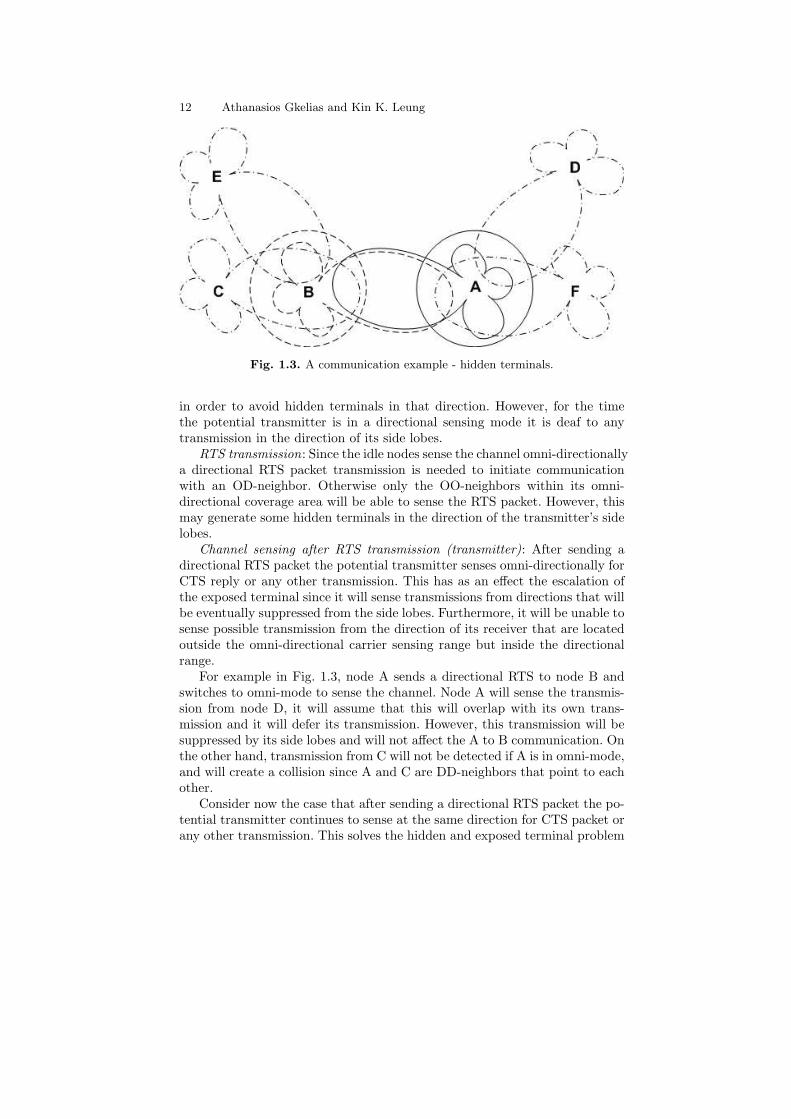
Fig. 1.3. A communication example - hidden terminals.
in order to avoid hidden terminals in that direction. However, for the timethe potential transmitter is in a directional sensing mode it is deaf to anytransmission in the direction of its side lobes.
RTS transmission: Since the idle nodes sense the channel omni-directionallya directional RTS packet transmission is needed to initiate communicationwith an OD-neighbor. Otherwise only the OO-neighbors within its omni-directional coverage area will be able to sense the RTS packet. However, thismay generate some hidden terminals in the direction of the transmitter’s sidelobes.
Channel sensing after RTS transmission (transmitter): After sending adirectional RTS packet the potential transmitter senses omni-directionally forCTS reply or any other transmission. This has as an effect the escalation ofthe exposed terminal since it will sense transmissions from directions that willbe eventually suppressed from the side lobes. Furthermore, it will be unable tosense possible transmission from the direction of its receiver that are locatedoutside the omni-directional carrier sensing range but inside the directionalrange.
For example in Fig. 1.3, node A sends a directional RTS to node B andswitches to omni-mode to sense the channel. Node A will sense the transmis-sion from node D, it will assume that this will overlap with its own trans-mission and it will defer its transmission. However, this transmission will besuppressed by its side lobes and will not affect the A to B communication. Onthe other hand, transmission from C will not be detected if A is in omni-mode,and will create a collision since A and C are DD-neighbors that point to eachother.
Consider now the case that after sending a directional RTS packet the po-tential transmitter continues to sense at the same direction for CTS packet orany other transmission. This solves the hidden and exposed terminal problem

1 Multiple Antenna Techniques for Wireless Mesh Networks 13
Fig. 1.4. Directional CTS communication.
of the previous case but will not avoid hidden terminals from the direction ofits side lobes. For example, the node A becomes deaf to the direction of nodeF. Node F may create interference to node B since they are DD-neighborsthat point to each other.
Channel sensing before CTS transmission (receiver): After a node receivesan RTS packet it has to determine its DoA and if a packet is destined foritself or any other node. If the packet is intended for the given receiver itcan directionally sense the channel towards the estimated DoA for any otherongoing or new transmissions. In this way it reduces the impact of both thehidden terminals problem in the direction of the main beam and the exposedterminals problem from the direction of the side lobes. Collisions can stilloccur as it is demonstrated by the following example:
Node B sends an RTS to node A (Fig. 1.3) that successfully receives thepacket and continues to sense the channel omni-directionally before it replieswith a CTS. Node C is unaware of the RTS transmission and performs direc-tional transmission to the direction of A. Node A, which is unable to sensethe transmission from C, will proceed on CTS transmission and collision willoccur since A and C are DD-neighbors that point to its other. In a separatecase, node D, that is also unaware of the RTS transmission, performs direc-tional transmission to the direction of A. Node A will sense the transmissionfrom D and abort its CTS reply. However, this is a wrong decision since thetransmission from D will be suppressed from A’s side lobes and will not affectthe nodes A and B communication. If directional channel sensing takes placeat node A, these two events will be avoided. However node A is unable tosense the transmission from node F that will create interference to node B.This could have been avoided by omni-directional carrier sensing.
CTS transmission: By sending a directional CTS packet the potential re-ceiver will inform the nodes towards its main-beam direction for the forthcom-ing data transmission. However, this does not solve the future hidden terminalproblem from the directions of its side lobes. These terminals will be unableto hear the CTS transmission and the will assume that the channel is idle.For example in Fig. 1.4, node A sends a directional RTS, and node B replieswith directional CTS. In this way, node D that is willing to transmit towardthe direction of B (and therefore performs directional sensing) will be able tosense the CTS. Note that node D has not sensed the directional RTS from
14 Athanasios Gkelias and Kin K. Leung
A. Node C on the other hand will sense the RTS from A but not the CTSfrom B and it may assume that the RTS was unsuccessful and the channelis free. Omni-directional CTS transmission does not solve the problem eithersince the adjacent nodes sense omni-directionally the channel and thereforeonly the OO-neighbor may sense the CTS transmission (OD-neighbors maybe able to sense the CTS transmission only if they point towards the directionof the CTS transmitter). For example, node D (in Fig. 1.4) will not be ableto sense an omni-directional CTS transmission from B.
Data and acknowledgment transmission: Data transmission and positive ornegative acknowledgment from the receiver have to take place in a directionalway.
Different antenna beamforming patterns: In a practical mesh network it ispossible that not all of the wireless transceiver will be equipped with multipleantennas. Therefore, some of the nodes may be able to perform only omni-directional transmission and reception. Furthermore, the radiation patterns(beam-width and directivity) may be different in each transceiver dependingon the available number of antenna elements. All these issues have to be alsotaken into account in the design of realistic medium access control protocols.
As a conclusion, hidden terminal problem is a highly important and stillopen research issue for nodes communication in a wireless mesh networkthat is complicated by the introduction of directional transmissions. Tradi-tional RTS/CTS techniques are proven to be inadequate for directional trans-missions. Medium access control schemes may have to allocate considerableamount of their wireless resources to mitigate this problem and exploit thebenefits of beamforming. Therefore very careful consideration must be takeninto account in the design of higher layer protocols for wireless mesh networks.
1.4.3 Congestion control: hidden terminal vs deafness fairness
From the above discussion it is clear that packet collision and deafness aretwo different issues that have as a result a node to abort its transmission andincrease its back-off period. However, these two events have to be handled ina different way. For instance, the fact that a receiver is deaf towards a specificdirection does not imply that the network is highly congested; therefore anunsuccessful transmitter should not increase its back-off period because thiswill highly decrease its probability to win the channel contention when thechannel becomes finally available. On the other hand, a series of unsuccessfultransmissions due to collision implies heavy traffic condition that has to behandled by appropriate congestion control.
Therefore, a novel mechanism has to be defined that differentiate thesetwo events and take appropriate action whenever each of them takes place.Moreover most of the existing back-off algorithms have been designed andoptimized for an omni-directional network model. Its performance may haveto be reconsidered for a directional antenna system.

1 Multiple Antenna Techniques for Wireless Mesh Networks 15
1.4.4 Directional NAV
Another issue that has to be taken into account when directional transmissionis employed in a mesh network is the modification of the Network AllocationVector (NAV). Sensing a transmission from a specific direction does not nec-essarily imply that a node has to defer its own transmission and modify itsback-off timer (as it happens in the omni-directional case). On the contrary, ifa node is able to resolve the angle of arrival and deduce that its transmissiondoes not interfere with the ongoing communication, it should presume thatthe channel is idle. Therefore, a node needs a table to keep track of the direc-tions and the corresponding durations towards which a node must not initiatea transmission, i.e., Directional NAV (DNAV). The continuous update of thistable with the right information in order to keep neighbors silenced towardsthe right direction during a transmission is important both for dealing withthe hidden terminal problem as well as for the spatial reuse.
1.4.5 MIMO related issues
Multiple-input multiple-output (MIMO) links have been seen in the previ-ous section to provide high spectral efficiency in rich multi-path environmentsthrough multiple spatial channels without additional bandwidth requirements.This enormous spectral efficiency is obtained for a single link with no exter-nal interference. In a wireless mesh environment though, there will be channelreuse and therefore co-channel interference from other APs transmissions.Recent research results have shown that co-channel interference can seriouslydegrade the overall capacity when MIMO channels are used in a cellular sys-tem [29].
Moreover, it has been proven that for flat Rayleigh fading channels, withindependent fading coefficients for each path, it is possible to achieve highercapacity by reducing the number of MIMO streams. More specifically, for asystem with n receive antennas, m transmit streams and k interfering streams,all the m transmit streams can be isolated and decoded successfully as long asm+k ≤ n. A group of m antenna elements will be used for data reception whilethe remaining n−m elements are used to null out the interfering streams. Thebest performance is achieved when all the degrees of freedom of the MIMOchannel are used, i.e., m = n− k. On the other hand, if the incoming streamsare more than the receiver antenna elements (i.e., m + k ≥ n), it may notbe possible for the receiver to decode any of the desired signal streams if theexcess streams degrade the overall SINR below a threshold. It must be notedhere that if the interfering (k) streams are far weaker than the desired (m)streams, it may be possible to decode the desired streams (even if m+k ≥ n)given that the SINR is above the required threshold.
These observations can be directly applied to the design requirements ofmultiple access schemes for wireless mesh networks with MIMO channels.

16 Athanasios Gkelias and Kin K. Leung
Moreover, it has been shown [20] that for multi-user communication, the chan-nel capacity can be achieved by letting all the users simultaneously transmitand jointly decoded by the receiver rather than organize orthogonal channelaccess. However, the total number of possible simultaneous transmissions thatcan be decoded is limited by the number of the antenna elements at the re-ceiver end. Given n receiver antennas, a rule of thumb is to have groups of nusers transmit simultaneously and schedule different groups in an orthogonalway (e.g., TDMA).
In a wireless mesh network where multiple antennas are deployed at eachAP a transmission can occupy multiple streams depending on the number oftransmit antenna elements. In this case, it is more appropriate if a transmitterchooses only a subset of the strongest streams and distributes its power (e.g.using different water-filling techniques) over these streams instead of usingthe maximum number of streams for transmission [9]. The gain (known asstream control gain) is twofold: only the best channel modes (streams) areused for transmission while on the other hand multiple transmissions takeplace simultaneously which leads closer to capacity achievement as discussedabove. The optimal number of simultaneous transmissions depends on thenumber of antenna elements used in each transceiver subset, the number ofantennas at the receiver end and the number of possible interfering streams.
However, this requires perfect channel state estimation at the transmitterend in order to choose the strongest channel modes. At the receiver side,MMSE is the optimal compromise between maximizing the signal strengthfrom the user of interest and suppressing the interference from the other users.Even better performance can be achieved from an MMSE with successiveinterference cancelation (MMSE-CSI) receiver.
All these make clear the paramount importance for novel medium accesscontrol and routing schemes that exploit these new communication opportu-nities provided by MIMO channels. For instance, the MAC scheduler shouldbe able to allocate appropriate number of streams per transmitter-receiverpair in a way that a receiver is not overwhelmed by extended number oftransmissions. This gives a rise to new kind of hidden and exposed terminalissue. Optimal resource allocation between data and feedback channel mustbe also performed (for instance, this information can be included in RTS andCTS packets [9]) so that always the best channel models are used. Here, afairness model (e.g. proportional fairness) should be used in conjunction withthe medium access control scheme so that weaker links in the mesh networkare not starving. Moreover appropriate power control schemes needed so thatinterference suppression can be performed in the receiver side in conjunctionwith the stream control. The multiplexing vs diversity trade off must be alsotaken into account since channel reliability and delay limitations are as muchimportant as high throughput for QoS constrained applications. Finally QoSrouting schemes should include these MIMO parameters (degrees of freedom,stream quality, and multi-stream interference) in their utility functions duringroute discovery and maintenance.

1 Multiple Antenna Techniques for Wireless Mesh Networks 17
1.4.6 FCC regulations
In this point we would like to briefly discuss another emerging issue regard-ing the maximum allowed transmitting power for directional transmissions ifthe wireless mesh network operates in unlicensed frequency bands. For exam-ple, U.S. Federal Communications Commission (FCC) regulations extendedthe total effective radiated power in unlicensed radio bands from 30dBm forsingle antenna systems, to 36dBm for beamforming systems. Most of the acad-emic works on MAC and routing schemes for mesh networks do not take intoaccount this parameter and they assume much higher directive gain (com-pared to the omni-directional transmission) in order, for example, to decreasethe number of hops in multi-hop transmissions or increase the network con-nectivity. However this is a realistic and highly important issue that must beconsidered in the design of practical wireless mesh networks.
To summarize this section, it is of paramount importance the introductionof novel medium access control and routing schemes that exploit the bene-fits of multiple antenna deployment on the receiver and/or the receiver sideof a wireless mesh network. Without careful consideration in the design ofhigher layers the usage of smart antenna techniques can have negative impacton the overall mesh network performance. This is why recently the designand performance analysis of medium access control and routing schemes withmultiple antennas have attracted high research interest and some of them willbe presented in the next section. A cross-layer approach must be taken sincemost of the issues cannot be handled by individual layers.
1.5 Smart antennas for scheduling
In the following we describe a number of proposed medium access controlschemes with multiple antenna arrays for wireless mesh networks. These pro-tocols are exploiting the benefits of multiple antenna systems while at the sametime are trying to overcome the aforementioned problems and challenges thatmultiple antenna techniques will impose to higher layers. We initially presentsome CSMA based MAC schemes extensions of the popular IEEE 802.11 pro-tocol that take into account the directional transmission property of smartantennas, we follow with description of a TDMA based scheme with direc-tional antennas and we conclude this section with a couple of MAC protocolsthat exploit the diversity and multiplexing gain of MIMO systems.
1.5.1 Directional-MAC (DMAC)
Directional-MAC (DMAC) [30] is a scheme similar to IEEE 802.11 adaptedto the use of directional antennas. The popular 4-way handshake CSMA/CAis used for channel reservation, data transmission and acknowledgment (for

18 Athanasios Gkelias and Kin K. Leung
more information on the 4-way handshake CSMA/CA and IEEE 802.11 pro-tocol see [27]). The RTS and CTS packets are transmitted directionally whilethe idle transceivers listen to the channel omni-directionally. In this way apotential receiver is able to estimate the DoA of the RTS packet and setthe direction of the CTS accordingly. More specifically, the DMAC schemeoperates as follows:
RTS transmission: Under the assumption that a transmitter knows thelocation of the receiver, a source performs directional physical carrier sens-ing towards the direction of the receiver. If the channel is sensed idle thesource checks the back-off counter in the Directional Network Allocation Vec-tor (DNAV) where the virtual carrier sensing status for each DoA is main-tained. If the back-off counter counts down to zero, the RTS packet is direc-tionally transmitted.
RTS reception and CTS reply : An idle transceiver is sensing the channelomni-directionally. In this way, the receiver of an RTS packet should be ableto determine the DoA of the incoming signal (different DoA estimation tech-niques such as ESPRIT [13] and MUSIC [14] can be used). If transmissionis permitted (both directional physical and virtual carrier sensing) towardsthe direction of source, the receiver beamforms towards the direction of thesource and continues to sense the channel for SIFS time slots. If the channelremains free for the duration of SIFS the receiver replies with a CTS packet,otherwise, if the carrier is sensed busy the CTS transmission is canceled (sim-ilar to 802.11 [27]). All the other nodes (except the potential receiver) thatare receiving the RTS packet update their respective DNAV tables with thetransfer duration specified in the RTS packet. This prevents them from trans-mission in a certain range towards the reverse direction of the DoA of thereceiving RTS.
CTS reception and DATA/ACK reply : The source node continues to beam-form to the direction of the receiver, waiting for the CTS packet reply. Ifthe CTS packet is successfully received within the CTS-timeout duration theDATA transmission starts. Both transmitter and receiver have their beamshifted towards the direction of each other. Upon the successful completionof DATA transfer the receiver replies with an ACK. If the CTS packet isnot received within the CTS-timeout duration the transmission is canceledand the source reschedules the transmission of RTS according to the updatedpack-off counter. All other nodes that overhear the CTS, DATA and ACKpackets update their respective DNAV tables with the directions specified inthese packets.
DMAC is a simplified approach that manages to exploit (up to certainpoint) the beamforming capabilities of multiple antenna transmitters in awireless mesh network. Nevertheless, DMAC has failed to address the deafnessproblem while hidden terminals still exit as a result of the omni-directionalchannel sensing. Moreover, DMAC is unable to establish direct communica-

1 Multiple Antenna Techniques for Wireless Mesh Networks 19
tion between DD-neighbors. See [24] for a more thorough discussion on theproblems with DMAC.
1.5.2 Multi-hop RTS MAC protocol (MMAC)
Multi-hop RTS MAC (MMAC) protocol [23] is an extension of the basicDMAC protocol described before. MMAC attempts to exploit the extendedtransmission range property of directional antennas. If both transmitter andreceiver are pointing their beams to each other the communication range canbe significantly extended. DMAC has failed to address this property sincethe idle transceivers listens omni-directionally for new transmissions. This ishighly important since it can reduce the number of hops between source anddestination and reduce the end-to-end delay in multi-hop communications andincrease the spatial reuse factor.
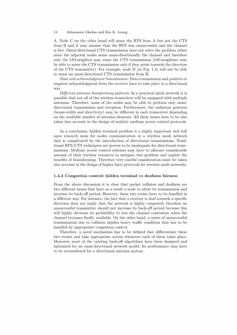
Although two DD-neighbors can communicate with each other directly,they need somehow to coordinate their beams to point to each other’s direc-tion. This is the main motivation of MMAC protocol that attempts to find analternative DO-neighbor route for signaling exchange between the two DD-neighbors to coordinate their directions of transmission. To achieve this, anRTS packet has to be forwarded from the DD-source through multiple DO-neighbors to reach the DD-destination while the DD-source is inactively wait-ing for CTS reply. For instance, in Fig. 1.5, nodes A and B are DD-neighborsthat cannot communicate unless they point each other. An RTS packet issent through the A-C-D-B route to inform B for A’s intention. The multi-hopRTS transmission and CTS, DATA and ACK packet exchange mechanism isdescribed in the following:
RTS transmission: MMAC protocol does not provide any neighbor dis-covery phase. Therefore it is anticipated that each node have knowledge ofthe position of all its DD and DO-neighbors. Moreover it is assumed that amodule running above the MAC layer is capable of deciding the appropri-ate communication scheme (e.g. sometimes it may be more appropriate touse multi-hop DO-route rather than direct DD-transmission) and finding theoptimal DO-route to a DD-neighbor.
The source performs directional physical carrier sensing towards the direc-tion of the potential DD-neighbor receiver. If the channel is sensed idle andalso the DNAV allows a transmission to this direction, the source is sendingan RTS packet towards the DD-receiver. There is a high probability that thispacket may not reach the destination DD-neighbor since this node may be inomni-mode or has shifted its beam to different direction. The aim of such atransmission is to reserve the channel in the region between the DD-neighborsrather than to successfully deliver the RTS packet. Nodes in this region thatoverhear the RTS transmission will update their DNAV table to defer anytransmission towards the directions of both the DD-neighbor nodes for a cer-tain time. This time duration is specified in the RTS packet and is equal to
20 Athanasios Gkelias and Kin K. Leung
Fig. 1.5. DD-link activation in MMAC protocol.
the time required for the RTS packet to reach the DD-receiver plus the CTSpacket transmission time (these time durations are described in the following).
If the DD-receiver happens to be beamformed to the direction of RTS,it may directly reply with a CTS packet and the DD-neighbors can pro-ceed on the DATA/ACK phase. Otherwise, the DD-transmitter constructsa special type of RTS packet (called forwarding RTS) that is delivered todestination over multiple DO-hops. This packet contains the information ofthe DO-neighbors in the route from source to destination. None of the nodesmodify their DNAV tables on receiving or overhearing the forwarding-RTSpacket. The forwarding-RTS packet gets highest priority for transmission (itdoes not involve any back-off) while the nodes in the forwarding route sim-ply drop the RTS if they are busy. This implies that the time required for asuccessful RTS transmission is a constant, known a priori.
RTS reception and CTS reply: In the DD-receiver side two events mayhappen. If this receiver happens to be beamformed to the direction of the DD-transmitter it can receiver the direct RTS packet. In this case it can directlyreply with a directional CTS packet such that the multiple RTS forwardingprocedure will be avoided. (Note that in [23] it is not clear when such anevent may happen, since whenever a node is idle and able to receive it willbe in omni-mode by default. Nevertheless, this can happen in case the DD-neighbor pair wants to extend their ongoing communication). In the secondevent, on receiving the forwarding-RTS packet, the DD-receiver proceeds onvirtual and physical carrier sensing toward the direction of the DD-transmitter

1 Multiple Antenna Techniques for Wireless Mesh Networks 21
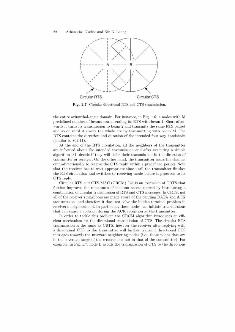
Fig. 1.6. Circular directional RTS transmission.
for SIFS time slots (similar to DMAC) and continues with CTS directionaltransmission.
CTS reception and DATA/ACK reply: Upon the reception of the CTSpacket, the DD-link has been established and the DATA transmission starts.If the DATA transmission finishes successfully, the DD-receiver acknowledgesthe DD-transmitter with an ACK packet. If no CTS packet received duringthe CTS-timeout duration the transmission is aborted and the DD-transmitterreschedules the RTS transmission according to its directional back-off timer.Nodes that overhear the CTS and DATA packets update their DNAV withthe duration specified in the packets.
MMAC can significantly increase the spatial reuse in a wireless mesh net-work. Simulation results for random topologies [24] have been shown thatMMAC outperforms DMAC and IEEE 802.11 with omni-directional trans-missions. The performance of MMAC is expected to be even better in thecase of wireless mesh networks where the topology is more structured andstatic. Nevertheless, the multi-hop forwarding of RTS packet highly increasethe probability of packet collision or drop (since back-off is not used) espe-cially when the traffic demand in the network increases. This can offsets theadvantages of utilizing DD-links when using MMAC as it increases the averageend-to-end delay compare to DMAC.
1.5.3 CRTS and CRCM:
Circular RTS (CRTS) [31] is a simple in implementation protocol based onthe concept of the IEEE 802.11 but it uses only directional transmissions. Itassumes antenna with predefined number if beams i.e., switched beam an-tenna, that cover all the area around the transmitter. In this scheme the RTSis transmitted directional consequently, in a circular way, so that it covers
22 Athanasios Gkelias and Kin K. Leung
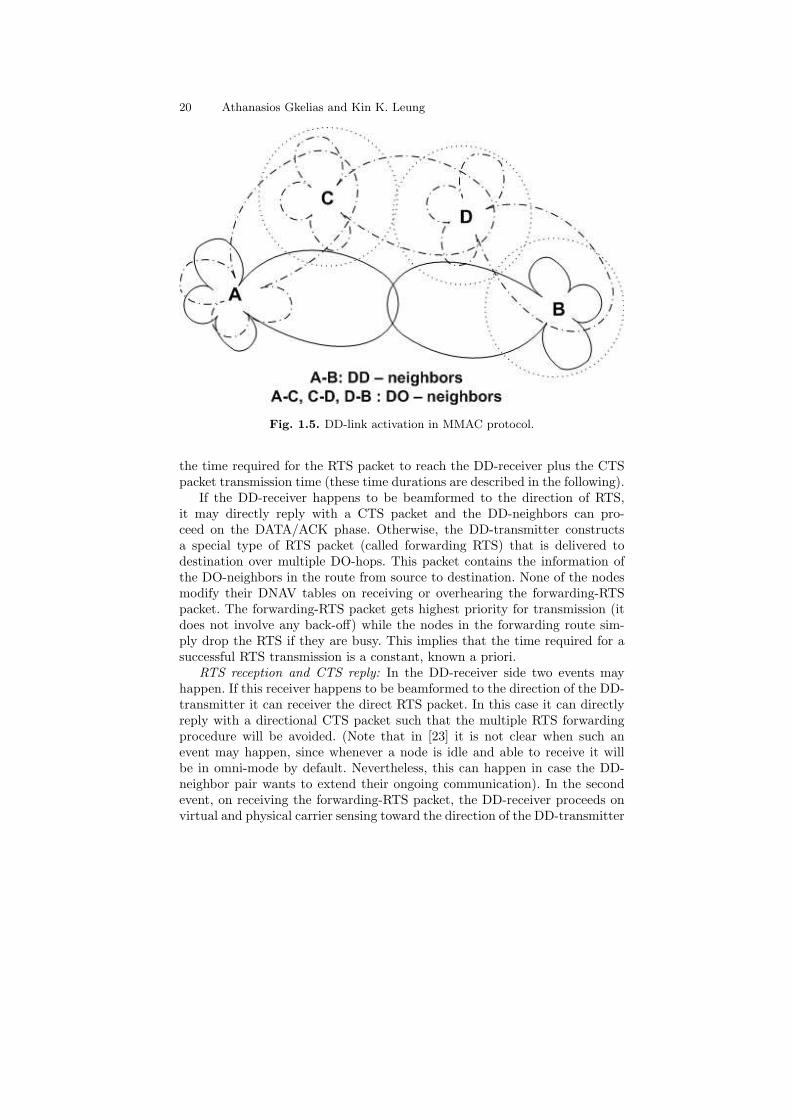
Fig. 1.7. Circular directional RTS and CTS transmission.
the entire azimuthal-angle domain. For instance, in Fig. 1.6, a nodes with Mpredefined number of beams starts sending its RTS with beam 1. Short after-wards it turns its transmission to beam 2 and transmits the same RTS packetand so on until it covers the whole are by transmitting with beam M. TheRTS contains the direction and duration of the intended four way handshake(similar to 802.11).
At the end of the RTS circulation, all the neighbors of the transmitterare informed about the intended transmission and after executing a simplealgorithm [31] decide if they will defer their transmission in the direction oftransmitter or receiver. On the other hand, the transmitter hears the channelomni-directionally to receive the CTS reply within a predefined period. Notethat the receiver has to wait appropriate time until the transmitter finishesthe RTS circulation and switches to receiving mode before it proceeds to itsCTS reply.
Circular RTS and CTS MAC (CRCM) [32] is an extension of CRTS thatfurther improves the robustness of medium access control by introducing acombination of circular transmission of RTS and CTS messages. In CRTS, notall of the receiver’s neighbors are made aware of the pending DATA and ACKtransmissions and therefore it does not solve the hidden terminal problem inreceiver’s neighborhood. In particular, these nodes can initiate transmissionsthat can cause a collision during the ACK reception at the transmitter.
In order to tackle this problem the CRCM algorithm introduces an effi-cient mechanism for the directional transmission of CTS. The circular RTStransmission is the same as CRTS, however the receiver after replying witha directional CTS to the transmitter will further transmit directional CTSmessages towards the unaware neighboring nodes (i.e., those nodes that arein the coverage range of the receiver but not in that of the transmitter). Forexample, in Fig. 1.7, node B avoids the transmission of CTS to the directions

1 Multiple Antenna Techniques for Wireless Mesh Networks 23
that have been already covered by the circular RTS message. The receiver’sneighbors execute the same algorithm [32] as did the transmitter’s neighborsin order to decide on whether or not to postpone their transmission towardsthe sender-receiver pair.
CRCM algorithm gives a solution to the hidden terminal problem dueto asymmetry in gain, arising due to the deployment of directional antennasin wireless ad hoc or mesh networks. While power consumption because ofthe extensive circular packet transmission is not an important issue in meshnetworks, the time spent for these transmissions can be proven crucial forseveral delay sensitive applications.
1.5.4 ToneDMCA
ToneDMAC [24] is a medium access control scheme that tries to alleviatethe impact of deafness problem while retaining the benefits of directionalbeamforming. Similar to previous directional MAC protocols, ToneMAC hasadopted the CSMA/CA principles of IEEE 802.11 and combines it withswitched beam antenna transceiver and a tone-based mechanism. The mainidea is that both transmitter and receiver, after the completion of theircommunication, transmit omni-directionally out-of-band tones to differenti-ate deafness from congestion. In this way, the backlogged nodes can deducedeadness as the cause of their previous failure (and not congestion) and adjusttheir back-off interval accordingly.
In the beginning, the transmitter and receiver exchange directional RTSand CTS packets without trying to inform their “omni-directional” neighborsof their intended communication. If the initial handshake is successful, dataand ACK packets transmission follow in a similar directional way. After thecompletion of their dialogue, both nodes omni-directionally transmit out-of-band tones to notify their neighbors that it was them that have been engagedin communication over the recent past.
The intended transmitter beamforms in the direction of its intended re-ceiver and performs physical carrier sensing towards that direction. If thechannel is sensed idle the transmitter randomly chooses the time it will trans-mit within the back-off window interval [0, CWmin]. Then it switches to omni-directional mode and senses the channel while performing the back-off count-ing. If a signal is sensed, it performs azimuthal beam scan to determine itsDoA. If the signal arrives from direction different than the direction of its po-tential receiver continues with the countdown. Otherwise it stops the counteruntil the channel is sensed idle again. Note here that since this node is insensing mode, it may happen to receive a RTS packet that is intended foritself. In this case, it may choose to abort its own transmission and reply witha CTS packet, alleviating the possibility of deafness and deadlock.
In ToneMAC the channel is divided into two sub-channels: a data channelwhere RTS, CTS, data and ACK packets are transmitted and narrow control

24 Athanasios Gkelias and Kin K. Leung
channel where the busy tones are sent. The busy tones do not contain anyinformation (e.g. sinusoids with sufficient spectral separation). These tonescan only be detected (through energy estimation) but the receivers will notbe able to determine the sender of the tones. To solve this issue, ToneMACproposes a simple hash function that allocates tones of different frequenciesand time durations to different nodes according to node’s identifier. If a nodei can choose a tone of frequency fi from a set of K frequencies, and an integertime duration ti from an interval [tmin, T ], a simple hash function is used toassign a tuple (fi, ti) to node i such that:
fi = (i mod K) + 1 (1.1)ti = (i mod (T − 1)) + 2. (1.2)
The transmit power of the tones is increased such that the omni-directedtransmission range will be equal to the range of directional transmission.(Please note that even this is what is mentioned in [24], smaller transmis-sion power will be appropriate since the busy-tone has only to be sensed butnot decoded [12]). Of course there is a small probability that two or morenodes have the same (f, t) signature or they may have the same frequencyand different tone duration but their tones overlap in time. This probabilityis quite small since these nodes may be located far away from each otheror they point in different directions; also their randomized back-off countersfurther reduce the probability of simultaneous tone transmission (for moreinformation on this issue see [24]).
ToneDMAC comprises a practical solution for CSMA based mesh net-works with directional antennas due its ability to reduce channel-idle timeand resolve deafness deadlocks. Nevertheless, since tones are transmitted ona narrow bandwidth channel, and the duration of transmission is short, tonesmay be detected partially, or may not be detected at all. Multi-path effectscan also cause a tone to arrive from a different direction than the known direc-tion of a neighbor. Clearly, both these effects can cause a node to misclassifythe cause of transmission failure.
1.5.5 Directional Transmission and Reception Algorithm (DTRA)
DTRA [33] is a TDMA-based MAC algorithm for load-dependent slot reser-vation in a wireless ad hoc network with directional antennas. The maincharacteristics of DTRA are that (1) it provides fully directional transmis-sion/reception, (2) it is distributed, (3) it provides dynamic on-demand slotallocation and reservation to different links and (4) it includes power con-trol. Its TDMA-based reservation scheme makes it appropriate for quality-of-service (QoS) support in wireless ad hoc and mesh networks. DTRA requiresthat each node is equipped with one transceiver with a steerable antenna and

1 Multiple Antenna Techniques for Wireless Mesh Networks 25
all nodes are synchronized. Each node can rapidly switch between transmit-ting and receiving mode (half duplex). In order to communicate, two nodesmust point their beams at each other at the same time and be in a com-plementary transmit-receive mode. The timeline is divided into frames thateach of them comprises three sections dedicated to neighbor discovery, datareservation and data transmission.
Neighbor discovery phase: During neighbor discovery phase a node per-forms a scan by transmitting a sequence of advertisements in each possibledirection. A three-way handshake is used, where the receiver node of an ad-vertisement replying with its own advertisement and expecting to receive anacknowledgment in return within a short time interval. During the three-wayhandshake the nodes can exchange transmit power level information and alsoredefine their directional information. Moreover, they make an agreement onthe future mini-slots that they will listen to each other in the reservationphase (a detailed description of the handshake algorithm and information ex-changed is given in [33]). These agreements are valid until the time the twonodes detect each other again. The actual number of scans needed by a nodeto discover all of its potential neighbors depends on the characteristics of theachievable network graph, its beam-width and the algorithm used in eachnode for their mode (scanning or listening) decision. A deterministic modeselection algorithm is proposed that two neighbors can be detected by eachother in at most log2N scans, where N is the maximum number of nodesin the network. A random mode selection algorithm has been also proposedin [34] where a node decides whether to be in scan or listen mode with equalprobability independent of the decisions made in previous slots.
Slot contention and reservation phase: In the reservation phase, reassur-ance of two nodes connection and reservation of data slots will take place.Two nodes will re-detect each other at the predefined mini-slots by pointingin the direction agreed on during neighbor discovery. A three-way handshakewill take place similar to the discovery phase where the two nodes negotiatewho is going to transmit/receive and agree on the mutual available slots tobe reserved for data transmission in the next phase. It is possible that noneof the nodes desire to make a reservation or the mutual available slots are notsufficient for their communication (e.g. QoS requirement are not satisfied).
Data transmission and QoS: In order to provide QoS support, three pri-ority queues for each neighbor are defined and the available slots in the datatransmission phase are ranked with a priority metric. When making a reser-vation, if there are not sufficient slot for high-priority traffic, slots allocated tolower priority can be asked to be reallocated. To ensure fairness, a thresholdon the maximum number of slots for each priority class should be set.
One of the main advantages of DTRA protocol is that it takes advantageof the fully directional communication (both directional transmission and re-ception all the time) capability of a multiple antenna system. Moreover itsslot reservation scheme makes it appropriate to a mesh network with vari-

26 Athanasios Gkelias and Kin K. Leung
ous QoS constrains and demands. One of the main disadvantages is its delayperformance for low traffic (e.g., compared to omni-directional IEEE 802.11)because of the fixed resource allocation phase. Such delays will be accumu-lated in each hop in a multi-hop scenario. Since it is based on directionaltransmission, the performance of DTRA will highly degrade in multi-pathcommunication environment without a dominant LOS component.
1.5.6 SD-MAC
SD-MAC [35] is an IEEE 802.11 based medium access control scheme thatexploits the spatial diversity gain of MIMO systems, given that the wirelesstransceiver are employed with multiple antennas. In order to achieve full-order spatial diversity space time coding is used on the transmitter end. CSIknowledge is required at the transmitter while channel gains at the receiverare obtained by using preamble symbols. SD-MAC is based on the RTS/CTSmechanism of the IEEE 802.11 distributed coordination function (DCF). Morespecifically a source node performs channel virtual carrier sensing similar to802.11 and physical carrier sensing by using all its antenna elements. If NAVis empty and channel is sensed free the RTS packet is transmitted in a defaultrate using space-time coding in order to exploit the transmission diversity.The destination node receives the RTS and uses the preamble symbols toperform channel estimation before it decodes the space-time encoded packet.Other nodes that overhear the RTS packet they just decode the transmissionduration and update their NAV tables. The destination node replies with aspace-time encoded CTS packet that contains the rate control information forthe following DATA packet based on the channel estimation. The source nodereceives the CTS packet, adapts its transmission data rate according to theinformation passed by the CTS and transmits the multi-rate DATA packet.The destination replies with a default-rate ACK packet to confirm the datareception.
While SD-MAC scheme exploits the spatial diversity of the MIMO sys-tem, it fails to exploit multiplexing gain. This could be achievable since theRTS/CTS packets can be used as a feedback channel for CSI information atthe transmitter. The diversity can improve significantly the channel reliabilityand increase the transmission rate indirectly. On the other hand, diversity canalso increase the transmission range for the same data rate. This can have agreat impact on the routing scheme since it can reduce the number of hopsand decrease the corresponding end-to-end delay. However, a higher transmis-sion range will increase the area of coverage which can lead to delays due tocontention and packet collisions. The impact of SD-MAC on the routing interms of the optimal hop distance is analyzed in [35].
1 Multiple Antenna Techniques for Wireless Mesh Networks 27
1.5.7 Stream Controlled Medium Access (SCMA)
Both a centralized and distributed versions of Stream Controlled MediumAccess have been proposed in [9]. Since the main focus of this chapter ison distributed algorithms for mesh networks, only the latter version will bepresented here. The main objective of SCMA is to maximize the networkutilization subject to a given fairness model. More specifically SCMA triesto leverage the benefits of stream control (transmission on a subset of thestrongest streams) and partial interference suppression (use the remainingstreams for interference suppression) in a distributed way where all the avail-able degrees of freedom are shared between the mesh network transceivers.The main components of the SCMA algorithm are presented in the following:
Node Coloring: Initially the distributed SCMA protocol performs identi-fication of bottleneck links, i.e., the links that belong to multiple contentionregions in the network. These bottleneck links are colored “red” while the re-maining nodes of each contention region are colored “white”. The red links arescheduled in a non-stream controlled manner (operate on all available steams)while the white links are based on pure stream control. This is due to the factthat the red links are consuming resources from multiple contention regionsthat otherwise can operate simultaneously on all their available resources.Therefore it is preferable that the red links are scheduled independently (forsome examples on how this differentiation will improve the overall resourceallocation together with the complete coloring algorithm description see [9]).
Contention and Channel Access: After the nodes have chosen their color,they move to the channel contention phase that depends on their color.This includes four modes (1) No Contend,(2) Contend,(3) Acquire and (4)Sched White Links. Every node is initially in the No Contend mode. When-ever a node having a packet to transmit it moves to Contend mode withprobability Pnew = Pold (Pold is a network parameter that represents the per-sistence value; the entire network adaptation progress is based on this value).In Contend mode a node chooses a waiting time (in number of slots) uni-formly distributed from the interval (0, B) after which it senses if the channelis busy. The busy state of the channel here corresponds to a lack of availabledegrees of freedom (streams) in the channel around the transmitter and thereceiver. If the channel is sensed busy, the node aborts its transmission andreadjust its persistence to Pold = (1 − β)Pold. Moreover, if the it is a whitenode, it further updates its Pnew value to Pnew = (PoldKold)/Knew. Samereadjustment is performed if the node faces or detects a collision.
If the channel is sensed idle the node proceeds to Acquire mode wherethe actual data transmission takes place. Every node in the two-hop rangeaway from the transmitter automatically expends the appropriate number ofresources (antenna elements) to suppress the interference from this transmis-sion. At the end of a transmission all the neighbour nodes having a packetto transmit increase their persistence Pold = Pold + α, while the white nodesfurther update their Pnew = (PoldKold)/Knew. Typical values for α and β are

28 Athanasios Gkelias and Kin K. Leung
0.1 and 0.5 respectively [9]. In order to determine the resource availability anode has to estimate each time the amount of remaining streams of every nodein its two hop neighbourhood by listening to the control (RTS/CTS) packetstransmissions. Therefore the reception range of the control packets has to beextended by a factor of two. This can be achieved by transmitting multiplecopies of the control packets on at least four streams (double range can beachieved with 4 antenna elements and a path-loss exponent of 4). Since CSI isnot available at the receiver in this stage, space-time block codes can be usedto exploit the transmit diversity gain of MIMO for range extension.
Coordinated Scheduling: The first white node in a clique that gains accessto the channel, it also coordinates the other white nodes to transmit in thesame slot using their own estimated fair share. This is the Sched White Linksmode. This is achieved by the introduction of a flag in the RTS/CTS pack-ets. All the white links that have a packet to transmit schedule themselvesin the same slot, irrespective of whether they contend for channel access inthat slot or not. However, all the transmitting white links (except the initiatorof the coordinating scheduling) will still have to update their persistence toPold = (1− β)Pold.
SCMA algorithm comprises a novel technique to exploit the propitiouscharacteristics of MIMO links in wireless mesh networks. SCMA can im-prove the aggregate network throughput and improve the fairness [9] com-pare to CSMA/CA(k), i.e. conventional CSMA with transmission over all thek-streams. However, as the number the nodes density increases, more indepen-dent contention regions will overlap, and as a result more nodes will be col-ored red and the SCMA network performance will converge to CSMA/CA(k).Moreover, further investigation needed on how the power of adjusted interfer-ing streams does affect the ongoing data stream transmissions.
1.5.8 Conclusions on Scheduling with Multiple Antennas
In this section several distributed medium access control protocols with multi-ple antennas deployment have been presented and their advantages and draw-backs have been discussed. The majority of these schemes ([30][23][31][32][24])are extensions of the popular IEEE 802.11 protocol, therefore are based onrandom channel access that makes them inappropriate for strict QoS con-straints. DTRA [33] protocol provides slot reservation that can promise QoSat the price of relatively high delays for low traffic networks as discussed be-fore. All these protocols are based on beamforming techniques. SD-MAC [35]and SCMA [9] on the other hand, are exploiting the diversity and multiplexinggain respectively of the MIMO channel in order to increase channel reliabilityand data throughput.
The overall mesh network system performance can be further improvedif opportunistic transmissions are considered. Recent work on opportunisticscheduling [36] with omnidirectional transmissions has shown that by using
1 Multiple Antenna Techniques for Wireless Mesh Networks 29
appropriate utility functions considerable opportunistic gain can be achieved,while at the same time the generated interference is reasonably temporal-correlated. This is an important property that ensures satisfactory channelprediction for better distributed power control and scheduling performance.Opportunistic scheduling schemes combined with the aforementioned multipleantenna techniques is an unexplored and promising area of high research inter-est and potentials (e.g., it is part of the research agenda for the MEMBRANEproject [3]).
1.6 Smart antennas for routing
While multiple antenna techniques have been widely analyzed from a MACperspective, their usage and impact on network layer and more specificallytheir interaction with routing has not received much research attention. More-over, the research community interest over the last decades regarding wirelessrouting has been only concentrated on omnidirectional transmissions. In thefollowing we briefly demonstrate and discus a number of proposed routingschemes that take into account multiple antenna techniques (mainly for di-rectional transmission).
The impact of smart antennas on QoS routing for multi-hop wireless net-works is evaluated by simulations in [37] as an extension of the Wireless FixedRelay routing (WiFR) [38] protocol. However, the analysis is based on a math-ematical programming model, and no routing algorithm is defined in terms ofsignaling that has to be exchanged through the route and the required crosslayer interaction in order to solve the aforementioned problems related withdirectional transmissions.
The routing improvement using directional antennas in adhoc networks isdemonstrated in [39] where two techniques are proposed to a) bridge perma-nent network partitions and b) repair routes in use in case of link breakageby using directional transmissions. The design and evaluation is based on theDynamic Source Routing protocol [40], an on-demand routing protocol formobile adhoc networks, in which the originator of a packet decides the entiresequence of hops through which the packet is to be forwarded to the finaldestination. However, this protocol is designed to enhance network connectiv-ity rather than increasing the end-to-end throughput or guarantee quality ofservice. Therefore, the directionality is used only when two nodes are locatedfar enough for omnidirectional communication (the decision is based on SINRmeasurements).
Another approach on routing with beamforming is illustrated in [41]. Theproposed algorithm is based on the well known Ad-Hoc On-Demand DistanceVector routing protocol (AODV) [42] with directional transmitters and omni-directional receivers. Nodes are assumed to be equipped with switched beamantennas consisting of K directional non-overlapping beams each of themspanning an angle of 2π/K radians. For unicasting packets, if the destination

30 Athanasios Gkelias and Kin K. Leung
nodes are located on the direction of the same beam the transmissions aretime multiplexed, while different beams are simultaneously activated if thereceivers are located in separate directions. For broadcasting messages, suchas Route Request, all the beams are activated. However, this work also fails toaddress the problem of deafness and the beam synchronization for DD-nodescommunication.
While the previous work on routing with multiple antennas is mainly fo-cused on using the directionality to increase connectivity, a wireless meshnetwork must also provide high data throughput and meet the various QoSrequirements of the overlying applications. Smart antennas is definitely a keytechnology that can highly contribute towards this direction. Therefore, it is ofparamount importance to design efficient QoS routing protocols that harmon-ically coexist with lower layers and exploit the multiple capabilities and ben-efits that the multiple antenna technologies can provide. For instance, novelrouting schemes exploiting the SDMA opportunities of MIMO techniques haveto be investigated in conjunction with new utility functions comprising of newinterference patterns and increased transmission ranges. Furthermore, algo-rithms for DD-synchronization and communication through the route have tobe designed to reduce end-to-end packet delays.
Conclusions
The impact of multiple antenna array techniques on medium access controlschemes for mesh networks has been analyzed in this chapter. Several multi-ple antenna architectures and methodologies, such as steered-beam antennas,adaptive antennas and MIMO coding, have been demonstrated. It has beenclear that while these techniques can significantly improve the performanceof single-link communications, from a wireless mesh network perspective theycan also considerably degrade the overall performance of wireless mesh net-works if careful consideration of their interaction with higher layers is nottaken into account. Deferent design challenges, such as deafness, hidden andexposed terminals and MIMO related issues have been discussed. Several pro-posed MAC protocols for wireless ad hoc and mesh networks with directionalantennas and MIMO techniques have been presented and their advantagesand weaknesses have been discussed. Finally, we briefly discussed the lack ofefficient routing algorithms for nodes with multiple antennas and the need ofrouting schemes that exploit the smart antenna’s capabilities.
Acknowledgement
The work presented in this chapter has been performed in the frameworkof the IST-4-027310 MEMBRANE project (partly) funded by the EuropeanCommission 6th Framework Programme.

1 Multiple Antenna Techniques for Wireless Mesh Networks 31
References
1. I. F. Akyldiz, X. Wang, “A Survey on Wireless Mesh Networks,” IEEE Com-munications Magazine, pp. 23-30, vol. 43, issue 9, Sept. 2005.
2. I. F. Akyldiz, X. Wang, W. Wang, “Wireless Mesh Networks: a survey,” ELSE-VIER Computer Networks, pp. 445-487, vol. 47, no. 4, March 2005.
3. IST-MEMBRANE: Multi-Element Multihop Backhaul Reconfigurable AntennaNetwork (www.ist-membrane.org).
4. P. H. Lehne and M. Pettersen, “An Overview of Smart Antenna Technology forMobile Communication Systems,” IEEE Communications Surveys, pp. 2-13,Vol. 2, No. 4, Fourth Quarter 1999.
5. A. Alexiou, M. Haardt, “Smart Antenna Technologies for Future Wireless Sys-tems: Trends and Challenges,” IEEE Communications Magazine, pp. 90-97,Sept. 2004.
6. M. Webb, M. Beach, A. Nix, “Capacity Limits of MIMO Channels with Co-Channel Interference,” in Proc. of VTC 2004-Spring, 17-19 May 2004.
7. Y. Song and S. D. Blostein, “MIMO Channel Capacity in Co-Channel Interfer-ence,” in Proc. of 21st Biennial Symposium on Communicatios, pp. 220 - 224,June 2002.
8. S. Bandyopadhyay, S. Roy, T. Ueda, Enhancing the Performance of Ad HocWireless Networks with Smart Antennas, Auerbach Publications, 2006.
9. K. Sundaresan, R. Sivakumar, M.A. Ingram, T.-Y. Chang, “Medium AccessControl in Ad Hoc Networks with MIMO Links: Optimization Considerationsand Algorithms,” IEEE Trans. on Mobile Computing, pp. 350-365, vol. 3, no.4, Oct.-Dec. 2004.
10. J. H. Winters, “Smart Antennas for Wireless Systems,” IEEE Personal Com-munications, pp. 23-27, vol. 5, no. 1, Feb. 1998.
11. J. H. Winters, “Smart Antenna Techniques and Their Application to WirelessAd Hoc Networks,” IEEE Wireless Communications, pp. 77-83, vol. 13, no. 4,Aug. 2006.
12. J. A. Stine, “Exploiting Smart Antennas in Wireless Mesh Network Using Con-tention Access,” IEEE Wireless Communications, pp. 38-49, vol. 13, no. 2, April2006.
13. R. H. Roy, T. Kailath, “ESPRIT - Estimation of Signal Parameters via Rota-tional Invariance Techniques,” IEEE Trans. on Acoustics, Speech, and SignalProcessing, pp. 984 - 995, vol. 37, no. 7, July 1989.
14. R. O. Schmidt, “Multiple emitter location and signal parameter estimation,”IEEE Trans. on Antennas Propagation, pp. 276-280, vol. 34, no. 3, March 1986.
15. S. Bellofiore, J. Foutz, R. Govindaradjula, I. Bahceci, C.A. Balanis, A.S.Spanias, J.M. Capone, T.M. Duman, “Smart antenna system analysis, inte-gration and performance for mobile ad hoc networks (MANETs),” IEEE Trans.on Antennas and Propagation, pp. 571-581, vol. 50, no. 5, May 2002.
16. S.M. Alamouti, “A simple transmit diversity technique for wireless commu-nications,” IEEE Journal on Selected Areas in Communications (JSAC), pp.1451-1458, vol. 16, no. 8, Oct. 1998.
17. V. Tarokh, H. Jafarkhani, and A. R. Calderbank, “Space-time block codes fromorthogonal designs,” IEEE Trans. on Information Theory, pp. 1456-1467, vol.45, no. 5, July 1999.
32 Athanasios Gkelias and Kin K. Leung
18. P. W. Wolniansky, G. J. Foschini, G. D. Golden, R. A. Valenzuela, “V-BLAST:an architecture for realizing very high data rates over the rich-scattering wirelesschannel,” in Proc. of URSI International Symposium on Signals, Systems, andElectronics, Sept.-Oct. 1998.
19. G. J. Foschini, “Layered Space-Time Architecture for Wireless Communicationin a Fading Environment when Using Multi-Element Antennas,” Bell Labs Tech-nical Journal, pp. 41-59, vol. 1, no. 2, Fall 1996.
20. D. Tse and P. Viswanath, Fundamentals of Wireless Communications, Cam-bridge University Press 2005.
21. L. Zheng and D. Tse, “Diversity and Multiplexing: A Fundamental Tradeoff inMultiple-Antenna Channels,” IEEE Trans. on Information Theory, pp. 1073-1096, vol. 49, no. 5, May 2003.
22. K. Sundaresan, S. Lakshmanam, R. Sivakumar, “On the Use of Smart Antennasin Multi-Hop Wireless Networks,” in Proc. of BROADNETS, Oct. 2006.
23. R. R. Choudhury, X. Yang, R. Ramanathan, N. H. Vaidya, ”Using DirectionalAntennas for Medium Access Control in Ad Hoc Networks,” in Proc. of ACMMOBICOM’02, Sept. 2002.
24. R. R. Choudhury and N. H. Vaidya, “Deafness: A MAC Problem in Ad HocNetworks when using Directional Antennas,” in Proc. of the 12th IEEE Inter-national Conference on Network Protocols (ICNP’04), Oct. 2004.
25. F. A. Tobagi and L. Kleinrock, “Packet switching in radio channels: Part II - thehidden terminal problem in carrier sense multiple-access modes and the busy-tone solution,” IEEE Trans. in Communications, pp. 1417-1433, vol. COM-23,no. 12, Dec. 1975.
26. P. Karn, “MACA - A New Channel Access Method for Radio Packet Radio,”in Proc. of the 9th ARRL Computer Networking Conference, 1990.
27. ANSI/IEEE Std 802.11, “Wireless LAN Medium Access Control (MAC) andPhysical Layers (PHY) Specifications,” 1999.
28. G. Li, L. L. Yang, W. S. Conner, B. Sadeghi, “Opportunities and Challenges forMesh Networks Using Directional Antennas,” in Proc. of IEEE WiMesh, Sept.2005.
29. M. F. Damirkol, M. A. Ingram, “Stream Control in Networks with InterferingMIMO Links,” in Proc. of Wireless Communications and Networking WCNC,March 2003.
30. Y. B. Ko, V. Shankarkumar and N. H. Vaidya, “Medium Access Control Pro-tocols Using Directional Antennas in Ad Hoc Networks,” in Proc. of IEEEINFOCOM, March 2000.
31. T. Korakis, G. Jakllari, L. Tassiulas, “A MAC Protocol for Full Exploitation ofDirectional Antennas in Ad-Hoc Wireless Networks,” in Proc. of ACM MobiHoc,June 2003.
32. G. Jakllari, I. Broustis, T. Korakis, S. V. Krishnamurthy, L. Tassiulas, “Han-dling Asymmetry in Gain in Directional Antenna Equipped Ad Hoc Networks,”in Proc. of IEEE PIMRC, Sept. 2005.
33. Z. Zhang, “DTRA: Directional Transmission and Reception Algorithms inWLANs with Directional Antennas for QoS Support,” IEEE Network, pp. 27-32,vol. 19, no. 3, May-June 2005.
34. M. E. Steenstrup, “Neighbor Discovery Among Mobile Nodes Equipped withSmart Antennas,” in Proc. of ADHOC’03, May 2003.
1 Multiple Antenna Techniques for Wireless Mesh Networks 33
35. M. Hu and J. Zhang, “MIMO Ad Hoc Networks: Medium Access Control, Satu-ration Throughput and Optimal Hop Distance,” Special Issue on Mobile Ad HocNetworks, Journal of Communications and Networks, pp. 317-330, Dec. 2004.
36. Yun Hou and Kin K. Leung, “A Novel Distributed Scheduling Algorithm forWireless Mesh Networks,” in Proc. of IEEE Globecom 2007, Nov. 2007.
37. L. Coletti, D. Ciglioni, A. Capone, M. Zambardi, “Impact of Smart Antennas onQoS Routing for Muli-hop Wireless Networks,” in Proc. of the 14th IST Mobileand Wireless Communications Summit, June 2005.
38. A. Capone, L. Coletti, M. Zambardi, “QoS Routing in Multihop Wireless Net-works: New Model and Algorithm,” in Proc. of QoS-IP 2005, Feb. 2005.
39. A. K. Saha, D. B. Johnson, “Routing Improvement Using Directional Antennasin Mobile Ad Hoc Netwroks,” in Proc. of IEEE Globecom 2004, Nov. 2004.
40. D. B. Johnson, D. A. Maltz, “Dynamic Source Routing in Ad Hoc WirelessNetworks,” Mobile Computing, ch. 5, pp. 153-181, Kluwer Academic Publishers,1996.
41. N. Nie, C. Comaniciu, “Energy Efficient AODV Routing in CDMA Ad Hoc New-torks Using Beamforming,” in Proc. of IEEE Vehicular Technology Conference(VTC), May-June 2005.
42. C. E. Perkins, “Ad hoc On-Demand Distance Vector (AODV) Routing,” RFC3561, IETF Network Working Group, July 1998.