1 Magnetic proximity switches Series CST - CSV and CSH
11
The company reserves the right to vary models and dimensions without notice. Products designed for industrial applications. Sale to general public is forbidden. MOVEMENT > Proximity switches Series CST-CSV-CSH CATALOGUE > Release 8.2 1 01 1/9.05 Magnetic proximity switches Series CST - CSV and CSH Reed, Hall effect and magnet-resistive The magnetic proximity switches CST-CSV-CSH detect the position of the cylinder piston. When the internal contact is actuated by a magnetic field, the sensors complete an electrical circuit and provide an output signal to directly actuate a solenoid valve or a PLC. A yellow LED diode shows when the internal magnetic contact is closed. Switches are available in three different versions: Reed with mechanical switching, Hall effect and magnet-resistive with electronic switching. Hall effect and magnet-resistive versions are suggested for heavy duty with frequent operations and strong vibrations. GENERAL DATA Designed to fit into the cylinder profile barrel 3 models (CST - CSV - CSH) are suitable for all Camozzi’s cylinder range With or without M8 connector » » » Models CST-... CSV-... CSH-... Operation Reed contact Hall effect (CST and CSV ) Magnet-resistive ( CSH ) Output Static or electronic PNP Type of contact All switches have Normally Open contact Voltage See model characteristics Max current See model characteristics Max load Reed contact 8 W DC and 10 VA AC Hall effect and magnet-resistive 6 W DC Protection level IP 67 Materials Plastic body encapsulating epoxy resin cable PVC, connector PVC connector body PUR Mounting Directly into the groove, or by means of adapters. Signalling By means of yellow diode Led Protections See model characteristics Switching time Reed contact <1,8 ms Hall effect and Magnet-resistive <1 ms Operating temperature -10 ºC ÷ 80 ºC Electrical duration Reed contact 10.000.000 cycles Hall effect and Magnet-resistive 10.000.000.000 cycles Electrical connection cable 2x0,14 (2m) high flexibility cable 3x0,14 (2m) high flexibility connector M8 and cable 0,3 m
Transcript of 1 Magnetic proximity switches Series CST - CSV and CSH
The company reserves the right to vary models and dimensions without notice. Products designed for industrial applications. Sale to general public is forbidden.
MOVEMENT > Proximity switches Series CST-CSV-CSHCATALOGUE > Release 8.2
1
011/9.05
Magnetic proximity switchesSeries CST - CSV and CSH
Reed, Hall effect and magnet-resistive
The magnetic proximity switches CST-CSV-CSH detect the position of the cylinder piston. When the internal contact is actuated by a magnetic field, the sensors complete an electrical circuit and provide an output signal to directly actuate a solenoid valve or a PLC. A yellow LED diode shows when the internal magnetic contact is closed.
Switches are available in three different versions: Reed with mechanical switching, Hall effect and magnet-resistive with electronic switching.Hall effect and magnet-resistive versions are suggested for heavy duty with frequent operations and strong vibrations.
GENERAL DATA
Designed to fit into the cylinder profile barrel
3 models (CST - CSV - CSH) are suitable for all Camozzi’s cylinder range
With or without M8 connector
»
»
»
Models CST-...CSV-...CSH-...
Operation Reed contactHall effect (CST and CSV )Magnet-resistive ( CSH )
Output Static or electronic PNPType of contact All switches have Normally Open contactVoltage See model characteristicsMax current See model characteristicsMax load Reed contact 8 W DC and 10 VA AC
Hall effect and magnet-resistive 6 W DC Protection level IP 67Materials Plastic body encapsulating epoxy resin
cable PVC, connector PVCconnector body PUR
Mounting Directly into the groove, or by means of adapters.Signalling By means of yellow diode LedProtections See model characteristicsSwitching time Reed contact <1,8 ms
Hall effect and Magnet-resistive <1 msOperating temperature -10 ºC ÷ 80 ºCElectrical duration Reed contact 10.000.000 cycles
Hall effect and Magnet-resistive 10.000.000.000 cyclesElectrical connection cable 2x0,14 (2m) high flexibility
cable 3x0,14 (2m) high flexibilityconnector M8 and cable 0,3 m
The company reserves the right to vary models and dimensions without notice. Products designed for industrial applications. Sale to general public is forbidden.
MO
VEM
ENT
CATALOGUE > Release 8.2MOVEMENT > Proximity switches Series CST-CSV-CSH
02
1
1/9.05
6512 SWITCHES ELECTRICAL CONNECTIONS
Reed switchesBN = brownBU = blueBK = black
Hall effect switchesBN = brownBU = blueBK = black
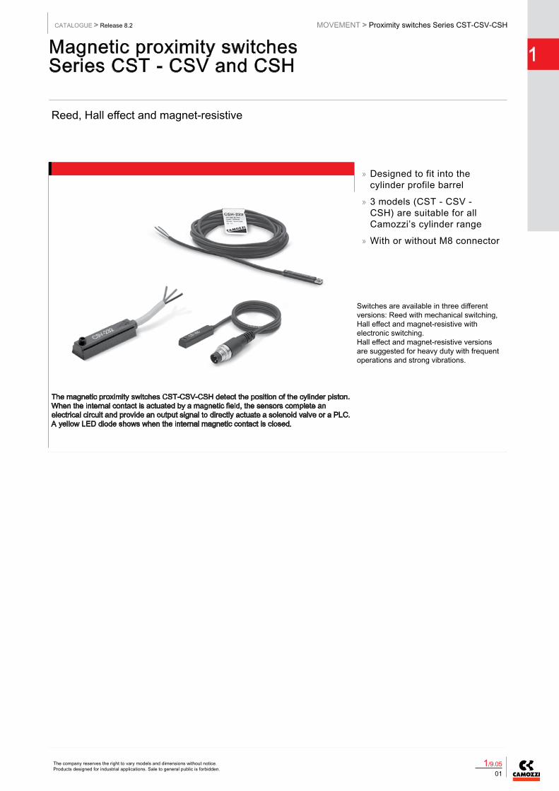
CODING EXAMPLE
CS T - 2 2 0 N - 5
CS SERIES
T SLOT TYPET = T-slotV = V-slotH = frontal inserting slot
2 OPERATION2 = reed3 = electronic
2 CONNECTIONS2 = 2 wires (Reed only )3 = 3 wires5 = 2 wires with M8 connector (Reed only )6 = 3 wires with M8 connector
0 0 = 10-110V DC; 10-230V AC (PNP)1 = 30-110V DC; 30-230V AC (PNP)2 = 3 wires cst (PNP)3 = 10-30V AC/DC (PNP)4 = 10-27V DC (PNP)
N N = ACCORDING TO NORM (CST/CSV-250N only)
5 2 = 2 mt. cable5 = 5 mt. cable
The company reserves the right to vary models and dimensions without notice. Products designed for industrial applications. Sale to general public is forbidden.
MOVEMENT > Proximity switches Series CST-CSV-CSHCATALOGUE > Release 8.2
1
031/9.05
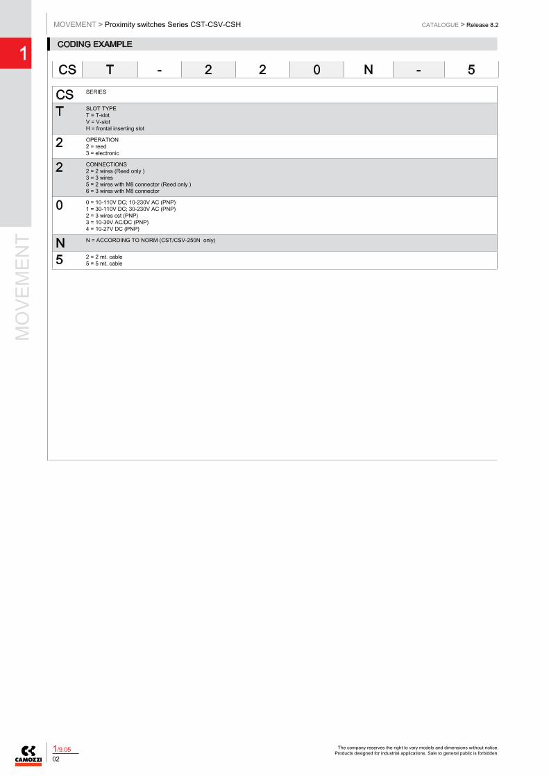
The Reed version with 3 wires allows the connection of severalsensors in series, as there is no voltage drop between the supply and the load (see connecting scheme).The voltage drop is 2,8V for the Reed sensors with 2 wires and 1V for Hall effect sensors with 3 wires.
BN = brownBU = blueBK = blackL = load
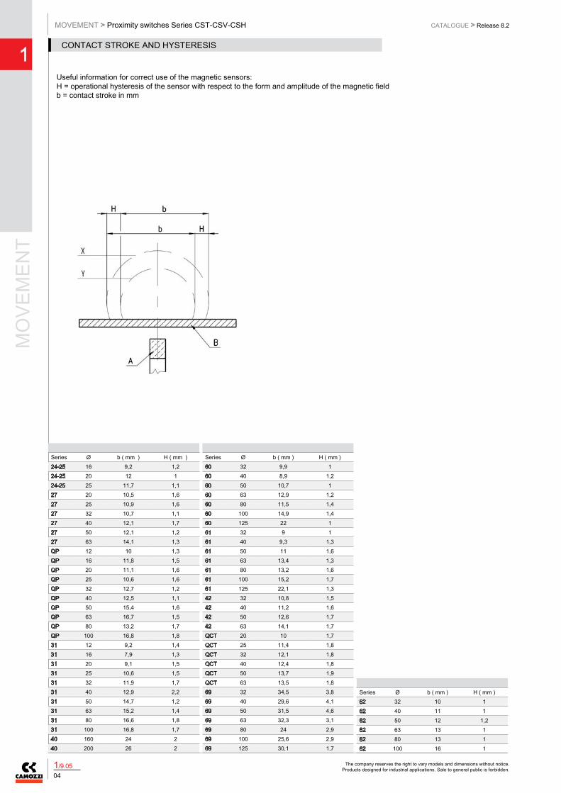
The magnetic sensors consist of a reed switch which is enclosed in a glass bulb containing a rarified gas. The contacts, which are made of magnetic material (nickel-iron), are flexible and are coated, at the contact points with a high quality non-arcing material.Switching is effected by means of a suitable magnetic field and actuation is achieved by means of the permanent magnet inside the piston. The two sensors are of the normally open type and, therefore, when they are subject to the effect of the magnetic field, they close the circuit.The operating field of the sensors with respect to the magnetic piston is shown in this picture. The dimension b indicates the amplitude of the magnetic field or switching field during whichthe circuit is closed. The value H represents the operational hysteresis of the sensor with respect to the form and amplitude of the magnetic field. The operating field, as a result of hysteresis, is displaced by the dimension H in the opposite direction to movement of the piston.The values b and H are shown in the table and are classified according to bore.The maximum speed permitted for each cylinder is a function of the value b and the response time of the various components connected after the sensor.The maximum speed for a cylinder guided by magnetic sensors is calculated as follows: b / t = Speedwhere: b = contact stroke in mm (see table)t = total reaction time in milli seconds of electric control components connected after the sensorSpeed = maximum speed in m/second
Connecting schemes in series
Useful information for correct use of the magnetic sensors
The company reserves the right to vary models and dimensions without notice. Products designed for industrial applications. Sale to general public is forbidden.
MO
VEM
ENT
CATALOGUE > Release 8.2MOVEMENT > Proximity switches Series CST-CSV-CSH
04
1
1/9.05
Useful information for correct use of the magnetic sensors:H = operational hysteresis of the sensor with respect to the form and amplitude of the magnetic fieldb = contact stroke in mm
Series Ø b ( mm ) H ( mm )24-25 16 9,2 1,224-25 20 12 124-25 25 11,7 1,127 20 10,5 1,627 25 10,9 1,627 32 10,7 1,127 40 12,1 1,727 50 12,1 1,227 63 14,1 1,3QP 12 10 1,3QP 16 11,8 1,5QP 20 11,1 1,6QP 25 10,6 1,6QP 32 12,7 1,2QP 40 12,5 1,1QP 50 15,4 1,6QP 63 16,7 1,5QP 80 13,2 1,7QP 100 16,8 1,831 12 9,2 1,431 16 7,9 1,331 20 9,1 1,531 25 10,6 1,531 32 11,9 1,731 40 12,9 2,231 50 14,7 1,231 63 15,2 1,431 80 16,6 1,831 100 16,8 1,740 160 24 240 200 26 2
Series Ø b ( mm ) H ( mm )60 32 9,9 160 40 8,9 1,260 50 10,7 160 63 12,9 1,260 80 11,5 1,460 100 14,9 1,460 125 22 161 32 9 161 40 9,3 1,361 50 11 1,661 63 13,4 1,361 80 13,2 1,661 100 15,2 1,761 125 22,1 1,342 32 10,8 1,542 40 11,2 1,642 50 12,6 1,742 63 14,1 1,7QCT 20 10 1,7QCT 25 11,4 1,8QCT 32 12,1 1,8QCT 40 12,4 1,8QCT 50 13,7 1,9QCT 63 13,5 1,869 32 34,5 3,869 40 29,6 4,169 50 31,5 4,669 63 32,3 3,169 80 24 2,969 100 25,6 2,969 125 30,1 1,7
Series Ø b ( mm ) H ( mm )62 32 10 162 40 11 162 50 12 1,262 63 13 162 80 13 162 100 16 1
CONTACT STROKE AND HYSTERESIS
The company reserves the right to vary models and dimensions without notice. Products designed for industrial applications. Sale to general public is forbidden.
MOVEMENT > Proximity switches Series CST-CSV-CSHCATALOGUE > Release 8.2
1
051/9.05
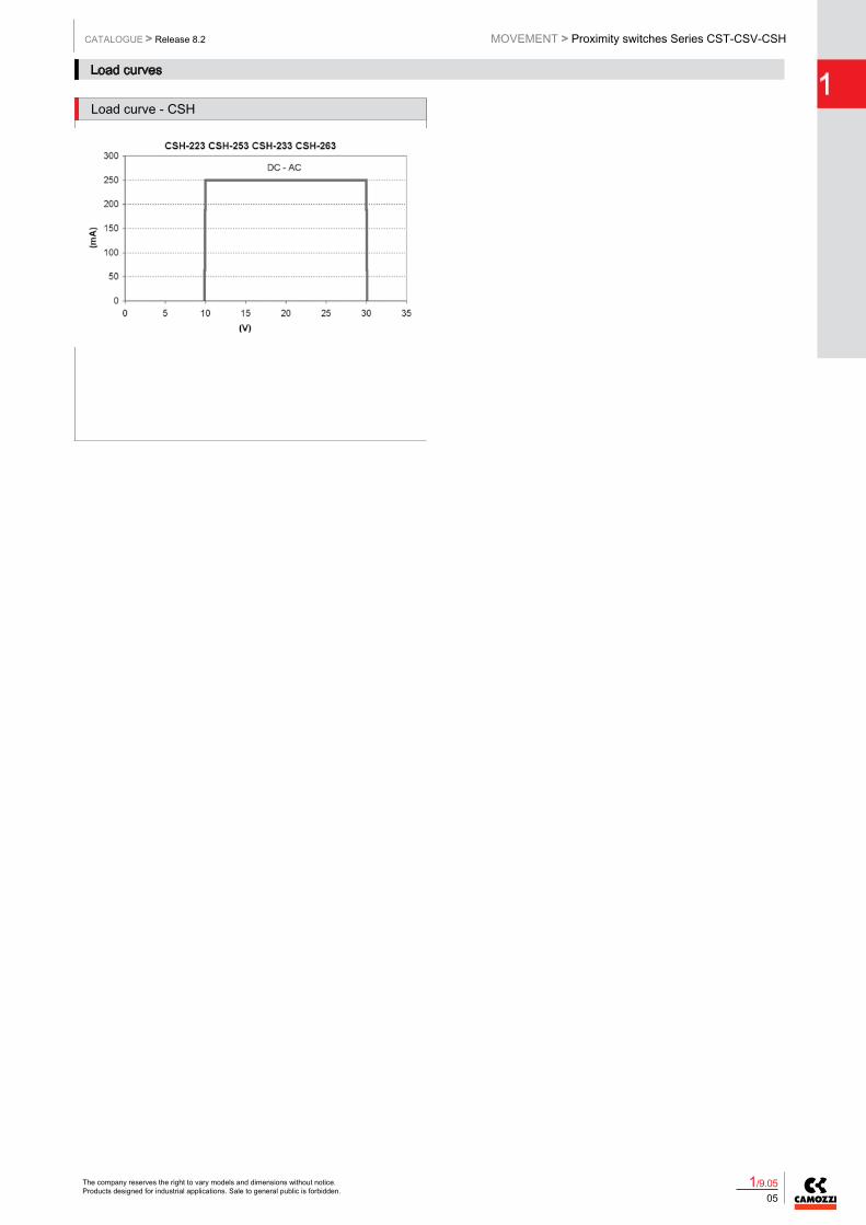
Load curves
Load curve - CSH Load curve - CST/CSV
Load curve - CSH, CST/CSV Load curve - CSH, CST/CSV
Load curve - CSH Load curve - CST/CSV
The company reserves the right to vary models and dimensions without notice. Products designed for industrial applications. Sale to general public is forbidden.
MO
VEM
ENT
CATALOGUE > Release 8.2MOVEMENT > Proximity switches Series CST-CSV-CSH
06
1
1/9.05
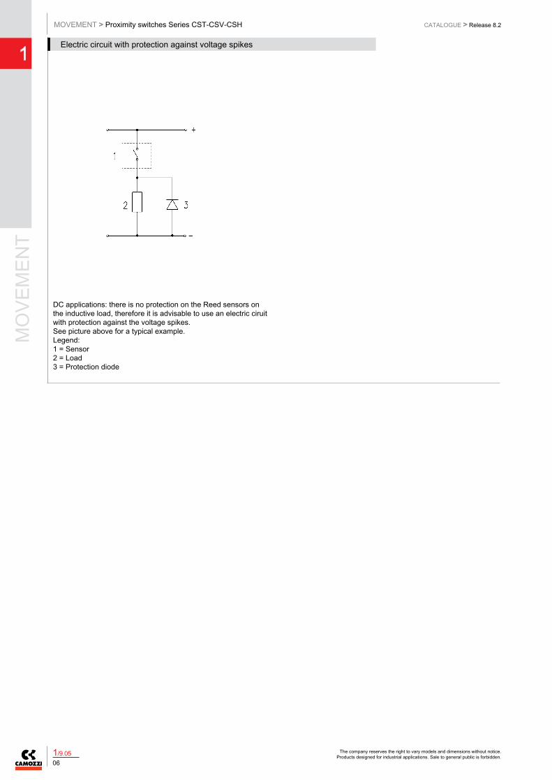
DC applications: there is no protection on the Reed sensors on the inductive load, therefore it is advisable to use an electric ciruit with protection against the voltage spikes.See picture above for a typical example.Legend: 1 = Sensor2 = Load3 = Protection diode
DC and AC applications: there is no protection on the Reed sensors on the inductive load, therefore it is advisable to use an electric ciruit with protection against the voltage spikes.See picture above for a typical example.Legend: 1 = Sensor2 = Load3 = Protection varistor
AC applications: there is no protection on the Reed sensors on the inductive load, therefore it is advisable to use an electric circuit with protection against the voltage spikes.See picture above for a typical example.Legend: 1 = Sensor2 = LoadC + R = Series of resistor and protection capacitor
Electric circuit with protection against voltage spikes
Electric circuit with protection against voltage spikes
The company reserves the right to vary models and dimensions without notice. Products designed for industrial applications. Sale to general public is forbidden.
MOVEMENT > Proximity switches Series CST-CSV-CSHCATALOGUE > Release 8.2
1
071/9.05
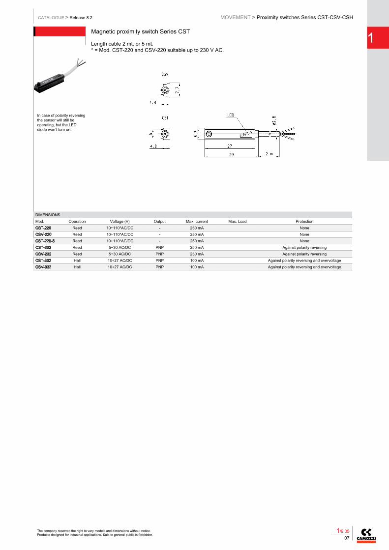
Magnetic proximity switch Series CST
Length cable 2 mt. or 5 mt.* = Mod. CST-220 and CSV-220 suitable up to 230 V AC.
DIMENSIONSMod. Operation Voltage (V) Output Max. current Max. Load ProtectionCST-220 Reed 10÷110*AC/DC - 250 mA NoneCSV-220 Reed 10÷110*AC/DC - 250 mA NoneCST-220-5 Reed 10÷110*AC/DC - 250 mA NoneCST-232 Reed 5÷30 AC/DC PNP 250 mA Against polarity reversingCSV-232 Reed 5÷30 AC/DC PNP 250 mA Against polarity reversingCST-332 Hall 10÷27 AC/DC PNP 100 mA Against polarity reversing and overvoltageCSV-332 Hall 10÷27 AC/DC PNP 100 mA Against polarity reversing and overvoltage
In case of polarity reversing the sensor will still be operating, but the LED diode won’t turn on.
Magnetic proximity switch Series CST with male connector M8
Length cable 0,3 mt.
Mod. Operation Voltage (V) Output Max. current Max. Load ProtectionCST-250N Reed 10÷110* AC/DC - 250 mA NoneCSV-250N Reed 10÷110* AC/DC - 250 mA NoneCST-262 Reed 5÷30 AC/DC PNP 250 mA Against polarity reversingCSV-262 Reed 5÷30 AC/DC PNP 250 mA Against polarity reversingCST-362 Hall 10÷27 DC PNP 100 mA Against polarity reversing and overvoltageCSV-362 Hall 10÷27 DC PNP 100 mA Against polarity reversing and overvoltage
In case of polarity reversing the sensor will still be operating, but the LED diode won’t turn on.
The company reserves the right to vary models and dimensions without notice. Products designed for industrial applications. Sale to general public is forbidden.
MO
VEM
ENT
CATALOGUE > Release 8.2MOVEMENT > Proximity switches Series CST-CSV-CSH
08
1
1/9.05
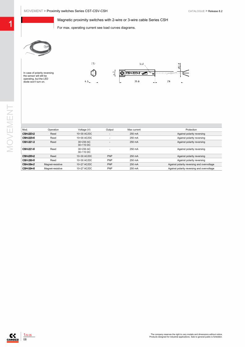
Magnetic proximity switches with 2-wire or 3-wire cable Series CSH
For max. operating current see load curves diagrams.
Mod. Operation Voltage (V) Output Max current ProtectionCSH-223-2 Reed 10÷30 AC/DC - 250 mA Against polarity reversingCSH-223-5 Reed 10÷30 AC/DC - 250 mA Against polarity reversingCSH-221-2 Reed 30÷230 AC
30÷110 DC- 250 mA Against polarity reversing
CSH-221-5 Reed 30÷230 AC30÷110 DC
- 250 mA Against polarity reversing
CSH-233-2 Reed 10÷30 AC/DC PNP 250 mA Against polarity reversingCSH-233-5 Reed 10÷30 AC/DC PNP 250 mA Against polarity reversingCSH-334-2 Magnet-resistive 10÷27 AC/DC PNP 250 mA Against polarity reversing and overvoltageCSH-334-5 Magnet-resistive 10÷27 AC/DC PNP 250 mA Against polarity reversing and overvoltage
In case of polarity reversing the sensor will still be operating, but the LED diode won’t turn on.
Magnetic proximity switches with male connector M8 Series CSH
For max. operating current see load curves diagrams.
Mod. Operation Voltage (V) Output Max current Max Load ProtectionCSH-253 Reed 10÷30 AC/DC - 250 mA Against polarity reversingCSH-263 Reed 10÷30 AC/DC PNP 250 mA Against polarity reversingCSH-364 Magnet-resistive 10÷27 AC/DC PNP 250 mA Against polarity reversing and overvoltage
In case of polarity reversing the sensor will still be operating, but LED diode won’t turn on.
The company reserves the right to vary models and dimensions without notice. Products designed for industrial applications. Sale to general public is forbidden.
MOVEMENT > Proximity switches Series CST-CSV-CSHCATALOGUE > Release 8.2
1
091/9.05
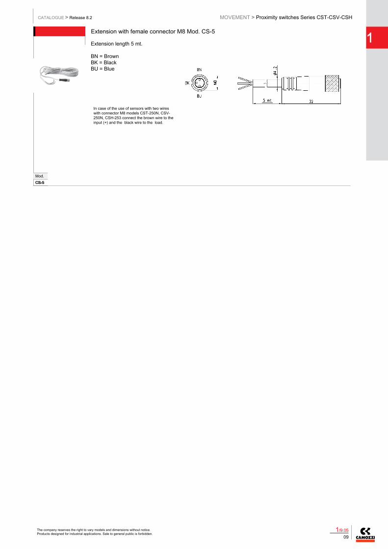
Extension with female connector M8 Mod. CS-5
Extension length 5 mt.
BN = BrownBK = BlackBU = Blue
Mod.CS-5
In case of the use of sensors with two wires with connector M8 models CST-250N, CSV-250N, CSH-253 connect the brown wire to the input (+) and the black wire to the load.
Extension with female/male connector M8 New
Mod. ACS-DW03HB-C250 250CS-DW03HB-C500 500
Mounting brackets for sensors Series CST - CSH
Materials:- from S-CST-05÷12 stainless steel- from S-CST-02÷04 and S-CST-18÷21 technopolymer.
Mod. Cylinder series Ø Mod. Cylinder series Ø Mod. Cylinder series ØS-CST-02 24-25-27 16 S-CST-07 90-92 40 S-CST-12 90 125S-CST-03 24-25-27 20 S-CST-08 90-92 50 S-CST-18 27-42 32S-CST-04 24-25-27 25 S-CST-09 90-92 63 S-CST-19 27-42 40S-CST-05 94-95 16-20-25 S-CST-10 90 80 S-CST-20 27-42 50S-CST-06 90-92 32 S-CST-11 90 100 S-CST-21 27-42 63
The company reserves the right to vary models and dimensions without notice. Products designed for industrial applications. Sale to general public is forbidden.
MO
VEM
ENT
CATALOGUE > Release 8.2MOVEMENT > Proximity switches Series CST-CSV-CSH
10
1
1/9.05
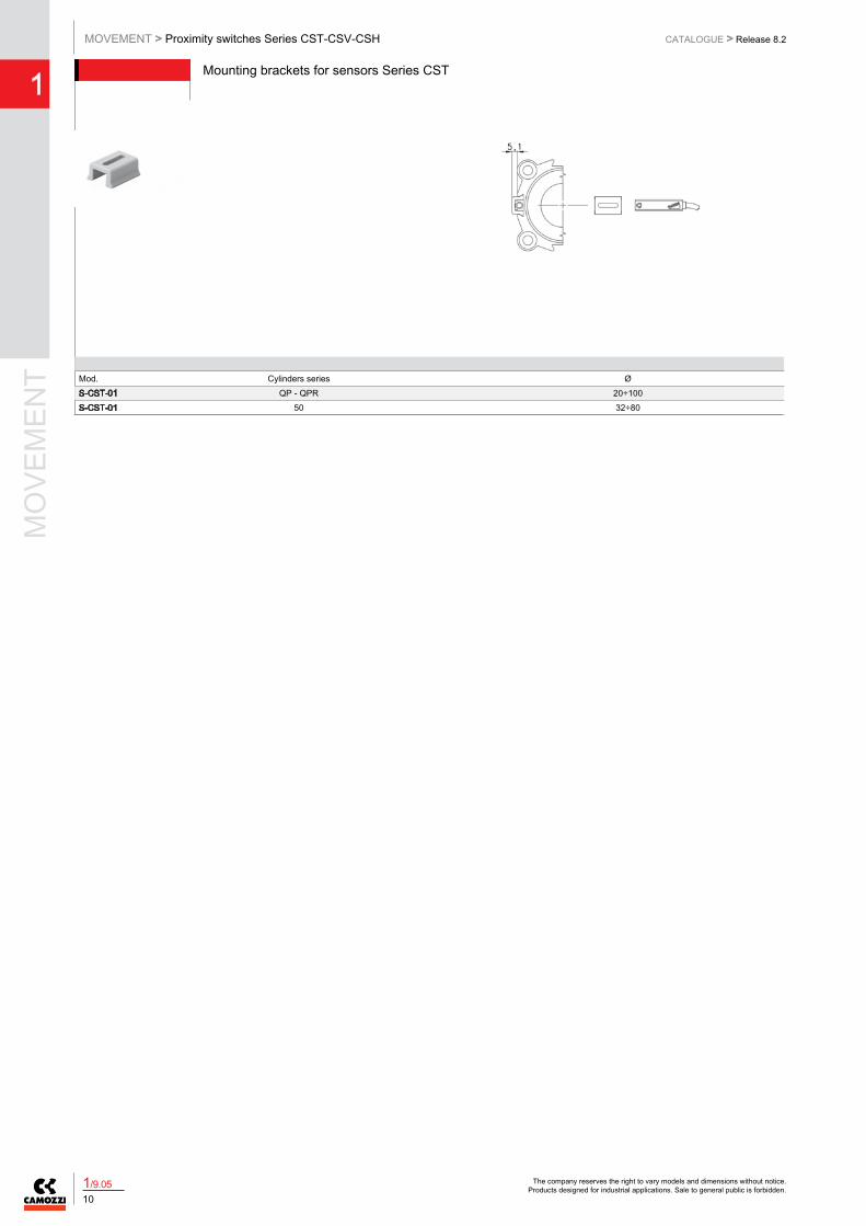
Mounting brackets for sensors Series CST
Mod. Cylinders series ØS-CST-01 QP - QPR 20÷100S-CST-01 50 32÷80
Mounting brackets for sensors Series CST and CSH
Mod. Cylinders series ØS-CST-25 60 32÷63S-CST-26 60 80 - 100S-CST-27 60 125S-CST-28 40 160 - 200
Mounting brackets for sensors Series CST and CSH
For cylinders series 60 mounted with guides series 45NHT or 45NHB.
Mod. Cylinders series ØS-CST-45N1 60 32÷63S-CST-45N2 60 80 - 100
The company reserves the right to vary models and dimensions without notice. Products designed for industrial applications. Sale to general public is forbidden.
MOVEMENT > Proximity switches Series CST-CSV-CSHCATALOGUE > Release 8.2
1
111/9.05
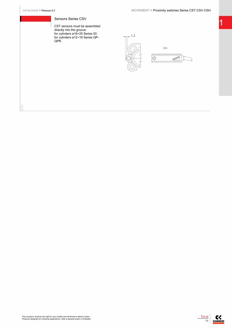
Sensors Series CSV
CST sensors must be assembleddirectly into the groove:for cylinders ø16÷25 Series 50for cylinders ø12÷16 Series QP-QPR.
Sensors Series CST - CSH
CST sensors must be assembleddirectly into the groove:for cylinders Series 31-31Rfor cylinders Series QCfor cylinders Series 61and for cylinders Series 69.
Slot cover profile Mod. S-CST-500
Supplied with 500 mm tube
Mod.S-CST-500
Slot cover profile for cylinders Series: 31 - 31 tandem and multi-position - QCT - QCB - QCBT-QCBF - 61 - 69 - 32 - 32 tandem and multi-position.