1. Layer3 Air Interface Messages 0111_06
563
ED 06 RELEASED LAYER 3 MESSAGE DICTIONARY - AIR INTERFACE EVOLIUM 0111_06.doc 14/03/2007 3BK 11203 0111 DSZZA 1/ 563 Site VELIZY EVOLIUM™ SAS Originators Didier Esclamadon LAYER 3 MESSAGE DICTIONARY - AIR INTERFACE Release B9 System : ALCATEL BSS Sub-system : SYS-TLA Document Category : PRODUCT DEFINITION ABSTRACT This document describes the layer 3 messages for the Air interface. Approvals Name App. R.MAUGER SYT Manager C. LEJEUNE DPM SYT ZHANG YI DPM BCC Name App. U. TISCH DPM BTS
-
Upload
nghia-huynh-quang -
Category
Documents
-
view
207 -
download
0
Transcript of 1. Layer3 Air Interface Messages 0111_06
7/11/2019 1. Layer3 Air Interface Messages 0111_06
http://slidepdf.com/reader/full/1-layer3-air-interface-messages-011106 1/562
ED 06 RELEASED LAYER 3 MESSAGE DICTIONARY - AIR INTERFACE
EVOLIUM 0111_06.doc14/03/2007 3BK 11203 0111 DSZZA 1/ 563
SiteVELIZY
EVOLIUM™ SAS
Originators
Didier Esclamadon
LAYER 3 MESSAGE DICTIONARY - AIR INTERFACE
Release B9
System : ALCATEL BSS
Sub-system : SYS-TLA
Document Category : PRODUCT DEFINITION
ABSTRACT
This document describes the layer 3 messages for the Air interface.
Approvals
NameApp.
R.MAUGERSYT Manager
C. LEJEUNEDPM SYT
ZHANG YIDPM BCC
NameApp.
U. TISCHDPM BTS
7/11/2019 1. Layer3 Air Interface Messages 0111_06
http://slidepdf.com/reader/full/1-layer3-air-interface-messages-011106 2/562
ED 06 RELEASED LAYER 3 MESSAGE DICTIONARY - AIR INTERFACE
EVOLIUM 0111_06.doc14/03/2007 3BK 11203 0111 DSZZA 2/ 563
REVIEW
HISTORY
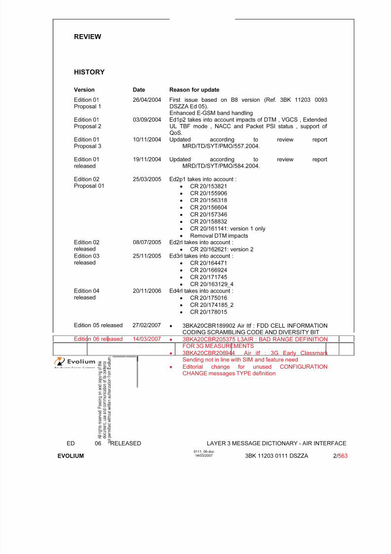
Version Date Reason for update
Edition 01Proposal 1
26/04/2004 First issue based on B8 version (Ref. 3BK 11203 0093DSZZA Ed 05).Enhanced E-GSM band handling
Edition 01Proposal 2
03/09/2004 Ed1p2 takes into account impacts of DTM , VGCS , ExtendedUL TBF mode , NACC and Packet PSI status , support of QoS.
Edition 01Proposal 3
10/11/2004 Updated according to review reportMRD/TD/SYT/PMO/557.2004.
Edition 01released
19/11/2004 Updated according to review reportMRD/TD/SYT/PMO/584.2004.
Edition 02Proposal 01
25/03/2005 Ed2p1 takes into account :
• CR 20/153821
• CR 20/155906
• CR 20/156318
• CR 20/156604
• CR 20/157346
• CR 20/158832
• CR 20/161141: version 1 only
• Removal DTM impactsEdition 02released
08/07/2005 Ed2rl takes into account :
• CR 20/162621: version 2
Edition 03released
25/11/2005 Ed3rl takes into account :• CR 20/164471
• CR 20/166924
• CR 20/171745
• CR 20/163129_4Edition 04released
20/11/2006 Ed4rl takes into account :
• CR 20/175016
• CR 20/174185_2
• CR 20/178015
Edition 05 released 27/02/2007 • 3BKA20CBR189902 Air Itf : FDD CELL INFORMATIONCODING SCRAMBLING CODE AND DIVERSITY BIT
Edition 06 released 14/03/2007 • 3BKA20CBR205375 L3AIR : BAD RANGE DEFINITIONFOR 3G MEASUREMENTS
• 3BKA20CBR206944 Air itf : 3G Early ClassmarkSending not in line with SIM and feature need
• Editorial change for unused CONFIGURATIONCHANGE messages TYPE definition

7/11/2019 1. Layer3 Air Interface Messages 0111_06
http://slidepdf.com/reader/full/1-layer3-air-interface-messages-011106 3/562
ED 06 RELEASED LAYER 3 MESSAGE DICTIONARY - AIR INTERFACE
EVOLIUM 0111_06.doc14/03/2007 3BK 11203 0111 DSZZA 3/ 563
TABLE OF CONTENTS
INTERNAL REFERENCED DOCUMENTS......................................................................................... 10 REFERENCED DOCUMENTS ............................................................................................................ 10 RELATED DOCUMENTS.................................................................................................................... 12 PREFACE ............................................................................................................................................ 12 OPEN POINTS / RESTRICTIONS....................................................................................................... 12 1 INTRODUCTION............................................................................................................................. 13
1.1 Scope ................................................................................................................................... 13 2 GENERAL PRESENTATION ......................................................................................................... 14
2.1 Preliminaries........................................................................................................................ 14 2.2 Messages presentation ...................................................................................................... 14
2.2.1 Introduction.................................................................................................................... 14 2.2.2 The general overview.................................................................................................... 14
2.3 The information element description................................................................................ 15 2.3.1 The bit description......................................................................................................... 16
2.4
Summary description ......................................................................................................... 16
2.5 Cross reference................................................................................................................... 16 3 LIST OF THE MESSAGES............................................................................................................. 17 4 CROSS REFERENCE ON INFORMATION ELEMENTS .............................................................. 20 5 DESCRIPTION OF THE HEADER ON THE RADIO INTERFACE................................................ 27
5.1 GENERAL DESCRIPTION FOR STANDARD L3 MESSAGE ............................................ 27 5.1.1 PROTOCOL DISCRIMINATOR.................................................................................... 27 5.1.2 TRANSACTION IDENTIFIER/SKIP INDICATOR ......................................................... 28 5.1.3 MESSAGE TYPE .......................................................................................................... 28
5.2 GENERAL DESCRIPTION FOR NON STANDARD L3 MESSAGE ................................... 32 5.2.1 Messages using the short header format.................................................................... 32 5.2.2 Other formats ................................................................................................................ 33
6 RADIO INTERFACE MESSAGES FOR GSM................................................................................ 34 6.1 APPLICATION INFORMATION........................................................................................... 35
6.1.1 General description....................................................................................................... 35 6.1.2 APDU ID........................................................................................................................ 36 6.1.3 APDU Flags................................................................................................................... 36 6.1.4 APDU Data.................................................................................................................... 37
6.2 ASSIGNMENT COMMAND.................................................................................................. 41 GENERAL DESCRIPTION ........................................................................................................ 43 6.2.2 Channel Description / CHANNEL DESCRIPTION - Phase 1 ....................................... 48 6.2.3 Description of the First Channel, after time / CHANNEL DESCRIPTION 2 - Phase 2. 50 6.2.4 POWER COMMAND..................................................................................................... 52 6.2.5 FREQUENCY LIST, after time / FREQUENCY LIST.................................................... 54 6.2.6 CELL CHANNEL DESCRIPTION ................................................................................. 57 6.2.7 Description of the multislot configuration / MULTISLOT ALLOCATION....................... 58 6.2.8 Mode of the First Channel (Channel Set 1) / CHANNEL MODE.................................. 59 6.2.9 MOBILE ALLOCATION, after time / MOBILE ALLOCATION....................................... 60 6.2.10 VGCS target mode Indication ....................................................................................... 60 6.2.11 MULTIRATE CONFIGURATION................................................................................... 62
6.3 ASSIGNMENT COMPLETE................................................................................................. 65 6.3.1 GENERAL DESCRIPTION ........................................................................................... 66 6.3.2 RR CAUSE.................................................................................................................... 66
6.4 ASSIGNMENT FAILURE ..................................................................................................... 67 6.4.1 GENERAL DESCRIPTION ........................................................................................... 68 6.4.2 RR CAUSE.................................................................................................................... 68
6.5 CHANNEL MODE MODIFY ................................................................................................. 69 6.5.1 GENERAL DESCRIPTION ........................................................................................... 70

7/11/2019 1. Layer3 Air Interface Messages 0111_06
http://slidepdf.com/reader/full/1-layer3-air-interface-messages-011106 4/562
ED 06 RELEASED LAYER 3 MESSAGE DICTIONARY - AIR INTERFACE
EVOLIUM 0111_06.doc14/03/2007 3BK 11203 0111 DSZZA 4/ 563
6.5.2 CHANNEL DESCRIPTION - Phase 1........................................................................... 71 6.5.3 Channel Description / CHANNEL DESCRIPTION 2 - Phase2 ..................................... 73 6.5.4 CHANNEL MODE ......................................................................................................... 76 6.5.5 MULTIRATE CONFIGURATION................................................................................... 77
6.6 CHANNEL MODE MODIFY ACK......................................................................................... 80 6.6.1 GENERAL DESCRIPTION ........................................................................................... 81 6.6.2 CHANNEL DESCRIPTION - Phase 1........................................................................... 81 6.6.3
CHANNEL DESCRIPTION 2 - Phase2......................................................................... 83
6.6.4 CHANNEL MODE ......................................................................................................... 86
6.7 CHANNEL RELEASE .......................................................................................................... 87 6.7.1 GENERAL DESCRIPTION ........................................................................................... 88 6.7.2 RR CAUSE.................................................................................................................... 90 6.7.3 BA RANGE.................................................................................................................... 91 6.7.4 Group channel description ............................................................................................ 91 6.7.5 GPRS RESUMPTION................................................................................................... 94 6.7.6 Cell Channel Description............................................................................................... 95
6.8 CHANNEL REQUEST........................................................................................................ 101 6.8.1 GENERAL DESCRIPTION ......................................................................................... 102
6.9 CIPHERING MODE COMMAND........................................................................................ 104 6.9.1 GENERAL DESCRIPTION ......................................................................................... 105 6.9.2
CIPHER MODE SETTING .......................................................................................... 105
6.9.3 CIPHER RESPONSE.................................................................................................. 106
6.10 DATA INDICATION............................................................................................................ 107 6.10.1 GENERAL DESCRIPTION ......................................................................................... 108 6.10.2 MOBILE EQUIPMENT IDENTITY............................................................................... 108
6.11 CLASSMARK CHANGE .................................................................................................... 110 6.11.1 GENERAL DESCRIPTION ......................................................................................... 111 6.11.2 MS CLASSMARK 2 - GSM Phase 1........................................................................... 112 6.11.3 MS CLASSMARK 2 - GSM Phase 2........................................................................... 114 6.11.4 MS CLASSMARK 3..................................................................................................... 117
6.12 CLASSMARK ENQUIRY.................................................................................................... 126 6.12.1 GENERAL DESCRIPTION ......................................................................................... 126 6.12.2 Classmark Enquiry Mask ............................................................................................ 127
6.13 CM RE-ESTABLISHMENT REQUEST.............................................................................. 128 6.13.1 GENERAL DESCRIPTION ......................................................................................... 129 6.13.2 CIPHERING KEY SEQUENCE NUMBER.................................................................. 132 6.13.3 MS CLASSMARK 2 - GSM Phase 1........................................................................... 133 6.13.4 MS CLASSMARK 2 - GSM Phase 2........................................................................... 134 6.13.5 MOBILE IDENTITY ..................................................................................................... 137 6.13.6 LOCATION AREA IDENTIFICATION ......................................................................... 138
6.14 CM SERVICE REQUEST ................................................................................................... 139 6.14.1 GENERAL DESCRIPTION ......................................................................................... 140 6.14.2 CM SERVICE TYPE.................................................................................................... 143 6.14.3 CIPHERING KEY SEQUENCE NUMBER.................................................................. 144 6.14.4 MS CLASSMARK 2 - GSM Phase 1........................................................................... 145 6.14.5 MS CLASSMARK 2 - GSM Phase 2........................................................................... 146 6.14.6 MOBILE IDENTITY ..................................................................................................... 149 6.14.7 Priority Level................................................................................................................ 150
6.15 E-GPRS PACKET CHANNEL REQUEST ......................................................................... 151 6.15.1 GENERAL DESCRIPTION ......................................................................................... 151
6.16 EXTENDED MEASUREMENT ORDER............................................................................. 154 6.16.1 GENERAL DESCRIPTION ......................................................................................... 155 6.16.2 EXTENDED MEASUREMENT FREQUENCY LIST ................................................... 155
6.17 EXTENDED MEASUREMENT REPORT........................................................................... 156 6.17.1 GENERAL DESCRIPTION ......................................................................................... 157 6.17.2 EXTENDED MEASUREMENT RESULTS.................................................................. 158
6.18 GPRS SUSPENSION REQUEST....................................................................................... 160 6.18.1 GENERAL DESCRIPTION ......................................................................................... 161 6.18.2 TEMPORARY LOGICAL LINK IDENTIFIER (TLLI) .................................................... 161 6.18.3 ROUTING AREA IDENTIFICATION (RAI).................................................................. 162

7/11/2019 1. Layer3 Air Interface Messages 0111_06
http://slidepdf.com/reader/full/1-layer3-air-interface-messages-011106 5/562
ED 06 RELEASED LAYER 3 MESSAGE DICTIONARY - AIR INTERFACE
EVOLIUM 0111_06.doc14/03/2007 3BK 11203 0111 DSZZA 5/ 563
6.18.4 SUSPENSION CAUSE ............................................................................................... 163 6.19 HANDOVER ACCESS ....................................................................................................... 164
6.19.1 GENERAL DESCRIPTION ......................................................................................... 164 6.20 HANDOVER COMMAND................................................................................................... 165
6.20.1 GENERAL DESCRIPTION ......................................................................................... 167 6.20.2 CELL DESCRIPTION.................................................................................................. 174 6.20.3 Channel Description / CHANNEL DESCRIPTION - Phase 1 ..................................... 175 6.20.4
Description of the first channel, after time / CHANNEL DESCRIPTION 2 - Phase 2. 177
6.20.5 HANDOVER REFERENCE......................................................................................... 179 6.20.6 POWER COMMAND AND ACCESS TYPE................................................................ 180 6.20.7 SYNCHRONIZATION INDICATION ........................................................................... 182 6.20.8 FREQUENCY SHORT LIST ....................................................................................... 183 6.20.9 FREQUENCY LIST ..................................................................................................... 186 6.20.10 CELL CHANNEL DESCRIPTION ............................................................................... 190 6.20.11 MULTISLOT ALLOCATION........................................................................................ 191 6.20.12 CHANNEL MODE ....................................................................................................... 192 6.20.13 FREQUENCY CHANNEL SEQUENCE...................................................................... 193 6.20.14 MOBILE ALLOCATION, after time.............................................................................. 194 6.20.15 CIPHER MODE SETTING .......................................................................................... 195 6.20.16 MULTIRATE CONFIGURATION................................................................................. 196
6.21
HANDOVER COMPLETE .................................................................................................. 199
6.21.1 GENERAL DESCRIPTION ......................................................................................... 200 6.21.2 RR CAUSE.................................................................................................................. 200
6.22 HANDOVER FAILURE....................................................................................................... 201 6.22.1 GENERAL DESCRIPTION ......................................................................................... 202 6.22.2 RR CAUSE.................................................................................................................. 202
6.23 IMMEDIATE ASSIGNMENT............................................................................................... 203 6.23.1 GENERAL DESCRIPTION ......................................................................................... 204 6.23.2 L2 PSEUDO LENGTH ................................................................................................ 206 6.23.3 PAGE MODE / Dedicated mode or TBF ..................................................................... 207 6.23.4 CHANNEL DESCRIPTION ......................................................................................... 209 6.23.5 PACKET CHANNEL DESCRIPTION.......................................................................... 210 6.23.6 REQUEST REFERENCE............................................................................................ 212 6.23.7 TIMING ADVANCE ..................................................................................................... 213 6.23.8 MOBILE ALLOCATION............................................................................................... 214 6.23.9 IA REST OCTETS....................................................................................................... 215
6.24 IMMEDIATE ASSIGNMENT EXTENDED.......................................................................... 218 6.24.1 GENERAL DESCRIPTION ......................................................................................... 219 6.24.2 L2 PSEUDO LENGTH ................................................................................................ 220 6.24.3 PAGE MODE............................................................................................................... 220 6.24.4 CHANNEL DESCRIPTION ......................................................................................... 221 6.24.5 REQUEST REFERENCE............................................................................................ 223 6.24.6 TIMING ADVANCE ..................................................................................................... 224 6.24.7 MOBILE ALLOCATION............................................................................................... 225 6.24.8 IAX REST OCTETS .................................................................................................... 226
6.25 IMMEDIATE ASSIGNMENT REJECT ............................................................................... 227 6.25.1 GENERAL DESCRIPTION ......................................................................................... 228 6.25.2 L2 PSEUDO LENGTH ................................................................................................ 229 6.25.3 PAGE MODE............................................................................................................... 229 6.25.4 REQUEST REFERENCE............................................................................................ 230 6.25.5 WAIT INDICATION...................................................................................................... 232 6.25.6 IAR REST OCTETS .................................................................................................... 232
6.26 IMMEDIATE SETUP........................................................................................................... 234 6.26.1 GENERAL DESCRIPTION ......................................................................................... 235 6.26.2 CIPHERING KEY SEQUENCE NUMBER.................................................................. 235 6.26.3 MS CLASSMARK 2..................................................................................................... 237 6.26.4 MOBILE IDENTITY ..................................................................................................... 240 6.26.5 Group Identity.............................................................................................................. 241
6.27 IMMEDIATE SETUP 2........................................................................................................ 242 6.27.1 GENERAL DESCRIPTION ......................................................................................... 243

7/11/2019 1. Layer3 Air Interface Messages 0111_06
http://slidepdf.com/reader/full/1-layer3-air-interface-messages-011106 6/562
ED 06 RELEASED LAYER 3 MESSAGE DICTIONARY - AIR INTERFACE
EVOLIUM 0111_06.doc14/03/2007 3BK 11203 0111 DSZZA 6/ 563
6.27.2 CIPHERING KEY SEQUENCE NUMBER.................................................................. 244 6.27.3 MS CLASSMARK 2..................................................................................................... 245 6.27.4 TMSI............................................................................................................................ 248 6.27.5 Group Identity.............................................................................................................. 248 6.27.6 Compressed otdi ......................................................................................................... 249
6.28 IMSI DETACH INDICATION .............................................................................................. 250 6.28.1 GENERAL DESCRIPTION ......................................................................................... 251 6.28.2
MS CLASSMARK 1..................................................................................................... 252
6.28.3 MOBILE IDENTITY ..................................................................................................... 253
6.29 INTER SYSTEM TO UTRAN HANDOVER COMMAND.................................................... 254 6.29.1GENERAL DESCRIPTION ............................................................................................ 255 6.29.2 Handover to UTRAN Command ................................................................................... 255
6.30 LOCATION UPDATING REQUEST................................................................................... 256 6.30.1 GENERAL DESCRIPTION ......................................................................................... 257 6.30.2 LOCATION UPDATING TYPE.................................................................................... 259 6.30.3 CIPHERING KEY SEQUENCE NUMBER.................................................................. 259 6.30.4 LOCATION AREA IDENTIFICATION ......................................................................... 261 6.30.5 MS CLASSMARK 1..................................................................................................... 262 6.30.6 MOBILE IDENTITY ..................................................................................................... 263
6.31 MEASUREMENT INFORMATION ..................................................................................... 264 6.30.1 GENERAL DESCRIPTION ........................................................................................... 265
6.30.2 MESUREMENT INFORMATION VALUE PART........................................................... 266
6.32 MEASUREMENT REPORT................................................................................................ 274 6.32.1 GENERAL DESCRIPTION ......................................................................................... 275 6.32.2 MEASUREMENT RESULTS....................................................................................... 276
6.33 NOTIFICATION/FACCH..................................................................................................... 279 6.33.1 GENERAL DESCRIPTION ......................................................................................... 280 6.33.2 NOTIFICATION/FACCH with Group call Information ................................................. 280 6.33.3 PARAMETER DESCRIPTION .................................................................................... 283 6.33.4 NOTIFICATION/FACCH with paging Information....................................................... 291
6.34 NOTIFICATION/NCH..........................................................................................................294 6.34.1 GENERAL DESCRIPTION ......................................................................................... 295 6.34.2 PARAMETER DESCRIPTION .................................................................................... 298
6.35 NOTIFICATION RESPONSE ............................................................................................. 300 6.35.1 GENERAL DESCRIPTION ......................................................................................... 301 6.35.2 MS Classmark 2 .......................................................................................................... 302 6.35.3 Mobile Identity ............................................................................................................. 305 6.35.4 Group or broadcast Call reference.............................................................................. 306
6.36 PAGING REQUEST TYPE 1 .............................................................................................. 307 6.36.1 GENERAL DESCRIPTION ......................................................................................... 308 6.36.2 PAGE MODE............................................................................................................... 309 6.36.3 CHANNELS NEEDED FOR MOBILES 1 & 2 ............................................................. 310 6.36.4 MOBILE IDENTITY ..................................................................................................... 310 6.36.5 P1 REST OCTETS...................................................................................................... 311
6.37 PAGING REQUEST TYPE 2 .............................................................................................. 316 6.37.1 PAGE MODE............................................................................................................... 318 6.37.2 CHANNELS NEEDED FOR MOBILES 1 & 2 ............................................................. 318 6.37.3 (P)TMSI....................................................................................................................... 319 6.37.4 MOBILE IDENTITY ..................................................................................................... 319 6.37.5 P2 REST OCTETS...................................................................................................... 321
6.38 PAGING REQUEST TYPE 3 .............................................................................................. 324 6.38.1 GENERAL DESCRIPTION ......................................................................................... 325 6.38.2 PAGE MODE............................................................................................................... 325 6.38.3 CHANNELS NEEDED FOR MOBILES 1 & 2 ............................................................. 326 6.38.4 (P)TMSI....................................................................................................................... 326 6.38.5 P3 REST OCTETS...................................................................................................... 327
6.39 PAGING RESPONSE......................................................................................................... 329 6.39.1 GENERAL DESCRIPTION ......................................................................................... 330 6.39.2 CIPHERING KEY SEQUENCE NUMBER.................................................................. 331 6.39.3 MS CLASSMARK 2 - GSM Phase 1........................................................................... 332
7/11/2019 1. Layer3 Air Interface Messages 0111_06
http://slidepdf.com/reader/full/1-layer3-air-interface-messages-011106 7/562
ED 06 RELEASED LAYER 3 MESSAGE DICTIONARY - AIR INTERFACE
EVOLIUM 0111_06.doc14/03/2007 3BK 11203 0111 DSZZA 7/ 563
6.39.4 MS CLASSMARK 2 - GSM Phase 2........................................................................... 333 6.39.5 MOBILE IDENTITY ..................................................................................................... 336
6.40 PHYSICAL INFORMATION ............................................................................................... 338 6.40.1 GENERAL DESCRIPTION ......................................................................................... 338 6.40.2 TIMING ADVANCE ..................................................................................................... 339
6.41 SYNCHRONIZATION CHANNEL INFORMATION............................................................ 340 6.41.1 GENERAL DESCRIPTION ......................................................................................... 340
6.42
SYSTEM INFORMATION TYPE 1 ..................................................................................... 341
6.42.1 GENERAL DESCRIPTION ......................................................................................... 342 6.42.2 CELL CHANNEL DESCRIPTION ............................................................................... 343 6.42.3 RACH CONTROL PARAMETERS.............................................................................. 350 6.42.4 SI 1 REST OCTETS.................................................................................................... 351
6.43 SYSTEM INFORMATION TYPE 2 ..................................................................................... 353 6.43.1 GENERAL DESCRIPTION ......................................................................................... 354 6.43.2 BCCH FREQUENCY LIST / NEIGHBOUR CELLS DESCRIPTION........................... 355 6.43.3 NCC PERMITTED....................................................................................................... 361 6.43.4 RACH CONTROL PARAMETERS.............................................................................. 361
6.44 SYSTEM INFORMATION TYPE 2BIS ............................................................................... 363 6.44.1 GENERAL DESCRIPTION ......................................................................................... 364 6.44.2 EXTENDED BCCH FREQUENCY LIST / NEIGHBOUR CELLS DESCRIPTION...... 364 6.44.3 RACH CONTROL PARAMETERS.............................................................................. 370 6.44.4 SI 2BIS REST OCTETS.............................................................................................. 371
6.45 SYSTEM INFORMATION TYPE 2TER.............................................................................. 372 6.45.1 GENERAL DESCRIPTION ......................................................................................... 373 6.45.2 EXTENDED BCCH FREQUENCY LIST / NEIGHBOUR CELLS DESCRIPTION 2... 375 6.45.3 SI 2TER REST OCTETS ............................................................................................ 381
6.46 SYSTEM INFORMATION TYPE 2QUATER...................................................................... 384 6.46.1 GENERAL DESCRIPTION ......................................................................................... 385 6.46.2 SI 2QUATER REST OCTETS..................................................................................... 385
6.47 SYSTEM INFORMATION TYPE 3 ..................................................................................... 389 6.47.1 GENERAL DESCRIPTION ......................................................................................... 390 6.47.2 CELL IDENTITY.......................................................................................................... 395 6.47.3 LOCATION AREA IDENTIFICATION ......................................................................... 395 6.47.4 CONTROL CHANNEL DESCRIPTION....................................................................... 397 6.47.5 CELL OPTIONS (BCCH) ............................................................................................ 399 6.47.6 CELL SELECTION PARAMETERS............................................................................ 400 6.47.7 RACH CONTROL PARAMETER................................................................................ 401 6.47.8 SI 3 REST OCTETS.................................................................................................... 402
6.48 SYSTEM INFORMATION TYPE 4 ..................................................................................... 405 6.48.1 GENERAL DESCRIPTION ......................................................................................... 406 6.48.2 LOCATION AREA IDENTIFICATION ......................................................................... 409 6.48.3 CELL SELECTION PARAMETERS............................................................................ 410 6.48.4 RACH CONTROL PARAMETER................................................................................ 411 6.48.5 CBCH CHANNEL DESCRIPTION.............................................................................. 412 6.48.6 CBCH MOBILE ALLOCATION.................................................................................... 414 6.48.7 SI 4 REST OCTETS.................................................................................................... 415
6.49 SYSTEM INFORMATION TYPE 5 ..................................................................................... 417 6.49.1 GENERAL DESCRIPTION ......................................................................................... 418 6.49.2 BCCH FREQUENCY LIST / NEIGHBOUR CELLS DESCRIPTION........................... 419
6.50 SYSTEM INFORMATION TYPE 5BIS ............................................................................... 425 6.50.1 GENERAL DESCRIPTION ......................................................................................... 426 6.50.2 EXTENSION OF THE BCCH FREQUENCY LIST / NEIGHBOUR CELLS
DESCRIPTION...................................................................................................................... 427 6.51 SYSTEM INFORMATION TYPE 5TER.............................................................................. 432
6.51.1 GENERAL DESCRIPTION ......................................................................................... 433 6.51.2 EXTENDED BCCH FREQUENCY LIST / NEIGHBOUR CELLS DESCRIPTION 2... 434
6.52 SYSTEM INFORMATION TYPE 6 ..................................................................................... 440 6.52.1 GENERAL DESCRIPTION ......................................................................................... 441 6.52.2 CELL IDENTITY.......................................................................................................... 442 6.52.3 LOCATION AREA IDENTIFICATION ......................................................................... 442

7/11/2019 1. Layer3 Air Interface Messages 0111_06
http://slidepdf.com/reader/full/1-layer3-air-interface-messages-011106 8/562
ED 06 RELEASED LAYER 3 MESSAGE DICTIONARY - AIR INTERFACE
EVOLIUM 0111_06.doc14/03/2007 3BK 11203 0111 DSZZA 8/ 563
6.52.4 CELL OPTIONS (SACCH).......................................................................................... 444 6.52.5 NCC PERMITTED....................................................................................................... 445 6.52.6 SI 6 Rest octets ........................................................................................................... 445
6.53 SYSTEM INFORMATION TYPE 7 and 8........................................................................... 448 6.53.1 GENERAL DESCRIPTION ......................................................................................... 449 6.53.2 PRIO_THR .................................................................................................................. 451 6.53.3 LSA_OFFSET ............................................................................................................. 451 6.53.4
CELL IDENTITY.......................................................................................................... 452
6.53.5 LSA ID INFORMATION............................................................................................... 453
6.54 SYSTEM INFORMATION TYPE 10 ................................................................................... 454 6.54.1 GENERAL DESCRIPTION ......................................................................................... 455 6.54.2 BA ind.......................................................................................................................... 467 6.54.3 First frequency............................................................................................................. 467 6.54.4 Bsic.............................................................................................................................. 468 6.54.5 Cell barred................................................................................................................... 468 6.54.6 La different .................................................................................................................. 468 6.54.7 Ms txpwr max cch........................................................................................................ 468 6.54.8 Rxlev access min ........................................................................................................ 468 6.54.9 Cell reselection offset.................................................................................................. 468 6.54.10 Temporary offset ......................................................................................................... 468 6.54.11
Penalty time................................................................................................................. 468
6.55 SYSTEM INFORMATION TYPE 13 ................................................................................... 469
6.55.1 GENERAL DESCRIPTION ......................................................................................... 470 6.55.2 BCCH_CHANGE_MARK............................................................................................ 474 6.55.3 SI_CHANGE_FIELD ................................................................................................... 474 6.55.4 SI13_CHANGE_MARK............................................................................................... 475 6.55.5 GPRS MOBILE ALLOCATION.................................................................................... 476 6.55.6 PRIORITY_ACCESS_THR......................................................................................... 477 6.55.7 NETWORK_CONTROL_ORDER............................................................................... 477 6.55.8 GPRS CELL OPTIONS............................................................................................... 478 6.55.9 GPRS POWER CONTROL PARAMETERS............................................................... 481 6.55.10 PSI1_REPEAT_PERIOD ............................................................................................ 482 6.55.11 PBCCH DESCRIPTION.............................................................................................. 482
6.56 SYSTEM INFORMATION TYPE 16 and 17....................................................................... 484 6.56.1 GENERAL DESCRIPTION ......................................................................................... 485 6.56.2 PRIO_THR .................................................................................................................. 487 6.56.3 LSA_OFFSET ............................................................................................................. 487 6.56.4 LSA ID INFORMATION............................................................................................... 487
6.57 TALKER INDICATION ....................................................................................................... 489 6.57.1 GENERAL DESCRIPTION ......................................................................................... 490 6.57.2 MS Classmark 2.......................................................................................................... 490 6.57.3 Mobile Identity ............................................................................................................. 494
6.58 UTRAN CLASSMARK CHANGE....................................................................................... 495 6.58.1 GENERAL DESCRIPTION ......................................................................................... 496 6.60.1 UTRAN CLASSMARK .................................................................................................. 496
6.59 UPLINK ACCESS............................................................................................................... 497 6.59.1 GENERAL DESCRIPTION ......................................................................................... 498 6.59.2 ESTABLISHMENT CAUSE AND RANDOM REFERENCE........................................ 498
6.60 UPLINK BUSY.................................................................................................................... 499 6.60.1 GENERAL DESCRIPTION ......................................................................................... 500
6.61 UPLINK FREE.................................................................................................................... 501 6.61.1 GENERAL DESCRIPTION ......................................................................................... 502 6.61.2 UPLINK ACCESS REQUEST..................................................................................... 502
6.62 UPLINK RELEASE............................................................................................................. 503 6.62.1 GENERAL DESCRIPTION ......................................................................................... 504 6.62.2 RR CAUSE.................................................................................................................. 504
6.63 VGCS UPLINK GRANT...................................................................................................... 505 6.63.1 GENERAL DESCRIPTION ......................................................................................... 505 6.63.2 REQUEST REFERENCE............................................................................................ 506 6.63.3 TIMING ADVANCE ..................................................................................................... 507

7/11/2019 1. Layer3 Air Interface Messages 0111_06
http://slidepdf.com/reader/full/1-layer3-air-interface-messages-011106 9/562
ED 06 RELEASED LAYER 3 MESSAGE DICTIONARY - AIR INTERFACE
EVOLIUM 0111_06.doc14/03/2007 3BK 11203 0111 DSZZA 9/ 563
7 RADIO INTERFACE MESSAGES FOR SMSCB......................................................................... 508 7.1 MESSAGE BLOCKS.......................................................................................................... 509
7.1.1 GENERAL DESCRIPTION ......................................................................................... 510 7.1.2 BLOCK TYPE.............................................................................................................. 512
7.2 SMSCB SCHEDULE MESSAGE....................................................................................... 513 7.2.1 GENERAL DESCRIPTION ......................................................................................... 514 7.2.2 SCHEDULE MESSAGE HEADER.............................................................................. 517 7.2.3
NEW CBSMS MESSAGE BITMAP............................................................................. 518
7.2.4 NEW CBSMS MESSAGE DESCRIPTION ................................................................. 518 7.2.5 OTHER MESSAGE DESCRIPTIONS......................................................................... 520
8 RADIO INTERFACE MESSAGES FOR (E)GPRS....................................................................... 521 8.1 RLC/MAC block structure ................................................................................................ 522
8.1.1 GPRS RLC/MAC block structure ................................................................................ 522 8.1.2 E-GPRS RLC/MAC block structure............................................................................. 522 8.1.3 RLC data blocks.......................................................................................................... 523 8.1.4 (E)GPRS RLC/MAC control blocks............................................................................. 527
8.2 EGPRS PACKET DOWNLINK ACK/NACK ...................................................................... 529 8.3 PACKET ACCESS REJECT.............................................................................................. 530 8.4 PACKET CELL CHANGE CONTINUE .............................................................................. 531 8.5 PACKET CELL CHANGE FAILURE ................................................................................. 532 8.6 PACKET CELL CHANGE NOTIFICATION ....................................................................... 533 8.7 PACKET CELL CHANGE ORDER.................................................................................... 534 8.8 PACKET CONTROL ACKNOWLEDGMENT.................................................................... 535 8.9 PACKET CHANNEL REQUEST........................................................................................ 536 8.10 PACKET DOWNLINK ACK/NACK.................................................................................... 537 8.11 PACKET DOWNLINK ASSIGNMENT............................................................................... 538 8.12 PACKET DOWNLINK DUMMY CONTROL BLOCK......................................................... 539 8.13 PACKET UPLINK DUMMY CONTROL BLOCK ............................................................... 540 8.14 PACKET MEASUREMENT ORDER.................................................................................. 541 8.15 PACKET MEASUREMENT REPORT................................................................................ 542 8.16 PACKET MOBILE TBF STATUS....................................................................................... 543 8.17 PACKET NEIGHBOUR CELL DATA................................................................................. 544 8.18
PACKET PAGING REQUEST ........................................................................................... 545
8.19 PACKET PDCH RELEASE................................................................................................ 546 8.20 PACKET POWER CONTROL/TIMING ADVANCE........................................................... 547 8.21 PACKET PSI STATUS....................................................................................................... 548 8.22 PACKET RESOURCE REQUEST ..................................................................................... 549 8.23 PACKET SERVING CELL DATA ...................................................................................... 550 8.24 PACKET SI STATUS ......................................................................................................... 551 8.25 PACKET SYSTEM INFORMATION TYPE 1 ..................................................................... 552 8.26 PACKET SYSTEM INFORMATION TYPE 2 ..................................................................... 553 8.27 PACKET SYSTEM INFORMATION TYPE 3 ..................................................................... 554 8.28 PACKET SYSTEM INFORMATION TYPE 3bis ................................................................ 555 8.29 PACKET SYSTEM INFORMATION TYPE 3quater .......................................................... 556 8.30 PACKET SYSTEM INFORMATION TYPE 8 ..................................................................... 557 8.31 PACKET SYSTEM INFORMATION TYPE 13 ................................................................... 558 8.32 PACKET TBF RELEASE ................................................................................................... 559 8.33 PACKET TIMESLOT RECONFIGURE.............................................................................. 560 8.34 PACKET UPLINK ACK/NACK .......................................................................................... 561 8.35 PACKET UPLINK ASSIGNMENT...................................................................................... 562
9 GLOSSARY.................................................................................................................................. 563

7/11/2019 1. Layer3 Air Interface Messages 0111_06
http://slidepdf.com/reader/full/1-layer3-air-interface-messages-011106 10/562
ED 06 RELEASED LAYER 3 MESSAGE DICTIONARY - AIR INTERFACE
EVOLIUM 0111_06.doc14/03/2007 3BK 11203 0111 DSZZA 10/ 563
INTERNAL REFERENCED DOCUMENTS
Not applicable
REFERENCED DOCUMENTS
3GPP references
Except a few exceptions, all the information contained in the dictionary is gathered from the following3GPP technical specifications.
3GPP TS 48.008 BSS-MSC Layer 3 Specification3GPP TS 48.058 BSC-BTS Layer 3 specification3GPP TS 44.018 Mobile Radio Interface Layer 3 Specification, Radio Resource Control Protocol3GPP TS 24.008 Mobile Radio Interface Layer 3 Specification, Core Network Protocols3GPP TS 44.060 MS - BSS interface ; Radio Link Control / Medium Access Control (RLC/MAC)
protocol3GPP TS 24.012 SMSCB support on the mobile radio interface3GPP TS 23.041 Technical realization of SMSCB
ALCATEL references
[1] 3BK 11202 0415 DSZZA Paging and Access Grant Control[2] 3BK 11202 0413 DSZZA Radio and Link Establishment[3] 3BK 11202 0412 DSZZA Normal Assignment Procedure[4] 3BK 11202 0156 DSZZA Ciphering procedure[5] 3BK 11202 0398 DSZZA Call Release[6] 3BK 11202 0399 DSZZA Internal channel changes[7] 3BK 11202 0386 DSZZA External channel changes[8] 3BK 11202 0287 DSZZA Channel Modification[9] 3BK 11202 0409 DSZZA Classmark Handling[10] 3BK 11202 0108 DSZZA Transparent Message Routing[11] 3BK 11202 0062 DSZZA Short Message Point-to-Point[12] 3BK 11202 0403 DSZZA Radio Measurement[13] 3BK 11202 0296 DSZZA DTX functional Specification[14] 3BK 11202 0295 DSZZA Power Control and radio link supervision[15] 3BK 11202 0387 DSZZA Resource allocation and management[16] 3BK 11202 0421 DSZZA Overload Control[17] 3BK 11202 0173 DSZZA Protocol Error handling[18] 3BK 11202 0069 DSZZA BSS trace procedure[19] 3BK 11202 0305 DSZZA BSS Init of Telecom part[20] 3BK 11204 0630 DSZZA FBS Logical Configuration Management[21] 3BK 11202 0416 DSZZA BSS Global Reset[22] 3BK 11202 0299 DSZZA Reset Circuit and Blocking[23] 3BK 11202 0329 DSZZA SMS Cell Broadcast[24] 3BK 11202 0389 DSZZA System Information Management[25] 3BK 11202 0301 DSZZA TFO Functional Specification[26] 3BK 11203 0103 DSZZA BSS Telecom Parameters[27] 3BK 11203 0102 DSZZA BSS Counters Catalogue[28] 3BK 11202 0337 DSZZA LCS Functional Specification[29] 3BK 11202 0391 DSZZA RRM PCC[30] 3BK 11202 0392 DSZZA RLC[31] 3BK 11202 0393 DSZZA MAC[32] 3BK 11202 0395 DSZZA BSCGP[33] 3BK 11202 0417 DSZZA BSSGP[34] 3BK 11202 0390 DSZZA RRM PRH[35] 3BK 10202 0405 DSZZA ASCI Functional Specification
[36] 3BK 10202 0414 DSZZA LAPDm Functional Specification[37] 3BK 10202 0388 DSZZA Frequency Encoding Algorithm

7/11/2019 1. Layer3 Air Interface Messages 0111_06
http://slidepdf.com/reader/full/1-layer3-air-interface-messages-011106 11/562
ED 06 RELEASED LAYER 3 MESSAGE DICTIONARY - AIR INTERFACE
EVOLIUM 0111_06.doc14/03/2007 3BK 11203 0111 DSZZA 11/ 563

7/11/2019 1. Layer3 Air Interface Messages 0111_06
http://slidepdf.com/reader/full/1-layer3-air-interface-messages-011106 12/562
ED 06 RELEASED LAYER 3 MESSAGE DICTIONARY - AIR INTERFACE
EVOLIUM 0111_06.doc14/03/2007 3BK 11203 0111 DSZZA 12/ 563
RELATED DOCUMENTS
Not applicable
PREFACE
OPEN POINTS / RESTRICTIONS
7/11/2019 1. Layer3 Air Interface Messages 0111_06
http://slidepdf.com/reader/full/1-layer3-air-interface-messages-011106 13/562
ED 06 RELEASED LAYER 3 MESSAGE DICTIONARY - AIR INTERFACE
EVOLIUM 0111_06.doc14/03/2007 3BK 11203 0111 DSZZA 13/ 563
1 INTRODUCTION
1.1 Scope
This volume of the message dictionary details the non-transparent messages handled by the AlcatelBSS over the radio interface.

7/11/2019 1. Layer3 Air Interface Messages 0111_06
http://slidepdf.com/reader/full/1-layer3-air-interface-messages-011106 14/562
ED 06 RELEASED LAYER 3 MESSAGE DICTIONARY - AIR INTERFACE
EVOLIUM 0111_06.doc14/03/2007 3BK 11203 0111 DSZZA 14/ 563
2 GENERAL PRESENTATION
2.1 Preliminaries
Each message is described in the same way:
• A general overview,
• A detailed description of the Information Elements,
• A bit description.
The messages dictionary includes also in this part:
• A summary of all the messages described into the dictionary,
• A cross reference of all the Information Elements. This allows finding all the messages in whichone Information Element appears.
2.2 Messages presentation
2.2.1 Introduction
All the messages are organised alphabetically under the relevant interface (SMSCB and GPRSmessages are gathered each in a dedicated section). Three parts are given for each messages:
• a general overview:
It is a general description of the message including the Information Elements list, the maximumand minimum lengths in octets, the normal and abnormal following events.
• A detailed description of the Information Elements:
It is mainly the use of the Information Element within the BSS entities.
• A Bit Description:
It is a bit presentation of the message as it is received or transmitted over the involved interfaces.
2.2.2 The general overview
It is the first page for each message. It includes:
NAME field:The name of the message.
INTERFACE field:The list of three Interfaces
CHANNEL/USAGE field:According to the involved interface, it is the radio channel definition or the fact that the message istransparent or not for the BTS. When the box is empty, the message is not used on this interface.
3GPP-REF. field:It is the reference to a 3GPP technical specification.
FUNCTION field:It is the description of the function of the message. This is extracted from the 3GPP technical
specifications.

7/11/2019 1. Layer3 Air Interface Messages 0111_06
http://slidepdf.com/reader/full/1-layer3-air-interface-messages-011106 15/562
ED 06 RELEASED LAYER 3 MESSAGE DICTIONARY - AIR INTERFACE
EVOLIUM 0111_06.doc14/03/2007 3BK 11203 0111 DSZZA 15/ 563
DIRECTION field:It is the direction of the message from one entity of the BSS or MS to another one.
INFORMATION ELEMENT LIST field:It is the list of all the Information Elements. For each Information Element the following information isgiven:
- Mandatory or Optional,
- Fixed or Variable length,
- The length in bytes,
- Some short comments.For a full description of the use of 'M', 'C', 'L', 'O' and 'V', refer to 3GPP TS 04.07. These rules are alsoused for SMSCB IEs although they are not defined in 3GPP TS.
IMPLEMENTATION MAXIMUM LENGTH field:It is the total of all used information elements, mandatory or optional. When the length is fixed for allparameters, a unique value is given. When not, a range is given ("minimum length" - "maximumlength")
FOLLOWING EVENT field:It is the description of following events (for specific procedure) for the normal and abnormal cases.
TIMER field:It is the name of the Timers (started or stopped) associated with the message.
SPECIFICATION DOC. REF. field:It is the reference of relevant ALCATEL document.
2.3 The information element description
One page (or more) per Information Element (The classification of the following pages respects the
order given by 3GPP TS).On the Radio Interface, if the Information element is mandatory, the Information element identifier (IEI)is not present (it is marked with a star). If the length is fixed the length is not present.For each Information Element:
PARAMETER NAME field
TYPE field:This field is used to give the Mandatory or Optional information.Note: In the 3GPP TS 44.018, this field has been split into two fields designated presence and
Format. For simplicity the designation TYPE is retained in this document.
DEFINITION field:
It is an extract of 3GPP TSs. giving the usage of the Information Element.
BIT DESCRIPTION field:It is a bit description of the element with all the needed information, including the sub parameter definition.
SUB-PARAMETER DEFINITION field:It is a description (if needed) of all the sub parameters defined in the bit description.
PARAMETER ORIGIN - ACTION ON PARAMETER field:It is a description of the action to be performed when receiving or transmitting the message.
7/11/2019 1. Layer3 Air Interface Messages 0111_06
http://slidepdf.com/reader/full/1-layer3-air-interface-messages-011106 16/562
ED 06 RELEASED LAYER 3 MESSAGE DICTIONARY - AIR INTERFACE
EVOLIUM 0111_06.doc14/03/2007 3BK 11203 0111 DSZZA 16/ 563
2.3.1 The bit description
The Bit Description (or General Description) is an overview of the message as it is sent over thevarious interfaces.
2.4 Summary description
This part presented in the following is the list of the messages described in the messages dictionary.On each interface, a specific header is used and is described with the list of messages for eachinterface.
2.5 Cross reference
This part gives the use of each information element over the three interfaces.

7/11/2019 1. Layer3 Air Interface Messages 0111_06
http://slidepdf.com/reader/full/1-layer3-air-interface-messages-011106 17/562
ED 06 RELEASED LAYER 3 MESSAGE DICTIONARY - AIR INTERFACE
EVOLIUM 0111_06.doc14/03/2007 3BK 11203 0111 DSZZA 17/ 563
3 LIST OF THE MESSAGES
This is a list of messages used by the Alcatel BSS on the radio interface for this release.
AAPPLICATION INFORMATIONASSIGNMENT COMMANDASSIGNMENT COMPLETEASSIGNMENT FAILURE
CCHANNEL MODE MODIFYCHANNEL MODE MODIFY ACKNOWLEDGECHANNEL RELEASECHANNEL REQUESTCIPHERING MODE COMMANDCIPHERING MODE COMPLETECLASSMARK CHANGECLASSMARK ENQUIRYCM RE-ESTABLISHMENT REQUESTCM SERVICE REQUEST
EE-GPRS PACKET CHANNEL REQUESTE-GPRS PACKET DOWNLINK ACK NACK EXTENDED MEASUREMENT ORDEREXTENDED MEASUREMENT REPORT
GGPRS SUSPENSION REQUEST
HHANDOVER ACCESS
HANDOVER COMMANDHANDOVER COMPLETEHANDOVER FAILURE
IINTER SYSTEM TO UTRAN HANDOVER COMMANDIMMEDIATE ASSIGNMENTIMMEDIATE ASSIGNMENT EXTENDEDIMMEDIATE ASSIGNMENT REJECTIMMEDIATE SETUPIMMEDIATE SETUP 2IMSI DETACH INDICATION
LLOCATION UPDATING REQUEST
MMEASUREMENT INFORMATIONMEASUREMENT REPORT
NNOTIFICATION/FACCHNOTIFICATION/NCHNOTIFICATION RESPONSE
P
PACKET ACCESS REJECT
7/11/2019 1. Layer3 Air Interface Messages 0111_06
http://slidepdf.com/reader/full/1-layer3-air-interface-messages-011106 18/562
ED 06 RELEASED LAYER 3 MESSAGE DICTIONARY - AIR INTERFACE
EVOLIUM 0111_06.doc14/03/2007 3BK 11203 0111 DSZZA 18/ 563
PACKET CELL CHANGE CONTINUEPACKET CELL CHANGE FAILUREPACKET CELL CHANGE NOTIFICATIONPACKET CELL CHANGE ORDERPACKET CHANNEL REQUESTPACKET CONTROL ACKNOWLEDGMENT
PACKET DOWNLINK ACK/NACK PACKET DOWNLINK ASSIGNMENTPACKET DOWNLINK DUMMY CONTROL BLOCK PACKET UPLINK DUMMY CONTROL BLOCK PACKET MEASUREMENT ORDERPACKET MEASUREMENT REPORTPACKET MOBILE TBF STATUSPACKET PAGING REQUESTPACKET PDCH RELEASEPACKET POWER CONTROL/TIMING ADVANCEPACKET PSI STATUSPACKET RESOURCE REQUESTPACKET SERVING CELL DATA
PACKET SI STATUSPACKET SYSTEM INFORMATION TYPE 1PACKET SYSTEM INFORMATION TYPE 2PACKET SYSTEM INFORMATION TYPE 3PACKET SYSTEM INFORMATION TYPE 3bisPACKET SYSTEM INFORMATION TYPE 8PACKET SYSTEM INFORMATION TYPE 13PACKET TBF RELEASEPACKET UPLINK ACK/NACK PACKET UPLINK ASSIGNMENTPAGING REQUEST TYPE 1PAGING REQUEST TYPE 2PAGING REQUEST TYPE 3
PAGING RESPONSEPHYSICAL INFORMATION
SSMSCB MESSAGESMSCB NULL MESSAGESMSCB SCHEDULE MESSAGESYNCHRONIZATION CHANNEL INFORMATIONSYSTEM INFORMATION TYPE 1SYSTEM INFORMATION TYPE 2SYSTEM INFORMATION TYPE 2bisSYSTEM INFORMATION TYPE 2ter SYSTEM INFORMATION TYPE 2quater
SYSTEM INFORMATION TYPE 3SYSTEM INFORMATION TYPE 4SYSTEM INFORMATION TYPE 5SYSTEM INFORMATION TYPE 5bisSYSTEM INFORMATION TYPE 5ter SYSTEM INFORMATION TYPE 6SYSTEM INFORMATION TYPE 7SYSTEM INFORMATION TYPE 8SYSTEM INFORMATION TYPE 10SYSTEM INFORMATION TYPE 13SYSTEM INFORMATION TYPE 16SYSTEM INFORMATION TYPE 17
T

7/11/2019 1. Layer3 Air Interface Messages 0111_06
http://slidepdf.com/reader/full/1-layer3-air-interface-messages-011106 19/562
ED 06 RELEASED LAYER 3 MESSAGE DICTIONARY - AIR INTERFACE
EVOLIUM 0111_06.doc14/03/2007 3BK 11203 0111 DSZZA 19/ 563
TALKER INDICATION
UUPLINK ACCESSUPLINK BUSYUPLINK FREEUPLINK RELEASE
UTRAN CLASSMARK CHANGE
VVGCS UPLINK GRANT
7/11/2019 1. Layer3 Air Interface Messages 0111_06
http://slidepdf.com/reader/full/1-layer3-air-interface-messages-011106 20/562
ED 06 RELEASED LAYER 3 MESSAGE DICTIONARY - AIR INTERFACE
EVOLIUM 0111_06.doc14/03/2007 3BK 11203 0111 DSZZA 20/ 563
4 CROSS REFERENCE ON INFORMATION ELEMENTS
AAPDU DataAPDU FlagsAPDU ID
BBA Range
CHANNEL RELEASE
CCell Channel Description
ASSIGNMENT COMMANDCHANNEL RELEASEHANDOVER COMMANDSYSTEM INFORMATION TYPE 1
Cell Description
HANDOVER COMMAND
Cell IdentitySYSTEM INFORMATION TYPE 3SYSTEM INFORMATION TYPE 6
Cell Options (BCCH)SYSTEM INFORMATION TYPE 3
Cell Options (SACCH)SYSTEM INFORMATION TYPE 6
Cell Selection Parameters
SYSTEM INFORMATION TYPE 3SYSTEM INFORMATION TYPE 4
Channel DescriptionIMMEDIATE ASSIGNMENTIMMEDIATE ASSIGNMENT EXTENDEDSYSTEM INFORMATION TYPE 4NOTIFICATION/FACCHNOTIFICATION/NCH
Channel Description 2ASSIGNMENT COMMANDCHANNEL MODE MODIFY
CHANNEL MODE MODIFY ACKNOWLEDGEHANDOVER COMMAND
Channel ModeASSIGNMENT COMMANDCHANNEL MODE MODIFYCHANNEL MODE MODIFY ACKNOWLEDGEHANDOVER COMMAND
Channel FirstNOTIFICATION/FACCH
Channel Mode 2
ASSIGNMENT COMMANDHANDOVER COMMAND
7/11/2019 1. Layer3 Air Interface Messages 0111_06
http://slidepdf.com/reader/full/1-layer3-air-interface-messages-011106 21/562
ED 06 RELEASED LAYER 3 MESSAGE DICTIONARY - AIR INTERFACE
EVOLIUM 0111_06.doc14/03/2007 3BK 11203 0111 DSZZA 21/ 563
Channel NeededPAGING REQUEST TYPE 1PAGING REQUEST TYPE 2PAGING REQUEST TYPE 3
Ciphering Key Sequence number
CM RE-ESTABLISHMENT REQUESTCM SERVICE REQUESTIMMEDIATE SETUPIMMEDIATE SETUP 2LOCATION UPDATING REQUESTPAGING RESPONSE
Cipher mode settingASSIGNMENT COMMANDCIPHERING MODE COMMANDHANDOVER COMMAND
Cipher response
CIPHERING MODE COMMAND
Classmark Enquiry MaskCLASSMARK ENQUIRY
CM service TypeCM SERVICE REQUEST
Control Channel DescriptionSYSTEM INFORMATION TYPE 3
Compressed otdiIMMEDIATE SETUP 2
EeMLPP priority
NOTIFICATION/FACCH
Extended Measurement Frequency ListEXTENDED MEASUREMENT ORDER
Extended Measurement ResultsEXTENDED MEASUREMENT REPORT
FFrequency Channel Sequence
ASSIGNMENT COMMANDHANDOVER COMMAND
Frequency ListASSIGNMENT COMMANDHANDOVER COMMAND
Frequency Short ListHANDOVER COMMANDNOTIFICATION/FACCHNOTIFICATION/NCH
G
Group or broadcast Call reference
7/11/2019 1. Layer3 Air Interface Messages 0111_06
http://slidepdf.com/reader/full/1-layer3-air-interface-messages-011106 22/562
ED 06 RELEASED LAYER 3 MESSAGE DICTIONARY - AIR INTERFACE
EVOLIUM 0111_06.doc14/03/2007 3BK 11203 0111 DSZZA 22/ 563
NOTIFICATION RESPONSE
Group Call ReferenceNOTIFICATION/FACCH
Group Channel DescriptionNOTIFICATION/FACCH
NOTIFICATION/NCH
Group IdentityIMMEDIATE SETUPIMMEDIATE SETUP 2
HHandover Reference
HANDOVER ACCESSHANDOVER COMMAND
Handover to UTRAN CommandINTER SYSTEM TO UTRAN HANDOVER COMMAND
IIA Rest Octets
IMMEDIATE ASSIGNMENT
IAR Rest OctetsIMMEDIATE ASSIGNMENT REJECT
IAX Rest OctetsIMMEDIATE ASSIGNMENT EXTENDED
LL2 Pseudo Length
IMMEDIATE ASSIGNMENTIMMEDIATE ASSIGNMENT EXTENDEDIMMEDIATE ASSIGNMENT REJECTPAGING REQUEST TYPE 1PAGING REQUEST TYPE 2PAGING REQUEST TYPE 3SYSTEM INFORMATION TYPE 1SYSTEM INFORMATION TYPE 2SYSTEM INFORMATION TYPE 2bisSYSTEM INFORMATION TYPE 2ter SYSTEM INFORMATION TYPE 2quater SYSTEM INFORMATION TYPE 3SYSTEM INFORMATION TYPE 4
SYSTEM INFORMATION TYPE 7SYSTEM INFORMATION TYPE 8SYSTEM INFORMATION TYPE 13SYSTEM INFORMATION TYPE 16SYSTEM INFORMATION TYPE 17
Location Area IdentificationCM RE-ESTABLISHMENT REQUESTLOCATION UPDATING REQUESTSYSTEM INFORMATION TYPE 3SYSTEM INFORMATION TYPE 6SYSTEM INFORMATION TYPE 4
Location Updating Type
7/11/2019 1. Layer3 Air Interface Messages 0111_06
http://slidepdf.com/reader/full/1-layer3-air-interface-messages-011106 23/562
ED 06 RELEASED LAYER 3 MESSAGE DICTIONARY - AIR INTERFACE
EVOLIUM 0111_06.doc14/03/2007 3BK 11203 0111 DSZZA 23/ 563
LOCATION UPDATING REQUEST
MMeasurement Information value part
MEASUREMENT INFORMATION
Measurement Results
MEASUREMENT REPORT
Mobile AllocationASSIGNMENT COMMANDHANDOVER COMMANDIMMEDIATE ASSIGNMENTIMMEDIATE ASSIGNMENT EXTENDEDSYSTEM INFORMATION TYPE 4NOTIFICATION/FACCH
Mobile IdentityCIPHERING MODE COMPLETECM RE-ESTABLISHMENT REQUEST
CM SERVICE REQUESTIMMEDIATE SETUPIMMEDIATE SETUP 2IMSI DETACH INDICATIONLOCATION UPDATING REQUESTPAGING REQUEST TYPE 1PAGING REQUEST TYPE 2PAGING RESPONSENOTIFICATION/FACCHNOTIFICATION RESPONSETALKER IDENTITY
Mobile Station Classmark 1
IMSI DETACH INDICATIONLOCATION UPDATING REQUEST
Mobile Station Classmark 2CLASSMARK CHANGECM RE-ESTABLISHMENT REQUESTCM SERVICE REQUESTIMMEDIATE SETUPIMMEDIATE SETUP 2PAGING RESPONSENOTIFICATION RESPONSETALKER INDICATION
Mobile Station Classmark 3CLASSMARK CHANGE
Mobile Time DifferenceHANDOVER COMPLETE
MultiRate configurationASSIGNMENT COMMANDCHANNEL MODE MODIFYHANDOVER COMMAND
Multislot AllocationASSIGNMENT COMMAND
HANDOVER COMMAND

7/11/2019 1. Layer3 Air Interface Messages 0111_06
http://slidepdf.com/reader/full/1-layer3-air-interface-messages-011106 24/562
ED 06 RELEASED LAYER 3 MESSAGE DICTIONARY - AIR INTERFACE
EVOLIUM 0111_06.doc14/03/2007 3BK 11203 0111 DSZZA 24/ 563
NNeighbour Cells Description
SYSTEM INFORMATION TYPE 2SYSTEM INFORMATION TYPE 2bisSYSTEM INFORMATION TYPE 5SYSTEM INFORMATION TYPE 5bis
Neighbour Cells Description 2SYSTEM INFORMATION TYPE 2ter SYSTEM INFORMATION TYPE 5ter
NCC PermittedSYSTEM INFORMATION TYPE 2SYSTEM INFORMATION TYPE 6
Notification List Number NOTIFICATION/NCHSYSTEM INFORMATION TYPE 6
P
Page Mode IMMEDIATE ASSIGNMENTIMMEDIATE ASSIGNMENT EXTENDEDIMMEDIATE ASSIGNMENT REJECTPAGING REQUEST TYPE 1PAGING REQUEST TYPE 2PAGING REQUEST TYPE 3
Power commandASSIGNMENT COMMAND
Power command and access typeHANDOVER COMMAND
Priority LevelCM SERVICE REQUEST
P1 Rest OctetsPAGING REQUEST TYPE 1
P2 Rest OctetsPAGING REQUEST TYPE 2
P3 Rest OctetsPAGING REQUEST TYPE 3
RRACH Control Parameters
SYSTEM INFORMATION TYPE 1SYSTEM INFORMATION TYPE 2SYSTEM INFORMATION TYPE 2bisSYSTEM INFORMATION TYPE 3SYSTEM INFORMATION TYPE 4
Request ReferenceIMMEDIATE ASSIGNMENTIMMEDIATE ASSIGNMENT EXTENDEDIMMEDIATE ASSIGNMENT REJECTVGCS UPLINK GRANT

7/11/2019 1. Layer3 Air Interface Messages 0111_06
http://slidepdf.com/reader/full/1-layer3-air-interface-messages-011106 25/562
ED 06 RELEASED LAYER 3 MESSAGE DICTIONARY - AIR INTERFACE
EVOLIUM 0111_06.doc14/03/2007 3BK 11203 0111 DSZZA 25/ 563
Routing Area IdentificationGPRS SUSPENSION REQUEST
RR CauseASSIGNMENT COMPLETEASSIGNMENT FAILURECHANNEL RELEASE
HANDOVER COMPLETEHANDOVER FAILUREUPLINK RELEASE
SStarting Time
ASSIGNMENT COMMANDHANDOVER COMMANDIMMEDIATE ASSIGNMENTIMMEDIATE ASSIGNMENT EXTENDED
Synchronization IndicationHANDOVER COMMAND
SI 1 Rest OctetsSYSTEM INFORMATION TYPE 1
SI 2bis Rest OctetsSYSTEM INFORMATION TYPE 2bis
SI 2ter Rest OctetsSYSTEM INFORMATION TYPE 2ter
SI 2quater Rest OctetsSYSTEM INFORMATION TYPE 2quater
SI 3 Rest OctetsSYSTEM INFORMATION TYPE 3
SI 4 Rest OctetsSYSTEM INFORMATION TYPE 4
SI 6 Rest OctetsSYSTEM INFORMATION TYPE 6
SI 7 Rest OctetsSYSTEM INFORMATION TYPE 7
SI 8 Rest Octets
SYSTEM INFORMATION TYPE 8
SI 10 Rest OctetsSYSTEM INFORMATION TYPE 10
SI 13 Rest OctetsSYSTEM INFORMATION TYPE 13
SI 16 Rest OctetsSYSTEM INFORMATION TYPE 16
SI 17 Rest OctetsSYSTEM INFORMATION TYPE 17

7/11/2019 1. Layer3 Air Interface Messages 0111_06
http://slidepdf.com/reader/full/1-layer3-air-interface-messages-011106 26/562
ED 06 RELEASED LAYER 3 MESSAGE DICTIONARY - AIR INTERFACE
EVOLIUM 0111_06.doc14/03/2007 3BK 11203 0111 DSZZA 26/ 563
Suspension causeGPRS SUSPENSION REQUEST
TTemporary Logical Link Identity
GPRS SUSPENSION REQUEST
Time DifferenceHANDOVER COMMAND
Timing AdvanceHANDOVER COMMANDIMMEDIATE ASSIGNMENTIMMEDIATE ASSIGNMENT EXTENDEDPHYSICAL INFORMATIONVGCS UPLINK GRANT
TMSIIMMEDIATE SETUP 2PAGING REQUEST TYPE 2
PAGING REQUEST TYPE 3
UUplink access request
UPLINK FREE
Uplink Identity CodeUPLINK FREE
WWait Indication
IMMEDIATE ASSIGNMENT REJECT

7/11/2019 1. Layer3 Air Interface Messages 0111_06
http://slidepdf.com/reader/full/1-layer3-air-interface-messages-011106 27/562
ED 06 RELEASED LAYER 3 MESSAGE DICTIONARY - AIR INTERFACE
EVOLIUM
0111_06.doc14/03/2007
3BK 11203 0111 DSZZA 27/ 563
5 DESCRIPTION OF THE HEADER ON THE RADIO INTERFACE
This section is not relevant to SMSCB nor GPRS messages.
5.1 GENERAL DESCRIPTION FOR STANDARD L3 MESSAGE
The header on the radio interface is called header and is composed of three parameters:
• Protocol discriminator.
• Transaction identifier or skip indicator.
• Message type.
8 7 6 5 4 3 2 1
Transaction identifier or skip indicator
Protocol Discriminator
Message type I.E.
5.1.1 PROTOCOL DISCRIMINATOR
DEFINITIONThe purpose of the protocol discriminator is to distinguish between messages belonging to thefollowing procedures.
• call control
• mobility management
• radio resources management
• other signalling procedures.
The protocol discriminator is the first part of every message and occupies the first four bits of the firstoctet in a message.
BIT DESCRIPTION
<----------------> PD
Protocol Discriminator value
4321 0000 Group call control0011 call control packet mode connection control and call related SS messages0101 mobility management messages0110 radio resources management messages1001 SMS messages1011 non call related Supplementary Service messages1100 Location services1111 reserved for tests procedures described in relevant 3GPP TSs (not used)
All others values are reserved.

7/11/2019 1. Layer3 Air Interface Messages 0111_06
http://slidepdf.com/reader/full/1-layer3-air-interface-messages-011106 28/562
ED 06 RELEASED LAYER 3 MESSAGE DICTIONARY - AIR INTERFACE
EVOLIUM
0111_06.doc14/03/2007
3BK 11203 0111 DSZZA 28/ 563
5.1.2 TRANSACTION IDENTIFIER/SKIP INDICATOR
DEFINITION:The purpose of transaction identifier (TI) is to distinguish multiple parallel activities (transactions) within one mobile station.The TI flag identifies who allocates the TI value for this transaction, so the TI flag resolvessimultaneous attempts to allocate the same TI value.
BIT DESCRIPTION
8 7 6 5 4 3 2 1
TIflag
TI value
TI Flag:0 The message is sent from the side that originates the TI.1 The message is sent to the side that originates the TI.
TI value:From 0 to 6The value 7 is reserved for future extension.
The transaction identifier for Mobility Management and Radio Resources messages use thepredefined value 0 ( it is the skip indicator in this case ).
5.1.3 MESSAGE TYPE
The message type IE and its use are defined in 3GPP TS 24.007.
The bit 7 (and possibly bit 8, see below), N(SD), is reserved for the sequencing of theMobility Management and Connection Management messages to avoid duplication of messages.
The skip indicator and send sequence number N(SD) are not checked by the BSS.
Note: Case of BCCH and AGCH/PCH messages
The messages are structured as standard L3 messages plus one octet in front, the L2 pseudo lengthoctet, and a rest octet part at the end.
5.1.3.1 Coding of message type IE when accessing Release 98 and older networks
Message Type I.E. of MM, CC, SS, GCC, BCC and LCS messages is coded as follows when
accessing Release 98 and older networks :
8 7 6 5 4 3 2 1
0 N(SD) Message type
Message Type I.E. of messages other than MM, CC, SS, GCC, BCC and LCS is coded as follows when accessing Release 98 and older networks :
8 7 6 5 4 3 2 1
Message type

7/11/2019 1. Layer3 Air Interface Messages 0111_06
http://slidepdf.com/reader/full/1-layer3-air-interface-messages-011106 29/562
ED 06 RELEASED LAYER 3 MESSAGE DICTIONARY - AIR INTERFACE
EVOLIUM
0111_06.doc14/03/2007
3BK 11203 0111 DSZZA 29/ 563
5.1.3.2 Coding of message type IE when accessing Release 99 and newer networks
Header of MM, CC and SS messages is coded as follows when accessing Release 99 and newer networks :
8 7 6 5 4 3 2 1
N(SD) or 0 Message type
Message Type I.E. of GCC, BCC and LCS messages is coded as follows when accessing Release 99and newer networks :
8 7 6 5 4 3 2 1
0N(SD)or 0
Message type
Message Type I.E. of messages other than MM, CC, SS, GCC, BCC and LCS is coded as follows when accessing Release 998 and newer networks :
8 7 6 5 4 3 2 1Message type
5.1.3.3 Message Type:
8 7 6 5 4 3 2 1 Hex
0 0 1 1 1 - - - Channel establishment messages:
1 0 0 3C - RR INITIALISATION REQUEST (not used)0 1 1 3B - ADDITIONAL ASSIGNMENT (not used)1 1 1 3F - IMMEDIATE ASSIGNMENT0 0 1 39 - IMMEDIATE ASSIGNMENT EXTENDED0 1 0 3A - IMMEDIATE ASSIGNMENT REJECT
0 1 0 0 1 0 0 0 48 - DTM ASSIGNMENT FAILURE (not used)0 1 0 0 1 0 0 1 49 - DTM REJECT (not used)0 1 0 0 1 0 1 0 4A - DTM REQUEST (not used)0 1 0 0 1 0 1 1 4B - PACKET ASSIGNMENT (not used)
0 0 1 1 0 - - - Ciphering messages:
1 0 1 35 - CIPHERING MODE COMMAND0 1 0 32 - CIPHERING MODE COMPLETE
0 0 1 1 0 - - - Configuration change messages:
0 0 0 30 - CONFIGURATION CHANGE COMMAND (not used)0 0 1 31 - CONFIGURATION CHANGE ACK (not used)0 1 1 33 - CONFIGURATION CHANGE REJECT (not used)
0 0 1 0 1 - - - Handover messages:
1 1 0 2E - ASSIGNMENT COMMAND

7/11/2019 1. Layer3 Air Interface Messages 0111_06
http://slidepdf.com/reader/full/1-layer3-air-interface-messages-011106 30/562
ED 06 RELEASED LAYER 3 MESSAGE DICTIONARY - AIR INTERFACE
EVOLIUM
0111_06.doc14/03/2007
3BK 11203 0111 DSZZA 30/ 563
8 7 6 5 4 3 2 1 Hex
0 0 1 29 - ASSIGNMENT COMPLETE1 1 1 2F - ASSIGNMENT FAILURE0 1 1 2B - HANDOVER COMMAND1 0 0 2C - HANDOVER COMPLETE0 0 0 28 - HANDOVER FAILURE1 0 1 2D - PHYSICAL INFORMATION
0 1 0 0 1 1 0 1 4D - DTM ASSIGNMENT COMMAND (not used)0 0 0 0 1 0 0 0 08 - RR-CELL CHANGE ORDER (not used)0 0 1 0 0 0 1 1 23 - PDCH ASSIGNMENT COMMAND (not used)
0 0 0 0 1 - - - Channel release messages:
1 0 1 OD - CHANNEL RELEASE0 1 0 OA - PARTIAL RELEASE (not used)1 1 1 OF - PARTIAL RELEASE COMPLETE (not used)
0 0 1 0 0 - - - Paging and Notification messages:
0 0 1 21 - PAGING REQUEST TYPE 10 1 0 22 - PAGING REQUEST TYPE 21 0 0 24 - PAGING REQUEST TYPE 31 1 1 27 - PAGING RESPONSE0 0 0 20 - NOTIFICATION/NCH1 1 0 26 - NOTIFICATION RESPONSE
0 1 0 0 1 1 1 0 4E - PACKET NOTIFICATION (not used)
0 1 1 0 0 - - - 3G Specific messages:0 0 0 60 - UTRAN CLASSMARK CHANGE
0 1 0 62 - CDMA 2000 CLASSMARK CHANGE (not used)0 1 1 63 - INTER SYSTEM TO UTRAN HANDOVER COMMAND1 0 0 64 - INTER SYSTEM TO CDMA2000 HANDOVER COMMAND
(not used)
0 0 0 1 1 - - - System information messages:
0 0 0 18 - SYSTEM INFORMATION TYPE 80 0 1 19 - SYSTEM INFORMATION TYPE 10 1 0 1A - SYSTEM INFORMATION TYPE 20 1 1 1B - SYSTEM INFORMATION TYPE 31 0 0 1C - SYSTEM INFORMATION TYPE 41 0 1 1D - SYSTEM INFORMATION TYPE 51 1 0 1E - SYSTEM INFORMATION TYPE 61 1 1 1F - SYSTEM INFORMATION TYPE 7
0 0 0 0 0 - - - System information messages:
0 1 0 02 - SYSTEM INFORMATION TYPE 2bis0 1 1 03 - SYSTEM INFORMATION TYPE 2ter 1 1 1 07 - SYSTEM INFORMATION TYPE 2quater 1 0 1 05 - SYSTEM INFORMATION TYPE 5bis1 1 0 06 - SYSTEM INFORMATION TYPE 5ter 1 0 0 04 - SYSTEM INFORMATION TYPE 9 (not used)0 0 0 00 - SYSTEM INFORMATION TYPE 130 0 1 01 - SYSTEM INFORMATION TYPE 14 (not used)

7/11/2019 1. Layer3 Air Interface Messages 0111_06
http://slidepdf.com/reader/full/1-layer3-air-interface-messages-011106 31/562
ED 06 RELEASED LAYER 3 MESSAGE DICTIONARY - AIR INTERFACE
EVOLIUM
0111_06.doc14/03/2007
3BK 11203 0111 DSZZA 31/ 563
8 7 6 5 4 3 2 1 Hex
0 0 1 1 1 - - - System information messages:
1 0 1 3D - SYSTEM INFORMATION TYPE 161 1 0 3E - SYSTEM INFORMATION TYPE 17
0 1 0 0 0 - - - System information messages:1 0 0 44 - SYSTEM INFORMATION TYPE 15 (not used)0 0 0 40 - SYSTEM INFORMATION TYPE 18 (not used)0 0 1 41 - SYSTEM INFORMATION TYPE 19 (not used)0 1 0 42 - SYSTEM INFORMATION TYPE 20 (not used)
0 0 0 1 0 - - - Miscellaneous messages:
0 0 0 10 - CHANNEL MODE MODIFY0 1 0 12 - RR STATUS (not used)1 1 1 17 - CHANNEL MODE MODIFY ACKNOWLEDGE1 0 0 14 - FREQUENCY REDEFINITION (not used)
1 0 1 15 - MEASUREMENT REPORT1 1 0 16 - CLASSMARK CHANGE0 1 1 13 - CLASSMARK ENQUIRY
0 0 1 1 0 1 1 0 36 - EXTENDED MEASUREMENT REPORT0 0 1 1 0 1 1 1 37 - EXTENDED MEASUREMENT ORDER0 0 1 1 0 1 0 0 34 - GPRS SUSPENSION REQUEST0 1 0 0 1 1 0 1 4D - DTM INFORMATION (not used)
0 0 0 0 - - - - VGCS uplink control messages:
0 0 0 0 1 0 0 1 09 VGCS UPLINK GRANT0 0 0 0 1 1 1 0 0E UPLINK RELEASE0 0 1 0 1 0 1 0 2A UPLINK BUSY0 0 0 1 0 0 0 1 11 TALKER INDICATION
Application messages:
0 0 1 1 1 0 0 0 38 APPLICATION INFORMATION
GTTP messages
0 0 0 0 0 0 0 0 00GPRS INFORMATION (not used)
MM non-transparent messages:
0 X 0 0 0 0 0 1 - IMSI DETACH INDICATION0 X 0 0 1 0 0 0 - LOCATION UPDATING REQUEST0 X 1 0 0 1 0 0 - CM SERVICE REQUEST0 X 1 0 1 0 0 0 - CM RE-ESTABLISHMENT REQUEST
GCC non transparent messages (Note 1)
0 X 1 1 0 0 0 1 IMMEDIATE SETUP0 X 1 1 1 0 1 1 IMMEDIATE SETUP 2

7/11/2019 1. Layer3 Air Interface Messages 0111_06
http://slidepdf.com/reader/full/1-layer3-air-interface-messages-011106 32/562
ED 06 RELEASED LAYER 3 MESSAGE DICTIONARY - AIR INTERFACE
EVOLIUM
0111_06.doc14/03/2007
3BK 11203 0111 DSZZA 32/ 563
NOTE: Bit 8 is reserved for possible future use as an extension bit.Bit 7 is reserved for the send sequence number in GCC messages sent from the MS. In
GCC messages sent from the network an, bit 7 is coded with a "0", see 3GPP TS 24.007.
5.2 GENERAL DESCRIPTION FOR NON STANDARD L3 MESSAGE
In some protocols, the structure of part or all of the messages might not always follow the standard L3message structure. As a design rule, this should be consistent for a given protocol, direction and lower layer SAP.
5.2.1 Messages using the short header format
The messages are structured either as standard L3 messages, or in the so-called short header format. The value of the 8
thbit (bit 1 of octet 1) of the link layer PDU distinguishes the two cases. In
the case of the short header, the L3 message is the same bit string as the link layer PDU, and has a
fixed length. The following description includes the 2-bit link layer header.
5.2.1.1 The first octet
Bits 1 and 2 are the link layer header. Bit 2 of octet 1 is set to "0", and bit 1 is reserved for the linklayer.A protocol discriminator is the first part of the message (starting bit 8 of octet 1). The protocoldiscriminator field may have different lengths. The following protocol discriminator is defined:
• 0 RR.
All additional PD defined for this structure shall start by 1. The reception of a message with bit 8 of octet 1 set to 1 when expecting a message structured as defined by this clause shall be diagnosed asan unknown PD, and the message ignored.As a design rule, a message type field should follow the PD, and of a length such that the PD and themessage type fit in the 6 first bits of the message.
5.2.1.2 The rest of the message
The rest of the structure is not more constrained.
5.2.1.3 MESSAGE TYPE
The message type IE and its use are defined in 3GPP TS 24.007.
Message Type:
8 7 6 5 4 3 2 1 HexRRsh
ortPD
Message type Shortlayer 2heade
r
0 0 0 System information messages:
0 0 0 0 0 00 System Information Type 100 0 0 0 1 01 Notification/FACCH0 0 0 1 0 02 Uplink Free0 0 1 0 0 04 Enhanced Measurement Report (uplink) (not used)0 0 1 0 1 05 Measurement Information (downlink)
7/11/2019 1. Layer3 Air Interface Messages 0111_06
http://slidepdf.com/reader/full/1-layer3-air-interface-messages-011106 33/562
ED 06 RELEASED LAYER 3 MESSAGE DICTIONARY - AIR INTERFACE
EVOLIUM
0111_06.doc14/03/2007
3BK 11203 0111 DSZZA 33/ 563
5.2.2 Other formats
Some messages do not follow the basic format. Each messages has a specific format.
• Channel request
• Uplink access

7/11/2019 1. Layer3 Air Interface Messages 0111_06
http://slidepdf.com/reader/full/1-layer3-air-interface-messages-011106 34/562
ED 06 RELEASED LAYER 3 MESSAGE DICTIONARY - AIR INTERFACE
EVOLIUM
0111_06.doc14/03/2007
3BK 11203 0111 DSZZA 34/ 563
6 RADIO INTERFACE MESSAGES FOR GSM
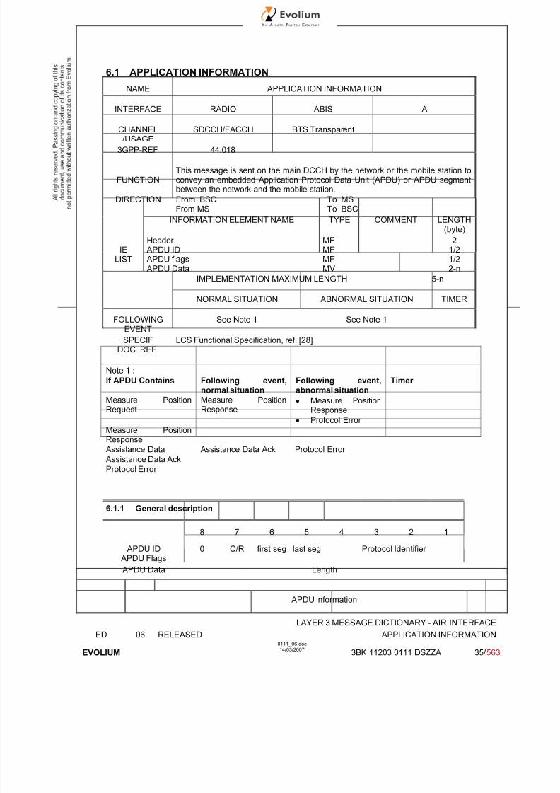
7/11/2019 1. Layer3 Air Interface Messages 0111_06
http://slidepdf.com/reader/full/1-layer3-air-interface-messages-011106 35/562
LAYER 3 MESSAGE DICTIONARY - AIR INTERFACE
ED 06 RELEASED APPLICATION INFORMATION
EVOLIUM
0111_06.doc14/03/2007
3BK 11203 0111 DSZZA 35/ 563
6.1 APPLICATION INFORMATION
NAME APPLICATION INFORMATION
INTERFACE RADIO ABIS A
CHANNEL/USAGE
SDCCH/FACCH BTS Transparent
3GPP-REF 44.018
FUNCTIONThis message is sent on the main DCCH by the network or the mobile station toconvey an embedded Application Protocol Data Unit (APDU) or APDU segmentbetween the network and the mobile station.
DIRECTION From BSCFrom MS
To MSTo BSC
INFORMATION ELEMENT NAME TYPE COMMENT LENGTH(byte)
IELIST
Header APDU IDAPDU flagsAPDU Data
MFMFMFMV
21/21/22-n
IMPLEMENTATION MAXIMUM LENGTH 5-n
NORMAL SITUATION ABNORMAL SITUATION TIMER
FOLLOWINGEVENT
See Note 1 See Note 1
SPECIFDOC. REF.
LCS Functional Specification, ref. [28]
Note 1 :
If APDU Contains Following event,normal situation
Following event,abnormal situation
Timer
Measure PositionRequest
Measure PositionResponse
• Measure PositionResponse
• Protocol Error
Measure PositionResponse
Assistance Data Assistance Data Ack Protocol Error
Assistance Data Ack
Protocol Error
6.1.1 General description
8 7 6 5 4 3 2 1
APDU IDAPDU Flags
0 C/R first seg last seg Protocol Identifier
APDU Data Length
APDU information

7/11/2019 1. Layer3 Air Interface Messages 0111_06
http://slidepdf.com/reader/full/1-layer3-air-interface-messages-011106 36/562
LAYER 3 MESSAGE DICTIONARY - AIR INTERFACE
ED 06 RELEASED APPLICATION INFORMATION
EVOLIUM
0111_06.doc14/03/2007
3BK 11203 0111 DSZZA 36/ 563
6.1.2 APDU ID
TYPE: M
DEFINITIONThe APDU ID information element identifies the particular protocol and associated application for anAPDU. It is a type 1 I.E.
BIT DESCRIPTION
8 7 6 5 4 3 2 1
APDU ID I.E.I Protocol Identifier octet1
SUB PARAMETER DEFINITION
Protocol identifier (octet 1)
Bits Protocol / Application4 3 2 10 0 0 0 RRLP (3GPP TS 04.31)/ LCS0 0 0 1to reserved for future use1 1 1 1
PARAMETER ORIGIN - ACTION ON PARAMETER
6.1.3 APDU Flags
TYPE: M
DEFINITIONThe APDU Flags information element provides segmentation and control information for an associatedAPDU. It is a type 1 I.E.
BIT DESCRIPTION
8 7 6 5 4 3 2 1
APDU ID I.E.I 0spare
C/R firstseg.
lastseg.
octet1
SUB PARAMETER DEFINITIONLast Segment (octet 1)bit 10 Last or only segment1 Not last or only segment
First Segment (octet 1)bit 20 First or only segment

7/11/2019 1. Layer3 Air Interface Messages 0111_06
http://slidepdf.com/reader/full/1-layer3-air-interface-messages-011106 37/562
LAYER 3 MESSAGE DICTIONARY - AIR INTERFACE
ED 06 RELEASED APPLICATION INFORMATION
EVOLIUM
0111_06.doc14/03/2007
3BK 11203 0111 DSZZA 37/ 563
1 Not first or only segment
C/R (octet 1)If last seg. = 0, then:bit 30 Command or Final Response1 Not Command or Final Response
If last seg. = 1, then bit 3 is spare and set to 0
Note : as shown in 6.1.1, the 4 bits are coded on bits 5 to 8, while the Protocol Identifier of APDU I.E.is coded on bits 1 to 4.
PARAMETER ORIGIN - ACTION ON PARAMETER
6.1.4 APDU Data
TYPE: M
DEFINITIONThe purpose of the information element is to provide an APDU or APDU segment.
BIT DESCRIPTIONThe APDU Data is a type 4 information element with minimum length of 1 octet (as it is a LV typeinformation element). No upper length limit is specified except for that given by the maximum number of octets in a L3 message (3GPP TS 04.06).
8 7 6 5 4 3 2 1
Length of APDU contents octet 1
APDU Information octet 2-n
APDU Information (octets 2-n)Contains an RRLP message as defined in 3GPP TS 04.31.
Note 1: Messages are segmented on octet boundaries. Zero bits are used, where necessary, topad out the last segment to an octet boundary.
PARAMETER ORIGIN - ACTION ON PARAMETER
The RRLP message may be one of the following messages :
• Measure Position Request
• Measure Position Response
• Assistance Data
• Assistance Data Ack
• Protocol Error
These messages are described in the following paragraphs.
6.1.4.1 Measure Position Request
This component is used by the SMLC to request location measurements or a location estimate fromthe MS. It includes QoS, other instructions, and possible assistance data to the MS.

7/11/2019 1. Layer3 Air Interface Messages 0111_06
http://slidepdf.com/reader/full/1-layer3-air-interface-messages-011106 38/562
LAYER 3 MESSAGE DICTIONARY - AIR INTERFACE
ED 06 RELEASED APPLICATION INFORMATION
EVOLIUM
0111_06.doc14/03/2007
3BK 11203 0111 DSZZA 38/ 563
The complete ASN.1 coding is not given below (see 3GPP TS 04.31 for details), a short description of the information elements is given.
Name Usage Type Comments
positionInstruct QoS related information (precisionrequirements, response time, radioenvironnement characterisation)
MANDATORY See possible valuesbelow
referenceAssistData information related to the BTSused for E-OTD OPTIONAL not used
msrAssistData information related to the BTSused for E-OTD
OPTIONAL not used
systemInfoAssistData information related to the BTSused for E-OTD
OPTIONAL not used
gps-AssistData GPS related information (time,satellites description …)
OPTIONAL
extensionContainer information related to E-OTD OPTIONAL not used
rel98-MsrPosition-Req-extension
information related to E-OTD OPTIONAL not used
positionInstruct values :
MethodType msAssistedmsBasedmsBasedPref msAssistedPref
PositionMethod e-OTD not usedGPSGPS or e-OTD not used
MeasureResponseTime value N = 0-7 inducing 2N
secondsuseMultipleSets multipleSets not used
OneSetThe optional information environmentCharacter is not sent by the Alcatel BSS.
6.1.4.2 Measure Position Response
This component is used by the MS to respond to a Measure Position Request from the SMLC withlocation measurements, a location estimate, or an error indication.The complete ASN.1 coding is not given below (see 3GPP TS 04.31 for details), a short description of the information elements is given.
Name Usage Type Comments
multipleSets usage of multiple sets OPTIONAL not used in currentversion of the protocol
referenceIdentity information related to the BTSused for E-OTD
OPTIONAL not used
otd-MeasureInfo information related to E-OTDmeasurements
OPTIONAL not used
locationInfo information related to GPSmeasurements
OPTIONAL
gps-MeasureInfo information related to GPSmeasurements
OPTIONAL
locationError Error codes in case of failure OPTIONAL See possible valuesbelow
extensionContainer OPTIONAL
rel-98-MsrPosition-Rsp-Extension
information related to E-OTDmeasurements
OPTIONAL not used
LocationInfo values :refFrame 0…65535gpsTOW 0..14399999
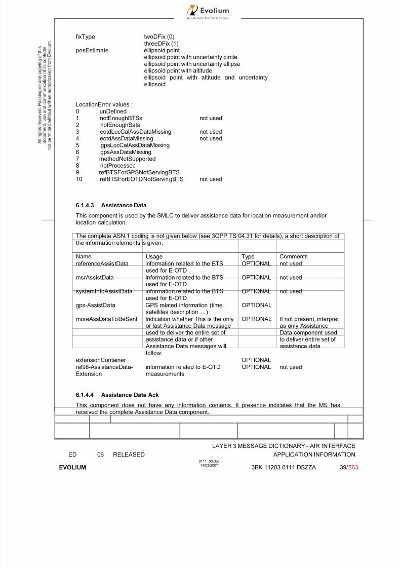
7/11/2019 1. Layer3 Air Interface Messages 0111_06
http://slidepdf.com/reader/full/1-layer3-air-interface-messages-011106 39/562
LAYER 3 MESSAGE DICTIONARY - AIR INTERFACE
ED 06 RELEASED APPLICATION INFORMATION
EVOLIUM
0111_06.doc14/03/2007
3BK 11203 0111 DSZZA 39/ 563
fixType twoDFix (0)threeDFix (1)
posEstimate ellipsoid pointellipsoid point with uncertainty circleellipsoid point with uncertainty ellipseellipsoid point with altitudeellipsoid point with altitude and uncertainty
ellipsoid
LocationError values :0 unDefined1 notEnoughBTSs not used2 notEnoughSats3 eotdLocCalAssDataMissing not used4 eotdAssDataMissing not used5 gpsLocCalAssDataMissing6 gpsAssDataMissing7 methodNotSupported8 notProcessed
9 refBTSForGPSNotServingBTS10 refBTSForEOTDNotServingBTS not used
6.1.4.3 Assistance Data
This component is used by the SMLC to deliver assistance data for location measurement and/or location calculation.
The complete ASN.1 coding is not given below (see 3GPP TS 04.31 for details), a short description of the information elements is given.
Name Usage Type Comments
referenceAssistData information related to the BTSused for E-OTD
OPTIONAL not used
msrAssistData information related to the BTSused for E-OTD
OPTIONAL not used
systemInfoAssistData information related to the BTSused for E-OTD
OPTIONAL not used
gps-AssistData GPS related information (time,satellites description …)
OPTIONAL
moreAssDataToBeSent Indication whether This is the onlyor last Assistance Data messageused to deliver the entire set of assistance data or if other Assistance Data messages willfollow.
OPTIONAL If not present, interpretas only AssistanceData component usedto deliver entire set of assistance data
extensionContainer OPTIONAL
rel98-AssistanceData-Extension
information related to E-OTDmeasurements
OPTIONAL not used
6.1.4.4 Assistance Data Ack
This component does not have any information contents. It presence indicates that the MS hasreceived the complete Assistance Data component.

7/11/2019 1. Layer3 Air Interface Messages 0111_06
http://slidepdf.com/reader/full/1-layer3-air-interface-messages-011106 40/562
LAYER 3 MESSAGE DICTIONARY - AIR INTERFACE
ED 06 RELEASED APPLICATION INFORMATION
EVOLIUM
0111_06.doc14/03/2007
3BK 11203 0111 DSZZA 40/ 563
6.1.4.5 Protocol Error
This component is used by the receiving entity (SMLC or MS) to indicate to the sending entity, thatthere is a problem that prevents the receiving entity to receive a complete and understandablecomponent.Note : this message is not sent by the SMLC in Alcatel first implementation.
-- Protocol Error component
ProtocolError ::= SEQUENCE {errorCause ErrorCodes,extensionContainer ExtensionContainer OPTIONAL,
...}
Following error codes are defined :0 unDefined1 missing Component2 incorrectData3 missingIEorComponentElement4 messageTooShort5 unknowReferenceNumber

7/11/2019 1. Layer3 Air Interface Messages 0111_06
http://slidepdf.com/reader/full/1-layer3-air-interface-messages-011106 41/562
LAYER 3 MESSAGE DICTIONARY - AIR INTERFACE
ED 06 RELEASED ASSIGNMENT COMMAND
EVOLIUM
0111_06.doc14/03/2007
3BK 11203 0111 DSZZA 41/ 563
6.2 ASSIGNMENT COMMAND
NAME ASSIGNMENT COMMAND
INTERFACE RADIO ABIS A
CHANNEL/USAGE
SDCCH/FACCH BTS Transparent
3GPP-REF 44.01844.018
FUNCTIONThis message is sent on the main DCCH from the BSC to the Mobile Station tochange the channel configuration to another independent dedicated channelconfiguration.
DIRECTION From BSC To MS
INFORMATION ELEMENT NAME TYPE COMMENT LENGTH(byte)
IELIST
Header
Description of the 1st Channel, after timePower CommandFrequency List, after timeCell Channel DescriptionDescription of the multislot configurationMode of the 1st Channel (Channel Set 1)Mode of Channel Set 2Mode of Channel Set 3Mode of Channel Set 4Mode of Channel Set 5Mode of Channel Set 6Mode of Channel Set 7Mode of Channel Set 8
Description of the 2nd Channel, after timeMode of the 2nd ChannelMobile Allocation, after timeStarting TimeFrequency List, before timeDescription of the 1st Chan., before timeDescription of the 2nd Chan., before timeFrequency Channel Seq. ,before timeMobile Allocation, before timeCipher Mode SettingVGCS target mode IndicationMultiRate configuration
M V M V C TLV O TV C TLV O TV O TV O TV O TV O TV O TV O TV O TV
O TV O TV C TLV O TV C TLV O TV O TV C TV C TLV O TV O TLV O TV
(1)(2)
(5)Not usedNot usedNot usedNot usedNot usedNot usedNot used
Not usedNot used(3)Not usedNot usedNot usedNot usedNot usedNot usedNot used(7)(6)
2
31
4-132*17
3-12*22*2*2*2*2*2*2*
42
3-103
4-132* 4* 4* 10*
3-10* 1*3*4-8
IMPLEMENTATION MAXIMUM LENGTH (4)
NORMAL SITUATION ABNORMAL SITUATION TIMER
FOLLOWINGEVENT
ASSIGNMENT COMPLETE ASSIGNMENT FAILURET3107
SPECIFDOC. REF.
Normal assignment procedure (ref. [3])Internal handover (ref. [6])

7/11/2019 1. Layer3 Air Interface Messages 0111_06
http://slidepdf.com/reader/full/1-layer3-air-interface-messages-011106 42/562
LAYER 3 MESSAGE DICTIONARY - AIR INTERFACE
ED 06 RELEASED ASSIGNMENT COMMAND
EVOLIUM
0111_06.doc14/03/2007
3BK 11203 0111 DSZZA 42/ 563
* New elements introduced in GSM Phase 2
(1) Used in the two following cases: i) Used for Phase 2 biband MS when the assigned channel ishopping in the P-GSM band or ii) used for any MS when the assigned channel is hopping in the E-GSM (and not in the P-GSM), GSM850, DCS1800 or DCS1900 band.
(2) Used for Phase 1 monoband P-GSM MS or for Phase 2 monoband P-GSM or for Phase 2
monoband E-GSM MS when the assigned channel is hopping in the P-GSM band.
(3) Used for Phase 1 monoband P-GSM MS or for Phase 2 monoband P-GSM or for Phase 2monoband E-GSM MS when the assigned channel is hopping in the P-GSM band.
(4) The length depends on the network category, the number max of frequencies in Frequency List(maximum 64 frequencies), and the MS type (See below table):
MS band capability Frequencyband of the
allocated radioresource
Max. length of theAssignment Command
message
Comments
PGSM P-GSM 43 With CA + MA
DCS1800 or DCS1800-GSM850 or DCS1800-GSM900 DCS1800 60 With Range_512
DCS1900 or DCS1900-GSM850 DCS1900 60 With Range_512
E-GSM, GSM850, GSM850-DCS1800,
or GSM850-DCS1900
GSM850 34 With variable bitmap
(5) This field is always included, although optional.
(6) This field is only included for calls established with AMR codec.
(7) This field is only included for the talker of a voice group call.

7/11/2019 1. Layer3 Air Interface Messages 0111_06
http://slidepdf.com/reader/full/1-layer3-air-interface-messages-011106 43/562
LAYER 3 MESSAGE DICTIONARY - AIR INTERFACE
ED 06 RELEASED ASSIGNMENT COMMAND
EVOLIUM
0111_06.doc14/03/2007
3BK 11203 0111 DSZZA 43/ 563
GENERAL DESCRIPTION
6.2.1.1 Assigned channel in the P-GSM band
6.2.1.1.1 Phase 1 monoband P-GSM MS
The assigned channel is assumed hopping on more than one frequency in the P-GSM band.
8 7 6 5 4 3 2 1
0 0 0 0 0 1 1 0
0 0 1 0 1 1 1 0
Channel type and TDMA offset TN
TSC H=1-> MAIO (high part)
Channel, H=0-> spare ARFCN (Hpart)
Description MAIO low part H S N
A R F C N (low part)
Power Command 0 0 0 Power level
0 1 1 0 0 0 1 0
Cell
0 0FORMAT-ID
0 0 124CA
ARFCN
123 122 121
ChannelDescription 120
CA ARFCN......................... 113
Optional17 octets
...........
CA ARFCN008 007 006 005 004 003 002 001
Channel0 1 1 0 0 0 1 1
Mode Mode Optional
0 1 1 1 0 0 1 0
MobileLength (value ≤8 )
Allocation MAC8n
MAC
8n-1
MAC
8n-7
Conditional3-10 octets
MAC8
MAC1

7/11/2019 1. Layer3 Air Interface Messages 0111_06
http://slidepdf.com/reader/full/1-layer3-air-interface-messages-011106 44/562
LAYER 3 MESSAGE DICTIONARY - AIR INTERFACE
ED 06 RELEASED ASSIGNMENT COMMAND
EVOLIUM
0111_06.doc14/03/2007
3BK 11203 0111 DSZZA 44/ 563
6.2.1.1.2 Phase 2 monoband P-GSM or E-GSM MS
The assigned channel is assumed hopping on more than one frequency in the P-GSM band.
8 7 6 5 4 3 2 1
0 0 0 0 0 1 1 0
0 0 1 0 1 1 1 0Channel type and TDMA offset TN
Description of the
TSC H=1-> MAIO (high part)
First Channel, H=0-> spare ARFCN (Hpart)
after time MAIO low part H S N
A R F C N (low part)
Power Command 0 0 0 Power level
0 1 1 0 0 0 1 0
Cell ChannelDescription
0 0FORMAT-ID
0 0 124CA
ARFCN
123 122 121
120CA ARFCN
......................... 113Optional17 octets
...........
CA ARFCN008 007 006 005 004 003 002 001
Description of the
0 0 0 1 0 0 0 0
multislot Length = 2
configuration 0ext
DA7
DA6
DA5
DA4
DA3
DA2
DA1
Optional
1ext
UA7
UA6
UA5
UA4
UA3
UA2
UA1
Mode of the FirstChannel
0 1 1 0 0 0 1 1
(Channel Set 1) Mode Optional
0 1 1 1 0 0 1 0
MobileAllocation,
Length (value ≤8 )
after time MAC8n
MAC
8n-1
MAC
8n-7
Conditional3-10 octets
MA
C8
MA
C1
VGCS target 0 0 0 0 0 0 0 1 Optional
mode Indication Length of VGCS target mode Indic. 3 octets
(Note 1) Target mode Group cipher key number 1spare
1spare
0 0 0 0 0 0 1
MultiRate Length (value ≤ 6) Optional
configuration MR version NSCB ICMI spare Start mode 4-8 octets
(Note 2) Parameters for MultiRate speech
Note 1: This field is only included for the talker of a voice group call.
Note 2: This field is only included for calls established with AMR codec.

7/11/2019 1. Layer3 Air Interface Messages 0111_06
http://slidepdf.com/reader/full/1-layer3-air-interface-messages-011106 45/562
LAYER 3 MESSAGE DICTIONARY - AIR INTERFACE
ED 06 RELEASED ASSIGNMENT COMMAND
EVOLIUM
0111_06.doc14/03/2007
3BK 11203 0111 DSZZA 45/ 563
6.2.1.1.3 Phase 2 biband MS
For phase 2 biband MS the "Frequency List, after time" is always used to assigned a channel hoppingon more than one frequency in the P-GSM band because it is the shortest way of coding frequencies,see section 6.2.1.2 for the description.
6.2.1.2 Assigned channel in the E-GSM, GSM850, DCS1800 or DCS1900 band
When the assigned channel is hopping on more than one frequency in the E-GSM, GSM850,DCS1800 or DCS1900 band, the Frequency List IE is used with Range 1024, range 512, range 256 or range 128 format:
8 7 6 5 4 3 2 1
0 0 0 0 0 1 1 0
0 0 1 0 1 1 1 0
Channel type and TDMA offset TN
Description of the TSC H=1-> MAIO (high part)
First Channel, after H=0-> spare ARFCN (Hpart)
time MAIO low part H S N
A R F C N (low part)
Power Command 0 0 0 Power level
0 0 0 0 0 1 0 1
Length of frequency list contents
Frequency List,after time
1 0FORMAT-ID
0 0 FORMAT-ID(continued)
Note 1
ORIG-ARFCN
high
ORIG-ARFCN (middle part) Optional
ORIG-ARFCN
(low)
W(1) (high part)
W(1)
(lowpart)
W(2) (high part)
W(2) to W(3) are on 8 bits, when present;W(4) to W(7) are on 7 bits, when present;W(8) to W(15) are on 6 bits, when present;W(16) to W(31) are on 5 bits, when present;W(32) to W(63) are on 4 bits, when present.
.. .. ..
Description of the 0 0 0 1 0 0 0 0
multislot Length = 2
configuration 0ext
DA7
DA6
DA5
DA4
DA3
DA2
DA1
Optional
1ext
UA7
UA6
UA5
UA4
UA3
UA2
UA1
Mode of the FirstChannel (Channel
0 1 1 0 0 0 1 1
Set 1) Mode
VGCS target 0 0 0 0 0 0 0 1 Optional
mode Indication Length of VGCS target mode Indic. 3 octets
Target mode Group cipher key number 1spare
1spare
0 0 0 0 0 0 1
MultiRateconfiguration
Length (value ≤ 6 ) Optional
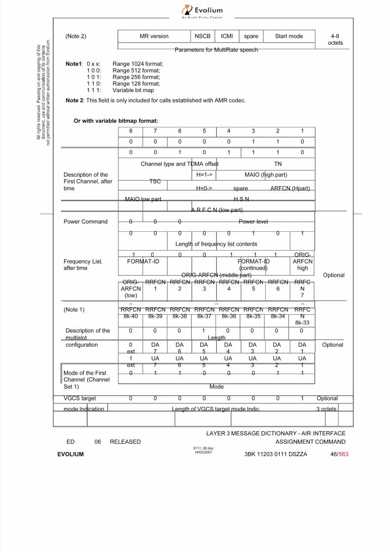
7/11/2019 1. Layer3 Air Interface Messages 0111_06
http://slidepdf.com/reader/full/1-layer3-air-interface-messages-011106 46/562
LAYER 3 MESSAGE DICTIONARY - AIR INTERFACE
ED 06 RELEASED ASSIGNMENT COMMAND
EVOLIUM
0111_06.doc14/03/2007
3BK 11203 0111 DSZZA 46/ 563
(Note 2) MR version NSCB ICMI spare Start mode 4-8octets
Parameters for MultiRate speech
Note1: 0 x x: Range 1024 format;1 0 0: Range 512 format;1 0 1: Range 256 format;
1 1 0: Range 128 format;1 1 1: Variable bit map
Note 2: This field is only included for calls established with AMR codec.
Or with variable bitmap format:
8 7 6 5 4 3 2 1
0 0 0 0 0 1 1 0
0 0 1 0 1 1 1 0
Channel type and TDMA offset TN
Description of theFirst Channel, after TSC
H=1-> MAIO (high part)
time H=0-> spare ARFCN (Hpart)
MAIO low part H S N
A R F C N (low part)
Power Command 0 0 0 Power level
0 0 0 0 0 1 0 1
Length of frequency list contents
Frequency List,after time
1 0FORMAT-ID
0 0 1 1 1FORMAT-ID(continued)
ORIG-ARFCN
high
ORIG-ARFCN (middle part) Optional
ORIG-ARFCN
(low)
RRFCN1
RRFCN2
RRFCN3
RRFCN4
RRFCN5
RRFCN6
RRFCN7
.. .. ..
(Note 1) RRFCN8k-40
RRFCN8k-39
RRFCN8k-38
RRFCN8k-37
RRFCN8k-36
RRFCN8k-35
RRFCN8k-34
RRFCN
8k-33
Description of the 0 0 0 1 0 0 0 0
multislot Lengthconfiguration 0ext
DA7
DA6
DA5
DA4
DA3
DA2
DA1
Optional
1ext
UA7
UA6
UA5
UA4
UA3
UA2
UA1
Mode of the FirstChannel (Channel
0 1 1 0 0 0 1 1
Set 1) Mode
VGCS target 0 0 0 0 0 0 0 1 Optional
mode Indication Length of VGCS target mode Indic. 3 octets
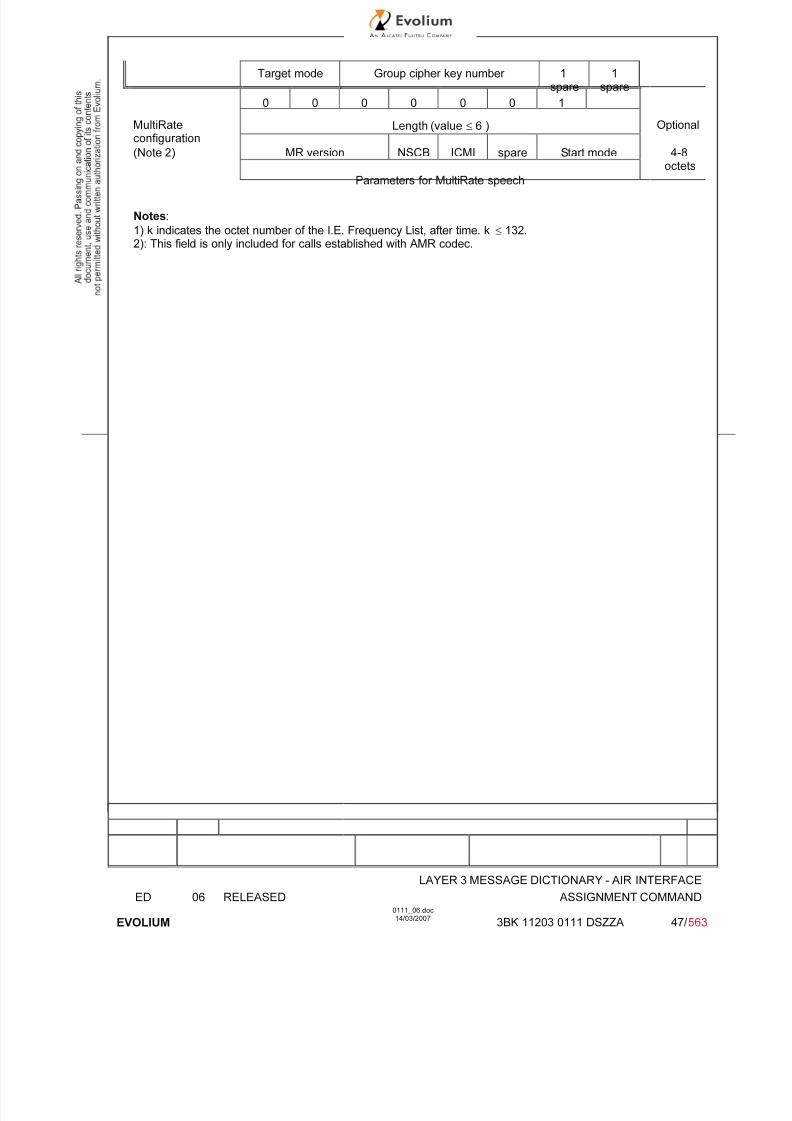
7/11/2019 1. Layer3 Air Interface Messages 0111_06
http://slidepdf.com/reader/full/1-layer3-air-interface-messages-011106 47/562
LAYER 3 MESSAGE DICTIONARY - AIR INTERFACE
ED 06 RELEASED ASSIGNMENT COMMAND
EVOLIUM
0111_06.doc14/03/2007
3BK 11203 0111 DSZZA 47/ 563
Target mode Group cipher key number 1spare
1spare
0 0 0 0 0 0 1
MultiRateconfiguration
Length (value ≤ 6 ) Optional
(Note 2) MR version NSCB ICMI spare Start mode 4-8octets
Parameters for MultiRate speech
Notes:
1) k indicates the octet number of the I.E. Frequency List, after time. k ≤ 132.2): This field is only included for calls established with AMR codec.
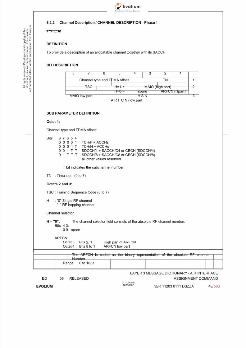
7/11/2019 1. Layer3 Air Interface Messages 0111_06
http://slidepdf.com/reader/full/1-layer3-air-interface-messages-011106 48/562
LAYER 3 MESSAGE DICTIONARY - AIR INTERFACE
ED 06 RELEASED ASSIGNMENT COMMAND
EVOLIUM
0111_06.doc14/03/2007
3BK 11203 0111 DSZZA 48/ 563
6.2.2 Channel Description / CHANNEL DESCRIPTION - Phase 1
TYPE: M
DEFINITION
To provide a description of an allocatable channel together with its SACCH.
BIT DESCRIPTION
8 7 6 5 4 3 2 1
Channel type and TDMA offset TN 1
TSC H=1-> MAIO (high part) 2
H=0-> spare ARFCN (Hpart)
MAIO low part H S N 3
A R F C N (low part)
SUB PARAMETER DEFINITION
Octet 1:
Channel type and TDMA offset:
Bits 8 7 6 5 40 0 0 0 1 TCH/F + ACCHs0 0 0 1 T TCH/H + ACCHs0 0 1 T T SDCCH/4 + SACCH/C4 or CBCH (SDCCH/4)0 1 T T T SDCCH/8 + SACCH/C8 or CBCH (SDCCH/8)
all other values reserved
T bit indicates the subchannel number.
TN : Time slot (0 to 7)
Octets 2 and 3:
TSC : Training Sequence Code (0 to 7)
H : "0" Single RF channel"1" RF hopping channel
Channel selector:
H = "0": The channel selector field consists of the absolute RF channel number.Bits 4 3:
0 0 spare
ARFCN:Octet 3 Bits 2, 1 High part of ARFCNOctet 4 Bits 8 to 1 ARFCN low part
The ARFCN is coded as the binary representation of the absolute RF channelNumber.
Range: 0 to 1023

7/11/2019 1. Layer3 Air Interface Messages 0111_06
http://slidepdf.com/reader/full/1-layer3-air-interface-messages-011106 49/562
LAYER 3 MESSAGE DICTIONARY - AIR INTERFACE
ED 06 RELEASED ASSIGNMENT COMMAND
EVOLIUM
0111_06.doc14/03/2007
3BK 11203 0111 DSZZA 49/ 563
H = "1": The channel selector field consists of the mobile allocation index offset, MAIO, and thehopping sequence number, HSN.
MAIO:Octet 3 Bits 4 to 1 high partOctet 4 Bits 8 to 7 low part
HSN (Octet 4, Bits 1 to 6):Value 0 to 63.The HSN field is coded as the binary representation of the hopping sequence number.
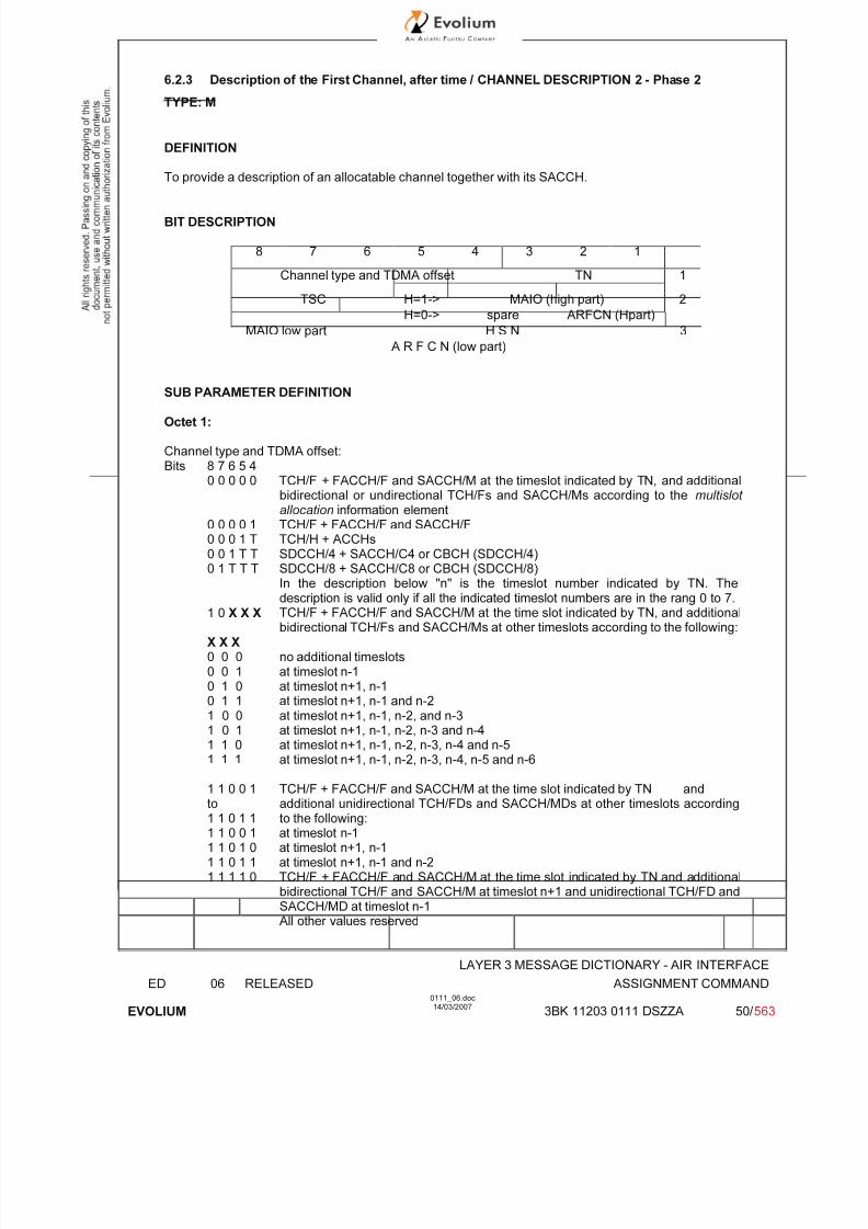
7/11/2019 1. Layer3 Air Interface Messages 0111_06
http://slidepdf.com/reader/full/1-layer3-air-interface-messages-011106 50/562
LAYER 3 MESSAGE DICTIONARY - AIR INTERFACE
ED 06 RELEASED ASSIGNMENT COMMAND
EVOLIUM
0111_06.doc14/03/2007
3BK 11203 0111 DSZZA 50/ 563
6.2.3 Description of the First Channel, after time / CHANNEL DESCRIPTION 2 - Phase 2
TYPE: M
DEFINITION
To provide a description of an allocatable channel together with its SACCH.
BIT DESCRIPTION
8 7 6 5 4 3 2 1
Channel type and TDMA offset TN 1
TSC H=1-> MAIO (high part) 2
H=0-> spare ARFCN (Hpart)
MAIO low part H S N 3
A R F C N (low part)
SUB PARAMETER DEFINITION
Octet 1:
Channel type and TDMA offset:Bits 8 7 6 5 4
0 0 0 0 0 TCH/F + FACCH/F and SACCH/M at the timeslot indicated by TN, and additionalbidirectional or undirectional TCH/Fs and SACCH/Ms according to the multislot allocation information element
0 0 0 0 1 TCH/F + FACCH/F and SACCH/F0 0 0 1 T TCH/H + ACCHs0 0 1 T T SDCCH/4 + SACCH/C4 or CBCH (SDCCH/4)
0 1 T T T SDCCH/8 + SACCH/C8 or CBCH (SDCCH/8)In the description below "n" is the timeslot number indicated by TN. Thedescription is valid only if all the indicated timeslot numbers are in the rang 0 to 7.
1 0 X X X TCH/F + FACCH/F and SACCH/M at the time slot indicated by TN, and additionalbidirectional TCH/Fs and SACCH/Ms at other timeslots according to the following:
X X X 0 0 0 no additional timeslots0 0 1 at timeslot n-10 1 0 at timeslot n+1, n-10 1 1 at timeslot n+1, n-1 and n-21 0 0 at timeslot n+1, n-1, n-2, and n-31 0 1 at timeslot n+1, n-1, n-2, n-3 and n-41 1 0 at timeslot n+1, n-1, n-2, n-3, n-4 and n-5
1 1 1 at timeslot n+1, n-1, n-2, n-3, n-4, n-5 and n-6
1 1 0 0 1to1 1 0 1 1
TCH/F + FACCH/F and SACCH/M at the time slot indicated by TN andadditional unidirectional TCH/FDs and SACCH/MDs at other timeslots accordingto the following:
1 1 0 0 1 at timeslot n-11 1 0 1 0 at timeslot n+1, n-11 1 0 1 1 at timeslot n+1, n-1 and n-21 1 1 1 0 TCH/F + FACCH/F and SACCH/M at the time slot indicated by TN and additional
bidirectional TCH/F and SACCH/M at timeslot n+1 and unidirectional TCH/FD andSACCH/MD at timeslot n-1All other values reserved
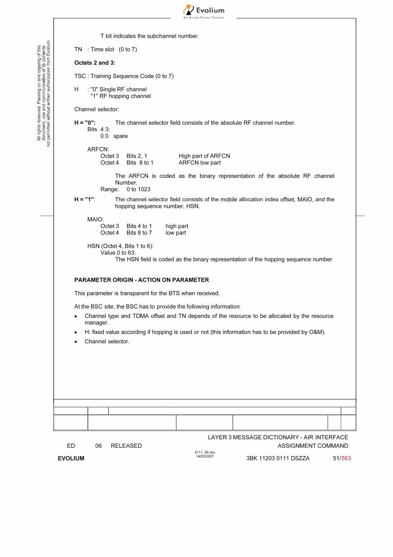
7/11/2019 1. Layer3 Air Interface Messages 0111_06
http://slidepdf.com/reader/full/1-layer3-air-interface-messages-011106 51/562
LAYER 3 MESSAGE DICTIONARY - AIR INTERFACE
ED 06 RELEASED ASSIGNMENT COMMAND
EVOLIUM
0111_06.doc14/03/2007
3BK 11203 0111 DSZZA 51/ 563
T bit indicates the subchannel number.
TN : Time slot (0 to 7)
Octets 2 and 3:
TSC : Training Sequence Code (0 to 7)
H : "0" Single RF channel"1" RF hopping channel
Channel selector:
H = "0": The channel selector field consists of the absolute RF channel number.Bits 4 3:
0 0 spare
ARFCN:Octet 3 Bits 2, 1 High part of ARFCNOctet 4 Bits 8 to 1 ARFCN low part
The ARFCN is coded as the binary representation of the absolute RF channelNumber.
Range: 0 to 1023
H = "1": The channel selector field consists of the mobile allocation index offset, MAIO, and thehopping sequence number, HSN.
MAIO:Octet 3 Bits 4 to 1 high partOctet 4 Bits 8 to 7 low part
HSN (Octet 4, Bits 1 to 6):Value 0 to 63.
The HSN field is coded as the binary representation of the hopping sequence number.
PARAMETER ORIGIN - ACTION ON PARAMETER
This parameter is transparent for the BTS when received.
At the BSC site, the BSC has to provide the following information:
• Channel type and TDMA offset and TN depends of the resource to be allocated by the resourcemanager.
• H: fixed value according if hopping is used or not (this information has to be provided by O&M).
• Channel selector.

7/11/2019 1. Layer3 Air Interface Messages 0111_06
http://slidepdf.com/reader/full/1-layer3-air-interface-messages-011106 52/562
LAYER 3 MESSAGE DICTIONARY - AIR INTERFACE
ED 06 RELEASED ASSIGNMENT COMMAND
EVOLIUM
0111_06.doc14/03/2007
3BK 11203 0111 DSZZA 52/ 563
6.2.4 POWER COMMAND
TYPE: M
DEFINITION To provide the power level for the Mobile Station.
BIT DESCRIPTION
8 7 6 5 4 3 2 1
1 0 0 0 Power level
Bits 6 to 8 of octet 1 are spare bits (coded as 0).
SUB PARAMETER DEFINITION
Power level: binary representation of the power control level(0 to 31)
GSM phase 1
Power Controllevel GSM-900 DCS-1800
Peak power Binary value Peak power Binary value
0 43 dBm 0 30 dBm 0
1 41 dBm 1 28 dBm 1
2 39 dBm 2 26 dBm 2
3 37 dBm 3 24 dBm 3
4 35 dBm 4 22 dBm 4
5 33 dBm 5 20 dBm 5
6 31 dBm 6 18 dBm 6
7 29 dBm 7 16 dBm 7
8 27 dBm 8 14 dBm 89 25 dBm 9 12 dBm 9
10 23 dBm 10 10 dBm 10
11 21 dBm 11 8 dBm 11 (note 1)
12 19 dBm 12 6 dBm 12 (note 1)
13 17 dBm 13 4 dBm 13 (note 1)
14 15 dBm 14
15 13 dBm 15

7/11/2019 1. Layer3 Air Interface Messages 0111_06
http://slidepdf.com/reader/full/1-layer3-air-interface-messages-011106 53/562
LAYER 3 MESSAGE DICTIONARY - AIR INTERFACE
ED 06 RELEASED ASSIGNMENT COMMAND
EVOLIUM
0111_06.doc14/03/2007
3BK 11203 0111 DSZZA 53/ 563
GSM phase 2
Power Control
level GSM-900 DCS-1800 GSM-850
Peak power Binary value Peak power Binary value Peak Power Binary value
0 - - 30 dBm 0 - -
1 - - 28 dBm 1 - -2 39 dBm 2 26 dBm 2 39 dBm 2
3 37 dBm 3 24 dBm 3 37 dBm 3
4 35 dBm 4 22 dBm 4 35 dBm 4
5 33 dBm 5 20 dBm 5 33 dBm 5
6 31 dBm 6 18 dBm 6 31 dBm 6
7 29 dBm 7 16 dBm 7 29 dBm 7
8 27 dBm 8 14 dBm 8 27 dBm 8
9 25 dBm 9 12 dBm 9 25 dBm 9
10 23 dBm 10 10 dBm 10 23 dBm 10
11 21 dBm 11 8 dBm 11 21 dBm 11
12 19 dBm 12 6 dBm 12 19 dBm 12
13 17 dBm 13 4 dBm 13 17 dBm 1314 15 dBm 14 2 dBm 14 15 dBm 14
15 13 dBm 15 0 dBm 15 13 dBm 15
16 11 dBm 16 11 dBm 1617 9 dBm 17 9 dBm 1718 7 dBm 18 7 dBm 1819 5 dBm 19 5 dBm 19
Power Control
level
DCS-1900
Peak power
30 33dBm
31 32dBm
0 30dBm
1 28dBm
2 26 dBm
3 24 dBm
4 22 dBm
5 20 dBm
6 18 dBm
7 16 dBm
8 14 dBm
9 12 dBm
10 10 dBm
11 08 dBm
12 06 dBm13 04 dBm
14 02 dBm
15 0 dBm
Note 1: These power control levels are not authorised for MS DCS-1800 class 1. They are only usedby the MS class 2.
PARAMETER ORIGIN - ACTION ON PARAMETER
The parameter is transparent for the BTS. At the BSC site, this parameter is given to the MobileStation according to the classmark information received from the MS.
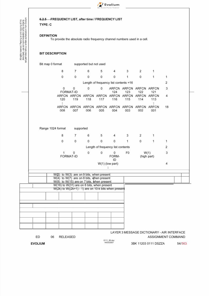
7/11/2019 1. Layer3 Air Interface Messages 0111_06
http://slidepdf.com/reader/full/1-layer3-air-interface-messages-011106 54/562
LAYER 3 MESSAGE DICTIONARY - AIR INTERFACE
ED 06 RELEASED ASSIGNMENT COMMAND
EVOLIUM
0111_06.doc14/03/2007
3BK 11203 0111 DSZZA 54/ 563
6.2.5 FREQUENCY LIST, after time / FREQUENCY LIST
TYPE: C
DEFINITIONTo provide the absolute radio frequency channel numbers used in a cell.
BIT DESCRIPTION
Bit map 0 format supported but not used
8 7 6 5 4 3 2 1
0 0 0 0 0 1 0 1 1
Length of frequency list contents =16 2
0 0
FORMAT-ID
0 0 ARFCN
124
ARFCN
123
ARFCN
122
ARFCN
121
3
ARFCN120
ARFCN119
ARFCN118
ARFCN117
ARFCN116
ARFCN115
ARFCN114
ARFCN113
4
: :
ARFCN008
ARFCN007
ARFCN006
ARFCN005
ARFCN004
ARFCN003
ARFCN002
ARFCN001
18
Range 1024 format supported
8 7 6 5 4 3 2 10 0 0 0 0 1 0 1 1
Length of frequency list contents 2
1 0FORMAT-ID
0 0 0FORM-
ID
F0 W(1)(high part)
3
W(1) (low part) 4
:
W(2) to W(3) are on 9 bits, when presentW(4) to W(7) are on 8 bits, when present
W(8) to W(15) are on 7 bits, when presentW(16) to W(31) are on 6 bits, when presentW(2k) to W((2k+1) - 1) are on 10-k bits when present

7/11/2019 1. Layer3 Air Interface Messages 0111_06
http://slidepdf.com/reader/full/1-layer3-air-interface-messages-011106 55/562
LAYER 3 MESSAGE DICTIONARY - AIR INTERFACE
ED 06 RELEASED ASSIGNMENT COMMAND
EVOLIUM
0111_06.doc14/03/2007
3BK 11203 0111 DSZZA 55/ 563
Range 512 format supported
8 7 6 5 4 3 2 1
0 0 0 0 0 1 0 1 1
Length of frequency list contents 2
1 0FORMAT-ID
0 0 1 0 0FORMAT-ID(continued)
ORIG-ARFCN
3
ORIG-ARFCN (middle part) 4
ORIG-ARFCN
(low)
W(1) (high part) 5
W(1) (low part) W(2) (high part) 6
:W(2) to W(3) are on 8 bits, when presentW(4) to W(7) are on 7 bits, when presentW(8) to W(15) are on 6 bits, when present
W(16) to W(31) are on 5 bits, when presentW(2k) to W((2k+1) - 1) are on 9-k bits when present
Range 256 format supported
8 7 6 5 4 3 2 1
0 0 0 0 0 1 0 1 1
Length of frequency list contents 2
1 0FORMAT-ID
0 0 1 0 1FORMAT-ID(continued)
ORIG-ARFCN
3
ORIG-ARFCN (middle part) 4
ORIG-ARFCN
(low)
W(1) (high part) 5
W(1)(low)
W(2) 6
:
W(2) to W(3) are on 7 bits, when presentW(4) to W(7) are on 6 bits, when present
W(8) to W(15) are on 5 bits, when presentW(16) to W(31) are on 4 bits, when presentW(2k) to W((2k+1) - 1) are on 8-k bits when present

7/11/2019 1. Layer3 Air Interface Messages 0111_06
http://slidepdf.com/reader/full/1-layer3-air-interface-messages-011106 56/562
LAYER 3 MESSAGE DICTIONARY - AIR INTERFACE
ED 06 RELEASED ASSIGNMENT COMMAND
EVOLIUM
0111_06.doc14/03/2007
3BK 11203 0111 DSZZA 56/ 563
Range 128 format supported
8 7 6 5 4 3 2 1
0 0 0 0 0 1 0 1 1
Length of frequency list contents 2
1 0FORMAT-ID
0 0 1 1 0FORMAT-ID(continued)
ORIG-ARFCN
3
ORIG-ARFCN (middle part) 4
ORIG-ARFCN
(low)
W(1) 5
:W(2) to W(3) are on 6 bits, when presentW(4) to W(7) are on 5 bits, when presentW(8) to W(15) are on 4 bits, when presentW(16) to W(31) are on 3 bits, when presentW(2k) to W((2k+1) - 1) are on 7-k bits when present
Variable bit map format supported
8 7 6 5 4 3 2 1
0 0 0 0 0 1 0 1 1
Length of frequency list contents =16 2
1 0FORMAT-ID
0 0 1 1 1FORMAT-ID(continued)
ORIG-ARFCN
high
3
ORIG-ARFCN (middle part) 4
ORIG-
ARFCN(low)
RRFCN
1
RRFCN
2
RRFCN
3
RRFCN
4
RRFCN
5
RRFCN
6
RRFCN
7
5
: :
RRFCN104
RRFCN105
RRFCN106
RRFCN107
RRFCN108
RRFCN109
RRFCN110
RRFCN111
18
SUB PARAMETER DEFINITION
Bits 5 and 6 are spare bits in octet 3.
FORMAT-ID : Format identifier.
F0 : Frequency 0 indicator. Coded 0 if ARFCN 0 is not a member of the set. Coded 1 if ARFCN 0 is a member of the set.
ORIG-ARFCN : This field encodes the ARFCN of one frequency belonging to the set. This value isalso used as the origin of the bit map to generate all the other frequencies.
RRFCN N : Relative Radio Frequency Channel Number N.- For an RF channel with ARFCN = (ORIG-ARFCN + N) mod 1024 belonging to the set,
then RRFCN N bit is coded as '1'.- For an RF channel with ARFCN = (ORIG-ARFCN + N) mod 1024 not belonging to the set,
then RRFCN N bit is coded as '0'.
W : Each non null W(k) allows to compute, together with some previous W(i) the ARFCNF(k) of a frequency in the set (see 3GPP TS 44.01844.018 for computation formulas).

7/11/2019 1. Layer3 Air Interface Messages 0111_06
http://slidepdf.com/reader/full/1-layer3-air-interface-messages-011106 57/562
LAYER 3 MESSAGE DICTIONARY - AIR INTERFACE
ED 06 RELEASED ASSIGNMENT COMMAND
EVOLIUM
0111_06.doc14/03/2007
3BK 11203 0111 DSZZA 57/ 563
PARAMETER ORIGIN - ACTION ON PARAMETER
ORIG-ARFCN, RRFCN N: Values stored in BSC and updated according to system reconfigurations.
6.2.6 CELL CHANNEL DESCRIPTION
TYPE: O
DEFINITION
To provide the reference frequency list to be used to decode the mobile allocation informationelement.
BIT DESCRIPTION
Bitmap 0 format
8 7 6 5 4 3 2 1
0 1 1 0 0 0 1 0 1
0 0 0 0 CA ARFCN 2
FORMAT-ID 124 123 122 121
120CA ARFCN
......................... 1133
...........
CA ARFCN 17008 007 006 005 004 003 002 001
Bits 5 and 6 are spare bits in octet 2.
SUB PARAMETER DEFINITION
FORMAT-ID : Format identifier Only bitmap 0 Format is supported.
CA ARFCN N : Cell Allocation Absolute Radio Frequency Channel Number N
CA ARFCN N : "0" not belonging to the cell allocation"1" belonging to the cell allocation
PARAMETER ORIGIN - ACTION ON PARAMETER
Format-ID : Fixed value = 00.
CA ARFCN N : Value stored in BSC and updated according to system reconfigurations.
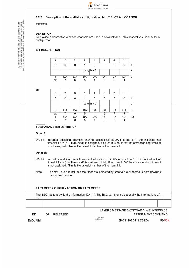
7/11/2019 1. Layer3 Air Interface Messages 0111_06
http://slidepdf.com/reader/full/1-layer3-air-interface-messages-011106 58/562
LAYER 3 MESSAGE DICTIONARY - AIR INTERFACE
ED 06 RELEASED ASSIGNMENT COMMAND
EVOLIUM
0111_06.doc14/03/2007
3BK 11203 0111 DSZZA 58/ 563
6.2.7 Description of the multislot configuration / MULTISLOT ALLOCATION
TYPE: C
DEFINITIONTo provide a description of which channels are used in downlink and uplink respectively, in a multislot
configuration.
BIT DESCRIPTION
8 7 6 5 4 3 2 1
0 0 0 1 0 0 0 0 1
Length = 1 2
1ext
DA7
DA6
DA5
DA4
DA3
DA2
DA1
3
Or 8 7 6 5 4 3 2 1
0 0 0 1 0 0 0 0 1
Length = 2 2
0ext
DA7
DA6
DA5
DA4
DA3
DA2
DA1
3
1ext
UA7
UA6
UA5
UA4
UA3
UA2
UA1
3a
SUB PARAMETER DEFINITION
Octet 3
DA 1-7: Indicates additional downlink channel allocation.If bit DA n is set to "1" this indicates thattimeslot TN = (n + TNm)mod8 is assigned. If bit DA n is set to "0" the corresponding timeslotis not assigned. TNm is the timeslot number of the main link.
Octet 3a
UA 1-7: Indicates additional uplink channel allocation.If bit UA n is set to "1" this indicates thattimeslot TN = (n + TNm)mod8 is assigned. If bit UA n is set to "0" the corresponding timeslot
is not assigned. TNm is the timeslot number of the main link.
Note: If octet 3a is not included the timeslots indicated by octet 3 are allocated in both downlinkand uplink direction
PARAMETER ORIGIN - ACTION ON PARAMETER
The BSC has to provide the information: DA 1-7. The BSC can provide optionally the information: UA1-7.
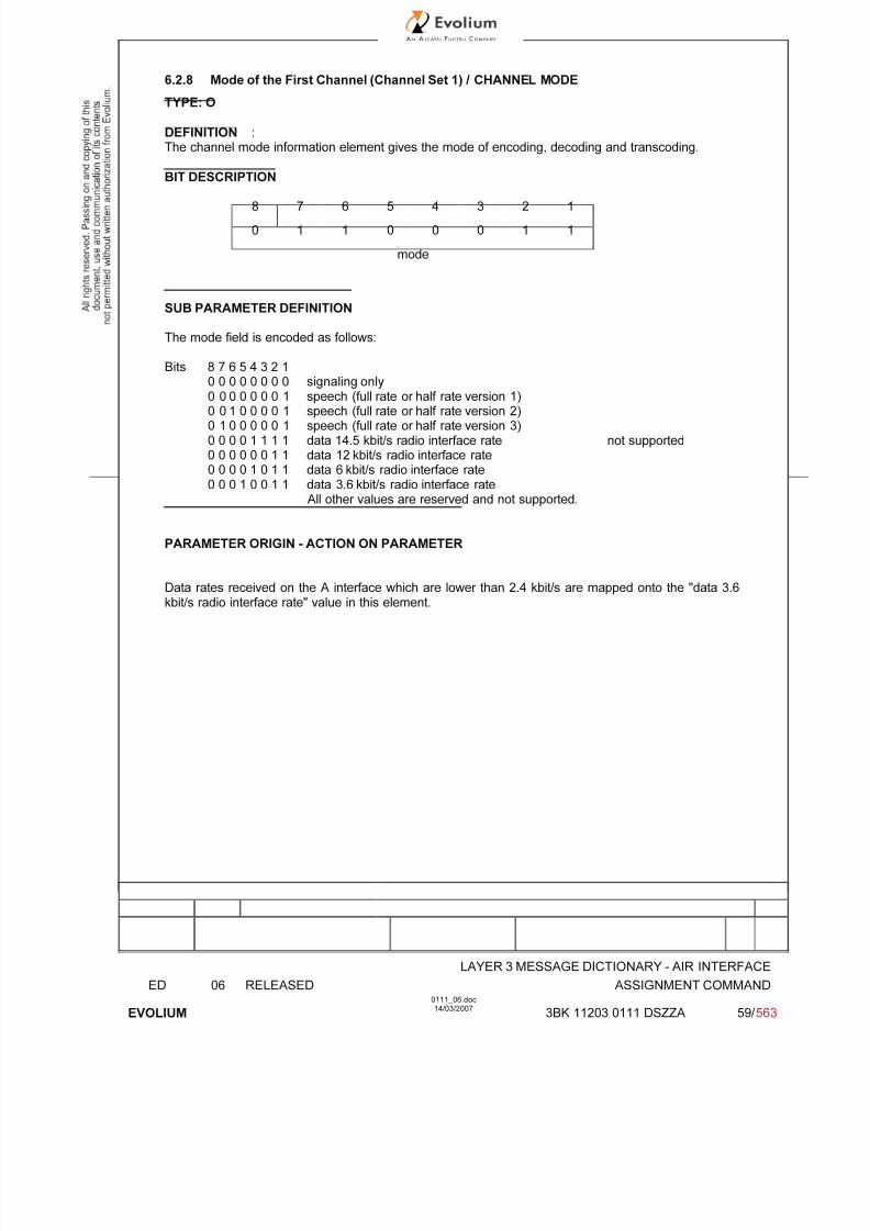
7/11/2019 1. Layer3 Air Interface Messages 0111_06
http://slidepdf.com/reader/full/1-layer3-air-interface-messages-011106 59/562
LAYER 3 MESSAGE DICTIONARY - AIR INTERFACE
ED 06 RELEASED ASSIGNMENT COMMAND
EVOLIUM
0111_06.doc14/03/2007
3BK 11203 0111 DSZZA 59/ 563
6.2.8 Mode of the First Channel (Channel Set 1) / CHANNEL MODE
TYPE: O
DEFINITION :The channel mode information element gives the mode of encoding, decoding and transcoding.
BIT DESCRIPTION
8 7 6 5 4 3 2 1
0 1 1 0 0 0 1 1
mode
SUB PARAMETER DEFINITION
The mode field is encoded as follows:
Bits 8 7 6 5 4 3 2 1
0 0 0 0 0 0 0 0 signaling only0 0 0 0 0 0 0 1 speech (full rate or half rate version 1)0 0 1 0 0 0 0 1 speech (full rate or half rate version 2)0 1 0 0 0 0 0 1 speech (full rate or half rate version 3)0 0 0 0 1 1 1 1 data 14.5 kbit/s radio interface rate not supported0 0 0 0 0 0 1 1 data 12 kbit/s radio interface rate0 0 0 0 1 0 1 1 data 6 kbit/s radio interface rate0 0 0 1 0 0 1 1 data 3.6 kbit/s radio interface rate
All other values are reserved and not supported.
PARAMETER ORIGIN - ACTION ON PARAMETER
Data rates received on the A interface which are lower than 2.4 kbit/s are mapped onto the "data 3.6kbit/s radio interface rate" value in this element.

7/11/2019 1. Layer3 Air Interface Messages 0111_06
http://slidepdf.com/reader/full/1-layer3-air-interface-messages-011106 60/562
LAYER 3 MESSAGE DICTIONARY - AIR INTERFACE
ED 06 RELEASED ASSIGNMENT COMMAND
EVOLIUM
0111_06.doc14/03/2007
3BK 11203 0111 DSZZA 60/ 563
6.2.9 MOBILE ALLOCATION, after time / MOBILE ALLOCATION
TYPE C
DEFINITION
To provide the part of the RF channels belonging to the cell allocation which is used in the MobileStation hopping sequence (primary band in GSM900).
BIT DESCRIPTION
8 7 6 5 4 3 2 1
0 1 1 1 0 0 1 0
length of Mobile allocation contents
(value ≤ 8 )
MAC8n
MAC
8n-1
MAC
8n-7
: :
MAC
008
MAC
001
SUB PARAMETER DEFINITION
MA length depends on the relative frequency span of the frequencies in the cell allocation frequencylist
MA Ci:Mobile Allocation RF Channel i - the RF channels represented in the MA C i bit fields are those which
in the "Cell Channel Description" information element are coded with "1" in the CA ARFCN N bit fields.
MA Ci = CA ARFCN N(i) i = 1,2...NF
(NF = Number of Frequencies in the CA frequency list).
For a RF channel belonging to the Mobile Allocation the MA C i bit is coded with a "1", for a RF
channel not belonging to the Mobile Allocation, the MA C i bit is coded with a "0". If NF mod 8 ≠ 0 thenbits NF to 8n in octet 3 must be coded with a "0" in each.
PARAMETER ORIGIN - ACTION ON PARAMETER
The parameter is transparent for the BTS when received from the BSC.
At the BSC site the following actions have to be performed
Mobile Allocation Stored and Updated during system reconfiguration.
6.2.10 VGCS target mode Indication

7/11/2019 1. Layer3 Air Interface Messages 0111_06
http://slidepdf.com/reader/full/1-layer3-air-interface-messages-011106 61/562
LAYER 3 MESSAGE DICTIONARY - AIR INTERFACE
ED 06 RELEASED ASSIGNMENT COMMAND
EVOLIUM
0111_06.doc14/03/2007
3BK 11203 0111 DSZZA 61/ 563
TYPE: O
DEFINITION :This IE indicates which mode is to be used on the new channel (i.e. dedicated mode or group transmitmode). If this information element is not present, the mode shall be the same as on the previouschannel.The “VGCS target mode Indication” OIE in the ASSIGNMENT COMMAND message sent for the (first
or subsequent) talker, is always valued as “group transmit mode”.The IE also indicates the group cipher key number for the group cipher key to be used on the newchannel or if the new channel is non ciphered. If the information element is not present, the cipheringmode shall be the same as on the previous channel.
BIT DESCRIPTION
8 7 6 5 4 3 2 1
VGCS target mode Indic. IEI octet 1
Length of VGCS target mode Indic. octet 2
Target mode Group cipher key number 1spare
1spare
octet 3
SUB PARAMETER DEFINITION
Target mode
Bit8 70 0 dedicated mode (not used)0 1 group transmit modeOther values are reserved for future use.
Group cipher key number
Bit6 5 4 30 0 0 0 no ciphering0 0 0 1 cipher key number 1 (not used)0 0 1 0 cipher key number 2 (not used)0 0 1 1 cipher key number 3 (not used)0 1 0 0 cipher key number 4 (not used)0 1 0 1 cipher key number 5 (not used)0 1 1 0 cipher key number 6 (not used)0 1 1 1 cipher key number 7 (not used)1 0 0 0 cipher key number 8 (not used)1 0 0 1 cipher key number 9 (not used)1 0 1 0 cipher key number A (not used)
1 0 1 1 cipher key number B (not used)1 1 0 0 cipher key number C (not used)1 1 0 1 cipher key number D (not used)1 1 1 0 cipher key number E (not used)1 1 1 1 cipher key number F (not used)
PARAMETER ORIGIN - ACTION ON PARAMETER

7/11/2019 1. Layer3 Air Interface Messages 0111_06
http://slidepdf.com/reader/full/1-layer3-air-interface-messages-011106 62/562
LAYER 3 MESSAGE DICTIONARY - AIR INTERFACE
ED 06 RELEASED ASSIGNMENT COMMAND
EVOLIUM
0111_06.doc14/03/2007
3BK 11203 0111 DSZZA 62/ 563
6.2.11 MULTIRATE CONFIGURATION
TYPE: O
DEFINITION :The MultiRate configuration information element gives all parameters related to a MultiRate speechcodec.
BIT DESCRIPTION
8 7 6 5 4 3 2 1
0 0 0 0 0 0 1 1 octet 1
Lengthoctet 2
MR version NSCB ICMI spare Start mode octet 3
Parameters for MultiRate speech octet 4
.
.
octet n (n ≤ 8)
SUB PARAMETER DEFINITION
Octet 3MR version (MultiRate speech version):Bits 8 7 6
0 0 1 Adaptive MultiRate speech version 1all other values are reserved.
NSCB (Noise Suppression Control Bit):Bit 5
0 Noise Suppression can be used (default)1 Noise Suppression shall be turned off
ICMI (Initial Codec Mode Indicator):Bit 4
0 The initial codec mode is defined by the implicit rule provided in 3GPP TS 05.091 The initial codec mode is defined by the Start Mode field
Bit 30 Spare
Start Mode:Bits 2 1
x x The initial codec mode is coded as in 3GPP TS 05.09 section 3.4.1

7/11/2019 1. Layer3 Air Interface Messages 0111_06
http://slidepdf.com/reader/full/1-layer3-air-interface-messages-011106 63/562
LAYER 3 MESSAGE DICTIONARY - AIR INTERFACE
ED 06 RELEASED ASSIGNMENT COMMAND
EVOLIUM
0111_06.doc14/03/2007
3BK 11203 0111 DSZZA 63/ 563
Parameters for MultiRate speech (octet 4 to octet n, n ≤ 8):
1) Parameters for MultiRate speech field for the MR version 1 when a set with one codec mode ischosen
8 7 6 5 4 3 2 1
Set of AMR codec modes octet 4
2) Parameters for MultiRate speech field for the MR version 1 when a set with two codec modes ischosen
8 7 6 5 4 3 2 1
Set of AMR codec modes octet 4
Spare0 0 Threshold 1 octet 5
SpareHysteresis 1 0 0 0 0 octet 6
3) Parameters for MultiRate speech field for the MR version 1 when a set of three codec modes ischosen
8 7 6 5 4 3 2 1
Set of AMR codec modes octet 4
Spare0 0 Threshold 1 octet 5
Hysteresis 1 Threshold 2 octet 6
Threshold Spare2 (cont.) Hysteresis 2 0 0 octet 7
4) Parameters for MultiRate speech field for the MR version 1 when a set of four modes is chosen
8 7 6 5 4 3 2 1
Set of AMR codec modes octet 4
Spare0 0 Threshold 1 octet 5
Hysteresis 1 Threshold 2 octet 6
Threshold Threshold 3
2 (cont.) Hysteresis 2 octet 7
Threshold (3) Hysteresis 3 octet 8
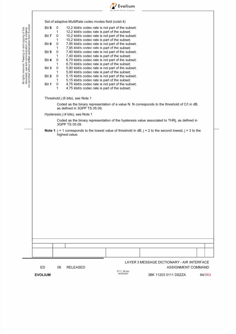
7/11/2019 1. Layer3 Air Interface Messages 0111_06
http://slidepdf.com/reader/full/1-layer3-air-interface-messages-011106 64/562
LAYER 3 MESSAGE DICTIONARY - AIR INTERFACE
ED 06 RELEASED ASSIGNMENT COMMAND
EVOLIUM
0111_06.doc14/03/2007
3BK 11203 0111 DSZZA 64/ 563
Set of adaptive MultiRate codec modes field (octet 4)
Bit 8 0 12,2 kbit/s codec rate is not part of the subset;1 12,2 kbit/s codec rate is part of the subset;
Bit 7 0 10,2 kbit/s codec rate is not part of the subset;1 10,2 kbit/s codec rate is part of the subset;
Bit 6 0 7,95 kbit/s codec rate is not part of the subset;1 7,95 kbit/s codec rate is part of the subset;
Bit 5 0 7,40 kbit/s codec rate is not part of the subset;1 7,40 kbit/s codec rate is part of the subset;
Bit 4 0 6,70 kbit/s codec rate is not part of the subset;1 6,70 kbit/s codec rate is part of the subset;
Bit 3 0 5,90 kbit/s codec rate is not part of the subset;
1 5,90 kbit/s codec rate is part of the subset;Bit 2 0 5,15 kbit/s codec rate is not part of the subset;
1 5,15 kbit/s codec rate is part of the subset;Bit 1 0 4,75 kbit/s codec rate is not part of the subset;
1 4,75 kbit/s codec rate is part of the subset;
Threshold j (6 bits), see Note 1
Coded as the binary representation of a value N. N corresponds to the threshold of C/I in dB,as defined in 3GPP TS 05.09;
Hysteresis j (4 bits), see Note 1
Coded as the binary representation of the hysteresis value associated to THRj, as defined in3GPP TS 05.09.
Note 1: j = 1 corresponds to the lowest value of threshold in dB, j = 2 to the second lowest, j = 3 to thehighest value.
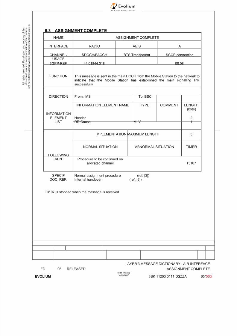
7/11/2019 1. Layer3 Air Interface Messages 0111_06
http://slidepdf.com/reader/full/1-layer3-air-interface-messages-011106 65/562
LAYER 3 MESSAGE DICTIONARY - AIR INTERFACE
ED 06 RELEASED ASSIGNMENT COMPLETE
EVOLIUM
0111_06.doc14/03/2007
3BK 11203 0111 DSZZA 65/ 563
6.3 ASSIGNMENT COMPLETE
NAME ASSIGNMENT COMPLETE
INTERFACE RADIO ABIS A
CHANNEL/ USAGE
SDCCH/FACCH BTS Transparent SCCP connection
3GPP-REF 44.01844.018 08.08
FUNCTION This message is sent in the main DCCH from the Mobile Station to the network toindicate that the Mobile Station has established the main signalling linksuccessfully.
DIRECTION From: MS To: BSC
INFORMATION ELEMENT NAME TYPE COMMENT LENGTH(byte)
INFORMATIONELEMENT
LISTHeader RR Cause M V
21
IMPLEMENTATION MAXIMUM LENGTH 3
NORMAL SITUATION ABNORMAL SITUATION TIMER
FOLLOWINGEVENT Procedure to be continued on
allocated channel T3107
SPECIFDOC. REF.
Normal assignment procedure (ref. [3])Internal handover (ref. [6])
T3107 is stopped when the message is received.
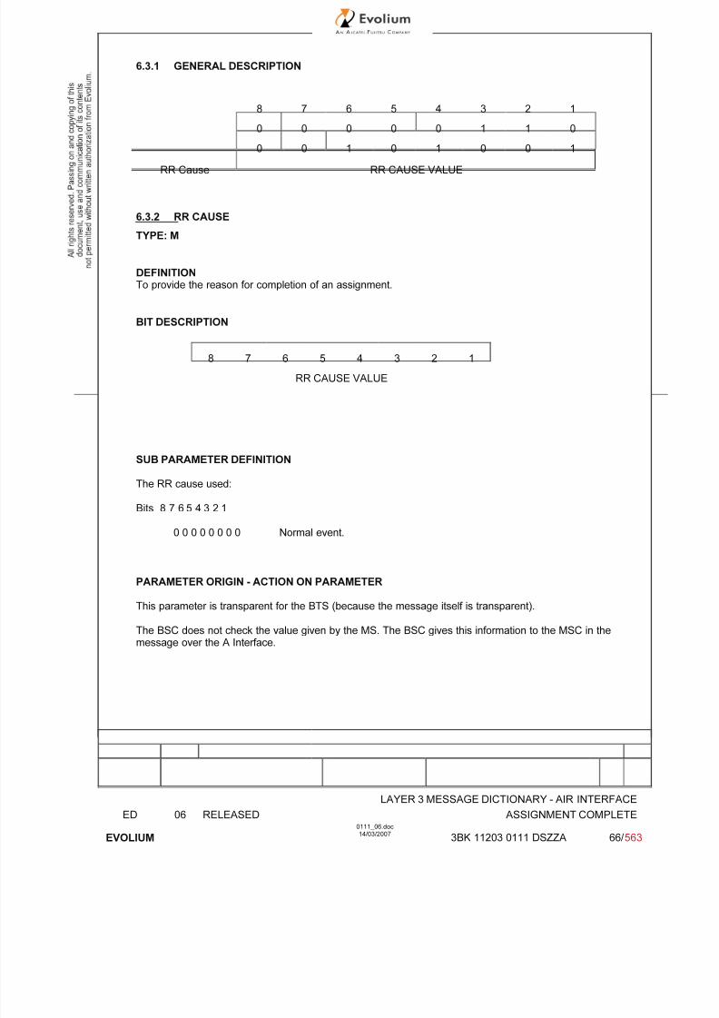
7/11/2019 1. Layer3 Air Interface Messages 0111_06
http://slidepdf.com/reader/full/1-layer3-air-interface-messages-011106 66/562
LAYER 3 MESSAGE DICTIONARY - AIR INTERFACE
ED 06 RELEASED ASSIGNMENT COMPLETE
EVOLIUM
0111_06.doc14/03/2007
3BK 11203 0111 DSZZA 66/ 563
6.3.1 GENERAL DESCRIPTION
8 7 6 5 4 3 2 1
0 0 0 0 0 1 1 0
0 0 1 0 1 0 0 1
RR Cause RR CAUSE VALUE
6.3.2 RR CAUSE
TYPE: M
DEFINITIONTo provide the reason for completion of an assignment.
BIT DESCRIPTION
8 7 6 5 4 3 2 1
RR CAUSE VALUE
SUB PARAMETER DEFINITION
The RR cause used:
Bits 8 7 6 5 4 3 2 1
0 0 0 0 0 0 0 0 Normal event.
PARAMETER ORIGIN - ACTION ON PARAMETER
This parameter is transparent for the BTS (because the message itself is transparent).
The BSC does not check the value given by the MS. The BSC gives this information to the MSC in themessage over the A Interface.

7/11/2019 1. Layer3 Air Interface Messages 0111_06
http://slidepdf.com/reader/full/1-layer3-air-interface-messages-011106 67/562
LAYER 3 MESSAGE DICTIONARY - AIR INTERFACE
ED 06 RELEASED ASSIGNMENT FAILURE
EVOLIUM
0111_06.doc14/03/2007
3BK 11203 0111 DSZZA 67/ 563
6.4 ASSIGNMENT FAILURE
NAME ASSIGNMENT FAILURE
INTERFACE RADIO ABIS A
CHANNEL/ USAGE
SDCCH/FACCH BTS Transparent
3GPP-REF 44.01844.018 08.08
FUNCTION This message is sent on the main DCCH on the old channel from Mobile Stationto the BSC to indicate that the MS has failed to seize the new channel.Used by BSC to report channel seizure failure to the MSC.
DIRECTION From: MS To: BSC
INFORMATION ELEMENT NAME TYPE COMMENT LENGTH(byte)
INFORMATIONELEMENT
LISTHeader RR Cause M V
21
IMPLEMENTATION MAXIMUM LENGTH 3
NORMAL SITUATION ABNORMAL SITUATION TIMER
FOLLOWINGEVENT MSC decides to cancel the
procedure or to reallocate a newchannel T 3107
SPECIFDOC. REF.
Normal assignment procedure (ref. [3])Internal handover (ref. [6])
T3107 is stopped on reception of this message.
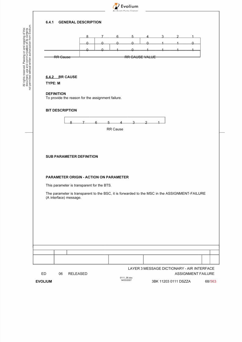
7/11/2019 1. Layer3 Air Interface Messages 0111_06
http://slidepdf.com/reader/full/1-layer3-air-interface-messages-011106 68/562
LAYER 3 MESSAGE DICTIONARY - AIR INTERFACE
ED 06 RELEASED ASSIGNMENT FAILURE
EVOLIUM
0111_06.doc14/03/2007
3BK 11203 0111 DSZZA 68/ 563
6.4.1 GENERAL DESCRIPTION
8 7 6 5 4 3 2 1
0 0 0 0 0 1 1 0
0 0 1 0 1 1 1 1
RR Cause RR CAUSE VALUE
6.4.2 RR CAUSE
TYPE: M
DEFINITIONTo provide the reason for the assignment failure.
BIT DESCRIPTION
8 7 6 5 4 3 2 1
RR Cause
SUB PARAMETER DEFINITION
PARAMETER ORIGIN - ACTION ON PARAMETER
This parameter is transparent for the BTS.
The parameter is transparent to the BSC, it is forwarded to the MSC in the ASSIGNMENT-FAILURE(A interface) message.

7/11/2019 1. Layer3 Air Interface Messages 0111_06
http://slidepdf.com/reader/full/1-layer3-air-interface-messages-011106 69/562
LAYER 3 MESSAGE DICTIONARY - AIR INTERFACE
ED 06 RELEASED CHANNEL MODE MODIFY
EVOLIUM
0111_06.doc14/03/2007
3BK 11203 0111 DSZZA 69/ 563
6.5 CHANNEL MODE MODIFY
NAME CHANNEL MODE MODIFY
INTERFACE RADIO ABIS A
CHANNEL/ USAGE
FACCH BTS Transparent
3GPP-REF 44.01844.018
FUNCTION This message is sent on the FACCH from the BSC to the Mobile Station tochange the channel mode, for in-call modification.See Note 3
DIRECTION From BSC To MS
INFORMATION ELEMENT NAME TYPE COMMENT LENGTH(byte)
INFORMATIONELEMENT
LISTHeader Channel DescriptionChannel ModeVGCS target mode IndicationMultiRate configuration
M V M V M V O TO TV
(Note 1)
Not used(Note 2)
2312
4-8
IMPLEMENTATION MAXIMUM LENGTH 6
NORMAL SITUATION ABNORMAL SITUATION TIMER
FOLLOWINGEVENT CHANNEL MODE
MODIFY ACK (new mode)T9112 expiry,
CHANNEL MODEMODIFY ACK (old mode)
StartT9112
SPECIFDOC. REF.
Channel modification (ref. [8])
Note 1: TCH/H + TCH/H configuration is not supported for this release.
Note 2: This field is only included for calls established with AMR codec.
Note 3 : This message is not used in VGCS context .

7/11/2019 1. Layer3 Air Interface Messages 0111_06
http://slidepdf.com/reader/full/1-layer3-air-interface-messages-011106 70/562
LAYER 3 MESSAGE DICTIONARY - AIR INTERFACE
ED 06 RELEASED CHANNEL MODE MODIFY
EVOLIUM
0111_06.doc14/03/2007
3BK 11203 0111 DSZZA 70/ 563
6.5.1 GENERAL DESCRIPTION
8 7 6 5 4 3 2 1
0 0 0 0 0 1 1 0
0 0 0 1 0 0 0 0
Channel type and TDMA offset TN
Channel TSCH=1-> MAIO (high part)
Description H=0-> spare ARFCN (Hpart)
MAIO low part H S N
A R F C N (low part)
Channel Mode Channel Mode
0 0 0 0 0 0 1 1
MultiRateconfiguration
Length (value ≤ 6 )
(Note) MR version NSCB ICMI spare Start mode
Parameters for MultiRate speech (1-5 octets)
Note: This field is only included for calls established with AMR codec.

7/11/2019 1. Layer3 Air Interface Messages 0111_06
http://slidepdf.com/reader/full/1-layer3-air-interface-messages-011106 71/562
LAYER 3 MESSAGE DICTIONARY - AIR INTERFACE
ED 06 RELEASED CHANNEL MODE MODIFY
EVOLIUM
0111_06.doc14/03/2007
3BK 11203 0111 DSZZA 71/ 563
6.5.2 CHANNEL DESCRIPTION - Phase 1
TYPE: M
DEFINITION
To provide a description of an allocatable channel together with its SACCH.
BIT DESCRIPTION
8 7 6 5 4 3 2 1
Channel type and TDMA offset TN 1
TSC H=1-> MAIO (high part) 2
H=0-> spare ARFCN (Hpart)
MAIO low part H S N 3A R F C N (low part)
SUB PARAMETER DEFINITION
Octet 1:
Channel type and TDMA offset:Bits 8 7 6 5 4
0 0 0 0 1 TCH/F + ACCHs0 0 0 1 T TCH/H + ACCHs0 0 1 T T SDCCH/4 + SACCH/C4 or CBCH (SDCCH/4)
0 1 T T T SDCCH/8 + SACCH/C8 or CBCH (SDCCH/8)all other values are reserved
T bit indicates the subchannel number.
TN : Time slot (0 to 7)
Octets 2 and 3:
TSC : Training Sequence Code (0 to 7)
H : "0" Single RF channel"1" RF hopping channel
Channel selector:H = "0": The channel selector field consists of the absolute RF channel number.
Bits 4 30 0 spare
ARFCN:Octet 2 Bits 2,1 High part of ARFCNOctet 3 Bits 8 to 1 ARFCN low part
The ARFCN is coded as the binary representation of the absolute RF channelNumber.
Range: 0 to 1023.
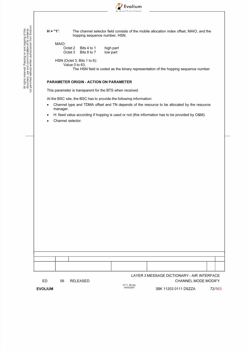
7/11/2019 1. Layer3 Air Interface Messages 0111_06
http://slidepdf.com/reader/full/1-layer3-air-interface-messages-011106 72/562
LAYER 3 MESSAGE DICTIONARY - AIR INTERFACE
ED 06 RELEASED CHANNEL MODE MODIFY
EVOLIUM
0111_06.doc14/03/2007
3BK 11203 0111 DSZZA 72/ 563
H = "1": The channel selector field consists of the mobile allocation index offset, MAIO, and thehopping sequence number, HSN.
MAIO:Octet 2 Bits 4 to 1 high part
Octet 3 Bits 8 to 7 low part
HSN (Octet 3, Bits 1 to 6):Value 0 to 63.
The HSN field is coded as the binary representation of the hopping sequence number.
PARAMETER ORIGIN - ACTION ON PARAMETER
This parameter is transparent for the BTS when received.
At the BSC site, the BSC has to provide the following information:
• Channel type and TDMA offset and TN depends of the resource to be allocated by the resource
manager.
• H: fixed value according if hopping is used or not (this information has to be provided by O&M).
• Channel selector.

7/11/2019 1. Layer3 Air Interface Messages 0111_06
http://slidepdf.com/reader/full/1-layer3-air-interface-messages-011106 73/562
LAYER 3 MESSAGE DICTIONARY - AIR INTERFACE
ED 06 RELEASED CHANNEL MODE MODIFY
EVOLIUM
0111_06.doc14/03/2007
3BK 11203 0111 DSZZA 73/ 563
6.5.3 Channel Description / CHANNEL DESCRIPTION 2 - Phase2
TYPE: M
DEFINITION
To provide a description of an allocatable channel together with its SACCH.
BIT DESCRIPTION
8 7 6 5 4 3 2 1
Channel type and TDMA offset TN 1
TSC H=1-> MAIO (high part) 2
H=0-> spare ARFCN (Hpart)
MAIO low part H S N 3
A R F C N (low part)

7/11/2019 1. Layer3 Air Interface Messages 0111_06
http://slidepdf.com/reader/full/1-layer3-air-interface-messages-011106 74/562
LAYER 3 MESSAGE DICTIONARY - AIR INTERFACE
ED 06 RELEASED CHANNEL MODE MODIFY
EVOLIUM
0111_06.doc14/03/2007
3BK 11203 0111 DSZZA 74/ 563
SUB PARAMETER DEFINITION
Octet 1:
Channel type and TDMA offset:Bits 8 7 6 5 4
0 0 0 0 0 TCH/F + FACCH/F and SACCH/M at the timeslot indicated by TN, and
additional bidirectional or undirectional TCH/Fs and SACCH/Ms according tothe multislot allocation information element0 0 0 0 1 TCH/F + FACCH/F and SACCH/F ACCHs0 0 0 1 T TCH/H + ACCHs0 0 1 T T SDCCH/4 + SACCH/C4 or CBCH (SDCCH/4)0 1 T T T SDCCH/8 + SACCH/C8 or CBCH (SDCCH/8)In the description below "n" is the timeslot number indicated by TN. The description is validonly if all the indicated timeslot numbers are in the range 0 to 7.1 0 X X X TCH/F + FACCH/F and SACCH/M at the time slot indicated by TN, and
additional bidirectional TCH/Fs and SACCH/Ms at other timeslots according tothe following:
X X X:0 0 0 no additional timeslot
0 0 1 at timeslot n-10 1 0 at timeslot n+1, n-10 1 1 at timeslot n+1, n-1 and n-21 0 0 at timeslot n+1, n-1, n-2, and n-31 0 1 at timeslot n+1, n-1, n-2, n-3 and n-41 1 0 at timeslot n+1, n-1, n-2, n-3, n-4 and n-51 1 1 at timeslot n+1, n-1, n-2, n-3, n-4, n-5 and n-6
1 1 0 0 1to1 1 0 1 1
TCH/F + FACCH/F and SACCH/M at the time slot indicated by TN and additionaunidirectional TCH/FDs and SACCH/MDs at other timeslots according to thefollowing:
1 1 0 0 1 at timeslot n-11 1 0 1 0 at timeslot n+1, n-11 1 0 1 1 at timeslot n+1, n-1 and n-2
1 1 1 1 0 TCH/F + FACCH/F and SACCH/M at the time slot indicated by TN andadditional bidirectional TCH/F and SACCH/M at timeslot n+1 and unidirectionalTCH/FD and SACCH/MD at timeslot n-1All other values are reserved
T bit indicates the subchannel number.
TN : Time slot (0 to 7)
Octets 2 and 3:
TSC : Training Sequence Code (0 to 7)
H : "0" Single RF channel"1" RF hopping channel
Channel selector:
H = "0": The channel selector field consists of the absolute RF channel number.Bits 4 3
0 0 spareARFCN:
Octet 2 Bits 2,1 High part of ARFCNOctet 3 Bits 8 to 1 ARFCN low part
The ARFCN is coded as the binary representation of the absolute RF channel
Number.

7/11/2019 1. Layer3 Air Interface Messages 0111_06
http://slidepdf.com/reader/full/1-layer3-air-interface-messages-011106 75/562
LAYER 3 MESSAGE DICTIONARY - AIR INTERFACE
ED 06 RELEASED CHANNEL MODE MODIFY
EVOLIUM
0111_06.doc14/03/2007
3BK 11203 0111 DSZZA 75/ 563
Range: 0 to 1023.
H = "1": The channel selector field consists of the mobile allocation index offset, MAIO, and thehopping sequence number, HSN.
MAIO:Octet 2 Bits 4 to 1 high partOctet 3 Bits 8 to 7 low part
HSN (Octet 3, Bits 1 to 6):Value 0 to 63.
The HSN field is coded as the binary representation of the hopping sequence number.
PARAMETER ORIGIN - ACTION ON PARAMETER
This parameter is transparent for the BTS when received.
At the BSC site, the BSC has to provide the following information:• Channel type and TDMA offset and TN depends of the resource to be allocated by the resource
manager.
• H: fixed value according if hopping is used or not (this information has to be provided by O&M).
• Channel selector.

7/11/2019 1. Layer3 Air Interface Messages 0111_06
http://slidepdf.com/reader/full/1-layer3-air-interface-messages-011106 76/562
LAYER 3 MESSAGE DICTIONARY - AIR INTERFACE
ED 06 RELEASED CHANNEL MODE MODIFY
EVOLIUM
0111_06.doc14/03/2007
3BK 11203 0111 DSZZA 76/ 563
6.5.4 CHANNEL MODE
TYPE M
DEFINITION :The channel mode information element gives the mode of encoding, decoding and transcoding.
BIT DESCRIPTION
8 7 6 5 4 3 2 1
mode
SUB PARAMETER DEFINITION
The mode field is encoded as follows:Bits 8 7 6 5 4 3 2 1
0 0 0 0 0 0 0 0 signaling only0 0 0 0 0 0 0 1 speech full (rate or half rate version 1)
0 0 1 0 0 0 0 1 speech (full rate or half rate version 2)0 1 0 0 0 0 0 1 speech (full rate or half rate version 3)0 0 0 0 1 1 1 1 data 14.5 kbit/s radio interface rate not supported0 0 0 0 0 0 1 1 data 12 kbit/s radio interface rate0 0 0 0 1 0 1 1 data 6 kbit/s radio interface rate0 0 0 1 0 0 1 1 data 3.6 kbit/s radio interface rate
All other values are reserved and not supported.
PARAMETER ORIGIN - ACTION ON PARAMETER
This parameter is deduced from the A interface Channel Type IE.
Data rates received on the A interface which are lower than 2.4 kbit/s are mapped onto the "data 3.6kbit/s radio interface rate" value in this element.

7/11/2019 1. Layer3 Air Interface Messages 0111_06
http://slidepdf.com/reader/full/1-layer3-air-interface-messages-011106 77/562
LAYER 3 MESSAGE DICTIONARY - AIR INTERFACE
ED 06 RELEASED CHANNEL MODE MODIFY
EVOLIUM
0111_06.doc14/03/2007
3BK 11203 0111 DSZZA 77/ 563
6.5.5 MULTIRATE CONFIGURATION
TYPE: O
DEFINITION :The MultiRate Configuration information element gives all parameters related to a MultiRate speechcodec.
BIT DESCRIPTION
8 7 6 5 4 3 2 1
0 0 0 0 0 0 1 1 octet 1
Lengthoctet 2
MR version NSCB ICMI spare Start mode octet 3
Parameters for MultiRate speech octet 4
.
.
octet n (n ≤ 8)
SUB PARAMETER DEFINITION
Octet 3MR version (MultiRate speech version):Bits 8 7 6
0 0 1 Adaptive MultiRate speech version 1all other values are reserved.
NSCB (Noise Suppression Control Bit):Bit 5
0 Noise Suppression can be used (default)1 Noise Suppression shall be turned off
ICMI (Initial Codec Mode Indicator):Bit 4
0 The initial codec mode is defined by the implicit rule provided in 3GPP TS 05.091 The initial codec mode is defined by the Start Mode field
Bit 30 Spare
Start Mode:Bits 2 1
x x The initial codec mode is coded as in 3GPP TS 05.09 section 3.4.1
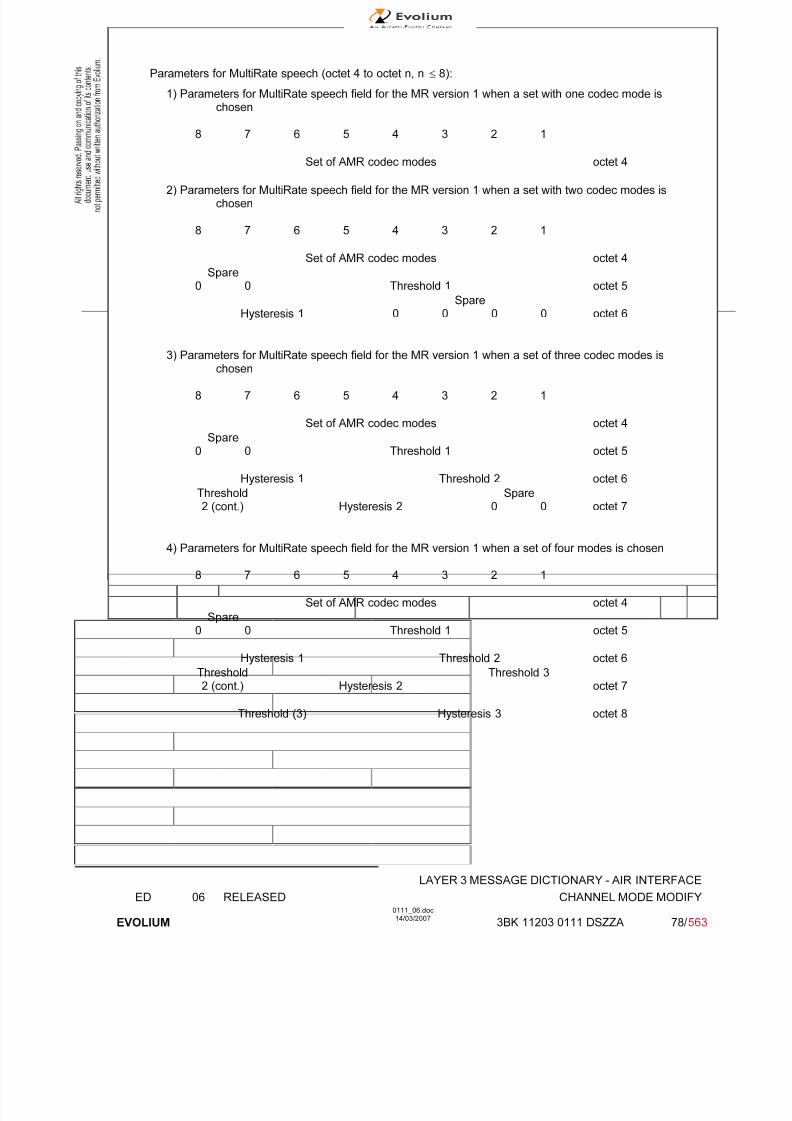
7/11/2019 1. Layer3 Air Interface Messages 0111_06
http://slidepdf.com/reader/full/1-layer3-air-interface-messages-011106 78/562
LAYER 3 MESSAGE DICTIONARY - AIR INTERFACE
ED 06 RELEASED CHANNEL MODE MODIFY
EVOLIUM
0111_06.doc14/03/2007
3BK 11203 0111 DSZZA 78/ 563
Parameters for MultiRate speech (octet 4 to octet n, n ≤ 8):
1) Parameters for MultiRate speech field for the MR version 1 when a set with one codec mode ischosen
8 7 6 5 4 3 2 1
Set of AMR codec modes octet 4
2) Parameters for MultiRate speech field for the MR version 1 when a set with two codec modes ischosen
8 7 6 5 4 3 2 1
Set of AMR codec modes octet 4
Spare0 0 Threshold 1 octet 5
SpareHysteresis 1 0 0 0 0 octet 6
3) Parameters for MultiRate speech field for the MR version 1 when a set of three codec modes ischosen
8 7 6 5 4 3 2 1
Set of AMR codec modes octet 4
Spare0 0 Threshold 1 octet 5
Hysteresis 1 Threshold 2 octet 6
Threshold Spare2 (cont.) Hysteresis 2 0 0 octet 7
4) Parameters for MultiRate speech field for the MR version 1 when a set of four modes is chosen
8 7 6 5 4 3 2 1
Set of AMR codec modes octet 4
Spare0 0 Threshold 1 octet 5
Hysteresis 1 Threshold 2 octet 6
Threshold Threshold 3
2 (cont.) Hysteresis 2 octet 7
Threshold (3) Hysteresis 3 octet 8

7/11/2019 1. Layer3 Air Interface Messages 0111_06
http://slidepdf.com/reader/full/1-layer3-air-interface-messages-011106 79/562
LAYER 3 MESSAGE DICTIONARY - AIR INTERFACE
ED 06 RELEASED CHANNEL MODE MODIFY
EVOLIUM
0111_06.doc14/03/2007
3BK 11203 0111 DSZZA 79/ 563
Set of adaptive MultiRate codec modes field (octet 4)
Bit 8 0 12,2 kbit/s codec rate is not part of the subset;1 12,2 kbit/s codec rate is part of the subset;
Bit 7 0 10,2 kbit/s codec rate is not part of the subset;1 10,2 kbit/s codec rate is part of the subset;
Bit 6 0 7,95 kbit/s codec rate is not part of the subset;1 7,95 kbit/s codec rate is part of the subset;
Bit 5 0 7,40 kbit/s codec rate is not part of the subset;1 7,40 kbit/s codec rate is part of the subset;
Bit 4 0 6,70 kbit/s codec rate is not part of the subset;1 6,70 kbit/s codec rate is part of the subset;
Bit 3 0 5,90 kbit/s codec rate is not part of the subset;
1 5,90 kbit/s codec rate is part of the subset;Bit 2 0 5,15 kbit/s codec rate is not part of the subset;
1 5,15 kbit/s codec rate is part of the subset;Bit 1 0 4,75 kbit/s codec rate is not part of the subset;
1 4,75 kbit/s codec rate is part of the subset;
Threshold j (6 bits), see Note 1
Coded as the binary representation of a value N. N corresponds to the threshold of C/I in dB,as defined in 3GPP TS 05.09;
Hysteresis j (4 bits), see Note 1
Coded as the binary representation of the hysteresis value associated to THRj, as defined in3GPP TS 05.09.
Note 1: j = 1 corresponds to the lowest value of threshold in dB, j = 2 to the second lowest, j = 3 to thehighest value.

7/11/2019 1. Layer3 Air Interface Messages 0111_06
http://slidepdf.com/reader/full/1-layer3-air-interface-messages-011106 80/562
LAYER 3 MESSAGE DICTIONARY - AIR INTERFACE
ED 06 RELEASED CHANNEL MODE MODIFY ACK
EVOLIUM
0111_06.doc14/03/2007
3BK 11203 0111 DSZZA 80/ 563
6.6 CHANNEL MODE MODIFY ACK
NAME CHANNEL MODE MODIFY ACK
INTERFACE RADIO ABIS A
CHANNEL/ USAGE
FACCH BTS Transparent
3GPP-REF 44.01844.018
FUNCTION This message is sent on the FACCH from the Mobile Station to the BSC toacknowledge the requested change of mode, for in-call modification.To indicate successful change of mode or that the old mode is valid.
DIRECTION From MS To BSC
INFORMATION ELEMENT NAME TYPE COMMENT LENGTH(byte)
INFORMATIONELEMENT
LISTHeader Channel DescriptionChannel Mode
M V M V M V
231
IMPLEMENTATION MAXIMUM LENGTH 6
NORMAL SITUATION ABNORMAL SITUATION TIMER
FOLLOWING
EVENT StopT9112
SPECIFDOC. REF.
Channel modification (ref. [8])

7/11/2019 1. Layer3 Air Interface Messages 0111_06
http://slidepdf.com/reader/full/1-layer3-air-interface-messages-011106 81/562
LAYER 3 MESSAGE DICTIONARY - AIR INTERFACE
ED 06 RELEASED CHANNEL MODE MODIFY ACK
EVOLIUM
0111_06.doc14/03/2007
3BK 11203 0111 DSZZA 81/ 563
6.6.1 GENERAL DESCRIPTION
8 7 6 5 4 3 2 1
0 0 0 0 0 1 1 0
0 0 0 1 0 1 1 1
Channel type and TDMA offset TN
Channel TSCH=1-> MAIO (high part)
Description H=0-> spare ARFCN (Hpart)
MAIO low part H S N
A R F C N (low part)
Channel Mode Channel Mode
6.6.2 CHANNEL DESCRIPTION - Phase 1
TYPE: M
DEFINITION
To provide a description of an allocatable channel together with its SACCH.
BIT DESCRIPTION
8 7 6 5 4 3 2 1
Channel type and TDMA offset TN 1
TSC H=1-> MAIO (high part) 2
H=0-> spare ARFCN (Hpart)
MAIO low part H S N 3
A R F C N (low part)
SUB PARAMETER DEFINITION
Octet 1:
Channel type and TDMA offset:Bits 8 7 6 5 4
0 0 0 0 1 TCH/F + ACCHs0 0 0 1 T TCH/H + ACCHs0 0 1 T T SDCCH/4 + SACCH/C4 or CBCH (SDCCH/4)0 1 T T T SDCCH/8 + SACCH/C8 or CBCH (SDCCH/8)
all other values are reserved.
T bit indicates the subchannel number.
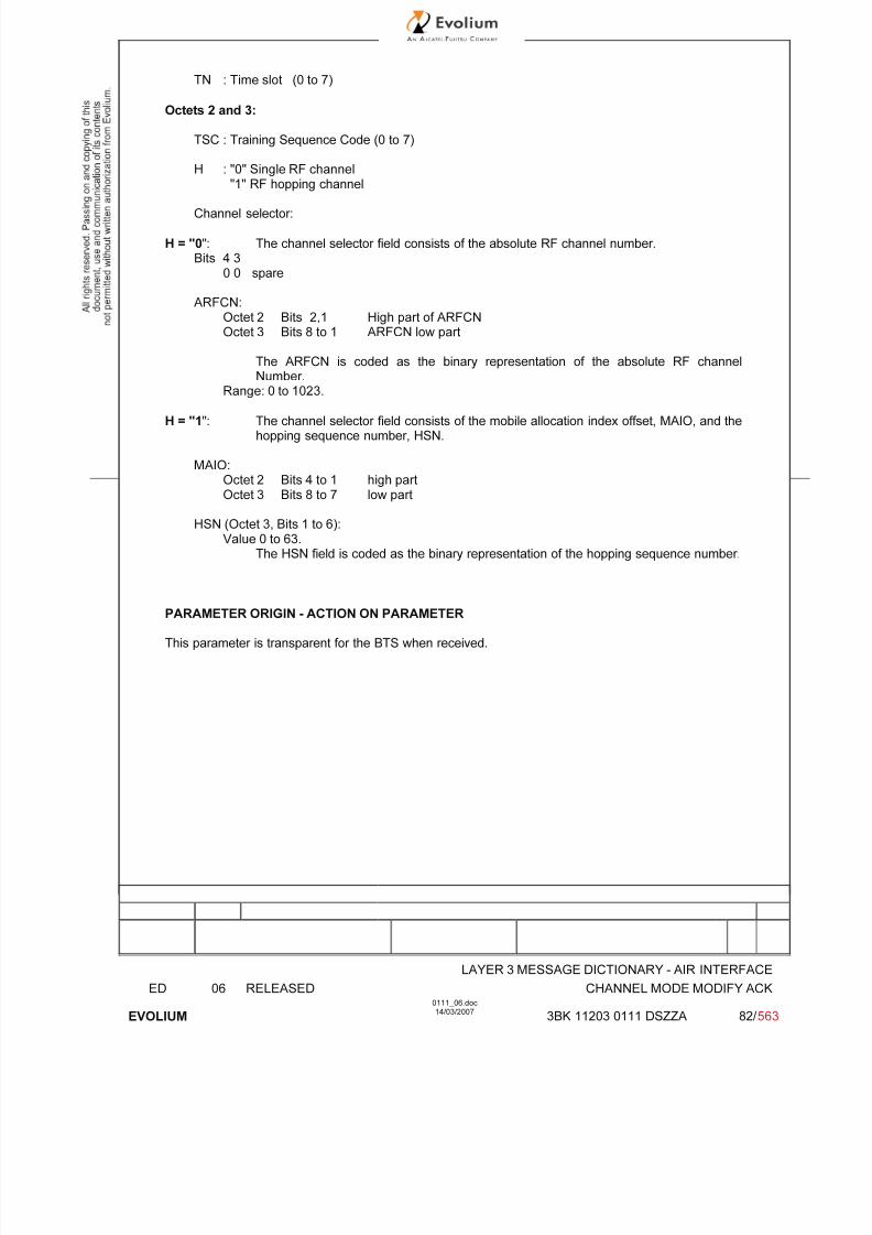
7/11/2019 1. Layer3 Air Interface Messages 0111_06
http://slidepdf.com/reader/full/1-layer3-air-interface-messages-011106 82/562
LAYER 3 MESSAGE DICTIONARY - AIR INTERFACE
ED 06 RELEASED CHANNEL MODE MODIFY ACK
EVOLIUM
0111_06.doc14/03/2007
3BK 11203 0111 DSZZA 82/ 563
TN : Time slot (0 to 7)
Octets 2 and 3:
TSC : Training Sequence Code (0 to 7)
H : "0" Single RF channel
"1" RF hopping channel
Channel selector:
H = "0": The channel selector field consists of the absolute RF channel number.Bits 4 3
0 0 spare
ARFCN:Octet 2 Bits 2,1 High part of ARFCNOctet 3 Bits 8 to 1 ARFCN low part
The ARFCN is coded as the binary representation of the absolute RF channel
Number.Range: 0 to 1023.
H = "1": The channel selector field consists of the mobile allocation index offset, MAIO, and thehopping sequence number, HSN.
MAIO:Octet 2 Bits 4 to 1 high partOctet 3 Bits 8 to 7 low part
HSN (Octet 3, Bits 1 to 6):Value 0 to 63.
The HSN field is coded as the binary representation of the hopping sequence number.
PARAMETER ORIGIN - ACTION ON PARAMETER
This parameter is transparent for the BTS when received.
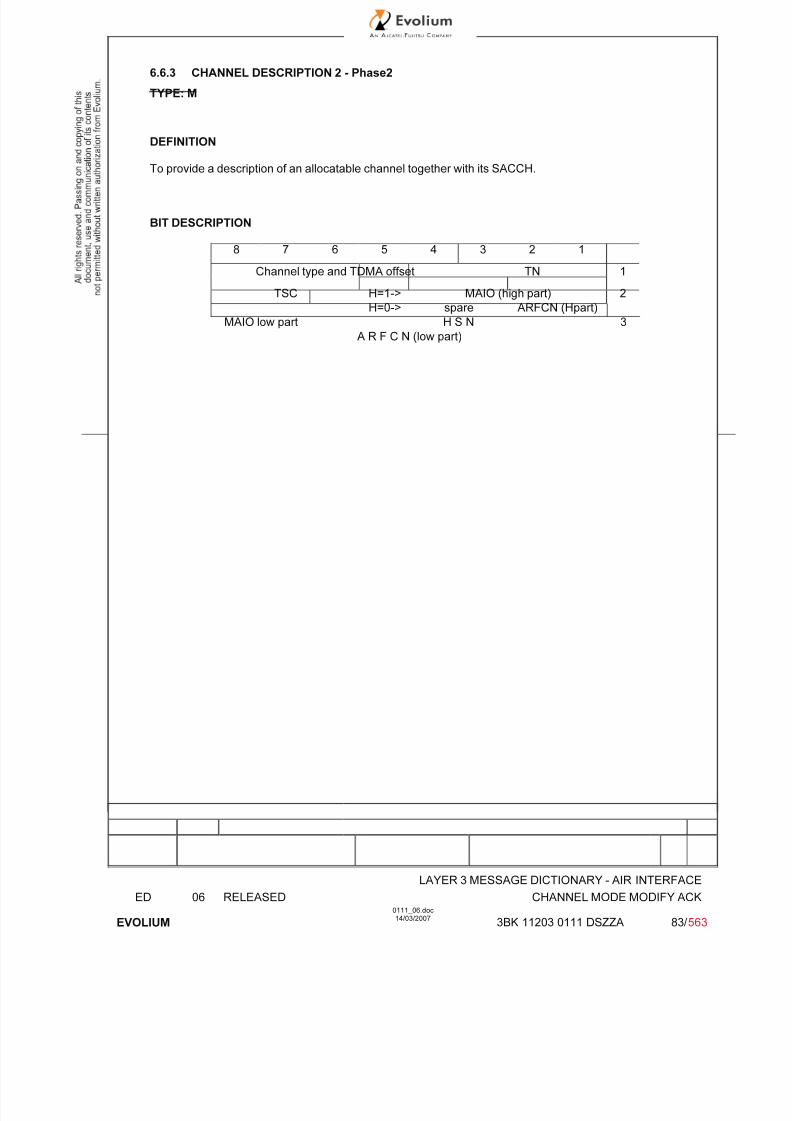
7/11/2019 1. Layer3 Air Interface Messages 0111_06
http://slidepdf.com/reader/full/1-layer3-air-interface-messages-011106 83/562
LAYER 3 MESSAGE DICTIONARY - AIR INTERFACE
ED 06 RELEASED CHANNEL MODE MODIFY ACK
EVOLIUM
0111_06.doc14/03/2007
3BK 11203 0111 DSZZA 83/ 563
6.6.3 CHANNEL DESCRIPTION 2 - Phase2
TYPE: M
DEFINITION
To provide a description of an allocatable channel together with its SACCH.
BIT DESCRIPTION
8 7 6 5 4 3 2 1
Channel type and TDMA offset TN 1
TSC H=1-> MAIO (high part) 2
H=0-> spare ARFCN (Hpart)
MAIO low part H S N 3
A R F C N (low part)
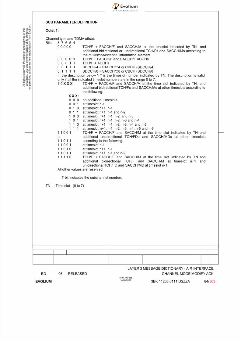
7/11/2019 1. Layer3 Air Interface Messages 0111_06
http://slidepdf.com/reader/full/1-layer3-air-interface-messages-011106 84/562
LAYER 3 MESSAGE DICTIONARY - AIR INTERFACE
ED 06 RELEASED CHANNEL MODE MODIFY ACK
EVOLIUM
0111_06.doc14/03/2007
3BK 11203 0111 DSZZA 84/ 563
SUB PARAMETER DEFINITION
Octet 1:
Channel type and TDMA offset:Bits 8 7 6 5 4
0 0 0 0 0 TCH/F + FACCH/F and SACCH/M at the timeslot indicated by TN, and
additional bidirectional or undirectional TCH/Fs and SACCH/Ms according tothe multislot allocation information element0 0 0 0 1 TCH/F + FACCH/F and SACCH/F ACCHs0 0 0 1 T TCH/H + ACCHs0 0 1 T T SDCCH/4 + SACCH/C4 or CBCH (SDCCH/4)0 1 T T T SDCCH/8 + SACCH/C8 or CBCH (SDCCH/8)In the description below "n" is the timeslot number indicated by TN. The description is validonly if all the indicated timeslot numbers are in the range 0 to 7.1 0 X X X TCH/F + FACCH/F and SACCH/M at the time slot indicated by TN, and
additional bidirectional TCH/Fs and SACCH/Ms at other timeslots according tothe following:
X X X:0 0 0 no additional timeslots
0 0 1 at timeslot n-10 1 0 at timeslot n+1, n-10 1 1 at timeslot n+1, n-1 and n-21 0 0 at timeslot n+1, n-1, n-2, and n-31 0 1 at timeslot n+1, n-1, n-2, n-3 and n-41 1 0 at timeslot n+1, n-1, n-2, n-3, n-4 and n-51 1 1 at timeslot n+1, n-1, n-2, n-3, n-4, n-5 and n-6
1 1 0 0 1to1 1 0 1 1
TCH/F + FACCH/F and SACCH/M at the time slot indicated by TN andadditional unidirectional TCH/FDs and SACCH/MDs at other timeslotsaccording to the following:
1 1 0 0 1 at timeslot n-11 1 0 1 0 at timeslot n+1, n-11 1 0 1 1 at timeslot n+1, n-1 and n-2
1 1 1 1 0 TCH/F + FACCH/F and SACCH/M at the time slot indicated by TN andadditional bidirectional TCH/F and SACCH/M at timeslot n+1 andunidirectional TCH/FD and SACCH/MD at timeslot n-1
All other values are reserved
T bit indicates the subchannel number.
TN : Time slot (0 to 7)

7/11/2019 1. Layer3 Air Interface Messages 0111_06
http://slidepdf.com/reader/full/1-layer3-air-interface-messages-011106 85/562
LAYER 3 MESSAGE DICTIONARY - AIR INTERFACE
ED 06 RELEASED CHANNEL MODE MODIFY ACK
EVOLIUM
0111_06.doc14/03/2007
3BK 11203 0111 DSZZA 85/ 563
Octets 2 and 3:
TSC : Training Sequence Code (0 to 7)
H : "0" Single RF channel"1" RF hopping channel
Channel selector:
H = "0": The channel selector field consists of the absolute RF channel number.Bits 4 3
0 0 spareARFCN:
Octet 2 Bits 2,1 High part of ARFCNOctet 3 Bits 8 to 1 ARFCN low part
The ARFCN is coded as the binary representation of the absolute RF channelNumber.
Range: 0 to 1023.
H = "1": The channel selector field consists of the mobile allocation index offset, MAIO, and thehopping sequence number, HSN.
MAIO:Octet 2 Bits 4 to 1 high partOctet 3 Bits 8 to 7 low part
HSN (Octet 3, Bits 1 to 6):Value 0 to 63.
The HSN field is coded as the binary representation of the hopping sequence number.
PARAMETER ORIGIN - ACTION ON PARAMETER
This parameter is transparent for the BTS when received.
At the BSC site, the BSC has to provide the following information:
• Channel type and TDMA offset and TN depends of the resource to be allocated by the resourcemanager.
• H: fixed value according if hopping is used or not (this information has to be provided by O&M).
• Channel selector.

7/11/2019 1. Layer3 Air Interface Messages 0111_06
http://slidepdf.com/reader/full/1-layer3-air-interface-messages-011106 86/562
LAYER 3 MESSAGE DICTIONARY - AIR INTERFACE
ED 06 RELEASED CHANNEL MODE MODIFY ACK
EVOLIUM
0111_06.doc14/03/2007
3BK 11203 0111 DSZZA 86/ 563
6.6.4 CHANNEL MODE
TYPE: M
DEFINITION The channel mode information element gives the mode of encoding, decoding and transcoding.
BIT DESCRIPTION
8 7 6 5 4 3 2 1
mode
SUB PARAMETER DEFINITION
The mode field is encoded as follows:
Bits 8 7 6 5 4 3 2 10 0 0 0 0 0 0 0 signalling only
0 0 0 0 0 0 0 1 speech (full rate or half rate version 1)0 0 1 0 0 0 0 1 speech (full rate or half rate version 2)0 1 0 0 0 0 0 1 speech (full rate or half rate version 3)0 0 0 0 1 1 1 1 data 14.5 kbit/s radio interface rate not supported0 0 0 0 0 0 1 1 data 12 kbit/s radio interface rate0 0 0 0 1 0 1 1 data 6 kbit/s radio interface rate0 0 0 1 0 0 1 1 data 3.6 kbit/s radio interface rate
All other values are reserved and not supported.
PARAMETER ORIGIN - ACTION ON PARAMETER
The MS sets this parameter according to the applied new rate or according to the old one.
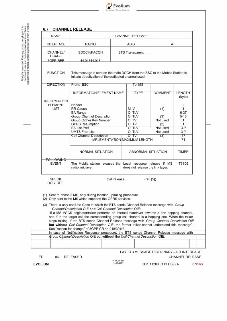
7/11/2019 1. Layer3 Air Interface Messages 0111_06
http://slidepdf.com/reader/full/1-layer3-air-interface-messages-011106 87/562
LAYER 3 MESSAGE DICTIONARY - AIR INTERFACE
ED 06 RELEASED CHANNEL RELEASE
EVOLIUM
0111_06.doc14/03/2007
3BK 11203 0111 DSZZA 87/ 563
6.7 CHANNEL RELEASE
NAME CHANNEL RELEASE
INTERFACE RADIO ABIS A
CHANNEL/ USAGE
SDCCH/FACCH BTS Transparent
3GPP-REF 44.01844.018
FUNCTION This message is sent on the main DCCH from the BSC to the Mobile Station toinitiate deactivation of the dedicated channel used.
DIRECTION From: BSC To: MS
INFORMATION ELEMENT NAME TYPE COMMENT LENGTH(byte)
INFORMATIONELEMENT
LISTHeader RR CauseBA RangeGroup Channel DescriptionGroup Cipher Key Number GPRS ResumptionBA List Pref UMTS Freq ListCell Channel Description
M V O TLV O TLV C TV O TV O TLV O TLV O TV
(1)
(3)Not used
(2)Not usedNot used
(3)
21
6-375-13
11
3-?3-?17
IMPLEMENTATION MAXIMUM LENGTH 71
NORMAL SITUATION ABNORMAL SITUATION TIMER
FOLLOWINGEVENT The Mobile station releases the
radio link layer Local resource release if MSdoes not release the link layer.
T3109
SPECIFDOC. REF.
Call release (ref. [5])
(1) Sent to phase 2 MS, only during location updating procedure.
(2) Only sent to the MS which supports the GPRS services.
(3) There is only one Use Case in which the BTS sends Channel Release message with Group
Channel Description OIE and Cell Channel Description OIE:
“If a MS VGCS originator/talker performs an intercell handover towards a non hopping channel,
and if in the target cell the corresponding group call channel is a hopping one. When the talker
stops talking, if the BTS sends Channel Release message with Group Channel Description OIE
but without Cell Channel Description OIE, the former talker cannot understand this message”.
See “reason for change” of 3GPP CR 44.018/301r2.In case of Notification Response procedure, the BTS sends Channel Release message withGroup Channel Description OIE but without the Cell Channel Description OIE.
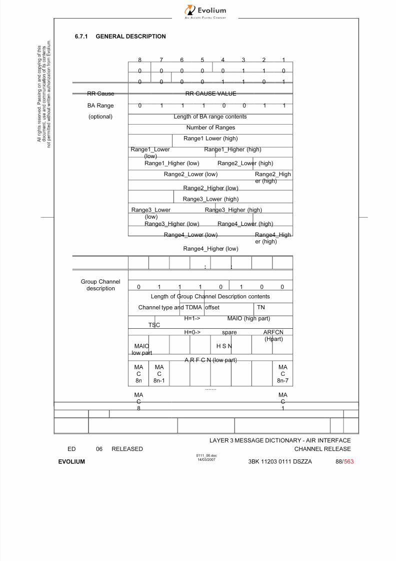
7/11/2019 1. Layer3 Air Interface Messages 0111_06
http://slidepdf.com/reader/full/1-layer3-air-interface-messages-011106 88/562
LAYER 3 MESSAGE DICTIONARY - AIR INTERFACE
ED 06 RELEASED CHANNEL RELEASE
EVOLIUM
0111_06.doc14/03/2007
3BK 11203 0111 DSZZA 88/ 563
6.7.1 GENERAL DESCRIPTION
8 7 6 5 4 3 2 1
0 0 0 0 0 1 1 0
0 0 0 0 1 1 0 1
RR Cause RR CAUSE VALUE
BA Range 0 1 1 1 0 0 1 1
(optional) Length of BA range contents
Number of Ranges
Range1 Lower (high)
Range1_Lower (low)
Range1_Higher (high)
Range1_Higher (low) Range2_Lower (high)
Range2_Lower (low) Range2_Higher (high)
Range2_Higher (low)
Range3_Lower (high)
Range3_Lower (low)
Range3_Higher (high)
Range3_Higher (low) Range4_Lower (high)
Range4_Lower (low) Range4_Higher (high)
Range4_Higher (low)
: :
Group Channeldescription 0 1 1 1 0 1 0 0
Length of Group Channel Description contents
Channel type and TDMA offset TN
TSCH=1-> MAIO (high part)
H=0-> spare ARFCN(Hpart)
MAIOlow part
H S N
A R F C N (low part)
MAC8n
MAC
8n-1
MAC
8n-7
.......
MAC8
MAC1

7/11/2019 1. Layer3 Air Interface Messages 0111_06
http://slidepdf.com/reader/full/1-layer3-air-interface-messages-011106 89/562
LAYER 3 MESSAGE DICTIONARY - AIR INTERFACE
ED 06 RELEASED CHANNEL RELEASE
EVOLIUM
0111_06.doc14/03/2007
3BK 11203 0111 DSZZA 89/ 563
GPRS Resumption(optional, GPRS
MS only
1 1 0 0 0Spare
0Spare
0Spare
ACK
Cell ChannelDescription 0 1 1 0 0 0 1 0
Bit
128
Bit
127
0
spare
0
spare
Bit
124
Bit
123
Bit
122
Bit
121
Bit120
Bit119
Bit118
Bit117
Bit116
Bit115
Bit114
Bit113
Bit008
Bit007
Bit006
Bit005
Bit004
Bit003
Bit002
Bit001
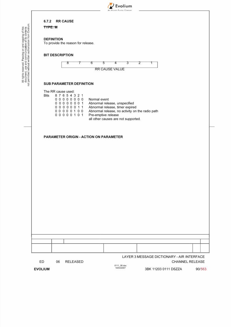
7/11/2019 1. Layer3 Air Interface Messages 0111_06
http://slidepdf.com/reader/full/1-layer3-air-interface-messages-011106 90/562
LAYER 3 MESSAGE DICTIONARY - AIR INTERFACE
ED 06 RELEASED CHANNEL RELEASE
EVOLIUM
0111_06.doc14/03/2007
3BK 11203 0111 DSZZA 90/ 563
6.7.2 RR CAUSE
TYPE: M
DEFINITIONTo provide the reason for release.
BIT DESCRIPTION
8 7 6 5 4 3 2 1
RR CAUSE VALUE
SUB PARAMETER DEFINITION
The RR cause used:Bits 8 7 6 5 4 3 2 1
0 0 0 0 0 0 0 0 Normal event0 0 0 0 0 0 0 1 Abnormal release, unspecified0 0 0 0 0 0 1 1 Abnormal release, timer expired0 0 0 0 0 1 0 0 Abnormal release, no activity on the radio path0 0 0 0 0 1 0 1 Pre-emptive release
all other causes are not supported.
PARAMETER ORIGIN - ACTION ON PARAMETER
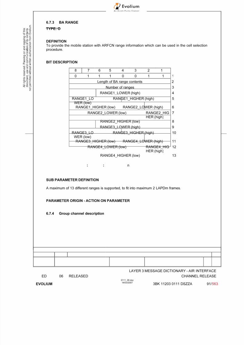
7/11/2019 1. Layer3 Air Interface Messages 0111_06
http://slidepdf.com/reader/full/1-layer3-air-interface-messages-011106 91/562
LAYER 3 MESSAGE DICTIONARY - AIR INTERFACE
ED 06 RELEASED CHANNEL RELEASE
EVOLIUM
0111_06.doc14/03/2007
3BK 11203 0111 DSZZA 91/ 563
6.7.3 BA RANGE
TYPE: O
DEFINITIONTo provide the mobile station with ARFCN range information which can be used in the cell selectionprocedure.
BIT DESCRIPTION
8 7 6 5 4 3 2 1
0 1 1 1 0 0 1 1 1
Length of BA range contents 2
Number of ranges 3
RANGE1_LOWER (high) 4
RANGE1_LOWER (low)
RANGE1_HIGHER (high) 5
RANGE1_HIGHER (low) RANGE2_LOWER (high) 6
RANGE2_LOWER (low) RANGE2_HIGHER (high)
7
RANGE2_HIGHER (low) 8
RANGE3_LOWER (high) 9
RANGE3_LOWER (low)
RANGE3_HIGHER (high) 10
RANGE3_HIGHER (low) RANGE4_LOWER (high) 11
RANGE4_LOWER (low) RANGE4_HIGHER (high)
12
RANGE4_HIGHER (low) 13
: : n
SUB PARAMETER DEFINITION
A maximum of 13 different ranges is supported, to fit into maximum 2 LAPDm frames.
PARAMETER ORIGIN - ACTION ON PARAMETER
6.7.4 Group channel description
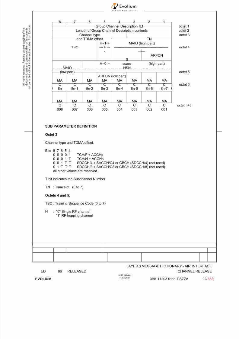
7/11/2019 1. Layer3 Air Interface Messages 0111_06
http://slidepdf.com/reader/full/1-layer3-air-interface-messages-011106 92/562
LAYER 3 MESSAGE DICTIONARY - AIR INTERFACE
ED 06 RELEASED CHANNEL RELEASE
EVOLIUM
0111_06.doc14/03/2007
3BK 11203 0111 DSZZA 92/ 563
8 7 6 5 4 3 2 1
Group Channel Description IEI octet 1
Length of Group Channel Description contents octet 2
Channel typeand TDMA offset TN
octet 3
H=1-> MAIO (high part)TSC --- H --
-
-----------------------------------------------
------
octet 4
H=0->0
spare
ARFCN
(high part)
MAIO(low part)
HSNoctet 5
ARFCN (low part)
MAC8n
MAC
8n-1
MAC
8n-2
MAC
8n-3
MAC
8n-4
MAC
8n-5
MAC
8n-6
MAC
8n-7octet 6
MA
C008
MA
C007
MA
C006
MA
C005
MA
C004
MA
C003
MA
C002
MA
C001
octet n+5
SUB PARAMETER DEFINITION
Octet 3
Channel type and TDMA offset.
Bits 8 7 6 5 4
0 0 0 0 1 TCH/F + ACCHs0 0 0 1 T TCH/H + ACCHs0 0 1 T T SDCCH/4 + SACCH/C4 or CBCH (SDCCH/4) (not used)0 1 T T T SDCCH/8 + SACCH/C8 or CBCH (SDCCH/8) (not used)all other values are reserved.
T bit indicates the Subchannel Number.
TN : Time slot (0 to 7)
Octets 4 and 5:
TSC : Training Sequence Code (0 to 7)
H : "0" Single RF channel"1" RF hopping channel

7/11/2019 1. Layer3 Air Interface Messages 0111_06
http://slidepdf.com/reader/full/1-layer3-air-interface-messages-011106 93/562
LAYER 3 MESSAGE DICTIONARY - AIR INTERFACE
ED 06 RELEASED CHANNEL RELEASE
EVOLIUM
0111_06.doc14/03/2007
3BK 11203 0111 DSZZA 93/ 563
Channel selector:
H = "0": The channel selector field consists of the absolute RF channel number.Bits 4 3
0 0 spare
ARFCN:
Octet2 Bits 2,1 High part of ARFCNOctet 3 Bits 8 to 1 ARFCN low part
The ARFCN is coded as the binary representation of the absolute RF channelNumber.
Range 0 to 1023.
H = "1": The channel selector field consists of the mobile allocation index offset, MAIO, and thehopping sequence number, HSN.
MAIO:
Octet 2 Bits 4 to 1 High partOctet 3 Bits 8 to 7 Low part
HSN (Octet 3, Bits 1 to 6):Value 0 to 63.
The HSN field is coded as the binary representation of the hopping sequence number.
Octet 6 – (n+5)
MA length depends on the relative frequency span of the frequencies in the cell allocation frequencylist
MA Ci:
Mobile Allocation RF Channel i - the RF channels represented in the MA C i bit fields are those whichin the "Cell Channel Description" information element are coded with "1" in the CA ARFCN N bit fields.
MA Ci = CA ARFCN N(i) i = 1,2...NF
(NF = Number of Frequencies in the CA frequency list).
For a RF channel belonging to the Mobile Allocation the MA C i bit is coded with a "1", for a RF
channel not belonging to the Mobile Allocation, the MA C i bit is coded with a "0". If NF mod 8 ≠ 0 thenbits NF to 8n in octet 3 must be coded with a "0" in each.
PARAMETER ORIGIN - ACTION ON PARAMETER
These parameters are transparent for the BTS when received.
At the BSC site, the BSC has to provide the following information:
• Channel type and TDMA offset and TN depends of the resource to be allocated by theresource manager.
• H: fixed value according if hopping is used or not (this information has to be provided by O&M).
• Channel selector.
• Mobile Allocation Stored and Updated during system reconfiguration.

7/11/2019 1. Layer3 Air Interface Messages 0111_06
http://slidepdf.com/reader/full/1-layer3-air-interface-messages-011106 94/562
LAYER 3 MESSAGE DICTIONARY - AIR INTERFACE
ED 06 RELEASED CHANNEL RELEASE
EVOLIUM
0111_06.doc14/03/2007
3BK 11203 0111 DSZZA 94/ 563
6.7.5 GPRS RESUMPTION
TYPE: O
DEFINITION
The purpose of the GPRS Resumption information element is to indicate whether the network has
successfully resumed GPRS services or not.
BIT DESCRIPTION
8 7 6 5 4 3 2 1
1 1 0 0 0 0 0 ACK
IEI Spare Spare Spare
SUB PARAMETER DEFINITION
The ACK field (1 bit) is the binary acknowledge of a successful resumption of GPRS services:
0 resumption of GPRS services not successfully acknowledged;1 resumption of GPRS services successfully acknowledged.
PARAMETER ORIGIN - ACTION ON PARAMETER

7/11/2019 1. Layer3 Air Interface Messages 0111_06
http://slidepdf.com/reader/full/1-layer3-air-interface-messages-011106 95/562
LAYER 3 MESSAGE DICTIONARY - AIR INTERFACE
ED 06 RELEASED CHANNEL RELEASE
EVOLIUM
0111_06.doc14/03/2007
3BK 11203 0111 DSZZA 95/ 563
6.7.6 Cell Channel Description
TYPE: O
DEFINITION
To provide the reference frequency list to be used to decode the mobile allocation information
element.
BIT DESCRIPTION
Bitmap 0 format
8 7 6 5 4 3 2 1
0 0 0 0 1 0 1 0 1
0 0 0 0 CA ARFCN 2
FORMAT-ID 124 123 122 121
120CA ARFCN
......................... 1133
...........
CA ARFCN 17008 007 006 005 004 003 002 001
Bits 5 and 6 are spare bits in octet 2.
SUB PARAMETER DEFINITION
FORMAT-ID : Format identifier Only bitmap 0 Format is supported.
CA ARFCN N : Cell Allocation Absolute Radio Frequency Channel Number N
CA ARFCN N : "0" not belonging to the cell allocation"1" belonging to the cell allocation
PARAMETER ORIGIN - ACTION ON PARAMETER
Format-ID : Fixed value = 00.
CA ARFCN N : Value stored in BSC and updated according to system reconfigurations.

7/11/2019 1. Layer3 Air Interface Messages 0111_06
http://slidepdf.com/reader/full/1-layer3-air-interface-messages-011106 96/562
LAYER 3 MESSAGE DICTIONARY - AIR INTERFACE
ED 06 RELEASED CHANNEL RELEASE
EVOLIUM
0111_06.doc14/03/2007
3BK 11203 0111 DSZZA 96/ 563
Range 1024 format supported
8 7 6 5 4 3 2 1
1 0FORMAT-ID
0spare
0spare
0FORM-
ID
F0 W(1) (high part) 1
W(1) (low part) 2
W(2) (high part) 3
W(2)(low)
W(3) (high part) 4
W(3) (low part) W(4) (high part) 5
W(4) (low part) W(5) (high part) 6
W(5) (low part) W(6) (high part) 7
W(6) (low part) W(7) (high part) 8
W(7) (low part) W(8) (high part) 9
W(8)(low)
W(9) 10
W(10) W(11)(high)
11
W(11) (low part) W(12) (high part) 12
W(12) (low part) W(13) (high part) 13
W(13) (low part) W(14) (high part) 14
W(14) (low part) W(15) (high part) 15
W(15) (low part) W(16) 16
SUB PARAMETER DEFINITION
FORMAT-ID : Format identifier.
F0 : Frequency indicator 0 ARFCN 0 is not a member of the set1 ARFCN 0 is a member of the set
W(i) : Each W(i) encodes a non negative integer in binary.if W(k) is null, W(K+1) to W(16) must be null also.
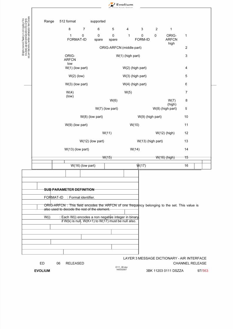
7/11/2019 1. Layer3 Air Interface Messages 0111_06
http://slidepdf.com/reader/full/1-layer3-air-interface-messages-011106 97/562
LAYER 3 MESSAGE DICTIONARY - AIR INTERFACE
ED 06 RELEASED CHANNEL RELEASE
EVOLIUM
0111_06.doc14/03/2007
3BK 11203 0111 DSZZA 97/ 563
Range 512 format supported
8 7 6 5 4 3 2 1
1 0FORMAT-ID
0spare
0spare
1 0 0FORM-ID
ORIG-ARFCN
high
1
ORIG-ARFCN (middle part) 2
ORIG-ARFCN
low
W(1) (high part) 3
W(1) (low part) W(2) (high part) 4
W(2) (low) W(3) (high part) 5
W(3) (low part) W(4) (high part) 6
W(4)(low)
W(5) 7
W(6) W(7)(high)
8
W(7) (low part) W(8) (high part) 9
W(8) (low part) W(9) (high part) 10
W(9) (low part) W(10) 11
W(11) W(12) (high) 12
W(12) (low part) W(13) (high part) 13
W(13) (low part) W(14) 14
W(15) W(16) (high) 15
W(16) (low part) W(17) 16
SUB PARAMETER DEFINITION
FORMAT-ID : Format identifier.
ORIG-ARFCN : This field encodes the ARFCN of one frequency belonging to the set. This value isalso used to decode the rest of the element.
W(i) : Each W(i) encodes a non negative integer in binary.if W(k) is null, W(K+1) to W(17) must be null also.
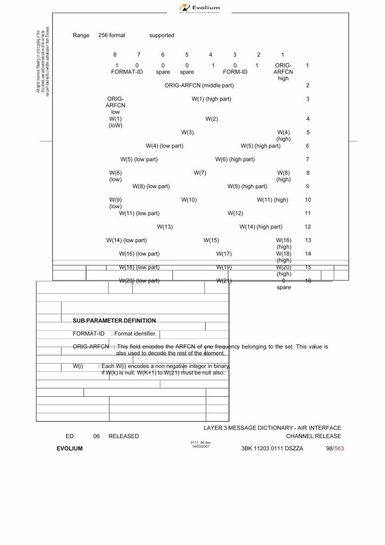
7/11/2019 1. Layer3 Air Interface Messages 0111_06
http://slidepdf.com/reader/full/1-layer3-air-interface-messages-011106 98/562
LAYER 3 MESSAGE DICTIONARY - AIR INTERFACE
ED 06 RELEASED CHANNEL RELEASE
EVOLIUM
0111_06.doc14/03/2007
3BK 11203 0111 DSZZA 98/ 563
Range 256 format supported
8 7 6 5 4 3 2 1
1 0FORMAT-ID
0spare
0spare
1 0 1FORM-ID
ORIG-ARFCN
high
1
ORIG-ARFCN (middle part) 2
ORIG-ARFCN
low
W(1) (high part) 3
W(1)(loW)
W(2) 4
W(3) W(4)(high)
5
W(4) (low part) W(5) (high part) 6
W(5) (low part) W(6) (high part) 7
W(6)(low)
W(7) W(8)(high)
8
W(8) (low part) W(9) (high part) 9
W(9)(low)
W(10) W(11) (high) 10
W(11) (low part) W(12) 11
W(13) W(14) (high part) 12
W(14) (low part) W(15) W(16)(high)
13
W(16) (low part) W(17) W(18)(high)
14
W(18) (low part) W(19) W(20)(high)
15
W(20) (low part) W(21) 0spare
16
SUB PARAMETER DEFINITION
FORMAT-ID : Format identifier.
ORIG-ARFCN : This field encodes the ARFCN of one frequency belonging to the set. This value isalso used to decode the rest of the element.
W(i) : Each W(i) encodes a non negative integer in binary.if W(k) is null, W(K+1) to W(21) must be null also.
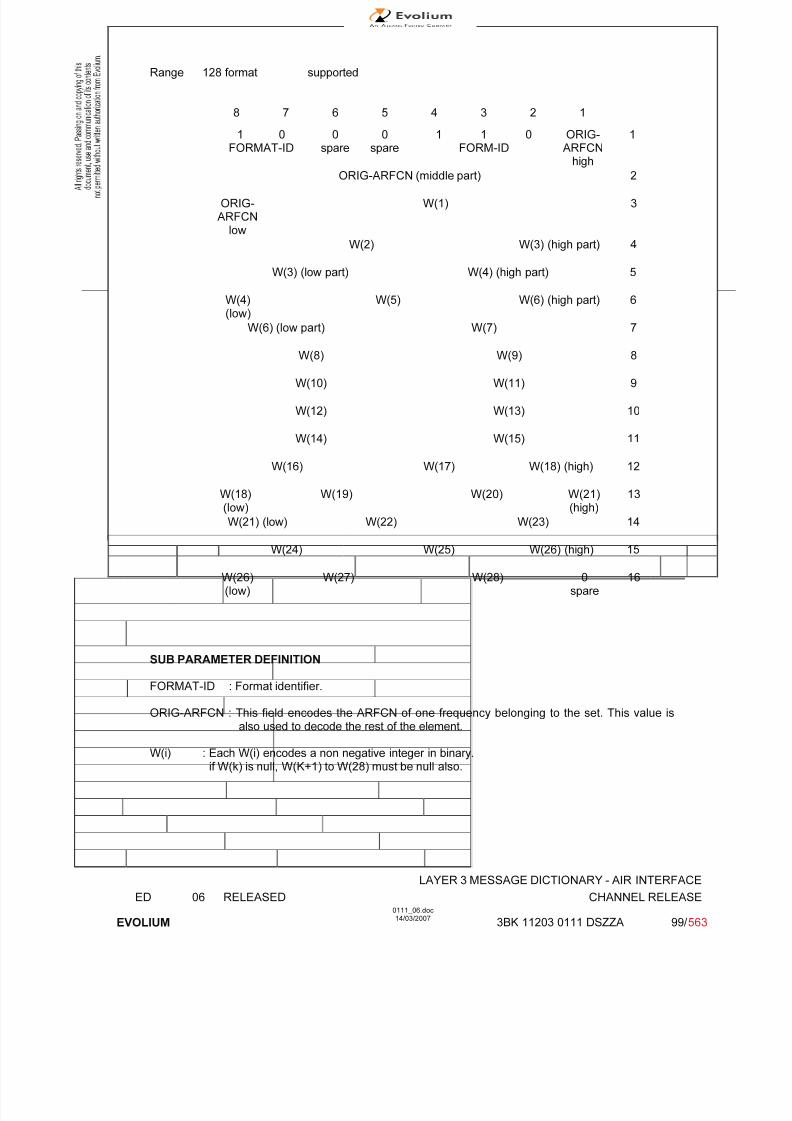
7/11/2019 1. Layer3 Air Interface Messages 0111_06
http://slidepdf.com/reader/full/1-layer3-air-interface-messages-011106 99/562
LAYER 3 MESSAGE DICTIONARY - AIR INTERFACE
ED 06 RELEASED CHANNEL RELEASE
EVOLIUM
0111_06.doc14/03/2007
3BK 11203 0111 DSZZA 99/ 563
Range 128 format supported
8 7 6 5 4 3 2 1
1 0FORMAT-ID
0spare
0spare
1 1 0FORM-ID
ORIG-ARFCN
high
1
ORIG-ARFCN (middle part) 2
ORIG-ARFCN
low
W(1) 3
W(2) W(3) (high part) 4
W(3) (low part) W(4) (high part) 5
W(4)(low)
W(5) W(6) (high part) 6
W(6) (low part) W(7) 7
W(8) W(9) 8
W(10) W(11) 9
W(12) W(13) 10
W(14) W(15) 11
W(16) W(17) W(18) (high) 12
W(18)(low)
W(19) W(20) W(21)(high)
13
W(21) (low) W(22) W(23) 14
W(24) W(25) W(26) (high) 15
W(26)(low)
W(27) W(28) 0spare
16
SUB PARAMETER DEFINITION
FORMAT-ID : Format identifier.
ORIG-ARFCN : This field encodes the ARFCN of one frequency belonging to the set. This value isalso used to decode the rest of the element.
W(i) : Each W(i) encodes a non negative integer in binary.if W(k) is null, W(K+1) to W(28) must be null also.

7/11/2019 1. Layer3 Air Interface Messages 0111_06
http://slidepdf.com/reader/full/1-layer3-air-interface-messages-011106 100/562
LAYER 3 MESSAGE DICTIONARY - AIR INTERFACE
ED 06 RELEASED CHANNEL RELEASE
EVOLIUM
0111_06.doc14/03/2007
3BK 11203 0111 DSZZA 100/ 563
Variable bit map format supported
8 7 6 5 4 3 2 1
1 0FORMAT-ID
0 0 1 1 1FORMAT-ID(continued)
ORIG-ARFC
N
highORIG-ARFCN (middle part)
ORIG-ARFCN
(low)
RRFCN1
RRFCN2
RRFCN3
RRFCN4
RRFCN5
RRFCN6
RRFCN7
: :
RRFCN104
RRFCN105
RRFCN106
RRFCN107
RRFCN108
RRFCN109
RRFCN110
RRFCN
111
Bits 5 and 6 are spare bits in octet 2.
SUB PARAMETER DEFINITION
FORMAT-ID : Format identifier Bitmap 0 format is only supported for GSM 900Variable bit map is only supported for DCS 1800, GSM850 andDCS1900
CA ARFCN N : Cell Allocation Absolute Radio Frequency Channel Number N
CA ARFCN N : "0" not belonging to the cell allocation"1" belonging to the cell allocation
ORIG-ARFCN : This field encodes the ARFCN of one frequency belonging to the set. This value isalso used as the origin of the bit map to generate all the other frequencies.
RRFCN N : Relative radio frequency channel number N- For an RF channel with ARFCN = ORIG-ARFCN + N) mod 1024 belonging to the set,
then RRFCN N bit is coded as '1'.- For an RF channel with ARFCN = (ORIG-ARFCN + N) mod 1024 not belonging to the set,
then RRFCN N bit is coded as '0'.
PARAMETER ORIGIN - ACTION ON PARAMETER
CA ARFCN N, ORIG-ARFCN, RRFCN : values stored in BSC and updated according to systemreconfigurations.

7/11/2019 1. Layer3 Air Interface Messages 0111_06
http://slidepdf.com/reader/full/1-layer3-air-interface-messages-011106 101/562
LAYER 3 MESSAGE DICTIONARY - AIR INTERFACE
ED 06 RELEASED CHANNEL REQUEST
EVOLIUM
0111_06.doc14/03/2007
3BK 11203 0111 DSZZA 101/ 563
6.8 CHANNEL REQUEST
NAME CHANNEL REQUEST
INTERFACE RADIO ABIS A
CHANNEL/ USAGE
RACH
3GPP-REF 44.018
FUNCTION This message is sent in random mode on the RACH. It does not follow the basicformat.
DIRECTION From: MS To: BTS
INFORMATION ELEMENT NAME TYPE COMMENT LENGTH(byte)
INFORMATIONELEMENT
LIST See the next page Unformatted 8bit field
1
IMPLEMENTATION MAXIMUM LENGTH 1
NORMAL SITUATION ABNORMAL SITUATION TIMER
FOLLOWINGEVENT
CHANNEL REQUIRED towards
the BSC
_ _
SPECIFDOC. REF.
Paging and Access Grant Control (ref. [1])Radio and Link Establishment (ref. [2])FBS GPRS - Radio interface - RRM sublayer - PCC (ref. [29])

7/11/2019 1. Layer3 Air Interface Messages 0111_06
http://slidepdf.com/reader/full/1-layer3-air-interface-messages-011106 102/562
LAYER 3 MESSAGE DICTIONARY - AIR INTERFACE
ED 06 RELEASED CHANNEL REQUEST
EVOLIUM
0111_06.doc14/03/2007
3BK 11203 0111 DSZZA 102/ 563
6.8.1 GENERAL DESCRIPTION
BIT DESCRIPTION
8 7 6 5 4 3 2 1
Establ. Random
Cause Reference
SUB PARAMETER DEFINITION
Establishment cause: This information field indicates the reason for requesting the establishment of a connection.This field has a variable length (from 3 bits up to 6 bits).
8 7 6 5 4 3 2 1 MEANING OF ESTABLISHMENT CAUSE.
1 0 1 X X X X X Emergency call.
1 1 0 X X X X X Call Re-establishment. TCH/F was in use, or TCH/H was in use butthe network does not set NECI bit to 1.
0 1 1 0 1 0 X X Call Re-establishment. TCH/H was in use and the network setsNECI bit to 1.
0 1 1 0 1 1 X X Call Re-establishment. TCH/H + TCH/H was in use and the networksets NECI bit to 1.
100
0
000
0
011
0
X01
1
XXX
X
XXX
X
XXX
X
XXX
X
Answer to paging, see Note 2.
1 1 1 X X X X X Originating Call and TCH/F is needed, or originating call, or procedures which can be completed with an SDCCH, and thenetwork does not set NECI bit to 1.
0 1 0 0 X X X X Originating speech call from dual-rate mobile station when TCH/H issufficient and the network sets NECI bit to 1.
0 1 0 1 X X X X Originating data call from dual-rate mobile station when TCH/H issufficient and the network sets NECI bit to 1.
0 0 0 x x x x x Location Updating, and the network does not set the NECI bit to 1.
0 0 0 0 X X X X Location Updating, and the network sets the NECI bit to 1.
0 0 0 1 X X X X Other procedures which can be completed with an SDCCH.e.g.; Short message services, IMSI detach, and the network setsthe NECI bit to 1.
000
111
111
111
111
0XX
X0X
XX0
One phase packet access with request for single timeslot uplinktransmission; one PDCH is needed.
0 1 1 1 0 x x x Single block packet access; one block period on a PDCH is neededfor two phase packet access or other RR signalling purpose.
0 1 1 0 0 1 1 1 LMU establishment (not implemented)
000
111
111
000
000
XX0
X01
011
Reserved for future use.
0 1 1 1 1 1 1 1 Reserved for future use.

7/11/2019 1. Layer3 Air Interface Messages 0111_06
http://slidepdf.com/reader/full/1-layer3-air-interface-messages-011106 103/562
LAYER 3 MESSAGE DICTIONARY - AIR INTERFACE
ED 06 RELEASED CHANNEL REQUEST
EVOLIUM
0111_06.doc14/03/2007
3BK 11203 0111 DSZZA 103/ 563
Note 1: The codings above highlighted in bold are equivalent to those expected from a phase 1 GSMmobile.
Note 2: The coding of CHANNEL REQUEST message (when answering to paging for RR connectionestablishment) is as follows:
Paging Indication MS Capability
Full rate only Dual Rate SDCCH only
Any Channel 100XXXXX 100XXXXX 100XXXXX
SDCCH 0001XXXX 0001XXXX 0001XXXX
TCH/ F 100XXXXX 0010XXXX 0001XXXX
TCH/H or TCH/F 100XXXXX 0011XXXX 0001XXXX
Random reference
This is an unformatted field of variable length from 5 to 2 bits
PARAMETER ORIGIN - ACTION ON PARAMETER.All the establishment cause values are accepted by the BTS which builds a CHANNEL REQUIREDmessage and send it to the BSC (no check is made). The BSC will discard the following CHANNELREQUIRED message:
• a CHANNEL REQUIRED message received with a Random Access Information field (ie.Channel Request content) set to 001X XXXX, 010X XXXX, or 011X XXXX. See reference [25];
• a CHANNEL REQUIRED message with the content “Reserved for future use” (ie. 0110 0xx0,0110 0x01, 0110 0011, or 0111 1111);
• a CHANNEL REQUIRED message with the content 0110 0111 (LMU establishment).

7/11/2019 1. Layer3 Air Interface Messages 0111_06
http://slidepdf.com/reader/full/1-layer3-air-interface-messages-011106 104/562
LAYER 3 MESSAGE DICTIONARY - AIR INTERFACE
ED 06 RELEASED CIPHERING MODE COMMAND
EVOLIUM
0111_06.doc14/03/2007
3BK 11203 0111 DSZZA 104/ 563
6.9 CIPHERING MODE COMMAND
NAME CIPHERING MODE COMMAND
INTERFACE RADIO ABIS A
CHANNEL/ USAGE
SDCCH/FACCH
3GPP-REF 44.018
FUNCTION This message is sent on the main DCCH from the BSC to the MS to indicate thatthe network has started or stopped (3) deciphering and that enciphering anddeciphering shall be started or stopped (3) in the MS, or to indicate that ciphering will not be performed.
DIRECTION From: BSC To: MS
INFORMATION ELEMENT NAME TYPE COMMENT LENGTH(byte)
INFORMATIONELEMENT
LISTHeader Cipher Mode SettingCipher response
M V M V
Note (1)Note (2)
2½½
IMPLEMENTATION MAXIMUM LENGTH 3
NORMAL SITUATION ABNORMAL SITUATION TIMER
FOLLOWINGEVENT Start ciphering and deciphering
at the MS side.Or Stop ciphering (3). -
SPECIFDOC. REF.
Ciphering procedure (ref. [4])
(1) Multiple algorithms supported in GSM phase 2(2) New field for GSM phase 2, set to 0 to phase 1 MSs
(3) Phase 2 MSs only
Timer Control of this procedure is in the MSC not in the BSS.
This message (ciphering mode command) is sent to the MS as User Data of the encryption commandmessage addressed to the BTS. (See 3GPP TS 08.58).

7/11/2019 1. Layer3 Air Interface Messages 0111_06
http://slidepdf.com/reader/full/1-layer3-air-interface-messages-011106 105/562
LAYER 3 MESSAGE DICTIONARY - AIR INTERFACE
ED 06 RELEASED CIPHERING MODE COMMAND
EVOLIUM
0111_06.doc14/03/2007
3BK 11203 0111 DSZZA 105/ 563
6.9.1 GENERAL DESCRIPTION
8 7 6 5 4 3 2 1
0 0 0 0 0 1 1 0
0 0 1 1 0 1 0 1
Cipher Response
Ciphering Mode setting
0 0 0 CR
Algorithm identifier SC
6.9.2 CIPHER MODE SETTING
TYPE: M
DEFINITIONThe purpose of the cipher mode setting information element is to indicate whether stream cipheringshall be started or not. When ciphering is started, it indicates the algorithm to be used (except for
GSM phase 1 MS).
BIT DESCRIPTION
8 7 6 5 4 3 2 1
Algorithm identifier SC
SUB PARAMETER DEFINITION
Algorithm Identifier
If SC = 1 then:
Bits 4 3 20 0 0 Cipher with algorithm A5/10 0 1 Cipher with algorithm A5/20 1 0 Cipher with algorithm A5/3 Not supported in this release0 1 1 Cipher with algorithm A5/4 Not supported in this release1 0 0 Cipher with algorithm A5/5 Not supported in this release1 0 1 Cipher with algorithm A5/6 Not supported in this release1 1 0 Cipher with algorithm A5/7 Not supported in this release1 1 1 Reserved Not supported in this release
Bits 2, 3 and 4 are always set to 0 for GSM Phase 1 MS.
SC bit: "0": No ciphering"1": Start ciphering
PARAMETER ORIGIN - ACTION ON PARAMETER
According to the ciphering procedure scenario, the value 0 is used when no ciphering is needed.
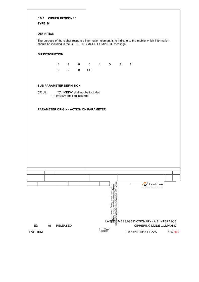
7/11/2019 1. Layer3 Air Interface Messages 0111_06
http://slidepdf.com/reader/full/1-layer3-air-interface-messages-011106 106/562
LAYER 3 MESSAGE DICTIONARY - AIR INTERFACE
ED 06 RELEASED CIPHERING MODE COMMAND
EVOLIUM
0111_06.doc14/03/2007
3BK 11203 0111 DSZZA 106/ 563
6.9.3 CIPHER RESPONSE
TYPE: M
DEFINITION
The purpose of the cipher response information element is to indicate to the mobile which information
should be included in the CIPHERING MODE COMPLETE message.
BIT DESCRIPTION
8 7 6 5 4 3 2 1
0 0 0 CR
SUB PARAMETER DEFINITION
CR bit: "0": IMEISV shall not be included"1": IMEISV shall be included
PARAMETER ORIGIN - ACTION ON PARAMETER

7/11/2019 1. Layer3 Air Interface Messages 0111_06
http://slidepdf.com/reader/full/1-layer3-air-interface-messages-011106 107/562
LAYER 3 MESSAGE DICTIONARY - AIR INTERFACE
ED 06 RELEASED DATA INDICATION
EVOLIUM
0111_06.doc14/03/2007
3BK 11203 0111 DSZZA 107/ 563
6.10 DATA INDICATION
NAME CIPHERING MODE COMPLETE
INTERFACE RADIO ABIS A
CHANNEL/ USAGE
SDCCH/FACCH BTS Transparent
3GPP-REF 44.018 NA
FUNCTION This message is sent on the main DCCH from the Mobile Station to the networkto indicate that enciphering and deciphering has been started or stopped in theMobile Station.
DIRECTION From: MS To: BSC
INFORMATION ELEMENT NAME TYPE COMMENT LENGTH(byte)
INFORMATIONELEMENT
LISTHeader Mobile Equipment Identity O TLV Note (1)
211
IMPLEMENTATION MAXIMUM LENGTH 2-12
NORMAL SITUATION ABNORMAL SITUATION TIMER
FOLLOWINGEVENT
- - -
SPECIFDOC. REF.
Ciphering procedure (ref. [4])
(1) Set if CR field in Ciphering mode command was set to 1. GSM Phase 2 Mobiles only. Thiselement is only sent to the MSC if received from the MS. (See 3GPP TS 08.08).
Timer in MSC is stopped on reception of this message.
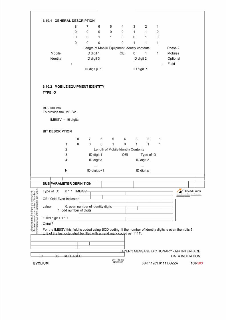
7/11/2019 1. Layer3 Air Interface Messages 0111_06
http://slidepdf.com/reader/full/1-layer3-air-interface-messages-011106 108/562
LAYER 3 MESSAGE DICTIONARY - AIR INTERFACE
ED 06 RELEASED DATA INDICATION
EVOLIUM
0111_06.doc14/03/2007
3BK 11203 0111 DSZZA 108/ 563
6.10.1 GENERAL DESCRIPTION
8 7 6 5 4 3 2 1
0 0 0 0 0 1 1 0
0 0 1 1 0 0 1 0
0 0 0 1 0 1 1 1
Length of Mobile Equipment Identity contents Phase 2Mobile ID digit 1 OEI 0 1 1 Mobiles
Identity ID digit 3 ID digit 2 Optional
: : Field
ID digit p+1 ID digit P
6.10.2 MOBILE EQUIPMENT IDENTITY
TYPE: O
DEFINITIONTo provide the IMEISV.
IMEISV = 16 digits
BIT DESCRIPTION
8 7 6 5 4 3 2 1
1 0 0 0 1 0 1 1 1
2 Length of Mobile Identity Contents
3 ID digit 1 OEI Type of ID
4 ID digit 3 ID digit 2
... ...
N ID digit p+1 ID digit p
SUB PARAMETER DEFINITION
Type of ID: 0 1 1 IMEISV
OEI: Odd Even Indicator
value 0: even number of identity digits1: odd number of digits
Filled digit 1 1 1 1
Octet 3
For the IMEISV this field is coded using BCD coding. If the number of identity digits is even then bits 5to 8 of the last octet shall be filled with an end mark coded as '1111'.
7/11/2019 1. Layer3 Air Interface Messages 0111_06
http://slidepdf.com/reader/full/1-layer3-air-interface-messages-011106 109/562
LAYER 3 MESSAGE DICTIONARY - AIR INTERFACE
ED 06 RELEASED DATA INDICATION
EVOLIUM
0111_06.doc14/03/2007
3BK 11203 0111 DSZZA 109/ 563
PARAMETER ORIGIN - ACTION ON PARAMETER
BSC and BTS are transparent to this parameter.
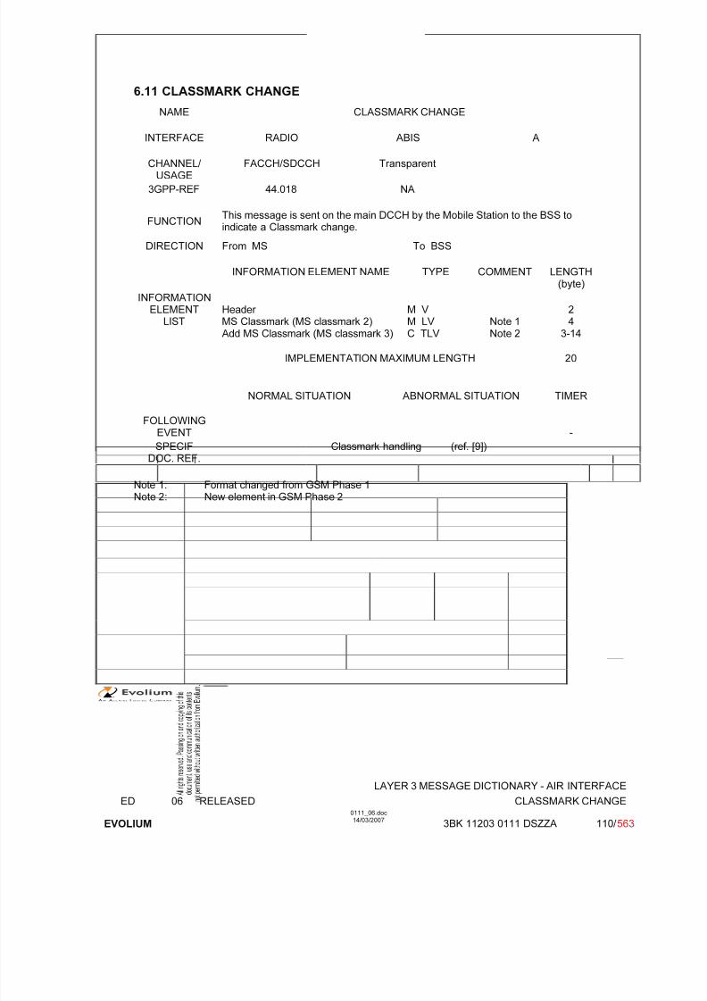
7/11/2019 1. Layer3 Air Interface Messages 0111_06
http://slidepdf.com/reader/full/1-layer3-air-interface-messages-011106 110/562
LAYER 3 MESSAGE DICTIONARY - AIR INTERFACE
ED 06 RELEASED CLASSMARK CHANGE
EVOLIUM
0111_06.doc14/03/2007
3BK 11203 0111 DSZZA 110/ 563
6.11 CLASSMARK CHANGE
NAME CLASSMARK CHANGE
INTERFACE RADIO ABIS A
CHANNEL/ USAGE
FACCH/SDCCH Transparent
3GPP-REF 44.018 NA
FUNCTIONThis message is sent on the main DCCH by the Mobile Station to the BSS toindicate a Classmark change.
DIRECTION From MS To BSS
INFORMATION ELEMENT NAME TYPE COMMENT LENGTH(byte)
INFORMATION
ELEMENTLIST
Header MS Classmark (MS classmark 2)Add MS Classmark (MS classmark 3)
M V M LV C TLV
Note 1Note 2
24
3-14
IMPLEMENTATION MAXIMUM LENGTH 20
NORMAL SITUATION ABNORMAL SITUATION TIMER
FOLLOWINGEVENT -
SPECIF
DOC. REF.
Classmark handling (ref. [9])
Note 1: Format changed from GSM Phase 1Note 2: New element in GSM Phase 2
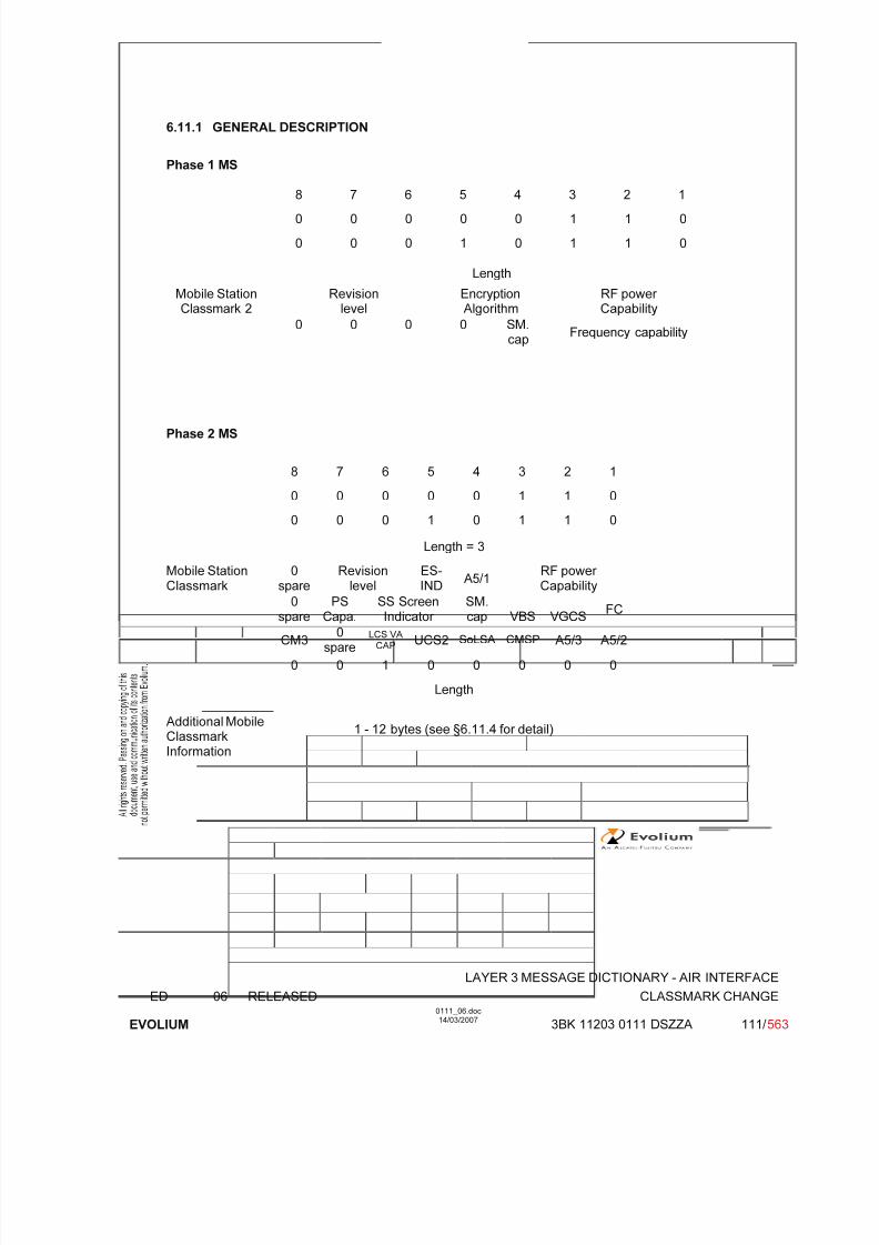
7/11/2019 1. Layer3 Air Interface Messages 0111_06
http://slidepdf.com/reader/full/1-layer3-air-interface-messages-011106 111/562
LAYER 3 MESSAGE DICTIONARY - AIR INTERFACE
ED 06 RELEASED CLASSMARK CHANGE
EVOLIUM
0111_06.doc14/03/2007
3BK 11203 0111 DSZZA 111/ 563
6.11.1 GENERAL DESCRIPTION
Phase 1 MS
8 7 6 5 4 3 2 1
0 0 0 0 0 1 1 0
0 0 0 1 0 1 1 0
Length
Mobile StationClassmark 2
Revisionlevel
EncryptionAlgorithm
RF power Capability
0 0 0 0 SM.cap
Frequency capability
Phase 2 MS
8 7 6 5 4 3 2 1
0 0 0 0 0 1 1 0
0 0 0 1 0 1 1 0
Length = 3
Mobile StationClassmark 0spare Revisionlevel ES-IND A5/1 RF power Capability
0spare
PSCapa.
SS ScreenIndicator
SM.cap VBS VGCS
FC
CM30
spareLCS VA
CAP UCS2 SoLSA CMSP A5/3 A5/2
0 0 1 0 0 0 0 0
Length
Additional MobileClassmarkInformation
1 - 12 bytes (see §6.11.4 for detail)

7/11/2019 1. Layer3 Air Interface Messages 0111_06
http://slidepdf.com/reader/full/1-layer3-air-interface-messages-011106 112/562
LAYER 3 MESSAGE DICTIONARY - AIR INTERFACE
ED 06 RELEASED CLASSMARK CHANGE
EVOLIUM
0111_06.doc14/03/2007
3BK 11203 0111 DSZZA 112/ 563
6.11.2 MS CLASSMARK 2 - GSM Phase 1
TYPE: M
DEFINITION Defines certain attributes of the Mobile Station equipment in use on a particular transaction.
BIT DESCRIPTION
8 7 6 5 4 3 2 1
Length 1
Revisionlevel
EncryptionAlgorithm
RF power Capability
2
0 0 0 0 SM.cap
Frequency capability 3
Bits 8-5 of octet 3 spare set to 0.
SUB PARAMETER DEFINITION
Octet 2Bits 8 7 6 Revision level 0 0 0 Reserved for phase 1.
All other values reserved Bits 5 4 Encryption Algorithm 0 0 algorithm A5/1
All other values reserved.Bits 3 2 1RF Power capability
GSM900 0 0 0 class 10 0 1 class 20 1 0 class 3
0 1 1 class 41 0 0 class 5
All other values reservedDCS1800 0 0 0 class 1
0 0 1 class 2All other values reserved
DCS1900 0 0 0 class 10 0 1 class 20 1 0 class 3
All other values reserved
Octet 3Bit 4
SM Capability 0 short message capability not present1 short message capability present
Bits 3 2 1FC Frequency Capability 0 0 0 Band no 0
Other values reserved.
7/11/2019 1. Layer3 Air Interface Messages 0111_06
http://slidepdf.com/reader/full/1-layer3-air-interface-messages-011106 113/562
LAYER 3 MESSAGE DICTIONARY - AIR INTERFACE
ED 06 RELEASED CLASSMARK CHANGE
EVOLIUM
0111_06.doc14/03/2007
3BK 11203 0111 DSZZA 113/ 563
PARAMETER ORIGIN - ACTION ON PARAMETER
This is the MS classmark 2 as sent by a phase 1 MS.The BSC takes this information in order to have the MS power capability for the power controlalgorithm.Note: The BSC will decode the two octets of this IE value as if they were the two first octets of a
phase 2 MS classmark 2 IE value.
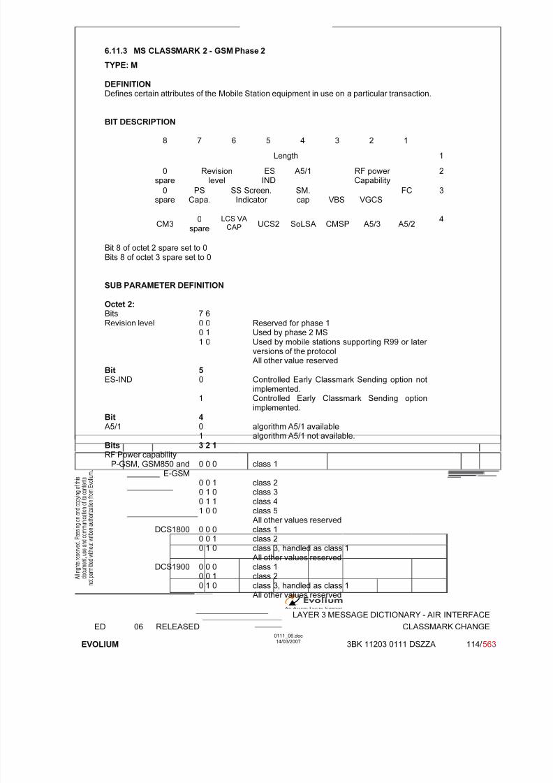
7/11/2019 1. Layer3 Air Interface Messages 0111_06
http://slidepdf.com/reader/full/1-layer3-air-interface-messages-011106 114/562
LAYER 3 MESSAGE DICTIONARY - AIR INTERFACE
ED 06 RELEASED CLASSMARK CHANGE
EVOLIUM
0111_06.doc14/03/2007
3BK 11203 0111 DSZZA 114/ 563
6.11.3 MS CLASSMARK 2 - GSM Phase 2
TYPE: M
DEFINITION Defines certain attributes of the Mobile Station equipment in use on a particular transaction.
BIT DESCRIPTION
8 7 6 5 4 3 2 1
Length 1
0spare
Revisionlevel
ESIND
A5/1 RF power Capability
2
0spare
PSCapa.
SS Screen.Indicator
SM.cap VBS VGCS
FC 3
CM30
spare
LCS VA CAP UCS2 SoLSA CMSP A5/3 A5/2
4
Bit 8 of octet 2 spare set to 0Bits 8 of octet 3 spare set to 0
SUB PARAMETER DEFINITION
Octet 2:Bits 7 6Revision level 0 0 Reserved for phase 1
0 1 Used by phase 2 MS 1 0 Used by mobile stations supporting R99 or later
versions of the protocol
All other value reservedBit 5ES-IND 0 Controlled Early Classmark Sending option not
implemented.1 Controlled Early Classmark Sending option
implemented.Bit 4A5/1 0 algorithm A5/1 available
1 algorithm A5/1 not available.Bits 3 2 1RF Power capability
P-GSM, GSM850 andE-GSM
0 0 0 class 1
0 0 1 class 20 1 0 class 30 1 1 class 41 0 0 class 5
All other values reservedDCS1800 0 0 0 class 1
0 0 1 class 20 1 0 class 3, handled as class 1
All other values reservedDCS1900 0 0 0 class 1
0 0 1 class 20 1 0 class 3, handled as class 1
All other values reserved
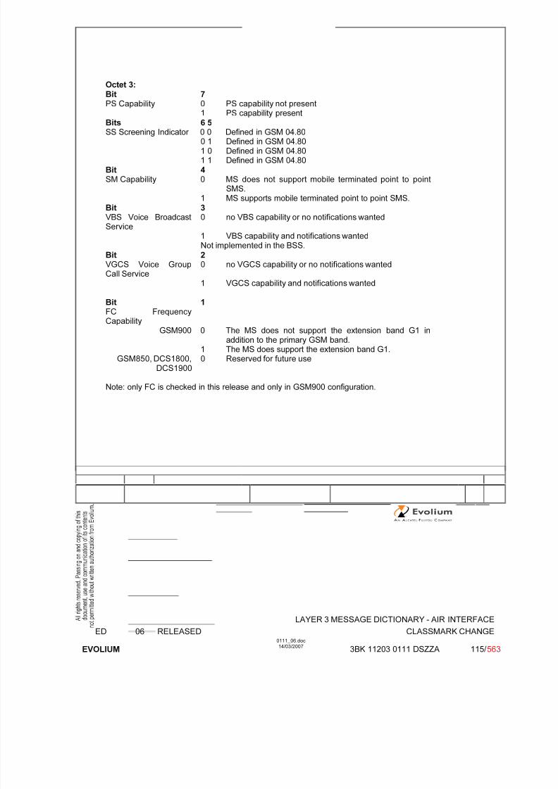
7/11/2019 1. Layer3 Air Interface Messages 0111_06
http://slidepdf.com/reader/full/1-layer3-air-interface-messages-011106 115/562
LAYER 3 MESSAGE DICTIONARY - AIR INTERFACE
ED 06 RELEASED CLASSMARK CHANGE
EVOLIUM
0111_06.doc14/03/2007
3BK 11203 0111 DSZZA 115/ 563
Octet 3:Bit 7PS Capability 0 PS capability not present
1 PS capability present
Bits 6 5SS Screening Indicator 0 0 Defined in GSM 04.80
0 1 Defined in GSM 04.801 0 Defined in GSM 04.801 1 Defined in GSM 04.80
Bit 4SM Capability 0 MS does not support mobile terminated point to point
SMS.1 MS supports mobile terminated point to point SMS.
Bit 3VBS Voice BroadcastService
0 no VBS capability or no notifications wanted
1 VBS capability and notifications wanted
Not implemented in the BSS.Bit 2VGCS Voice GroupCall Service
0 no VGCS capability or no notifications wanted
1 VGCS capability and notifications wanted
Bit 1FC FrequencyCapability
GSM900 0 The MS does not support the extension band G1 inaddition to the primary GSM band.
1 The MS does support the extension band G1.GSM850, DCS1800,
DCS19000 Reserved for future use
Note: only FC is checked in this release and only in GSM900 configuration.

7/11/2019 1. Layer3 Air Interface Messages 0111_06
http://slidepdf.com/reader/full/1-layer3-air-interface-messages-011106 116/562
LAYER 3 MESSAGE DICTIONARY - AIR INTERFACE
ED 06 RELEASED CLASSMARK CHANGE
EVOLIUM
0111_06.doc14/03/2007
3BK 11203 0111 DSZZA 116/ 563
Octet 4Bit 8CM3 Classmark 3 0 No additional MS capability
1 Additional MS capabilities are described in the MSClassmark 3 information element.
Bit 6LCS VA capability 0 LCS value added location request notification capability not
supported1 LCS value added location request notification capabilitysupported
Not implemented in the BSS.Bit 5UCS2 treatment 0 the ME has a preference for the default alphabet (defined in
GSM 03.38) over UCS21 the ME has no preference between the use of the default
alphabet and the use of UCS2.Not implemented in the BSS.
Bit 4SoLSA 0 The ME does not support SoLSA
1 The ME supports SoLSA.
Bit 3CMSP: CM Service Prompt 0 "Network initiated MO CM connection request" not supported1 "Network initiated MO CM connection request" supported for
at least one CM protocol.Not implemented in the BSS.
Bit 2A5/3 algorithm supported 0 A5/3 not available
1 A5/3 available
Bit 1A5/2 algorithm supported 0 A5/2 not available
1 A5/2 availableNote: only A5/2 is checked in this release.
PARAMETER ORIGIN - ACTION ON PARAMETER
The BSC takes this information in order to have the MS power capability for the power controlalgorithm, the MS frequency capability and the MS ciphering capability.Additional mobile info can be obtained by invoking the classmark interrogation procedure.

7/11/2019 1. Layer3 Air Interface Messages 0111_06
http://slidepdf.com/reader/full/1-layer3-air-interface-messages-011106 117/562
LAYER 3 MESSAGE DICTIONARY - AIR INTERFACE
ED 06 RELEASED CLASSMARK CHANGE
EVOLIUM
0111_06.doc14/03/2007
3BK 11203 0111 DSZZA 117/ 563
6.11.4 MS CLASSMARK 3
TYPE: C
DEFINITION Defines certain attributes of the Mobile Station equipment in use on a particular transaction.
BIT DESCRIPTION
8 7 6 5 4 3 2 1
0 0 1 0 0 0 0 0 1
Length 2
Classmark 3 Value part
(See CSN.1 description below)3 - 14
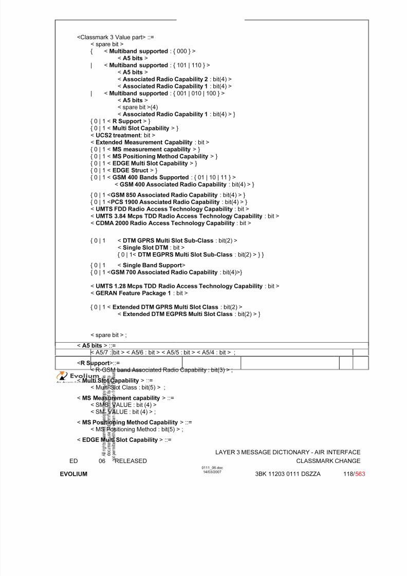
7/11/2019 1. Layer3 Air Interface Messages 0111_06
http://slidepdf.com/reader/full/1-layer3-air-interface-messages-011106 118/562
LAYER 3 MESSAGE DICTIONARY - AIR INTERFACE
ED 06 RELEASED CLASSMARK CHANGE
EVOLIUM
0111_06.doc14/03/2007
3BK 11203 0111 DSZZA 118/ 563
<Classmark 3 Value part> ::=< spare bit >{ < Multiband supported : { 000 } >
< A5 bits >| < Multiband supported : { 101 | 110 } >
< A5 bits >< Associated Radio Capability 2 : bit(4) >
< Associated Radio Capability 1 : bit(4) >| < Multiband supported : { 001 | 010 | 100 } >< A5 bits >< spare bit >(4)< Associated Radio Capability 1 : bit(4) > }
{ 0 | 1 < R Support > }{ 0 | 1 < Multi Slot Capability > }
< UCS2 treatment: bit >< Extended Measurement Capability : bit >{ 0 | 1 < MS measurement capability > }{ 0 | 1 < MS Positioning Method Capability > }{ 0 | 1 < EDGE Multi Slot Capability > }{ 0 | 1 < EDGE Struct > }
{ 0 | 1 < GSM 400 Bands Supported : { 01 | 10 | 11 } >< GSM 400 Associated Radio Capability : bit(4) > }
{ 0 | 1 <GSM 850 Associated Radio Capability : bit(4) > }{ 0 | 1 <PCS 1900 Associated Radio Capability : bit(4) > }< UMTS FDD Radio Access Technology Capability : bit >
< UMTS 3.84 Mcps TDD Radio Access Technology Capability : bit >< CDMA 2000 Radio Access Technology Capability : bit >
{ 0 | 1 < DTM GPRS Multi Slot Sub-Class : bit(2) >< Single Slot DTM : bit >{ 0 | 1< DTM EGPRS Multi Slot Sub-Class : bit(2) > } }
{ 0 | 1 < Single Band Support>{ 0 | 1 <GSM 700 Associated Radio Capability : bit(4)>}
< UMTS 1.28 Mcps TDD Radio Access Technology Capability : bit >< GERAN Feature Package 1 : bit >
{ 0 | 1 < Extended DTM GPRS Multi Slot Class : bit(2) >< Extended DTM EGPRS Multi Slot Class : bit(2) > }
< spare bit > ;
< A5 bits > ::=
< A5/7 : bit > < A5/6 : bit > < A5/5 : bit > < A5/4 : bit > ;<R Support>::=
< R-GSM band Associated Radio Capability : bit(3) > ;
< Multi Slot Capability > ::=< Multi Slot Class : bit(5) > ;
< MS Measurement capability > ::=< SMS_VALUE : bit (4) >< SM_VALUE : bit (4) > ;
< MS Positioning Method Capability > ::=< MS Positioning Method : bit(5) > ;
< EDGE Multi Slot Capability > ::=

7/11/2019 1. Layer3 Air Interface Messages 0111_06
http://slidepdf.com/reader/full/1-layer3-air-interface-messages-011106 119/562
LAYER 3 MESSAGE DICTIONARY - AIR INTERFACE
ED 06 RELEASED CLASSMARK CHANGE
EVOLIUM
0111_06.doc14/03/2007
3BK 11203 0111 DSZZA 119/ 563
< EDGE Multi Slot Class : bit(5) > ;
<EDGE Struct> : :=< Modulation Capability : bit >{ 0 | 1 < EDGE RF Power Capability 1: bit(2) > }{ 0 | 1 < EDGE RF Power Capability 2: bit(2) > }
< Single Band Support > ::=
< GSM Band : bit (4) > ;
SUB PARAMETER DEFINITION
Multiband Supported (3 bit field)
Band 1 supported (third bit of the field)Bit 3: 0 P-GSM not supported
1 P-GSM supported
Band 2 supported (second bit of the field)Bit 2: 0 E-GSM or R-GSM not supported
1 E-GSM or R-GSM supported
Band 3 supported (first bit of the field)Bit 1: 0 DCS 1800 not supported
1 DCS 1800 supported
Note: The indication of support of P-GSM band or E-GSM or R-GSM band is mutuallyexclusive. For single band mobile station all bits are set to 0.
A5/4 (1 bit field) 0 Encryption algorithm A5/4 not available1 Encryption algorithm A5/4 available
Not implemented in the BSS.
A5/5 (1 bit field) 0 Encryption algorithm A5/5 not available1 Encryption algorithm A5/5 available
Not implemented in the BSS.
A5/6 (1 bit field) 0 Encryption algorithm A5/6 not available1 Encryption algorithm A5/6 available
Not implemented in the BSS.
A5/7 (1 bit field) 0 Encryption algorithm A5/7 not available1 Encryption algorithm A5/7 available
Not implemented in the BSS.
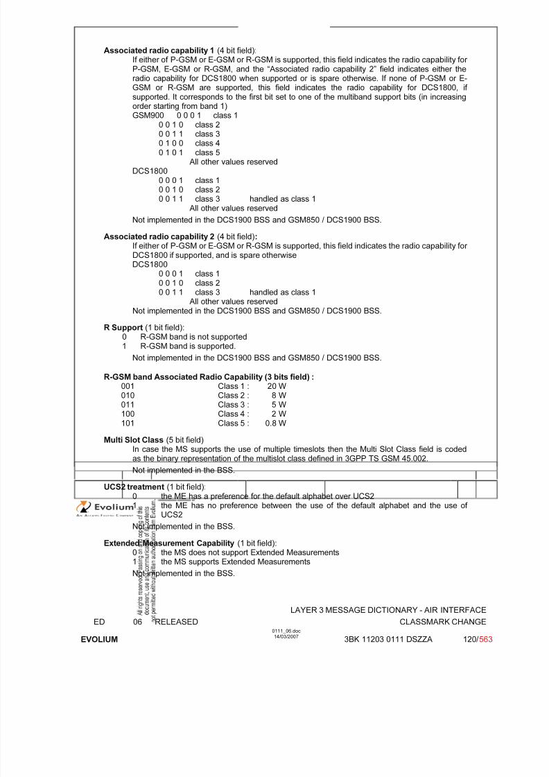
7/11/2019 1. Layer3 Air Interface Messages 0111_06
http://slidepdf.com/reader/full/1-layer3-air-interface-messages-011106 120/562
LAYER 3 MESSAGE DICTIONARY - AIR INTERFACE
ED 06 RELEASED CLASSMARK CHANGE
EVOLIUM
0111_06.doc14/03/2007
3BK 11203 0111 DSZZA 120/ 563
Associated radio capability 1 (4 bit field):If either of P-GSM or E-GSM or R-GSM is supported, this field indicates the radio capability for P-GSM, E-GSM or R-GSM, and the “Associated radio capability 2” field indicates either theradio capability for DCS1800 when supported or is spare otherwise. If none of P-GSM or E-GSM or R-GSM are supported, this field indicates the radio capability for DCS1800, if supported. It corresponds to the first bit set to one of the multiband support bits (in increasingorder starting from band 1)
GSM900 0 0 0 1 class 10 0 1 0 class 20 0 1 1 class 30 1 0 0 class 40 1 0 1 class 5
All other values reservedDCS1800
0 0 0 1 class 10 0 1 0 class 20 0 1 1 class 3 handled as class 1
All other values reserved
Not implemented in the DCS1900 BSS and GSM850 / DCS1900 BSS.
Associated radio capability 2 (4 bit field):If either of P-GSM or E-GSM or R-GSM is supported, this field indicates the radio capability for DCS1800 if supported, and is spare otherwiseDCS1800
0 0 0 1 class 10 0 1 0 class 20 0 1 1 class 3 handled as class 1
All other values reservedNot implemented in the DCS1900 BSS and GSM850 / DCS1900 BSS.
R Support (1 bit field):0 R-GSM band is not supported1 R-GSM band is supported.
Not implemented in the DCS1900 BSS and GSM850 / DCS1900 BSS.
R-GSM band Associated Radio Capability (3 bits field) :001 Class 1 : 20 W010 Class 2 : 8 W011 Class 3 : 5 W100 Class 4 : 2 W101 Class 5 : 0.8 W
Multi Slot Class (5 bit field)In case the MS supports the use of multiple timeslots then the Multi Slot Class field is codedas the binary representation of the multislot class defined in 3GPP TS GSM 45.002.
Not implemented in the BSS.
UCS2 treatment (1 bit field):0 the ME has a preference for the default alphabet over UCS21 the ME has no preference between the use of the default alphabet and the use of
UCS2
Not implemented in the BSS.
Extended Measurement Capability (1 bit field):0 the MS does not support Extended Measurements1 the MS supports Extended Measurements
Not implemented in the BSS.

7/11/2019 1. Layer3 Air Interface Messages 0111_06
http://slidepdf.com/reader/full/1-layer3-air-interface-messages-011106 121/562
LAYER 3 MESSAGE DICTIONARY - AIR INTERFACE
ED 06 RELEASED CLASSMARK CHANGE
EVOLIUM
0111_06.doc14/03/2007
3BK 11203 0111 DSZZA 121/ 563
SMS_VALUE (Switch-Measure-Switch) (4 bit field):The SMS field indicates the time needed for the mobile station to switch from one radiochannel to another, perform a neighbour cell power measurement, and the switch from thatradio channel to another radio channel.
Bits 4 3 2 10 0 0 0 1/4 timeslot (~144 microseconds)
0 0 0 1 2/4 timeslot (~288 microseconds)0 0 1 0 3/4 timeslot (~433 microseconds). . .1 1 1 1 16/4 timeslot (~2307 microseconds)
Not implemented in the BSS.
SM_VALUE (Switch-Measure) (4 bit field):The SM field indicates the time needed for the mobile station to switch from one radio channelto another and perform a neighbour cell power measurement.
Bits 4 3 2 10 0 0 0 1/4 timeslot (~144 microseconds)0 0 0 1 2/4 timeslot (~288 microseconds)
0 0 1 0 3/4 timeslot (~433 microseconds). . .1 1 1 1 16/4 timeslot (~2307 microseconds)
Not implemented in the BSS.
MS Positioning Method Capability (1 bit field):This bit indicates whether the MS supports Positioning Method or not for the provision of Location Services.
Not implemented in the BSS.
MS Positioning Method (5 bit field):This field indicates the Positioning Method(s) supported by the mobile station.
- MS assisted E-OTD
Bit 5: 0 MS assisted E-OTD not supported1 MS assisted E-OTD supported
Not implemented in the BSS.- MS based E-OTD
Bit 4: 0 MS based E-OTD not supported1 MS based E-OTD supported
Not implemented in the BSS.- MS assisted GPS
Bit 3: 0 MS assisted GPS not supported1 MS assisted GPS supported
- MS based GPSBit 2: 0 MS based GPS not supported
1 MS based GPS supported- MS conventional GPS
Bit 1: 0 conventional GPS not supported1 conventional GPS supported
EDGE Multi Slot class (5 bit field):In case the EDGE MS supports the use of multiple timeslots and the number of supportedtime slots is different from number of time slots supported for GMSK then the EDGE Multi Slotclass field is included and is coded as the binary representation of the multislot class definedin 3GPP TS 45.002.
Not implemented in the BSS.
Modulation Capability (1 bit field):

7/11/2019 1. Layer3 Air Interface Messages 0111_06
http://slidepdf.com/reader/full/1-layer3-air-interface-messages-011106 122/562
LAYER 3 MESSAGE DICTIONARY - AIR INTERFACE
ED 06 RELEASED CLASSMARK CHANGE
EVOLIUM
0111_06.doc14/03/2007
3BK 11203 0111 DSZZA 122/ 563
Modulation Capability field indicates the supported modulation scheme by MS in addition toGMSK
0 8-PSK supported for downlink reception only1 8-PSK supported for uplink transmission and downlink reception
Not implemented in the BSS.
EDGE RF Power Capability 1 (2 bit field)
If 8-PSK is supported for both uplink and downlink, the EDGE RF Power Capability 1 fieldindicates the radio capability for GSM400, GSM700,GSM900 and GSM850.
Not implemented in the BSS.
EDGE RF Power Capability 2 (2 bit field)If 8-PSK is supported for both uplink and downlink, the EDGE RF Power Capability 2 fieldindicates the radio capability for DCS1800 or DCS1900 if supported, and is not includedotherwise.
Not implemented in the BSS.
GSM 400 Bands Supported (2 bit field)Bits 2 1
0 1 GSM 480 supported, GSM 450 not supported
1 0 GSM 450 supported, GSM 480 not supported1 1 GSM 450 supported, GSM 480 supported
Not implemented in the BSS.
GSM 400 Associated Radio Capability (4 bit field)If either GSM 450 or GSM 480 or both is supported, the GSM 400 Associated RadioCapability field indicates the radio capability for GSM 450 and/or GSM 480.
Not implemented in the BSS.
GSM 850 Associated Radio Capability (4 bit field)This field indicates whether GSM 850 band is supported and its associated radio capability.Bits 3 2 1
0 0 1 Class 1: 20 W
0 1 0 Class 2: 8 W0 1 1 Class 3: 5 W1 0 0 Class 4: 2 W1 0 1 Class 5: 0.8 W
PCS 1900 Associated Radio Capability (4 bit field)This field indicates whether DCS 1900 band is supported and its associated radio capability.Bits 3 2 1
0 0 1 Class 1: 1 W0 1 0 Class 2: 0.25 W0 1 1 Class 3: 2 W handled as class 1
UMTS FDD Radio Access Technology Capability (1 bit field)
0 UMTS FDD not supported1 UMTS FDD supported
UMTS 3.84 Mcps TDD Radio Access Technology Capability (1 bit field)
0 UMTS 3.84 Mcps TDD not supported
1 UMTS 3.84 Mcps TDD supported
Not implemented in the BSS.
CDMA 2000 Radio Access Technology Capability (1 bit field)0 CDMA2000 not supported1 CDMA2000 supported
Not implemented in the BSS.

7/11/2019 1. Layer3 Air Interface Messages 0111_06
http://slidepdf.com/reader/full/1-layer3-air-interface-messages-011106 123/562
LAYER 3 MESSAGE DICTIONARY - AIR INTERFACE
ED 06 RELEASED CLASSMARK CHANGE
EVOLIUM
0111_06.doc14/03/2007
3BK 11203 0111 DSZZA 123/ 563
DTM GPRS Multi Slot -Class (2 bit field)0 0 Unused. If received, the network shall interpret this as ‘01’0 1 Sub-Class 5 supported1 0 Sub-Class 9 supported1 1 Multislot class 11 supported
Not checked by the BSS.
Single Slot DTM (1 bit field)
This field indicates whether the MS supports single slot DTM operation (see 3GPP TS 43.055 [87]). Itis coded as follows:
Bit 10 Single Slot DTM not supported1 Single Slot DTM supported
Not checked by the BSS.
DTM EGPRS Multi Slot Sub-Class (2 bit field)This field indicates the EGPRS DTM capabilities of the MS. The DTM EGPRS Multi Slot Sub-
Class is independent from the Multi Slot Capabilities field. This field shall be included only if the mobile station supports EGPRS DTM. This field is coded as the DTM GPRS Multi SlotSub-Class field.
Not checked by the BSS.
Single Band Support (4 bit field):This field is sent in case of UMTS to GSM handover if the MS supports UMTS and one andonly one GSM band with the exception of R-GSM. It indicates the GSM band supported by theMS.Bits 4 3 2 1
0 0 0 0 E-GSM is supported
0 0 0 1 P-GSM is supported0 0 1 0 DCS1800 is supported0 0 1 1 GSM450 is supported0 1 0 0 GSM480 is supported0 1 0 1 GSM850 is supported0 1 1 0 PCS1900 is supported
Not checked by the BSS.GSM Band (4 bit field)Bits4 3 2 10 0 0 0 E-GSM is supported0 0 0 1 P-GSM is supported0 0 1 0 GSM 1800 is supported
0 0 1 1 GSM 450 is supported0 1 0 0 GSM 480 is supported0 1 0 1 GSM 850 is supported0 1 1 0 GSM 1900 is supported0 1 1 1 GSM 700 is supportedAll other values are reserved for future use.
Note When this field is received, the associated RF power capability is found in Classmark 1 or 2.
Not checked by the BSS.
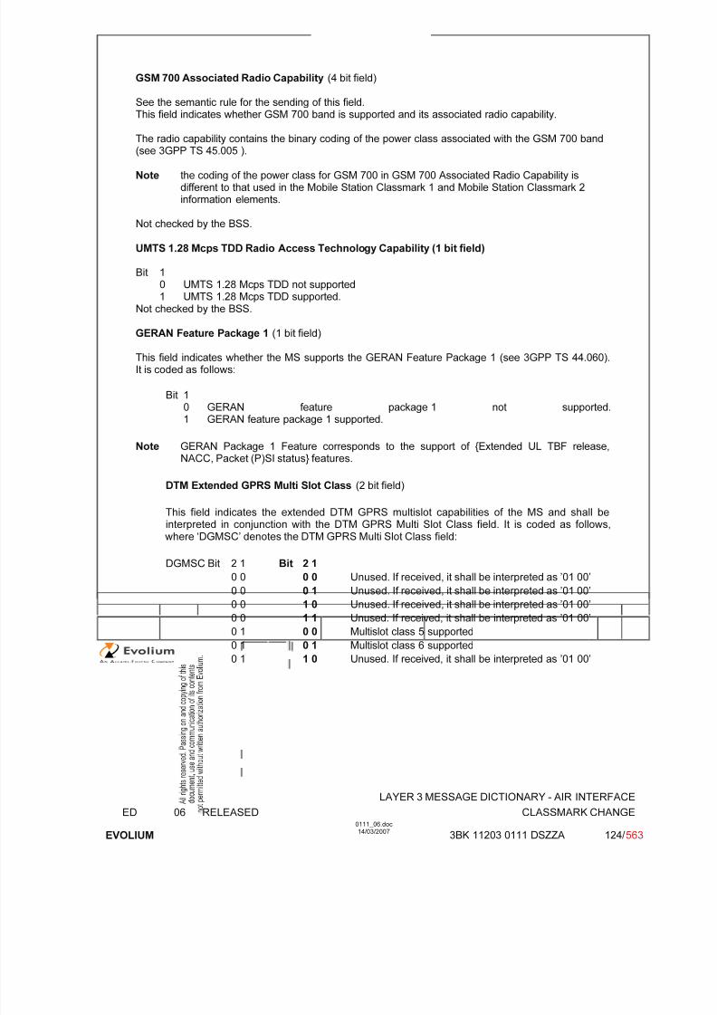
7/11/2019 1. Layer3 Air Interface Messages 0111_06
http://slidepdf.com/reader/full/1-layer3-air-interface-messages-011106 124/562
LAYER 3 MESSAGE DICTIONARY - AIR INTERFACE
ED 06 RELEASED CLASSMARK CHANGE
EVOLIUM
0111_06.doc14/03/2007
3BK 11203 0111 DSZZA 124/ 563
GSM 700 Associated Radio Capability (4 bit field)
See the semantic rule for the sending of this field.This field indicates whether GSM 700 band is supported and its associated radio capability.
The radio capability contains the binary coding of the power class associated with the GSM 700 band
(see 3GPP TS 45.005 ).
Note the coding of the power class for GSM 700 in GSM 700 Associated Radio Capability isdifferent to that used in the Mobile Station Classmark 1 and Mobile Station Classmark 2information elements.
Not checked by the BSS.
UMTS 1.28 Mcps TDD Radio Access Technology Capability (1 bit field)
Bit 10 UMTS 1.28 Mcps TDD not supported1 UMTS 1.28 Mcps TDD supported.
Not checked by the BSS.
GERAN Feature Package 1 (1 bit field)
This field indicates whether the MS supports the GERAN Feature Package 1 (see 3GPP TS 44.060).It is coded as follows:
Bit 10 GERAN feature package 1 not supported.1 GERAN feature package 1 supported.
Note GERAN Package 1 Feature corresponds to the support of {Extended UL TBF release,NACC, Packet (P)SI status} features.
DTM Extended GPRS Multi Slot Class (2 bit field)
This field indicates the extended DTM GPRS multislot capabilities of the MS and shall beinterpreted in conjunction with the DTM GPRS Multi Slot Class field. It is coded as follows, where ‘DGMSC’ denotes the DTM GPRS Multi Slot Class field:
DGMSC Bit 2 1 Bit 2 1
0 0 0 0 Unused. If received, it shall be interpreted as ’01 00’
0 0 0 1 Unused. If received, it shall be interpreted as ’01 00’
0 0 1 0 Unused. If received, it shall be interpreted as ’01 00’
0 0 1 1 Unused. If received, it shall be interpreted as ’01 00’
0 1 0 0 Multislot class 5 supported
0 1 0 1 Multislot class 6 supported
0 1 1 0 Unused. If received, it shall be interpreted as ’01 00’
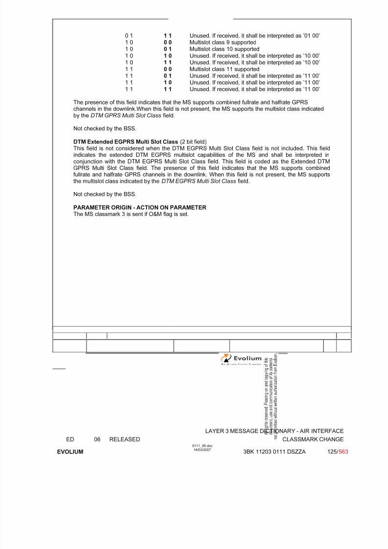
7/11/2019 1. Layer3 Air Interface Messages 0111_06
http://slidepdf.com/reader/full/1-layer3-air-interface-messages-011106 125/562
LAYER 3 MESSAGE DICTIONARY - AIR INTERFACE
ED 06 RELEASED CLASSMARK CHANGE
EVOLIUM
0111_06.doc14/03/2007
3BK 11203 0111 DSZZA 125/ 563
0 1 1 1 Unused. If received, it shall be interpreted as ’01 00’1 0 0 0 Multislot class 9 supported1 0 0 1 Multislot class 10 supported
1 0 1 0 Unused. If received, it shall be interpreted as ’10 00’1 0 1 1 Unused. If received, it shall be interpreted as ’10 00’1 1 0 0 Multislot class 11 supported1 1 0 1 Unused. If received, it shall be interpreted as ’11 00’
1 1 1 0 Unused. If received, it shall be interpreted as ’11 00’1 1 1 1 Unused. If received, it shall be interpreted as ’11 00’
The presence of this field indicates that the MS supports combined fullrate and halfrate GPRSchannels in the downlink.When this field is not present, the MS supports the multislot class indicatedby the DTM GPRS Multi Slot Class field.
Not checked by the BSS.
DTM Extended EGPRS Multi Slot Class (2 bit field)This field is not considered when the DTM EGPRS Multi Slot Class field is not included. This fieldindicates the extended DTM EGPRS multislot capabilities of the MS and shall be interpreted inconjunction with the DTM EGPRS Multi Slot Class field. This field is coded as the Extended DTM
GPRS Multi Slot Class field. The presence of this field indicates that the MS supports combinedfullrate and halfrate GPRS channels in the downlink. When this field is not present, the MS supportsthe multislot class indicated by the DTM EGPRS Multi Slot Class field.
Not checked by the BSS.
PARAMETER ORIGIN - ACTION ON PARAMETER The MS classmark 3 is sent if O&M flag is set.

7/11/2019 1. Layer3 Air Interface Messages 0111_06
http://slidepdf.com/reader/full/1-layer3-air-interface-messages-011106 126/562
LAYER 3 MESSAGE DICTIONARY - AIR INTERFACE
ED 06 RELEASED CLASSMARK ENQUIRY
EVOLIUM
0111_06.doc14/03/2007
3BK 11203 0111 DSZZA 126/ 563
6.12 CLASSMARK ENQUIRY
NAME CLASSMARK ENQUIRY
INTERFACE RADIO ABIS A
CHANNEL/ USAGE
FACCH/SDCCH Transparent
3GPP-REF 44.018 NA
FUNCTION This message is sent on the main DCCH by the BSS to the Mobile Station to theBSS to request Classmark information.
DIRECTION From BSC To MS
INFORMATION ELEMENT NAME TYPE COMMENT LENGTH(byte)
INFORMATIONELEMENT
LISTHeader Classmark Enquiry Mask
M V O TLV
23
IMPLEMENTATION MAXIMUM LENGTH 5
NORMAL SITUATION ABNORMAL SITUATION TIMER
FOLLOWINGEVENT -
SPECIFDOC. REF.
Classmark handling (ref. [9])
6.12.1 GENERAL DESCRIPTION
8 7 6 5 4 3 2 1
0 0 0 0 0 1 1 0
0 0 0 1 0 0 1 1
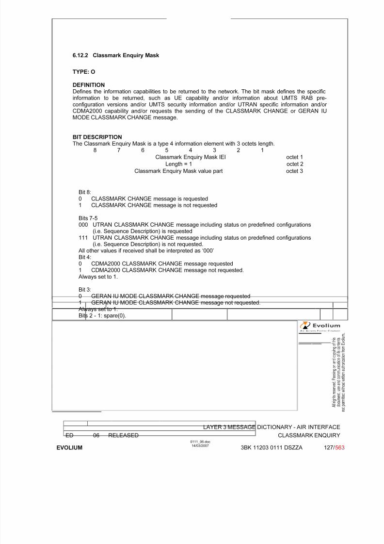
7/11/2019 1. Layer3 Air Interface Messages 0111_06
http://slidepdf.com/reader/full/1-layer3-air-interface-messages-011106 127/562
LAYER 3 MESSAGE DICTIONARY - AIR INTERFACE
ED 06 RELEASED CLASSMARK ENQUIRY
EVOLIUM
0111_06.doc14/03/2007
3BK 11203 0111 DSZZA 127/ 563
6.12.2 Classmark Enquiry Mask
TYPE: O
DEFINITION Defines the information capabilities to be returned to the network. The bit mask defines the specificinformation to be returned, such as UE capability and/or information about UMTS RAB pre-configuration versions and/or UMTS security information and/or UTRAN specific information and/or CDMA2000 capability and/or requests the sending of the CLASSMARK CHANGE or GERAN IUMODE CLASSMARK CHANGE message.
BIT DESCRIPTION The Classmark Enquiry Mask is a type 4 information element with 3 octets length.
8 7 6 5 4 3 2 1
Classmark Enquiry Mask IEI octet 1
Length = 1 octet 2
Classmark Enquiry Mask value part octet 3
Bit 8:0 CLASSMARK CHANGE message is requested1 CLASSMARK CHANGE message is not requested
Bits 7-5000 UTRAN CLASSMARK CHANGE message including status on predefined configurations
(i.e. Sequence Description) is requested111 UTRAN CLASSMARK CHANGE message including status on predefined configurations
(i.e. Sequence Description) is not requested.
All other values if received shall be interpreted as ‘000’Bit 4:0 CDMA2000 CLASSMARK CHANGE message requested1 CDMA2000 CLASSMARK CHANGE message not requested.Always set to 1.
Bit 3:0 GERAN IU MODE CLASSMARK CHANGE message requested1 GERAN IU MODE CLASSMARK CHANGE message not requested.Always set to 1.Bits 2 - 1: spare(0).

7/11/2019 1. Layer3 Air Interface Messages 0111_06
http://slidepdf.com/reader/full/1-layer3-air-interface-messages-011106 128/562
LAYER 3 MESSAGE DICTIONARY - AIR INTERFACE
ED 06 RELEASED CM RE-ESTABLISHMENT REQUEST
EVOLIUM
0111_06.doc14/03/2007
3BK 11203 0111 DSZZA 128/ 563
6.13 CM RE-ESTABLISHMENT REQUEST
NAME CM RE-ESTABLISHMENT REQUEST
INTERFACE RADIO ABIS A
CHANNEL/ USAGE
SDCCH/FACCH BTS Transparent
3GPP-REF 24.008 NA
FUNCTION The BSC is only non transparent to the classmark information.
DIRECTION From: MS To: BSC
INFORMATION ELEMENT NAME TYPE COMMENT LENGTH(byte)
INFORMATIONELEMENT
LISTHeader Ciphering key sequence number spareMobile Station Classmark 2Mobile IdentityLocation Area Identification
M V M V M LV M LV C TV (1)
2½½4
2-96
IMPLEMENTATION MAXIMUM LENGTH 22
NORMAL SITUATION ABNORMAL SITUATION TIMER
FOLLOWINGEVENT T3101
SPECIFDOC. REF.
Radio Link Establishment (ref. [2])
T3101 is stopped on reception of this message.½ means one half octet.
(1) IE is present if TMSI is used as MS identity.
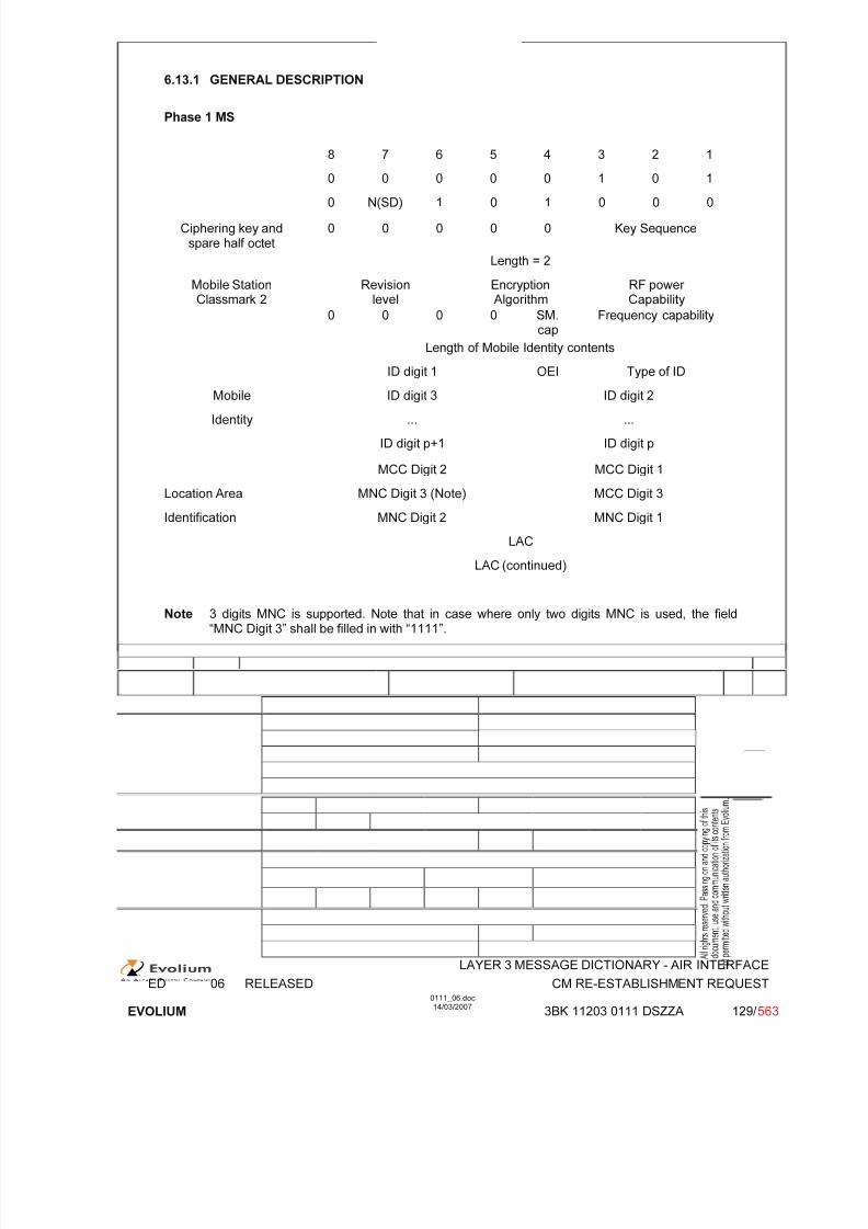
7/11/2019 1. Layer3 Air Interface Messages 0111_06
http://slidepdf.com/reader/full/1-layer3-air-interface-messages-011106 129/562
LAYER 3 MESSAGE DICTIONARY - AIR INTERFACE
ED 06 RELEASED CM RE-ESTABLISHMENT REQUEST
EVOLIUM
0111_06.doc14/03/2007
3BK 11203 0111 DSZZA 129/ 563
6.13.1 GENERAL DESCRIPTION
Phase 1 MS
8 7 6 5 4 3 2 1
0 0 0 0 0 1 0 1
0 N(SD) 1 0 1 0 0 0
Ciphering key andspare half octet
0 0 0 0 0 Key Sequence
Length = 2
Mobile StationClassmark 2
Revisionlevel
EncryptionAlgorithm
RF power Capability
0 0 0 0 SM.cap
Frequency capability
Length of Mobile Identity contents
ID digit 1 OEI Type of IDMobile ID digit 3 ID digit 2
Identity ... ...
ID digit p+1 ID digit p
MCC Digit 2 MCC Digit 1
Location Area MNC Digit 3 (Note) MCC Digit 3
Identification MNC Digit 2 MNC Digit 1
LAC
LAC (continued)
Note 3 digits MNC is supported. Note that in case where only two digits MNC is used, the field“MNC Digit 3” shall be filled in with “1111”.
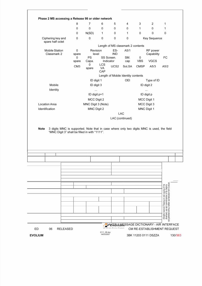
7/11/2019 1. Layer3 Air Interface Messages 0111_06
http://slidepdf.com/reader/full/1-layer3-air-interface-messages-011106 130/562
LAYER 3 MESSAGE DICTIONARY - AIR INTERFACE
ED 06 RELEASED CM RE-ESTABLISHMENT REQUEST
EVOLIUM
0111_06.doc14/03/2007
3BK 11203 0111 DSZZA 130/ 563
Phase 2 MS accessing a Release 98 or older network
8 7 6 5 4 3 2 1
0 0 0 0 0 1 0 1
0 N(SD) 1 0 1 0 0 0
Ciphering key andspare half octet
0 0 0 0 0 Key Sequence
Length of MS classmark 2 contents
Mobile StationClassmark 2
0spare
Revisionlevel
ES-IND
A5/1 RF power Capability
0spare
PSCapa.
SS Screen.Indicator
SM.cap
0VBS VGCS
FC
CM30
spare
LCSVA
CAP
UCS2 SoLSA CMSP A5/3 A5/2
Length of Mobile Identity contents
ID digit 1 OEI Type of ID
Mobile ID digit 3 ID digit 2
Identity ... ...
ID digit p+1 ID digit p
MCC Digit 2 MCC Digit 1
Location Area MNC Digit 3 (Note) MCC Digit 3
Identification MNC Digit 2 MNC Digit 1
LAC
LAC (continued)
Note 3 digits MNC is supported. Note that in case where only two digits MNC is used, the field
“MNC Digit 3” shall be filled in with “1111”.

7/11/2019 1. Layer3 Air Interface Messages 0111_06
http://slidepdf.com/reader/full/1-layer3-air-interface-messages-011106 131/562
LAYER 3 MESSAGE DICTIONARY - AIR INTERFACE
ED 06 RELEASED CM RE-ESTABLISHMENT REQUEST
EVOLIUM
0111_06.doc14/03/2007
3BK 11203 0111 DSZZA 131/ 563
Phase 2 MS accessing a Release 99 or newer network
8 7 6 5 4 3 2 1
0 0 0 0 0 1 0 1
N(SD) or 0 1 0 1 0 0 0
Ciphering key andspare half octet
0 0 0 0 0 Key Sequence
Length of MS classmark 2 contents
Mobile StationClassmark 2
0spare
Revisionlevel
ES-IND
A5/1 RF power Capability
0spare
PSCapa.
SS Screen.Indicator
SM.cap
0VBS VGCS
FC
CM30
spare
LCSVA
CAP
UCS2 SoLSA CMSP A5/3 A5/2
Length of Mobile Identity contents
ID digit 1 OEI Type of ID
Mobile ID digit 3 ID digit 2
Identity ... ...
ID digit p+1 ID digit p
MCC Digit 2 MCC Digit 1
Location Area MNC Digit 3 (Note) MCC Digit 3
Identification MNC Digit 2 MNC Digit 1
LAC
LAC (continued)
Note 3 digits MNC is supported. Note that in case where only two digits MNC is used, the field“MNC Digit 3” shall be filled in with “1111”.
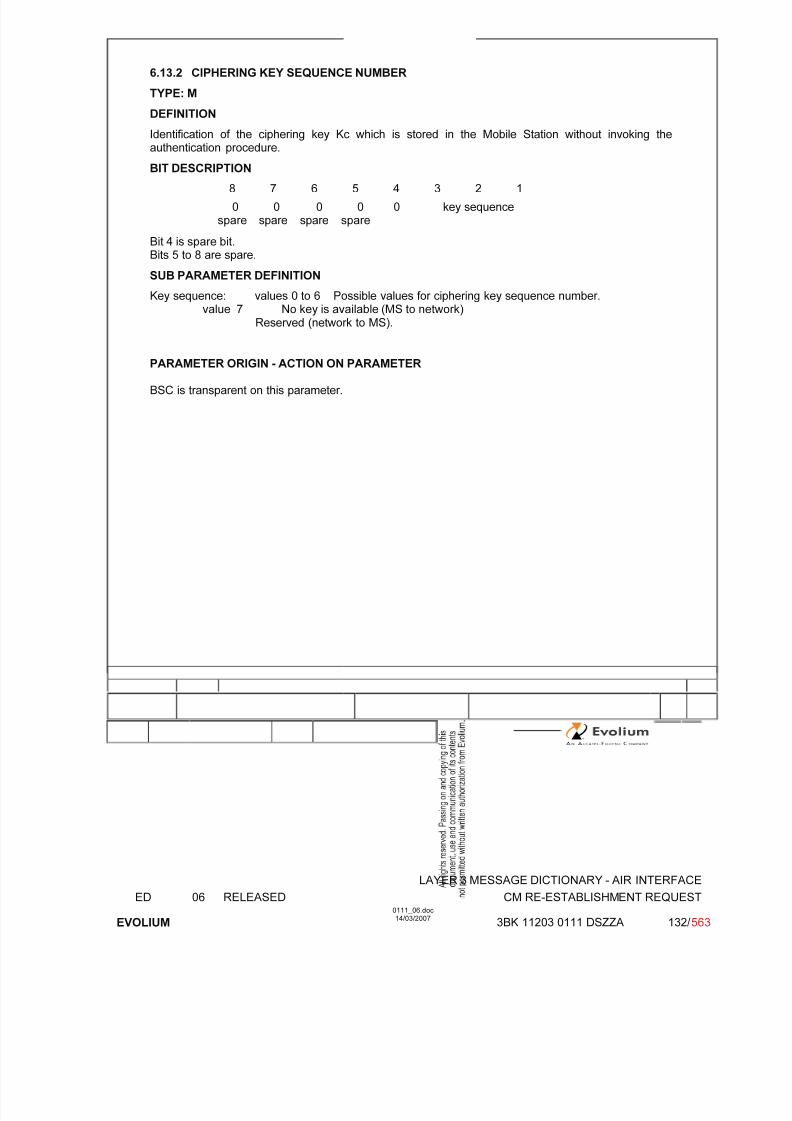
7/11/2019 1. Layer3 Air Interface Messages 0111_06
http://slidepdf.com/reader/full/1-layer3-air-interface-messages-011106 132/562
LAYER 3 MESSAGE DICTIONARY - AIR INTERFACE
ED 06 RELEASED CM RE-ESTABLISHMENT REQUEST
EVOLIUM
0111_06.doc14/03/2007
3BK 11203 0111 DSZZA 132/ 563
6.13.2 CIPHERING KEY SEQUENCE NUMBER
TYPE: M
DEFINITION
Identification of the ciphering key Kc which is stored in the Mobile Station without invoking theauthentication procedure.
BIT DESCRIPTION8 7 6 5 4 3 2 1
0spare
0spare
0spare
0spare
0 key sequence
Bit 4 is spare bit.Bits 5 to 8 are spare.
SUB PARAMETER DEFINITION
Key sequence: values 0 to 6 Possible values for ciphering key sequence number.value 7 No key is available (MS to network)
Reserved (network to MS).
PARAMETER ORIGIN - ACTION ON PARAMETER
BSC is transparent on this parameter.

7/11/2019 1. Layer3 Air Interface Messages 0111_06
http://slidepdf.com/reader/full/1-layer3-air-interface-messages-011106 133/562
LAYER 3 MESSAGE DICTIONARY - AIR INTERFACE
ED 06 RELEASED CM RE-ESTABLISHMENT REQUEST
EVOLIUM
0111_06.doc14/03/2007
3BK 11203 0111 DSZZA 133/ 563
6.13.3 MS CLASSMARK 2 - GSM Phase 1
TYPE: M
DEFINITION
Defines certain attributes of the Mobile Station equipment in use on a particular transaction.
BIT DESCRIPTION
8 7 6 5 4 3 2 1
Length 1
Revisionlevel
EncryptionAlgorithm
RF power Capability
2
0 0 0 0 SM.cap
Frequency capability 3
Bits 8-5 of octet 3 spare set to 0.
SUB PARAMETER DEFINITION
Octet 2Bits 8 7 6 Revision level 0 0 0 Reserved for phase 1.
All other values reserved Bits 5 4 Encryption Algorithm 0 0 algorithm A5/1
All other values reserved.Bits 3 2 1RF Power capability
GSM900 0 0 0 class 10 0 1 class 20 1 0 class 30 1 1 class 41 0 0 class 5
All other values reservedDCS1800 0 0 0 class 1
0 0 1 class 2All other values reserved
DCS1900 0 0 0 class 10 0 1 class 20 1 0 class 3
All other values reserved
Octet 3Bit 4SM Capability 0 short message capability not present
1 short message capability presentBits 3 2 1FC Frequency Capability 0 0 0 Band no 0
Other values reserved.
PARAMETER ORIGIN - ACTION ON PARAMETER
This is the MS classmark 2 as sent by a phase 1 MS.The BSC takes this information in order to have the MS power capability for the power controlalgorithm.Note: The BSC will decode the two octets of this IE value as if they were the two first octets of a
phase 2 MS classmark 2 IE value.

7/11/2019 1. Layer3 Air Interface Messages 0111_06
http://slidepdf.com/reader/full/1-layer3-air-interface-messages-011106 134/562
LAYER 3 MESSAGE DICTIONARY - AIR INTERFACE
ED 06 RELEASED CM RE-ESTABLISHMENT REQUEST
EVOLIUM
0111_06.doc14/03/2007
3BK 11203 0111 DSZZA 134/ 563
6.13.4 MS CLASSMARK 2 - GSM Phase 2
TYPE: M
DEFINITION Defines certain attributes of the Mobile Station equipment in use on a particular transaction.
BIT DESCRIPTION
8 7 6 5 4 3 2 1
Length 1
0spare
Revisionlevel
ESIND
A5/1 RF power Capability
2
0spare
PSCapa.
SS Screen.Indicator
SM.cap
VBS VGCS FC 3
CM30
spareLCSVA
CAP
UCS2 SoLSA CMSP A5/3 A5/24
Bit 8 of octet 2 spare set to 0,Bits 8 of octet 3 spare set to 0,
SUB PARAMETER DEFINITION
Octet 2:Bits 7 6Revision level 0 0 Reserved for phase 1
0 1 Used by phase 2 MS 1 0 Used by mobile stations supporting R99 or later
versions of the protocol All other value reserved
Bit 5ES-IND 0 Controlled Early Classmark Sending option not
implemented.1 Controlled Early Classmark Sending option
implemented.Bit 4A5/1 0 algorithm A5/1 available
1 algorithm A5/1 not available.Bits 3 2 1RF Power capability
P-GSM, GSM850 andE-GSM
0 0 0 class 1
0 0 1 class 2
0 1 0 class 30 1 1 class 41 0 0 class 5
All other values reservedDCS1800 0 0 0 class 1
0 0 1 class 20 1 0 class 3, handled as class 1
All other values reservedDCS1900 0 0 0 class 1
0 0 1 class 20 1 0 class 3, handled as class 1
All other values reserved

7/11/2019 1. Layer3 Air Interface Messages 0111_06
http://slidepdf.com/reader/full/1-layer3-air-interface-messages-011106 135/562
LAYER 3 MESSAGE DICTIONARY - AIR INTERFACE
ED 06 RELEASED CM RE-ESTABLISHMENT REQUEST
EVOLIUM
0111_06.doc14/03/2007
3BK 11203 0111 DSZZA 135/ 563
Octet 3:Bit 7PS Capability 0 PS capability not present
1 PS capability present
Bits 6 5
SS Screening Indicator 0 0 Defined in GSM 04.800 1 Defined in GSM 04.801 0 Defined in GSM 04.801 1 Defined in GSM 04.80
Bit 4SM Capability 0 MS does not support mobile terminated point to point
SMS.1 MS supports mobile terminated point to point SMS.
Bit 3VBS Voice BroadcastService
0 no VBS capability or no notifications wanted
1 VBS capability and notifications wantedNot implemented in the BSS.
Bit 2VGCS Voice GroupCall Service
0 no VGCS capability or no notifications wanted
1 VGCS capability and notifications wanted
Bit 1FC FrequencyCapability
GSM900 0 The MS does not support the extension band G1 inaddition to the primary GSM band.
1 The MS does support the extension band G1.GSM850, DCS1800,
DCS19000 Reserved for future use
Note: only FC is checked in this release and only in GSM900 configuration.

7/11/2019 1. Layer3 Air Interface Messages 0111_06
http://slidepdf.com/reader/full/1-layer3-air-interface-messages-011106 136/562
LAYER 3 MESSAGE DICTIONARY - AIR INTERFACE
ED 06 RELEASED CM RE-ESTABLISHMENT REQUEST
EVOLIUM
0111_06.doc14/03/2007
3BK 11203 0111 DSZZA 136/ 563
Octet 4Bit 8CM3 Classmark 3 0 No additional MS capability
1 Additional MS capabilities are described in the MSClassmark 3 information element.
Bit 6LCS VA capability 0 LCS value added location request notification capability not
supported1 LCS value added location request notification capabilitysupported
Not implemented in the BSS.Bit 5UCS2 treatment 0 the ME has a preference for the default alphabet (defined in
GSM 03.38) over UCS21 the ME has no preference between the use of the default
alphabet and the use of UCS2.Not implemented in the BSS.
Bit 4SoLSA 0 The ME does not support SoLSA
1 The ME supports SoLSA.
Bit 3CMSP: CM Service Prompt 0 "Network initiated MO CM connection request" not supported1 "Network initiated MO CM connection request" supported for
at least one CM protocol.Not implemented in the BSS.
Bit 2A5/3 algorithm supported 0 A5/3 not available
1 A5/3 available
Bit 1A5/2 algorithm supported 0 A5/2 not available
1 A5/2 availableNote: only A5/2 is checked in this release.
PARAMETER ORIGIN - ACTION ON PARAMETER
The BSC takes this information in order to have the MS power capability for the power controlalgorithm, the MS frequency capability and the MS ciphering capability.Additional mobile info can be obtained by invoking the classmark interrogation procedure.
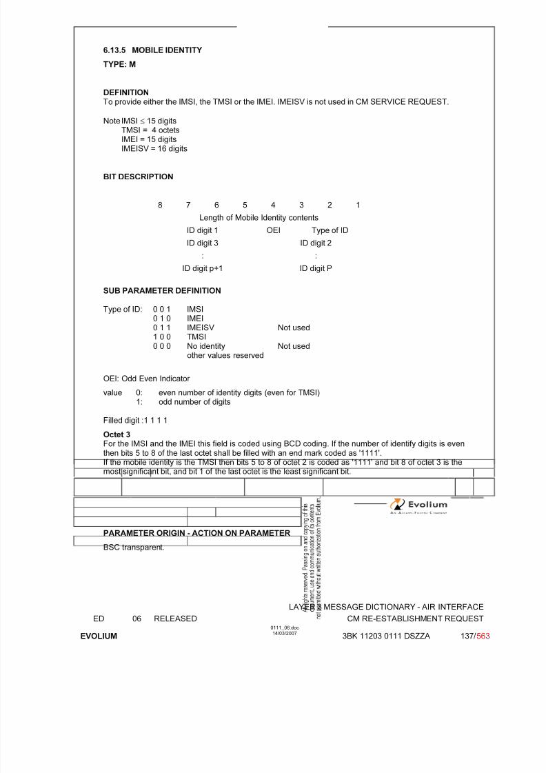
7/11/2019 1. Layer3 Air Interface Messages 0111_06
http://slidepdf.com/reader/full/1-layer3-air-interface-messages-011106 137/562
LAYER 3 MESSAGE DICTIONARY - AIR INTERFACE
ED 06 RELEASED CM RE-ESTABLISHMENT REQUEST
EVOLIUM
0111_06.doc14/03/2007
3BK 11203 0111 DSZZA 137/ 563
6.13.5 MOBILE IDENTITY
TYPE: M
DEFINITIONTo provide either the IMSI, the TMSI or the IMEI. IMEISV is not used in CM SERVICE REQUEST.
Note IMSI ≤ 15 digitsTMSI = 4 octetsIMEI = 15 digitsIMEISV = 16 digits
BIT DESCRIPTION
8 7 6 5 4 3 2 1
Length of Mobile Identity contents
ID digit 1 OEI Type of ID
ID digit 3 ID digit 2
: :
ID digit p+1 ID digit P
SUB PARAMETER DEFINITION
Type of ID: 0 0 1 IMSI0 1 0 IMEI0 1 1 IMEISV Not used1 0 0 TMSI0 0 0 No identity Not used
other values reserved
OEI: Odd Even Indicator
value 0: even number of identity digits (even for TMSI)1: odd number of digits
Filled digit :1 1 1 1
Octet 3 For the IMSI and the IMEI this field is coded using BCD coding. If the number of identify digits is eventhen bits 5 to 8 of the last octet shall be filled with an end mark coded as '1111'.If the mobile identity is the TMSI then bits 5 to 8 of octet 2 is coded as '1111' and bit 8 of octet 3 is themost significant bit, and bit 1 of the last octet is the least significant bit.
PARAMETER ORIGIN - ACTION ON PARAMETER
BSC transparent.
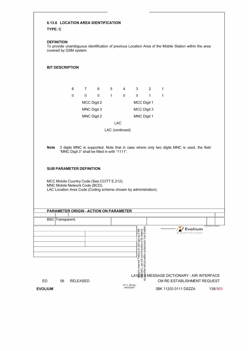
7/11/2019 1. Layer3 Air Interface Messages 0111_06
http://slidepdf.com/reader/full/1-layer3-air-interface-messages-011106 138/562
LAYER 3 MESSAGE DICTIONARY - AIR INTERFACE
ED 06 RELEASED CM RE-ESTABLISHMENT REQUEST
EVOLIUM
0111_06.doc14/03/2007
3BK 11203 0111 DSZZA 138/ 563
6.13.6 LOCATION AREA IDENTIFICATION
TYPE: C
DEFINITIONTo provide unambiguous identification of previous Location Area of the Mobile Station within the areacovered by GSM system.
BIT DESCRIPTION
8 7 6 5 4 3 2 1
0 0 0 1 0 0 1 1
MCC Digit 2 MCC Digit 1
MNC Digit 3 MCC Digit 3
MNC Digit 2 MNC Digit 1
LAC
LAC (continued)
Note 3 digits MNC is supported. Note that in case where only two digits MNC is used, the field“MNC Digit 3” shall be filled in with “1111”.
SUB PARAMETER DEFINITION
MCC Mobile Country Code (See CCITT E.212).MNC Mobile Network Code (BCD).LAC Location Area Code (Coding scheme chosen by administration).
PARAMETER ORIGIN - ACTION ON PARAMETER
BSC Transparent.
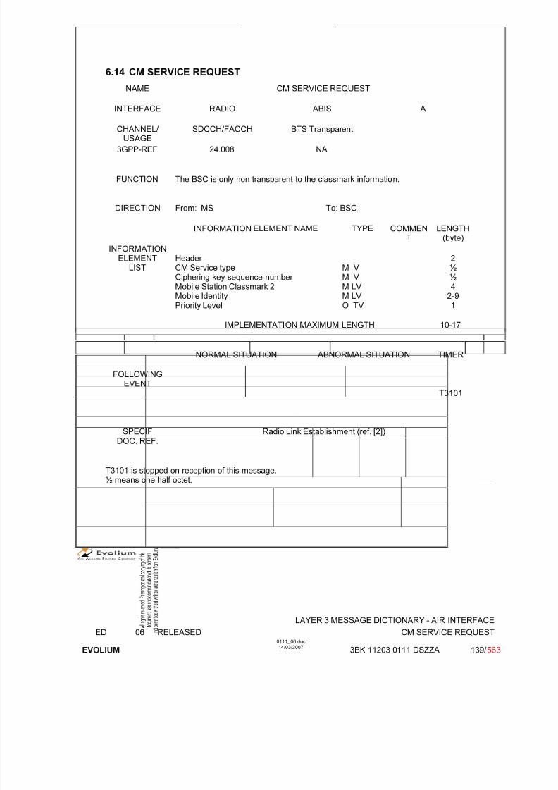
7/11/2019 1. Layer3 Air Interface Messages 0111_06
http://slidepdf.com/reader/full/1-layer3-air-interface-messages-011106 139/562
LAYER 3 MESSAGE DICTIONARY - AIR INTERFACE
ED 06 RELEASED CM SERVICE REQUEST
EVOLIUM
0111_06.doc14/03/2007
3BK 11203 0111 DSZZA 139/ 563
6.14 CM SERVICE REQUEST
NAME CM SERVICE REQUEST
INTERFACE RADIO ABIS A
CHANNEL/ USAGE
SDCCH/FACCH BTS Transparent
3GPP-REF 24.008 NA
FUNCTION The BSC is only non transparent to the classmark information.
DIRECTION From: MS To: BSC
INFORMATION ELEMENT NAME TYPE COMMENT
LENGTH(byte)
INFORMATIONELEMENT
LISTHeader CM Service typeCiphering key sequence number Mobile Station Classmark 2Mobile IdentityPriority Level
M V M V M LV M LV O TV
2½½4
2-91
IMPLEMENTATION MAXIMUM LENGTH 10-17
NORMAL SITUATION ABNORMAL SITUATION TIMER
FOLLOWINGEVENT
T3101
SPECIFDOC. REF.
Radio Link Establishment (ref. [2])
T3101 is stopped on reception of this message.½ means one half octet.

7/11/2019 1. Layer3 Air Interface Messages 0111_06
http://slidepdf.com/reader/full/1-layer3-air-interface-messages-011106 140/562
LAYER 3 MESSAGE DICTIONARY - AIR INTERFACE
ED 06 RELEASED CM SERVICE REQUEST
EVOLIUM
0111_06.doc14/03/2007
3BK 11203 0111 DSZZA 140/ 563
6.14.1 GENERAL DESCRIPTION
Phase 1 MS
8 7 6 5 4 3 2 1
0 0 0 0 0 1 0 1
0 N(SD) 1 0 0 1 0 0
Ciphering key andCM service type
0 Key Sequence Service Type
Length = 2
Mobile StationClassmark 2
Revisionlevel
EncryptionAlgorithm
RF power Capability
0 0 0 0 SM.cap
Frequency capability
Length of Mobile Identity contents
ID digit 1 OEI Type of ID
Mobile ID digit 3 ID digit 2
Identity ... ...
ID digit p+1 ID digit p
Phase 2 MS
8 7 6 5 4 3 2 10 0 0 0 0 1 0 1
0 N(SD) 1 0 0 1 0 0
Ciphering key andCM service type
0 Key Sequence Service Type
Length of MS classmark 2 contents
Mobile StationClassmark 2
0spare
Revisionlevel
ES-IND
A5/1 RF power Capability
0spare
PSCapa.
SS Screen.Indicator
SM.cap
0VBS VGCS
FC
CM3 0spare
LCSVA
CAP
UCS2 SoLSA CMSP A5/3 A5/2
Length of Mobile Identity contents
ID digit 1 OEI Type of ID
Mobile ID digit 3 ID digit 2
Identity ... ...
ID digit p+1 ID digit p

7/11/2019 1. Layer3 Air Interface Messages 0111_06
http://slidepdf.com/reader/full/1-layer3-air-interface-messages-011106 141/562
LAYER 3 MESSAGE DICTIONARY - AIR INTERFACE
ED 06 RELEASED CM SERVICE REQUEST
EVOLIUM
0111_06.doc14/03/2007
3BK 11203 0111 DSZZA 141/ 563
Phase 2+ MS accessing a Release 98 or older network
8 7 6 5 4 3 2 1
0 0 0 0 0 1 0 1
0 N(SD) 1 0 0 1 0 0
Ciphering key andCM service type
0 Key Sequence Service Type
Length of MS classmark 2 contents
Mobile StationClassmark 2
0spare
Revisionlevel
ES-IND
A5/1 RF power Capability
0spare
PSCapa.
SS Screen.Indicator
SM.cap
0VBS VGCS
FC
CM3 0spare
LCSVA
CAP
UCS2 SoLSA CMSP A5/3 A5/2
Length of Mobile Identity contents
ID digit 1 OEI Type of ID
Mobile ID digit 3 ID digit 2
Identity ... ...
ID digit p+1 ID digit p
Priority Level 1 0 0 0 0 call priority
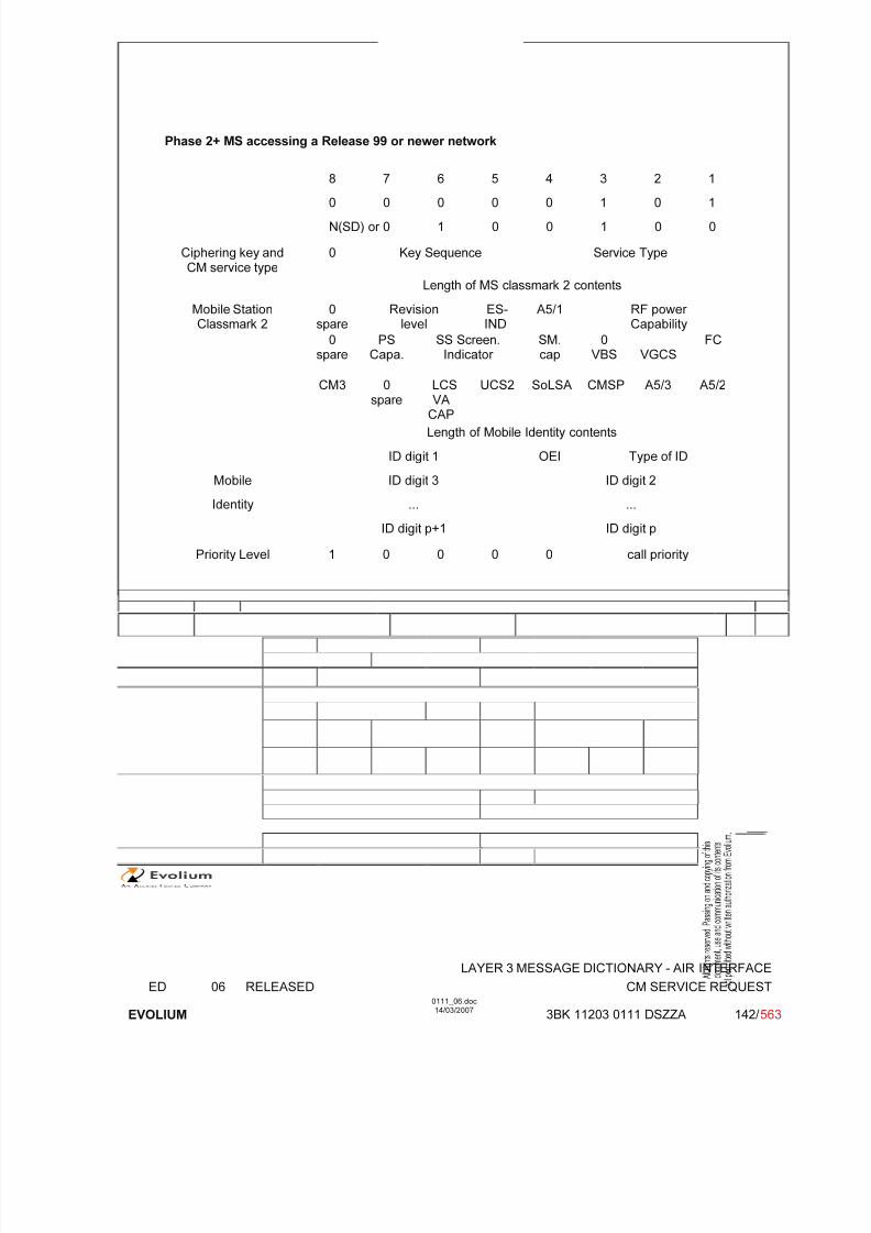
7/11/2019 1. Layer3 Air Interface Messages 0111_06
http://slidepdf.com/reader/full/1-layer3-air-interface-messages-011106 142/562
LAYER 3 MESSAGE DICTIONARY - AIR INTERFACE
ED 06 RELEASED CM SERVICE REQUEST
EVOLIUM
0111_06.doc14/03/2007
3BK 11203 0111 DSZZA 142/ 563
Phase 2+ MS accessing a Release 99 or newer network
8 7 6 5 4 3 2 1
0 0 0 0 0 1 0 1
N(SD) or 0 1 0 0 1 0 0
Ciphering key andCM service type
0 Key Sequence Service Type
Length of MS classmark 2 contents
Mobile StationClassmark 2
0spare
Revisionlevel
ES-IND
A5/1 RF power Capability
0spare
PSCapa.
SS Screen.Indicator
SM.cap
0VBS VGCS
FC
CM3 0spare
LCSVA
CAP
UCS2 SoLSA CMSP A5/3 A5/2
Length of Mobile Identity contents
ID digit 1 OEI Type of ID
Mobile ID digit 3 ID digit 2
Identity ... ...
ID digit p+1 ID digit p
Priority Level 1 0 0 0 0 call priority

7/11/2019 1. Layer3 Air Interface Messages 0111_06
http://slidepdf.com/reader/full/1-layer3-air-interface-messages-011106 143/562
LAYER 3 MESSAGE DICTIONARY - AIR INTERFACE
ED 06 RELEASED CM SERVICE REQUEST
EVOLIUM
0111_06.doc14/03/2007
3BK 11203 0111 DSZZA 143/ 563
6.14.2 CM SERVICE TYPE
TYPE: M
DEFINITIONTo specify which service is requested from the network.
BIT DESCRIPTION
8 7 6 5 4 3 2 1
Service type
SUB PARAMETER DEFINITION
Phase 1:
0 0 0 1: Mobile originated call establishment or packet mode connection establishment0 0 1 0: Emergency call establishment0 1 0 0: Short message service1 0 0 0: Supplementary service activation
other values are reserved.
Phase 2:0 0 0 1: Mobile originated call establishment or packet mode
connection establishment0 0 1 0: Emergency call establishment0 1 0 0: Short message service1 0 0 0: Supplementary service activation
1 0 0 1: Voice group call establishment1 0 1 0: Voice broadcast call establishment not implemented1 0 1 1: Location Services
PARAMETER ORIGIN - ACTION ON PARAMETER
This parameter is transparent to the BSC and the BTS.
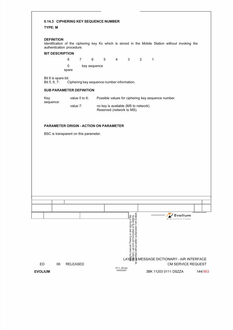
7/11/2019 1. Layer3 Air Interface Messages 0111_06
http://slidepdf.com/reader/full/1-layer3-air-interface-messages-011106 144/562
LAYER 3 MESSAGE DICTIONARY - AIR INTERFACE
ED 06 RELEASED CM SERVICE REQUEST
EVOLIUM
0111_06.doc14/03/2007
3BK 11203 0111 DSZZA 144/ 563
6.14.3 CIPHERING KEY SEQUENCE NUMBER
TYPE: M
DEFINITIONIdentification of the ciphering key Kc which is stored in the Mobile Station without invoking theauthentication procedure.
BIT DESCRIPTION
8 7 6 5 4 3 2 1
0spare
key sequence
Bit 8 is spare bit.Bit 5, 6, 7: Ciphering key sequence number information.
SUB PARAMETER DEFINITION
Key
sequence:
value 0 to 6: Possible values for ciphering key sequence number.
value 7: no key is available (MS to network)Reserved (network to MS).
PARAMETER ORIGIN - ACTION ON PARAMETER
BSC is transparent on this parameter.

7/11/2019 1. Layer3 Air Interface Messages 0111_06
http://slidepdf.com/reader/full/1-layer3-air-interface-messages-011106 145/562
LAYER 3 MESSAGE DICTIONARY - AIR INTERFACE
ED 06 RELEASED CM SERVICE REQUEST
EVOLIUM
0111_06.doc14/03/2007
3BK 11203 0111 DSZZA 145/ 563
6.14.4 MS CLASSMARK 2 - GSM Phase 1
TYPE: M
DEFINITION Defines certain attributes of the Mobile Station equipment in use on a particular transaction.
BIT DESCRIPTION
8 7 6 5 4 3 2 1
Length 1
Revisionlevel
EncryptionAlgorithm
RF power Capability
2
0 0 0 0 SM.cap
Frequency capability 3
Bits 8-5 of octet 3 spare set to 0
SUB PARAMETER DEFINITION
Octet 2Bits 8 7 6 Revision level 0 0 0 Reserved for phase 1.
All other values reserved Bits 5 4 Encryption Algorithm 0 0 algorithm A5/1
All other values reserved.Bits 3 2 1RF Power capability
GSM900 0 0 0 class 10 0 1 class 20 1 0 class 3
0 1 1 class 41 0 0 class 5
All other values reservedDCS1800 0 0 0 class 1
0 0 1 class 2All other values reserved
DCS1900 0 0 0 class 10 0 1 class 20 1 0 class 3
All other values reserved
Octet 3Bit 4
SM Capability 0 short message capability not present1 short message capability present
Bits 3 2 1FC Frequency Capability 0 0 0 Band no 0
Other values reserved.

7/11/2019 1. Layer3 Air Interface Messages 0111_06
http://slidepdf.com/reader/full/1-layer3-air-interface-messages-011106 146/562
LAYER 3 MESSAGE DICTIONARY - AIR INTERFACE
ED 06 RELEASED CM SERVICE REQUEST
EVOLIUM
0111_06.doc14/03/2007
3BK 11203 0111 DSZZA 146/ 563
PARAMETER ORIGIN - ACTION ON PARAMETER
This is the MS classmark 2 as sent by a phase 1 MS.
The BSC takes this information in order to have the MS power capability for the power controlalgorithm.
Note: The BSC will decode the two octets of this IE value as if they were the two first octets of a
phase 2 MS classmark 2 IE value.
6.14.5 MS CLASSMARK 2 - GSM Phase 2
TYPE: M
DEFINITION Defines certain attributes of the Mobile Station equipment in use on a particular transaction.
BIT DESCRIPTION
8 7 6 5 4 3 2 1
Length 1
0spare
Revisionlevel
ESIND
A5/1 RF power Capability
2
0spare
PSCapa.
SS Screen.Indicator
SM.cap VBS VGCS
FC 3
CM30
spareLCSVA
CAP
UCS2 SoLSA CMSP A5/3 A5/24
Bit 8 of octet 2 spare set to 0Bits 8 of octet 3 spare set to 0
SUB PARAMETER DEFINITION
Octet 2:Bits 7 6Revision level 0 0 Reserved for phase 1
0 1 Used by phase 2 MS 1 0 Used by mobile stations supporting R99 or later
versions of the protocol All other value reserved
Bit 5ES-IND 0 Controlled Early Classmark Sending option not
implemented.1 Controlled Early Classmark Sending option
implemented.Bit 4A5/1 0 algorithm A5/1 available
1 algorithm A5/1 not available.Bits 3 2 1RF Power capability
P-GSM, GSM850 andE-GSM
0 0 0 class 1
0 0 1 class 2

7/11/2019 1. Layer3 Air Interface Messages 0111_06
http://slidepdf.com/reader/full/1-layer3-air-interface-messages-011106 147/562
LAYER 3 MESSAGE DICTIONARY - AIR INTERFACE
ED 06 RELEASED CM SERVICE REQUEST
EVOLIUM
0111_06.doc14/03/2007
3BK 11203 0111 DSZZA 147/ 563
0 1 0 class 30 1 1 class 41 0 0 class 5
All other values reservedDCS1800 0 0 0 class 1
0 0 1 class 20 1 0 class 3, handled as class 1
All other values reservedDCS1900 0 0 0 class 10 0 1 class 20 1 0 class 3, handled as class 1
All other values reserved
Octet 3:Bit 7PS Capability 0 PS capability not present
1 PS capability presentBits 6 5
SS Screening Indicator 0 0 Defined in GSM 04.800 1 Defined in GSM 04.801 0 Defined in GSM 04.801 1 Defined in GSM 04.80
Bit 4SM Capability 0 MS does not support mobile terminated point to point
SMS.1 MS supports mobile terminated point to point SMS.
Bit 3VBS Voice BroadcastService
0 no VBS capability or no notifications wanted
1 VBS capability and notifications wantedNot implemented in the BSS.
Bit 2VGCS Voice GroupCall Service
0 no VGCS capability or no notifications wanted
1 VGCS capability and notifications wanted
Bit 1FC FrequencyCapability
GSM900 0 The MS does not support the extension band G1 inaddition to the primary GSM band.
1 The MS does support the extension band G1.GSM850, DCS1800,
DCS19000 Reserved for future use
Note: only FC is checked in this release and only in GSM900 configuration.

7/11/2019 1. Layer3 Air Interface Messages 0111_06
http://slidepdf.com/reader/full/1-layer3-air-interface-messages-011106 148/562
LAYER 3 MESSAGE DICTIONARY - AIR INTERFACE
ED 06 RELEASED CM SERVICE REQUEST
EVOLIUM
0111_06.doc14/03/2007
3BK 11203 0111 DSZZA 148/ 563
Octet 4Bit 8CM3 Classmark 3 0 No additional MS capability
1 Additional MS capabilities are described in the MSClassmark 3 information element.
Bit 6LCS VA capability 0 LCS value added location request notification capability not
supported1 LCS value added location request notification capabilitysupported
Not implemented in the BSS.Bit 5UCS2 treatment 0 the ME has a preference for the default alphabet (defined in
GSM 03.38) over UCS21 the ME has no preference between the use of the default
alphabet and the use of UCS2.Not implemented in the BSS.
Bit 4SoLSA 0 The ME does not support SoLSA
1 The ME supports SoLSA.
Bit 3CMSP: CM Service Prompt 0 "Network initiated MO CM connection request" not supported1 "Network initiated MO CM connection request" supported for
at least one CM protocol.Not implemented in the BSS.
Bit 2A5/3 algorithm supported 0 A5/3 not available
1 A5/3 available
Bit 1A5/2 algorithm supported 0 A5/2 not available
1 A5/2 availableNote: only A5/2 is checked in this release.
PARAMETER ORIGIN - ACTION ON PARAMETER
The BSC takes this information in order to have the MS power capability for the power controlalgorithm, the MS frequency capability and the MS ciphering capability.Additional mobile info can be obtained by invoking the classmark interrogation procedure.
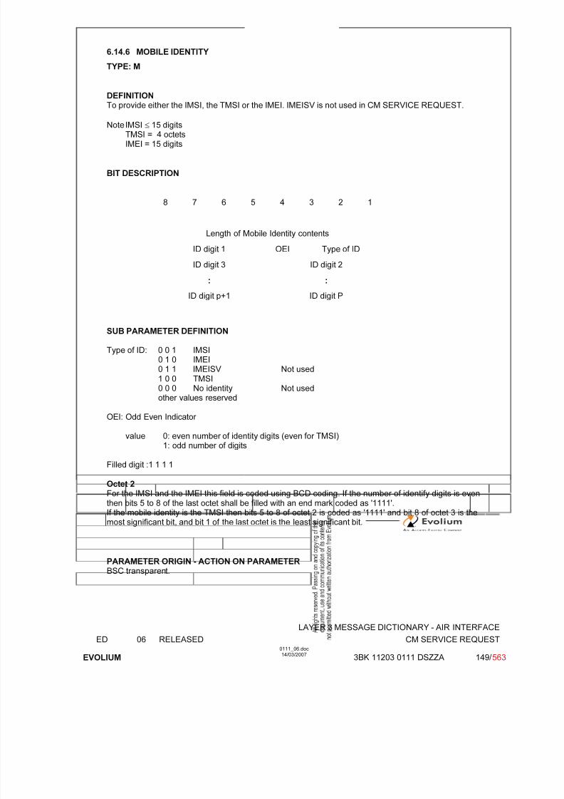
7/11/2019 1. Layer3 Air Interface Messages 0111_06
http://slidepdf.com/reader/full/1-layer3-air-interface-messages-011106 149/562
LAYER 3 MESSAGE DICTIONARY - AIR INTERFACE
ED 06 RELEASED CM SERVICE REQUEST
EVOLIUM
0111_06.doc14/03/2007
3BK 11203 0111 DSZZA 149/ 563
6.14.6 MOBILE IDENTITY
TYPE: M
DEFINITIONTo provide either the IMSI, the TMSI or the IMEI. IMEISV is not used in CM SERVICE REQUEST.
Note IMSI ≤ 15 digitsTMSI = 4 octetsIMEI = 15 digits
BIT DESCRIPTION
8 7 6 5 4 3 2 1
Length of Mobile Identity contents
ID digit 1 OEI Type of ID
ID digit 3 ID digit 2
: :
ID digit p+1 ID digit P
SUB PARAMETER DEFINITION
Type of ID: 0 0 1 IMSI0 1 0 IMEI
0 1 1 IMEISV Not used1 0 0 TMSI0 0 0 No identity Not usedother values reserved
OEI: Odd Even Indicator
value 0: even number of identity digits (even for TMSI)1: odd number of digits
Filled digit :1 1 1 1
Octet 2
For the IMSI and the IMEI this field is coded using BCD coding. If the number of identify digits is eventhen bits 5 to 8 of the last octet shall be filled with an end mark coded as '1111'.If the mobile identity is the TMSI then bits 5 to 8 of octet 2 is coded as '1111' and bit 8 of octet 3 is themost significant bit, and bit 1 of the last octet is the least significant bit.
PARAMETER ORIGIN - ACTION ON PARAMETERBSC transparent.
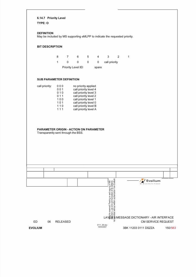
7/11/2019 1. Layer3 Air Interface Messages 0111_06
http://slidepdf.com/reader/full/1-layer3-air-interface-messages-011106 150/562
LAYER 3 MESSAGE DICTIONARY - AIR INTERFACE
ED 06 RELEASED CM SERVICE REQUEST
EVOLIUM
0111_06.doc14/03/2007
3BK 11203 0111 DSZZA 150/ 563
6.14.7 Priority Level
TYPE: O
DEFINITIONMay be included by MS supporting eMLPP to indicate the requested priority.
BIT DESCRIPTION
8 7 6 5 4 3 2 1
1 0 0 0 0 call priority
Priority Level IEI spare
SUB PARAMETER DEFINITION
call priority: 0 0 0 no priority applied0 0 1 call priority level 40 1 0 call priority level 30 1 1 call priority level 21 0 0 call priority level 11 0 1 call priority level 01 1 0 call priority level B1 1 1 call priority level A
PARAMETER ORIGIN - ACTION ON PARAMETERTransparently sent through the BSS.
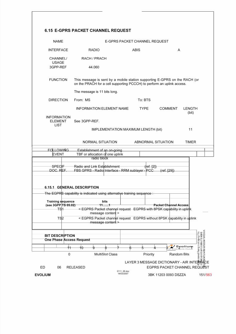
7/11/2019 1. Layer3 Air Interface Messages 0111_06
http://slidepdf.com/reader/full/1-layer3-air-interface-messages-011106 151/562
LAYER 3 MESSAGE DICTIONARY - AIR INTERFACE
ED 06 RELEASED EGPRS PACKET CHANNEL REQUEST
EVOLIUM
0111_06.doc14/03/2007
3BK 11203 0093 DSZZA 151/ 563
6.15 E-GPRS PACKET CHANNEL REQUEST
NAME E-GPRS PACKET CHANNEL REQUEST
INTERFACE RADIO ABIS A
CHANNEL/ USAGE
RACH / PRACH
3GPP-REF 44.060
FUNCTION This message is sent by a mobile station supporting E-GPRS on the RACH (or on the PRACH for a cell supporting PCCCH) to perform an uplink access.
The message is 11 bits long.
DIRECTION From: MS To: BTS
INFORMATION ELEMENT NAME TYPE COMMENT LENGTH(bit)
INFORMATIONELEMENT
LISTSee 3GPP-REF.
IMPLEMENTATION MAXIMUM LENGTH (bit) 11
NORMAL SITUATION ABNORMAL SITUATION TIMER
FOLLOWING
EVENT
Establishment of an on-going
TBF or allocation of one uplinkradio block
SPECIFDOC. REF.
Radio and Link Establishment (ref. [2])FBS GPRS - Radio Interface - RRM sublayer - PCC (ref. [29])
6.15.1 GENERAL DESCRIPTION
The EGPRS capability is indicated using alternative training sequence :
Training sequence
(see 3GPP TS 05.02)
bits
11…...1 Packet Channel AccessTS1 < EGPRS Packet channel request
message content >EGPRS with 8PSK capability in uplink
TS2 < EGPRS Packet channel requestmessage content >
EGPRS without 8PSK capability in uplink
BIT DESCRIPTIONOne Phase Access Request
11 10 9 8 7 6 5 4 3 2 1
0 MultiSlot Class Priority Random Bits

7/11/2019 1. Layer3 Air Interface Messages 0111_06
http://slidepdf.com/reader/full/1-layer3-air-interface-messages-011106 152/562
LAYER 3 MESSAGE DICTIONARY - AIR INTERFACE
ED 06 RELEASED EGPRS PACKET CHANNEL REQUEST
EVOLIUM
0111_06.doc14/03/2007
3BK 11203 0093 DSZZA 152/ 563
Short Access Request
11 10 9 8 7 6 5 4 3 2 1
1 0 0 Nb Of Blocks Priority Random Bits
Two-Phase Access Request
11 10 9 8 7 6 5 4 3 2 1
1 1 0 0 0 0 Priority Random Bits
Signalling
11 10 9 8 7 6 5 4 3 2 1
1 1 0 0 1 1 Random Bits
SUB PARAMETER DEFINITION
MultiSlot ClassThe Multi Slot Class field is coded as the binary representation of the multislot class defined in3GPP TS 05.02.
Bits5 4 3 2 10 0 0 0 0 MultiSlot Class 10 0 0 0 1 MultiSlot Class 2…1 1 1 0 0 MultiSlot Class 29
other Reserved values
PriorityThis information field indicates the requested Radio Priority.
Bits2 10 0 Radio Priority 1 (Highest priority)0 1 Radio Priority 21 0 Radio Priority 31 1 Radio Priority 4 (Lower priority)
Number Of Blocks
This information field indicates the number of blocks requested during a mobile originated TemporaryBlock Flow. This field is coded as shown in the following table:
Bits3 2 10 0 0 1 RLC data block0 0 1 2 RLC data blocks…1 1 1 8 RLC data blocks
Random bits
This is an unformatted field of variable length of 3 bits

7/11/2019 1. Layer3 Air Interface Messages 0111_06
http://slidepdf.com/reader/full/1-layer3-air-interface-messages-011106 153/562
LAYER 3 MESSAGE DICTIONARY - AIR INTERFACE
ED 06 RELEASED EGPRS PACKET CHANNEL REQUEST
EVOLIUM
0111_06.doc14/03/2007
3BK 11203 0093 DSZZA 153/ 563
PARAMETER ORIGIN - ACTION ON PARAMETER
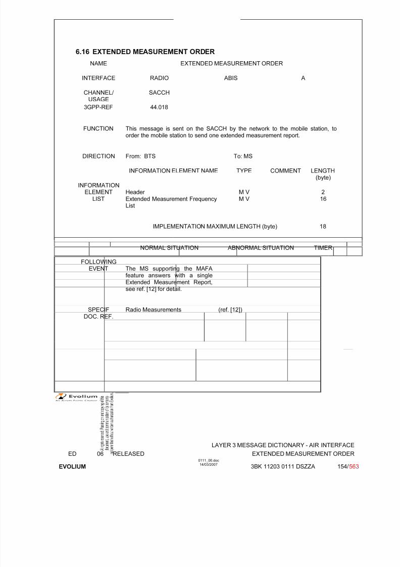
7/11/2019 1. Layer3 Air Interface Messages 0111_06
http://slidepdf.com/reader/full/1-layer3-air-interface-messages-011106 154/562
LAYER 3 MESSAGE DICTIONARY - AIR INTERFACE
ED 06 RELEASED EXTENDED MEASUREMENT ORDER
EVOLIUM
0111_06.doc14/03/2007
3BK 11203 0111 DSZZA 154/ 563
6.16 EXTENDED MEASUREMENT ORDER
NAME EXTENDED MEASUREMENT ORDER
INTERFACE RADIO ABIS A
CHANNEL/ USAGE
SACCH
3GPP-REF 44.018
FUNCTION This message is sent on the SACCH by the network to the mobile station, toorder the mobile station to send one extended measurement report.
DIRECTION From: BTS To: MS
INFORMATION ELEMENT NAME TYPE COMMENT LENGTH(byte)
INFORMATIONELEMENT
LISTHeader Extended Measurement FrequencyList
M V M V
216
IMPLEMENTATION MAXIMUM LENGTH (byte) 18
NORMAL SITUATION ABNORMAL SITUATION TIMER
FOLLOWINGEVENT The MS supporting the MAFA
feature answers with a singleExtended Measurement Report,see ref. [12] for detail.
SPECIFDOC. REF.
Radio Measurements (ref. [12])
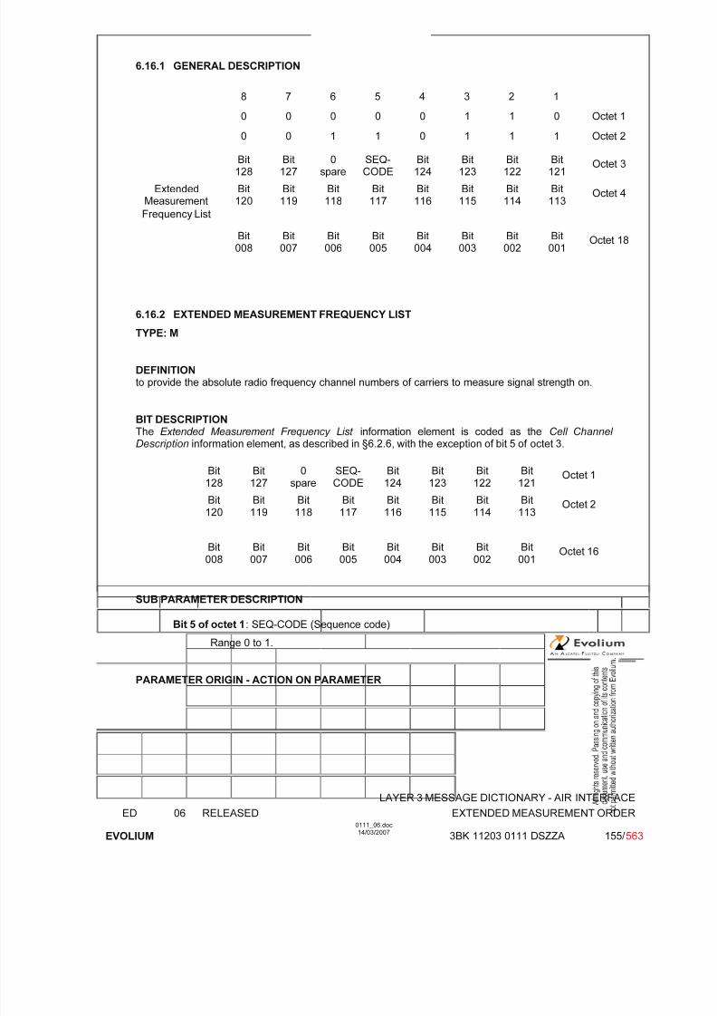
7/11/2019 1. Layer3 Air Interface Messages 0111_06
http://slidepdf.com/reader/full/1-layer3-air-interface-messages-011106 155/562
LAYER 3 MESSAGE DICTIONARY - AIR INTERFACE
ED 06 RELEASED EXTENDED MEASUREMENT ORDER
EVOLIUM
0111_06.doc14/03/2007
3BK 11203 0111 DSZZA 155/ 563
6.16.1 GENERAL DESCRIPTION
8 7 6 5 4 3 2 1
0 0 0 0 0 1 1 0 Octet 1
0 0 1 1 0 1 1 1 Octet 2
Bit128
Bit127
0spare
SEQ-CODE
Bit124
Bit123
Bit122
Bit121
Octet 3
ExtendedMeasurement
Bit120
Bit119
Bit118
Bit117
Bit116
Bit115
Bit114
Bit113
Octet 4
Frequency List
Bit008
Bit007
Bit006
Bit005
Bit004
Bit003
Bit002
Bit001
Octet 18
6.16.2 EXTENDED MEASUREMENT FREQUENCY LIST
TYPE: M
DEFINITIONto provide the absolute radio frequency channel numbers of carriers to measure signal strength on.
BIT DESCRIPTIONThe Extended Measurement Frequency List information element is coded as the Cell Channel Description information element, as described in §6.2.6, with the exception of bit 5 of octet 3.
Bit128
Bit127
0spare
SEQ-CODE
Bit124
Bit123
Bit122
Bit121
Octet 1
Bit120
Bit119
Bit118
Bit117
Bit116
Bit115
Bit114
Bit113
Octet 2
Bit008
Bit007
Bit006
Bit005
Bit004
Bit003
Bit002
Bit001
Octet 16
SUB PARAMETER DESCRIPTION
Bit 5 of octet 1: SEQ-CODE (Sequence code)
Range 0 to 1.
PARAMETER ORIGIN - ACTION ON PARAMETER
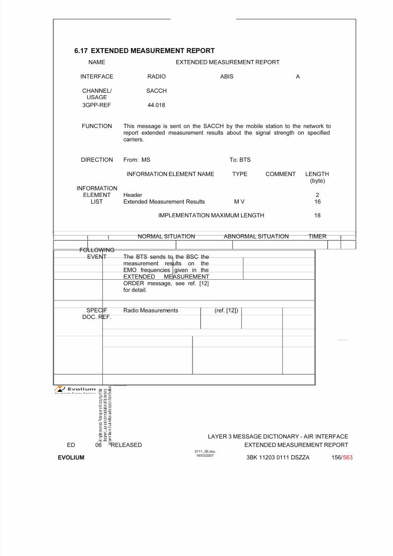
7/11/2019 1. Layer3 Air Interface Messages 0111_06
http://slidepdf.com/reader/full/1-layer3-air-interface-messages-011106 156/562
LAYER 3 MESSAGE DICTIONARY - AIR INTERFACE
ED 06 RELEASED EXTENDED MEASUREMENT REPORT
EVOLIUM
0111_06.doc14/03/2007
3BK 11203 0111 DSZZA 156/ 563
6.17 EXTENDED MEASUREMENT REPORT
NAME EXTENDED MEASUREMENT REPORT
INTERFACE RADIO ABIS A
CHANNEL/ USAGE
SACCH
3GPP-REF 44.018
FUNCTION This message is sent on the SACCH by the mobile station to the network toreport extended measurement results about the signal strength on specifiedcarriers.
DIRECTION From: MS To: BTS
INFORMATION ELEMENT NAME TYPE COMMENT LENGTH(byte)
INFORMATIONELEMENT
LISTHeader Extended Measurement Results M V
216
IMPLEMENTATION MAXIMUM LENGTH 18
NORMAL SITUATION ABNORMAL SITUATION TIMER
FOLLOWING
EVENT The BTS sends to the BSC themeasurement results on theEMO frequencies given in theEXTENDED MEASUREMENTORDER message, see ref. [12]for detail.
SPECIFDOC. REF.
Radio Measurements (ref. [12])

7/11/2019 1. Layer3 Air Interface Messages 0111_06
http://slidepdf.com/reader/full/1-layer3-air-interface-messages-011106 157/562
LAYER 3 MESSAGE DICTIONARY - AIR INTERFACE
ED 06 RELEASED EXTENDED MEASUREMENT REPORT
EVOLIUM
0111_06.doc14/03/2007
3BK 11203 0111 DSZZA 157/ 563
6.17.1 GENERAL DESCRIPTION
8 7 6 5 4 3 2 1
0 0 0 0 0 1 1 0 Octet 1
0 0 1 1 0 1 1 0 Octet 2
SCUSED
DTXUSED
RXLEV carrier 0 Octet 3
RXLEV carrier 1RXLEV carrier 2
(high part)
Octet 4
RXLEV carrier 2(low part)
RXLEV carrier 3(high part)
Octet 5
RXLEV carrier 3(low part)
RXLEV carrier 4 Octet 6
RXLEV carrier 5
RXLEV
carrier 6(high part)
Octet 7
RXLEV carrier 6(low part)
RXLEV carrier 7(high part)
Octet 8
RXLEV carrier 7(low part)
RXLEV carrier 8 Octet 9
ExtendedMeasurement
Results
RXLEV carrier 9RXLEV
carrier 10(high part)
Octet 10
RXLEV carrier 10
(low part)
RXLEV carrier 11
(high part)
Octet 11
RXLEV carrier 11(low part)
RXLEV carrier 12 Octet 12
RXLEV carrier 13RXLEV
carrier 14(high part)
Octet 13
RXLEV carrier 14(low part)
RXLEV carrier 15(high part)
Octet 14
RXLEV carrier 15
(low part)
RXLEV carrier 16 Octet 15
RXLEV carrier 17RXLEV
carrier 18(high part)
Octet 16
RXLEV carrier 18(low part)
RXLEV carrier 19(high part)
Octet 17
RXLEV carrier 19(low part)
RXLEV carrier 20 Octet 18

7/11/2019 1. Layer3 Air Interface Messages 0111_06
http://slidepdf.com/reader/full/1-layer3-air-interface-messages-011106 158/562
LAYER 3 MESSAGE DICTIONARY - AIR INTERFACE
ED 06 RELEASED EXTENDED MEASUREMENT REPORT
EVOLIUM
0111_06.doc14/03/2007
3BK 11203 0111 DSZZA 158/ 563
6.17.2 EXTENDED MEASUREMENT RESULTS
TYPE: M
DEFINITIONTo provide the results of the measurements made by the mobile station on the carriers specified in theEXTENDED MEASUREMENT ORDER.
BIT DESCRIPTION
SCUSED
DTXUSED
RXLEV carrier 0 Octet 1
RXLEV carrier 1RXLEV carrier 2
(high part)
Octet 2
RXLEV carrier 2(low part)
RXLEV carrier 3(high part)
Octet 3
RXLEV carrier 3(low part)
RXLEV carrier 4 Octet 4
RXLEV carrier 5RXLEV carrier 6
(high part)
Octet 5
RXLEV carrier 6(low part)
RXLEV carrier 7(high part)
Octet 6
RXLEV carrier 7(low part)
RXLEV carrier 8 Octet 7
RXLEV carrier 9RXLEV
carrier 10(high part)
Octet 8
RXLEV carrier 10(low part)
RXLEV carrier 11(high part)
Octet 9
RXLEV carrier 11(low part)
RXLEV carrier 12 Octet 10
RXLEV carrier 13RXLEV
carrier 14(high part)
Octet 11
RXLEV carrier 14(low part)
RXLEV carrier 15(high part)
Octet 12
RXLEV carrier 15(low part)
RXLEV carrier 16 Octet 13
RXLEV carrier 17RXLEV
carrier 18(high part)
Octet 14
RXLEV carrier 18(low part)
RXLEV carrier 19(high part)
Octet 15
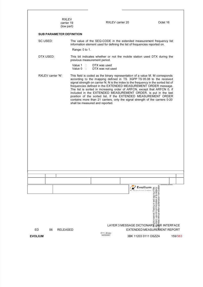
7/11/2019 1. Layer3 Air Interface Messages 0111_06
http://slidepdf.com/reader/full/1-layer3-air-interface-messages-011106 159/562
LAYER 3 MESSAGE DICTIONARY - AIR INTERFACE
ED 06 RELEASED EXTENDED MEASUREMENT REPORT
EVOLIUM
0111_06.doc14/03/2007
3BK 11203 0111 DSZZA 159/ 563
RXLEV carrier 19(low part)
RXLEV carrier 20 Octet 16
SUB PARAMETER DEFINITION
SC USED: The value of the SEQ-CODE in the extended measurement frequency list
information element used for defining the list of frequencies reported on.
Range: 0 to 1.
DTX USED: This bit indicates whether or not the mobile station used DTX during theprevious measurement period.
Value 1 : DTX was usedValue 0 : DTX was not used
RXLEV carrier 'N': This field is coded as the binary representation of a value M. M correspondsaccording to the mapping defined in TS. 3GPP TS 05.08 to the receivedsignal strength on carrier N. N is the index to the frequency in the sorted list of frequencies defined in the EXTENDED MEASUREMENT ORDER message.
The list is sorted in increasing order of ARFCN, except that ARFCN 0, if included in the EXTENDED MEASUREMENT ORDER, is put in the lastposition of the sorted list. If the EXTENDED MEASUREMENT ORDERcontains more than 21 carriers, only the signal strength of the carriers 0-20shall be measured and reported.

7/11/2019 1. Layer3 Air Interface Messages 0111_06
http://slidepdf.com/reader/full/1-layer3-air-interface-messages-011106 160/562
LAYER 3 MESSAGE DICTIONARY - AIR INTERFACE
ED 06 RELEASED GPRS SUSPENSION REQUEST
EVOLIUM
0111_06.doc14/03/2007
3BK 11203 0111 DSZZA 160/ 563
6.18 GPRS SUSPENSION REQUEST
NAME GPRS SUSPENSION REQUEST
INTERFACE RADIO ABIS A
CHANNEL/ USAGE
SDCCH/FACCH
3GPP-REF 44.018
FUNCTION The MS sends this message to the network to request a suspension of GPRSservices.
DIRECTION From: MS To: BTS
INFORMATION ELEMENT NAME TYPE COMMENT LENGTH(byte)
INFORMATIONELEMENT
LISTHeader TLLIRouting Area IdentificationSuspension cause
M V M V M V
2461
IMPLEMENTATION MAXIMUM LENGTH (byte) 13
NORMAL SITUATION ABNORMAL SITUATION TIMER
FOLLOWING
EVENT
The BSC sends the MS-
SUSPEND message to the MFS.
SPECIFDOC. REF.
Radio and Link Establishment (ref. [2])FBS GPRS - MFS-BSC interface - BSCGP layer (ref. [32])FBS GPRS - Gb interface - BSSGP layer (ref. [33])
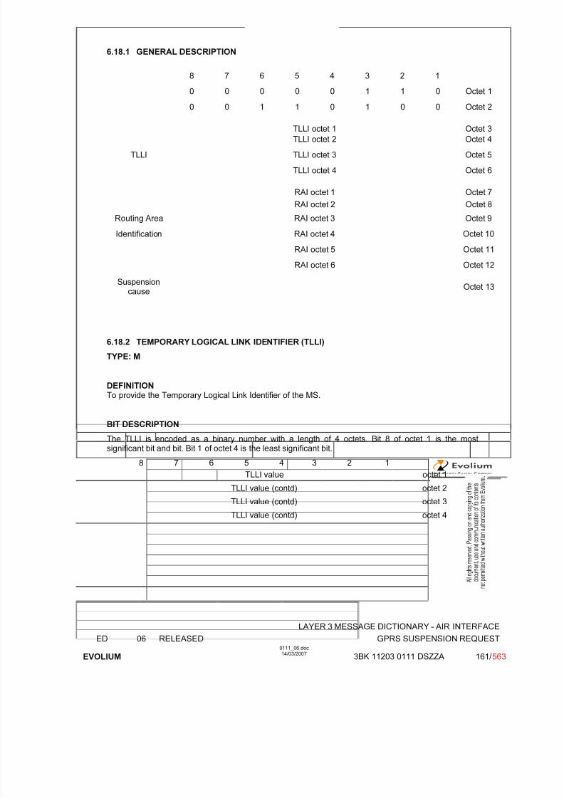
7/11/2019 1. Layer3 Air Interface Messages 0111_06
http://slidepdf.com/reader/full/1-layer3-air-interface-messages-011106 161/562
LAYER 3 MESSAGE DICTIONARY - AIR INTERFACE
ED 06 RELEASED GPRS SUSPENSION REQUEST
EVOLIUM
0111_06.doc14/03/2007
3BK 11203 0111 DSZZA 161/ 563
6.18.1 GENERAL DESCRIPTION
8 7 6 5 4 3 2 1
0 0 0 0 0 1 1 0 Octet 1
0 0 1 1 0 1 0 0 Octet 2
TLLI octet 1 Octet 3
TLLI octet 2 Octet 4
TLLI TLLI octet 3 Octet 5
TLLI octet 4 Octet 6
RAI octet 1 Octet 7
RAI octet 2 Octet 8
Routing Area RAI octet 3 Octet 9
Identification RAI octet 4 Octet 10
RAI octet 5 Octet 11
RAI octet 6 Octet 12
Suspensioncause
Octet 13
6.18.2 TEMPORARY LOGICAL LINK IDENTIFIER (TLLI)
TYPE: M
DEFINITIONTo provide the Temporary Logical Link Identifier of the MS.
BIT DESCRIPTION
The TLLI is encoded as a binary number with a length of 4 octets. Bit 8 of octet 1 is the mostsignificant bit and bit. Bit 1 of octet 4 is the least significant bit.
8 7 6 5 4 3 2 1
TLLI value octet 1
TLLI value (contd) octet 2TLLI value (contd) octet 3
TLLI value (contd) octet 4

7/11/2019 1. Layer3 Air Interface Messages 0111_06
http://slidepdf.com/reader/full/1-layer3-air-interface-messages-011106 162/562
LAYER 3 MESSAGE DICTIONARY - AIR INTERFACE
ED 06 RELEASED GPRS SUSPENSION REQUEST
EVOLIUM
0111_06.doc14/03/2007
3BK 11203 0111 DSZZA 162/ 563
6.18.3 ROUTING AREA IDENTIFICATION (RAI)
TYPE: M
DEFINITIONTo provide an unambiguous identification of routing areas within the GPRS coverage area.
BIT DESCRIPTION
8 7 6 5 4 3 2 1
MCC digit 2 MCC digit 1 octet 1
MNC digit 3 MCC digit 3 octet 2
MNC digit 2 MNC digit 1 octet 3
LAC octet 4
LAC cont'd octet 5
RAC octet 6
SUB PARAMETER DEFINITION
MCC (Mobile country code): The MCC field is coded as in ITU-T Rec. E212, Annex A.
MNC (Mobile network code): 3 digits MNC is supported. Note that in case where only two digitsMNC is used, the field “MNC Digit 3” shall be filled in with “1111”.
LAC (Location area code): Bit 8 of octet 4 is the most significant bit and bit 1 of octet 5 the leastsignificant bit.
RAC (Routing area code): Bit 8 of octet 6 is the most significant. Coding using full hexadecimal

7/11/2019 1. Layer3 Air Interface Messages 0111_06
http://slidepdf.com/reader/full/1-layer3-air-interface-messages-011106 163/562
LAYER 3 MESSAGE DICTIONARY - AIR INTERFACE
ED 06 RELEASED GPRS SUSPENSION REQUEST
EVOLIUM
0111_06.doc14/03/2007
3BK 11203 0111 DSZZA 163/ 563
6.18.4 SUSPENSION CAUSE
TYPE: M
DEFINITIONTo provide the reason for the GPRS suspension.
BIT DESCRIPTION
8 7 6 5 4 3 2 1
Suspension cause value octet 1
SUB PARAMETER DEFINITION
Suspension cause value:Bits 8 7 6 5 4 3 2 1
0 0 0 0 0 0 0 0 Emergency call, mobile originating call or call re-establishment
0 0 0 0 0 0 0 1 Location Area Update0 0 0 0 0 0 1 0 MO Short message service0 0 0 0 0 0 1 1 Other procedure which can be completed with an
SDCCH0 0 0 0 0 1 0 0 MO Voice broadcast or group call Not supported by the
Alcatel BSS0 0 0 0 0 1 0 1 Mobile terminating CS connection0 0 0 0 0 1 1 0 DTM not supported in the cell Not supported by the
Alcatel BSS
All other cause values shall be treated as 00000000
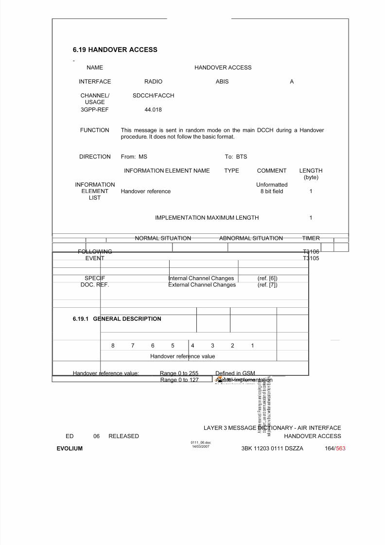
7/11/2019 1. Layer3 Air Interface Messages 0111_06
http://slidepdf.com/reader/full/1-layer3-air-interface-messages-011106 164/562
LAYER 3 MESSAGE DICTIONARY - AIR INTERFACE
ED 06 RELEASED HANDOVER ACCESS
EVOLIUM
0111_06.doc14/03/2007
3BK 11203 0111 DSZZA 164/ 563
6.19 HANDOVER ACCESS
-
NAME HANDOVER ACCESS
INTERFACE RADIO ABIS A
CHANNEL/ USAGE
SDCCH/FACCH
3GPP-REF 44.018
FUNCTION This message is sent in random mode on the main DCCH during a Handover procedure. It does not follow the basic format.
DIRECTION From: MS To: BTS
INFORMATION ELEMENT NAME TYPE COMMENT LENGTH(byte)
INFORMATIONELEMENT
LISTHandover reference
Unformatted8 bit field 1
IMPLEMENTATION MAXIMUM LENGTH 1
NORMAL SITUATION ABNORMAL SITUATION TIMER
FOLLOWINGEVENT
T3106T3105
SPECIFDOC. REF.
Internal Channel Changes (ref. [6])External Channel Changes (ref. [7])
6.19.1 GENERAL DESCRIPTION
8 7 6 5 4 3 2 1
Handover reference value
Handover reference value: Range 0 to 255 Defined in GSMRange 0 to 127 Alcatel Implementation

7/11/2019 1. Layer3 Air Interface Messages 0111_06
http://slidepdf.com/reader/full/1-layer3-air-interface-messages-011106 165/562
LAYER 3 MESSAGE DICTIONARY - AIR INTERFACE
ED 06 RELEASED HANDOVER COMMAND
EVOLIUM
0111_06.doc14/03/2007
3BK 11203 0111 DSZZA 165/ 563
6.20 HANDOVER COMMAND
NAME HANDOVER COMMAND
INTERFACE RADIO ABIS A
CHANNEL/ USAGE
SDCCH/FACCH BTS Transparent
3GPP-REF 44.018
FUNCTIONThis message is sent on the main DCCH by the network to the MS to change thededicated channel configuration.
DIRECTION From: BSC To: MS
INFORMATION ELEMENT NAME TYPE COMMENT LENGTH(byte)
IE.LIST
Header Cell DescriptionDescription of the 1st Channel, after timeHandover ReferencePower Command and access typeSynchronization Indication
Frequency Short List, after timeFrequency List, after timeCell Channel DescriptionDescription of the multislot configurationMode of the 1st Channel (Channel Set 1)Mode of Channel Set 2Mode of Channel Set 3Mode of Channel Set 4Mode of Channel Set 5Mode of Channel Set 6Mode of Channel Set 7Mode of Channel Set 8Description of the 2nd Channel, after time
Mode of the 2nd ChannelFrequency Channel Sequence, after timeMobile Allocation,after timeStarting timeReal Time DifferenceTiming AdvanceFrequency Short List, before timeFrequency List, before timeDescription of the 1st Channel, before timeChannel Description, 2nd channel beforetimeFrequency Channel Sequence, before timeMobile Allocation, before time
Cipher Mode SettingVGCS target mode IndicationMultiRate configurationDynamic ARFCN Mapping
M V M V M V M V O TV
C TV C TLV C TV C TLV O TV O TV O TV O TV O TV O TV O TV O TV O TV
O TV C TV CTLV O TV C TLV C TV C TV C TLV O TV O TV C TV C TLV O TV
O TLV O TLV O TLV
(10)
(4)
(1)(1)(5)
(3)Not usedNot usedNot usedNot usedNot usedNot usedNot usedNot used
Not used(6) (7)Not usedNot usedNot UsedNot UsedNot UsedNot UsedNot UsedNot UsedNot Used(2)
Not Used(9)Not Used
223111
104-131
173-12
222222224
210
3-1033210
4-1314410
3-101
34-8
6-34
IMPLEMENTATION MAXIMUM LENGTH (8)
NORMAL SITUATION ABNORMAL SITUATION TIMER
FOLLOWINGEVENT
Access on new channel No access T8
SPECIFDOC. REF.
Internal Channel Changes (ref. [6])External Channel Changes (ref. [7])
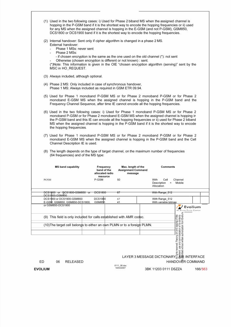
7/11/2019 1. Layer3 Air Interface Messages 0111_06
http://slidepdf.com/reader/full/1-layer3-air-interface-messages-011106 166/562
LAYER 3 MESSAGE DICTIONARY - AIR INTERFACE
ED 06 RELEASED HANDOVER COMMAND
EVOLIUM
0111_06.doc14/03/2007
3BK 11203 0111 DSZZA 166/ 563
(1) Used in the two following cases: i) Used for Phase 2 biband MS when the assigned channel ishopping in the P-GSM band if it is the shortest way to encode the hopping frequencies or ii) usedfor any MS when the assigned channel is hopping in the E-GSM (and not P-GSM), GSM850,DCS1800 or DCS1900 band if it is the shortest way to encode the hopping frequencies.
(2) Internal handover: Sent only if cipher algorithm is changed in a phase 2 MS.External handover:-
Phase 1 MSs: never sent- Phase 2 MSs:
- if chosen encryption is the same as the one used on the old channel (*): not sent- Otherwise (chosen encryption is different or not known) : sent.(*)Note: This information is given in the OIE “chosen encryption algorithm (serving)” sent by theMSC in HO_REQUEST.
(3) Always included, although optional.
(4) Phase 2 MS: Only included in case of synchronous handover,Phase 1 MS: Always included as required in GSM ETR 09.94.
(5) Used for Phase 1 monoband P-GSM MS or for Phase 2 monoband P-GSM or for Phase 2
monoband E-GSM MS when the assigned channel is hopping in the P-GSM band and theFrequency Channel Sequence, after time IE cannot encode all the hopping frequencies.
(6) Used in the two following cases: i) Used for Phase 1 monoband P-GSM MS or for Phase 2monoband P-GSM or for Phase 2 monoband E-GSM MS when the assigned channel is hopping inthe P-GSM band and this IE can encode all the hopping frequencies or ii) used for Phase 2 bibandMS when the assigned channel is hopping in the P-GSM band if it is the shortest way to encodethe hopping frequencies.
(7) Used for Phase 1 monoband P-GSM MS or for Phase 2 monoband P-GSM or for Phase 2monoband E-GSM MS when the assigned channel is hopping in the P-GSM band and the CellChannel Description IE is used.
(8) The length depends on the type of target channel, on the maximum number of frequencies(64 frequencies) and of the MS type:
MS band capability Frequency
band of theallocated radio
resource
Max. length of the
Assignment Commandmessage
Comments
PGSM P-GSM 50 With Cell Channel
Description + Mobile Allocation
DCS1800 or DCS1800-GSM850 or DCS1800-GSM900
DCS1800 67 With Range_512
DCS1900 or DCS1900-GSM850 DCS1900 67 With Range_512
E-GSM, GSM850, GSM850-DCS1800,or GSM850-DCS1900
GSM850 41 With variable bitmap
(9) This field is only included for calls established with AMR codec.
(10) The target cell belongs to either an own PLMN or to a foreign PLMN.

7/11/2019 1. Layer3 Air Interface Messages 0111_06
http://slidepdf.com/reader/full/1-layer3-air-interface-messages-011106 167/562
LAYER 3 MESSAGE DICTIONARY - AIR INTERFACE
ED 06 RELEASED HANDOVER COMMAND
EVOLIUM
0111_06.doc14/03/2007
3BK 11203 0111 DSZZA 167/ 563
6.20.1 GENERAL DESCRIPTION
6.20.1.1 Assigned channel in the P-GSM band
6.20.1.1.1 Phase 1 monoband P-GSM MS
The assigned channel is assumed hopping on more than one frequency in the P-GSM band.
a) Case the Frequency Channel Sequence, after timer IE is used
8 7 6 5 4 3 2 1
0 0 0 0 0 1 1 0
0 0 1 0 1 0 1 1
Cell
BCCH ARFCN(High Part)
NCC BCC
Description BCCH ARFCN (Low part)
Channel type and TDMA offset TN
TSCH=1-> MAIO (high part)
Channel H=0-> spare ARFCN (Hpart)
Description MAIO low part H S N
A R F C N (low part)
Handover reference HANDOVER REFERENCE
Power Command ATC 0 0 Power level
Sync. Ind. 1 1 0 1 NCI ROT SI optional
Channel 0 1 1 0 0 0 1 1optional
Mode Mode
0 1 1 0 1 0 0 1
Frequency 0 Lowest ARFCN
Channel inc skip of ARFCN 1 inc skip of ARFCN 2 optional
Sequence
inc skip of ARFCN 15 inc skip of ARFCN 16
Cipher Mode Setting 1 0 0 1 Algorithm identifier SC optional
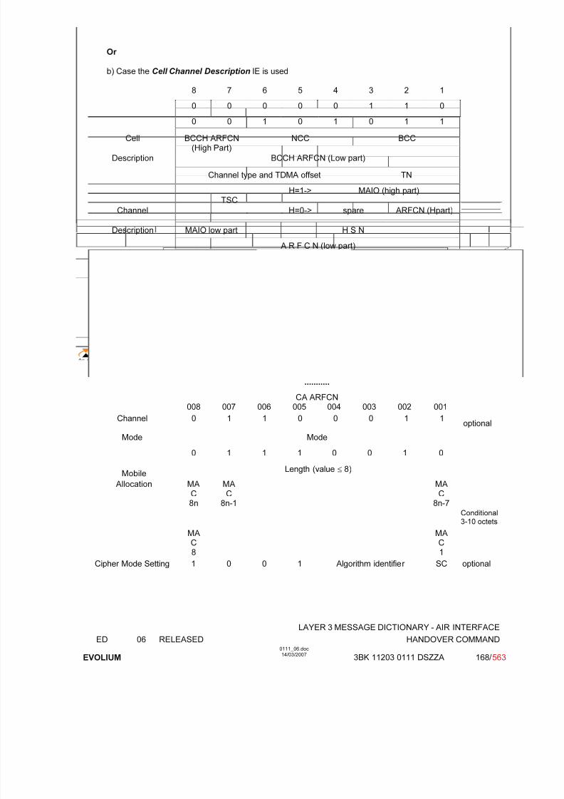
7/11/2019 1. Layer3 Air Interface Messages 0111_06
http://slidepdf.com/reader/full/1-layer3-air-interface-messages-011106 168/562
LAYER 3 MESSAGE DICTIONARY - AIR INTERFACE
ED 06 RELEASED HANDOVER COMMAND
EVOLIUM
0111_06.doc14/03/2007
3BK 11203 0111 DSZZA 168/ 563
Or
b) Case the Cell Channel Description IE is used
8 7 6 5 4 3 2 1
0 0 0 0 0 1 1 0
0 0 1 0 1 0 1 1
Cell BCCH ARFCN(High Part)
NCC BCC
Description BCCH ARFCN (Low part)
Channel type and TDMA offset TN
TSCH=1-> MAIO (high part)
Channel H=0-> spare ARFCN (Hpart)
Description MAIO low part H S N
A R F C N (low part)
Handover reference HANDOVER REFERENCE
Power Command ATC 0 0 Power level
Sync. Ind. 1 1 0 1 NCI ROT SI optional
0 1 1 0 0 0 1 0
Cell Channel
0 0FORMAT-ID
0 0 124CA
ARFCN
123 122 121
Description
120
CA ARFCN
......................... 113
Optional
17 octets...........
CA ARFCN008 007 006 005 004 003 002 001
Channel 0 1 1 0 0 0 1 1optional
Mode Mode
0 1 1 1 0 0 1 0
MobileLength (value ≤ 8)
Allocation MA
C8n
MA
C8n-1
MA
C8n-7
Conditional3-10 octets
MAC8
MAC1
Cipher Mode Setting 1 0 0 1 Algorithm identifier SC optional
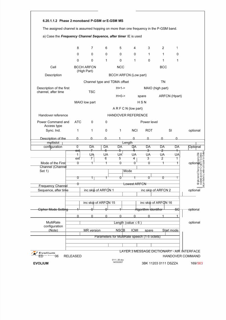
7/11/2019 1. Layer3 Air Interface Messages 0111_06
http://slidepdf.com/reader/full/1-layer3-air-interface-messages-011106 169/562
LAYER 3 MESSAGE DICTIONARY - AIR INTERFACE
ED 06 RELEASED HANDOVER COMMAND
EVOLIUM
0111_06.doc14/03/2007
3BK 11203 0111 DSZZA 169/ 563
6.20.1.1.2 Phase 2 monoband P-GSM or E-GSM MS
The assigned channel is assumed hopping on more than one frequency in the P-GSM band.
a) Case the Frequency Channel Sequence, after timer IE is used
8 7 6 5 4 3 2 10 0 0 0 0 1 1 0
0 0 1 0 1 0 1 1
Cell BCCH ARFCN(High Part)
NCC BCC
Description BCCH ARFCN (Low part)
Channel type and TDMA offset TN
Description of the firstchannel, after time TSC
H=1-> MAIO (high part)
H=0-> spare ARFCN (Hpart)
MAIO low part H S N
A R F C N (low part)
Handover reference HANDOVER REFERENCE
Power Command andAccess type
ATC 0 0 Power level
Sync. Ind. 1 1 0 1 NCI ROT SI optional
Description of the 0 0 0 1 0 0 0 0
multislot Length
configuration 0ext DA7 DA6 DA5 DA4 DA3 DA2 DA1 Optional
1ext
UA7
UA6
UA5
UA4
UA3
UA2
UA1
Mode of the FirstChannel (Channel
0 1 1 0 0 0 1 1 optional
Set 1) Mode
0 1 1 0 1 0 0 1
Frequency Channel0 Lowest ARFCN
Sequence, after time inc skip of ARFCN 1 inc skip of ARFCN 2 optional
inc skip of ARFCN 15 inc skip of ARFCN 16
Cipher Mode Setting 1 0 0 1 Algorithm identifier SC optional
0 0 0 0 0 0 1 1
MultiRateconfiguration
Length (value ≤ 6 ) optional
(Note) MR version NSCB ICMI spare Start mode
Parameters for MultiRate speech (1-5 octets)
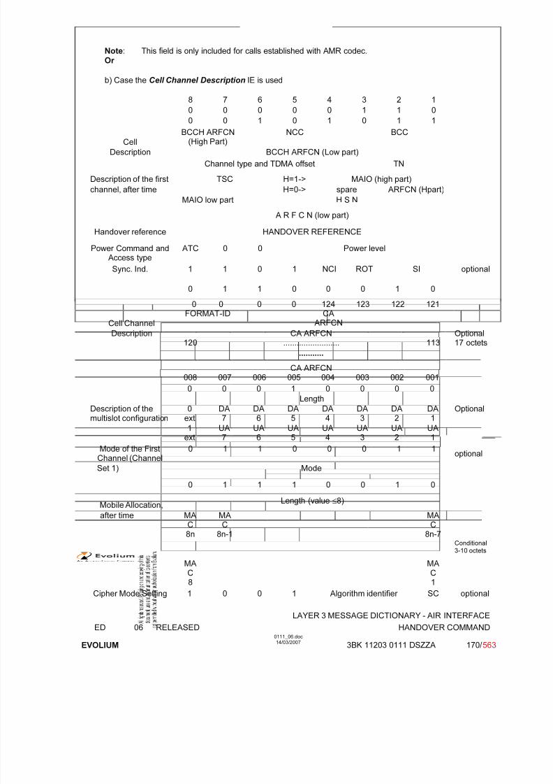
7/11/2019 1. Layer3 Air Interface Messages 0111_06
http://slidepdf.com/reader/full/1-layer3-air-interface-messages-011106 170/562
LAYER 3 MESSAGE DICTIONARY - AIR INTERFACE
ED 06 RELEASED HANDOVER COMMAND
EVOLIUM
0111_06.doc14/03/2007
3BK 11203 0111 DSZZA 170/ 563
Note: This field is only included for calls established with AMR codec.Or
b) Case the Cell Channel Description IE is used
8 7 6 5 4 3 2 1
0 0 0 0 0 1 1 0
0 0 1 0 1 0 1 1
Cell
BCCH ARFCN(High Part)
NCC BCC
Description BCCH ARFCN (Low part)
Channel type and TDMA offset TN
Description of the first TSC H=1-> MAIO (high part)
channel, after time H=0-> spare ARFCN (Hpart)
MAIO low part H S N
A R F C N (low part)
Handover reference HANDOVER REFERENCE
Power Command andAccess type
ATC 0 0 Power level
Sync. Ind. 1 1 0 1 NCI ROT SI optional
0 1 1 0 0 0 1 0
Cell Channel
0 0FORMAT-ID
0 0 124CA
ARFCN
123 122 121
Description120
CA ARFCN......................... 113
Optional17 octets
...........
CA ARFCN008 007 006 005 004 003 002 001
0 0 0 1 0 0 0 0
Length
Description of themultislot configuration
0ext
DA7
DA6
DA5
DA4
DA3
DA2
DA1
Optional
1ext
UA7
UA6
UA5
UA4
UA3
UA2
UA1
Mode of the FirstChannel (Channel
0 1 1 0 0 0 1 1optional
Set 1) Mode
0 1 1 1 0 0 1 0
Mobile Allocation,Length (value ≤8)
after time MAC8n
MAC
8n-1
MAC
8n-7Conditional
3-10 octets
MAC8
MAC1
Cipher Mode Setting 1 0 0 1 Algorithm identifier SC optional

7/11/2019 1. Layer3 Air Interface Messages 0111_06
http://slidepdf.com/reader/full/1-layer3-air-interface-messages-011106 171/562
LAYER 3 MESSAGE DICTIONARY - AIR INTERFACE
ED 06 RELEASED HANDOVER COMMAND
EVOLIUM
0111_06.doc14/03/2007
3BK 11203 0111 DSZZA 171/ 563
0 0 0 0 0 0 1 1
MultiRateconfiguration
Length (value ≤ 6) optional
(Note) MR version NSCB ICMI spare Start mode
Parameters for MultiRate speech (1-5 octets)
Note: This field is only included for calls established with AMR codec.
6.20.1.1.3 Phase 2 biband MS
For phase 2 iband MS the shortest frequency encoding IE will always be used. The choice will bemade between the following CIEs:
- “Frequency Channel Sequence, after time” (as in section 6.20.1.1.2),- "Frequency Short List, after time" (as in section 6.20.1.2),- "Frequency List, after time" (as in section 6.20.1.2).
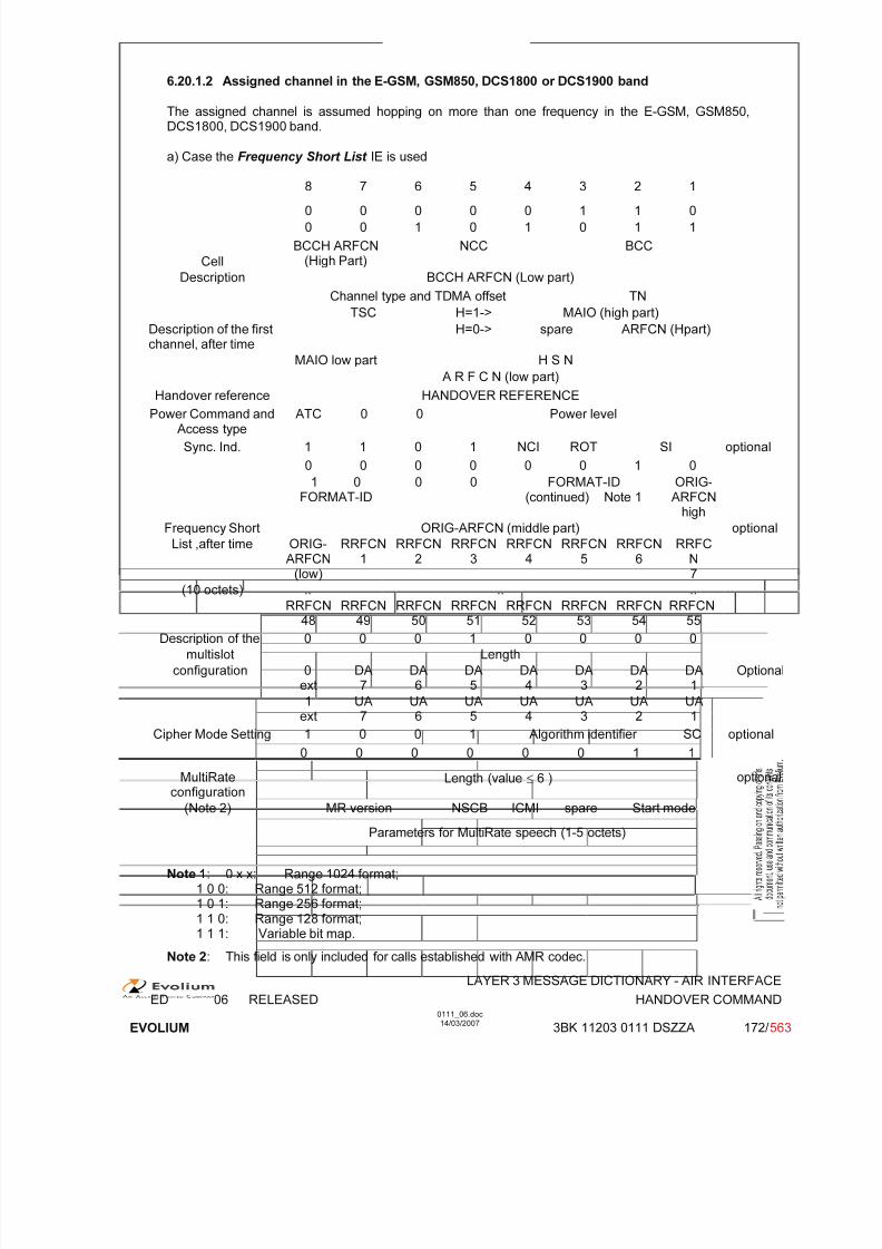
7/11/2019 1. Layer3 Air Interface Messages 0111_06
http://slidepdf.com/reader/full/1-layer3-air-interface-messages-011106 172/562
LAYER 3 MESSAGE DICTIONARY - AIR INTERFACE
ED 06 RELEASED HANDOVER COMMAND
EVOLIUM
0111_06.doc14/03/2007
3BK 11203 0111 DSZZA 172/ 563
6.20.1.2 Assigned channel in the E-GSM, GSM850, DCS1800 or DCS1900 band
The assigned channel is assumed hopping on more than one frequency in the E-GSM, GSM850,DCS1800, DCS1900 band.
a) Case the Frequency Short List IE is used
8 7 6 5 4 3 2 10 0 0 0 0 1 1 0
0 0 1 0 1 0 1 1
Cell
BCCH ARFCN(High Part)
NCC BCC
Description BCCH ARFCN (Low part)
Channel type and TDMA offset TN
TSC H=1-> MAIO (high part)
Description of the firstchannel, after time
H=0-> spare ARFCN (Hpart)
MAIO low part H S N
A R F C N (low part)
Handover reference HANDOVER REFERENCE
Power Command andAccess type
ATC 0 0 Power level
Sync. Ind. 1 1 0 1 NCI ROT SI optional
0 0 0 0 0 0 1 0
1 0FORMAT-ID
0 0 FORMAT-ID(continued) Note 1
ORIG-ARFCN
high
Frequency Short ORIG-ARFCN (middle part) optional
List ,after time ORIG-ARFCN
(low)
RRFCN1
RRFCN2
RRFCN3
RRFCN4
RRFCN5
RRFCN6
RRFCN
7(10 octets) .. .. ..
RRFCN48
RRFCN49
RRFCN50
RRFCN51
RRFCN52
RRFCN53
RRFCN54
RRFCN55
Description of the 0 0 0 1 0 0 0 0
multislot Length
configuration 0ext
DA7
DA6
DA5
DA4
DA3
DA2
DA1
Optional
1ext
UA7
UA6
UA5
UA4
UA3
UA2
UA1
Cipher Mode Setting 1 0 0 1 Algorithm identifier SC optional
0 0 0 0 0 0 1 1
MultiRateconfiguration
Length (value ≤ 6 ) optional
(Note 2) MR version NSCB ICMI spare Start mode
Parameters for MultiRate speech (1-5 octets)
Note 1: 0 x x: Range 1024 format;1 0 0: Range 512 format;1 0 1: Range 256 format;1 1 0: Range 128 format;1 1 1: Variable bit map.
Note 2: This field is only included for calls established with AMR codec.

7/11/2019 1. Layer3 Air Interface Messages 0111_06
http://slidepdf.com/reader/full/1-layer3-air-interface-messages-011106 173/562
LAYER 3 MESSAGE DICTIONARY - AIR INTERFACE
ED 06 RELEASED HANDOVER COMMAND
EVOLIUM
0111_06.doc14/03/2007
3BK 11203 0111 DSZZA 173/ 563
Or
b) Case the Frequency List IE is used
8 7 6 5 4 3 2 1
0 0 0 0 0 1 1 0
0 0 1 0 1 0 1 1
Cell
BCCH ARFCN(High Part)
NCC BCC
Description BCCH ARFCN (Low part)
Channel type and TDMA offset TN
Description of the firstTSC H=1-> MAIO (high part)
channel, after time H=0-> spare ARFCN (Hpart)
MAIO low part H S N
A R F C N (low part)
Handover reference HANDOVER REFERENCE
Power Command andAccess type
ATC 0 0 Power level
Sync. Ind. 1 1 0 1 NCI ROT SI optional
0 0 1 0 1 0 0 1 0 0 1 1 0
Length of frequency list contents
1 0FORMAT-ID
0 0 1 1 1FORMAT-ID(continued)
ORIG-ARFCN
high
Frequency ORIG-ARFCN (middle part) optional
List ,after time ORIG-ARFCN
(low)
RRFCN1
RRFCN2
RRFCN3
RRFCN4
RRFCN5
RRFCN6
RRFCN7
.. .. ..
Note 1 RRFCN8k-40
RRFCN8k-39
RRFCN8k-38
RRFCN8k-37
RRFCN8k-36
RRFCN8k-35
RRFCN8k-34
RRFCN
8k-33
Description of the 0 0 0 1 0 0 0 0
multislot Length
configuration 0ext
DA7
DA6
DA5
DA4
DA3
DA2
DA1
Optional
1ext
UA7
UA6
UA5
UA4
UA3
UA2
UA1
Cipher Mode Setting 1 0 0 1 Algorithm identifier SC optional
0 0 0 0 0 0 1 1
MultiRateconfiguration
Length (value ≤ 6 ) optional
(Note) MR version NSCB ICMI spare Start mode
Parameters for MultiRate speech (1-5 octets)
Notes :
1) k indicates the octet number of the I.E. Frequency List, after time. k ≤ 131.2)
2) This field is only included for calls established with AMR codec.
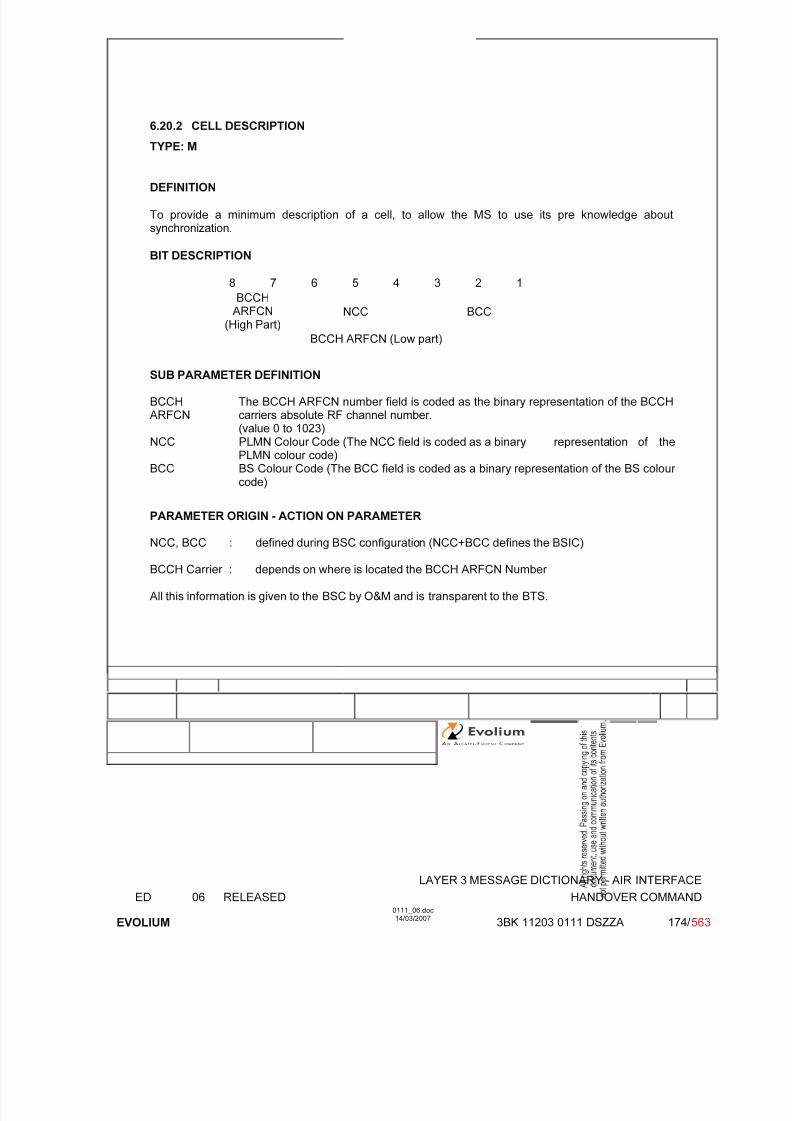
7/11/2019 1. Layer3 Air Interface Messages 0111_06
http://slidepdf.com/reader/full/1-layer3-air-interface-messages-011106 174/562
LAYER 3 MESSAGE DICTIONARY - AIR INTERFACE
ED 06 RELEASED HANDOVER COMMAND
EVOLIUM
0111_06.doc14/03/2007
3BK 11203 0111 DSZZA 174/ 563
6.20.2 CELL DESCRIPTION
TYPE: M
DEFINITION
To provide a minimum description of a cell, to allow the MS to use its pre knowledge aboutsynchronization.
BIT DESCRIPTION
8 7 6 5 4 3 2 1
BCCHARFCN
(High Part)NCC BCC
BCCH ARFCN (Low part)
SUB PARAMETER DEFINITION
BCCHARFCN
The BCCH ARFCN number field is coded as the binary representation of the BCCHcarriers absolute RF channel number.(value 0 to 1023)
NCC PLMN Colour Code (The NCC field is coded as a binary representation of thePLMN colour code)
BCC BS Colour Code (The BCC field is coded as a binary representation of the BS colour code)
PARAMETER ORIGIN - ACTION ON PARAMETER
NCC, BCC : defined during BSC configuration (NCC+BCC defines the BSIC)
BCCH Carrier : depends on where is located the BCCH ARFCN Number
All this information is given to the BSC by O&M and is transparent to the BTS.

7/11/2019 1. Layer3 Air Interface Messages 0111_06
http://slidepdf.com/reader/full/1-layer3-air-interface-messages-011106 175/562
LAYER 3 MESSAGE DICTIONARY - AIR INTERFACE
ED 06 RELEASED HANDOVER COMMAND
EVOLIUM
0111_06.doc14/03/2007
3BK 11203 0111 DSZZA 175/ 563
6.20.3 Channel Description / CHANNEL DESCRIPTION - Phase 1
TYPE: M
DEFINITION
To provide a description of an allocatable channel together with its SACCH.
BIT DESCRIPTION
8 7 6 5 4 3 2 1
Channel type and TDMA offset TN 1
TSCH=1-> MAIO (high part) 2
H=0-> spare ARFCN (Hpart)
MAIO low part H S N 3A R F C N (low part)
SUB PARAMETER DEFINITION
Octet 1
Channel type and TDMA offset.
Bits 8 7 6 5 40 0 0 0 1 TCH/F + ACCHs0 0 0 1 T TCH/H + ACCHs
0 0 1 T T SDCCH/4 + SACCH/C4 or CBCH (SDCCH/4)0 1 T T T SDCCH/8 + SACCH/C8 or CBCH (SDCCH/8)all other values are reserved.
T bit indicates the Subchannel Number.
TN : Time slot (0 to 7)
Octets 2 and 3:
TSC : Training Sequence Code (0 to 7)
H : "0" Single RF channel
"1" RF hopping channel

7/11/2019 1. Layer3 Air Interface Messages 0111_06
http://slidepdf.com/reader/full/1-layer3-air-interface-messages-011106 176/562
LAYER 3 MESSAGE DICTIONARY - AIR INTERFACE
ED 06 RELEASED HANDOVER COMMAND
EVOLIUM
0111_06.doc14/03/2007
3BK 11203 0111 DSZZA 176/ 563
Channel selector:
H = "0": The channel selector field consists of the absolute RF channel number.Bits 4 3
0 0 spare
ARFCN:
Octet2 Bits 2,1 High part of ARFCNOctet 3 Bits 8 to 1 ARFCN low part
The ARFCN is coded as the binary representation of the absolute RF channelNumber.
Range 0 to 1023.
H = "1": The channel selector field consists of the mobile allocation index offset, MAIO, and thehopping sequence number, HSN.
MAIO:
Octet 2 Bits 4 to 1 High partOctet 3 Bits 8 to 7 Low part
HSN (Octet 3, Bits 1 to 6):Value 0 to 63.
The HSN field is coded as the binary representation of the hopping sequence number.
PARAMETER ORIGIN - ACTION ON PARAMETER
This parameter is transparent for the BTS when received.
At the BSC site, the BSC has to provide the following information:
• Channel type and TDMA offset and TN depends of the resource to be allocated by theresource manager.
• H: fixed value according if hopping is used or not (this information has to be provided by O&M).
• Channel selector.

7/11/2019 1. Layer3 Air Interface Messages 0111_06
http://slidepdf.com/reader/full/1-layer3-air-interface-messages-011106 177/562
LAYER 3 MESSAGE DICTIONARY - AIR INTERFACE
ED 06 RELEASED HANDOVER COMMAND
EVOLIUM
0111_06.doc14/03/2007
3BK 11203 0111 DSZZA 177/ 563
6.20.4 Description of the first channel, after time / CHANNEL DESCRIPTION 2 - Phase 2
TYPE: M
DEFINITION
To provide a description of an allocatable channel together with its SACCH.
BIT DESCRIPTION
8 7 6 5 4 3 2 1
Channel type and TDMA offset TN 1
TSCH=1-> MAIO (high part) 2
H=0-> spare ARFCN (Hpart)
MAIO low part H S N 3
A R F C N (low part)
SUB PARAMETER DEFINITION
Octet 1
Channel type and TDMA offset.Bits 8 7 6 5 4
0 0 0 0 0 TCH/F + FACCH/F and SACCH/M at the timeslot indicated by TN,and additional bidirectional or undirectional TCH/Fs and SACCH/Msaccording to the multislot allocation information element
0 0 0 0 1 TCH/F + FACCH/F and SACCH/F
0 0 0 1 T TCH/H + ACCHs0 0 1 T T SDCCH/4 + SACCH/C4 or CBCH (SDCCH/4)0 1 T T T SDCCH/8 + SACCH/C8 or CBCH (SDCCH/8)In the description below "n" is the timeslot number indicated by TN. The description isvalid only if all the indicated timeslot numbers are in the rang 0 to 7.1 0 X X X TCH/F + FACCH/F and SACCH/M at the time slot indicated by TN,
and additional bidirectional TCH/Fs and SACCH/Ms at other timeslots according to the following:
X X X:0 0 0 no additional timeslots0 0 1 at timeslot n-10 1 0 at timeslot n+1, n-10 1 1 at timeslot n+1, n-1 and n-2
1 0 0 at timeslot n+1, n-1, n-2, and n-31 0 1 at timeslot n+1, n-1, n-2, n-3 and n-41 1 0 at timeslot n+1, n-1, n-2, n-3, n-4 and n-51 1 1 at timeslot n+1, n-1, n-2, n-3, n-4, n-5 and n-6
1 1 0 0 1to1 1 0 1 1
TCH/F + FACCH/F and SACCH/M at the time slot indicated by TNand additiona unidirectional TCH/FDs and SACCH/MDs at other timeslots according to the following:
1 1 0 0 1 at timeslot n-11 1 0 1 0 at timeslot n+1, n-11 1 0 1 1 at timeslot n+1, n-1 and n-21 1 1 1 0 TCH/F + FACCH/F and SACCH/M at the time slot indicated by TN
and additional bidirectional TCH/F and SACCH/M at timeslot n+1 andunidirectional TCH/FD and SACCH/MD at timeslot n-1

7/11/2019 1. Layer3 Air Interface Messages 0111_06
http://slidepdf.com/reader/full/1-layer3-air-interface-messages-011106 178/562
LAYER 3 MESSAGE DICTIONARY - AIR INTERFACE
ED 06 RELEASED HANDOVER COMMAND
EVOLIUM
0111_06.doc14/03/2007
3BK 11203 0111 DSZZA 178/ 563
All other values are reserved.T bit indicates the Subchannel Number
TN : Time slot (0 to 7)
Octets 2 and 3:
TSC : Training Sequence Code (0 to 7)
H : "0" Single RF channel"1" RF hopping channel
Channel selector:
H = "0": The channel selector field consists of the absolute RF channel number.Bits 4 3
0 0 spare
ARFCN:
Octet 2 Bits 2,1 High part of ARFCNOctet 3 Bits 8 to 1 ARFCN low part
The ARFCN is coded as the binary representation of the absolute RF channelNumber.
Range 0 to 1023.
H = "1": The channel selector field consists of the mobile allocation index offset, MAIO, and thehopping sequence number, HSN.
MAIO:
Octet 2 Bits 4 to 1 High partOctet 3 Bits 8 to 7 Low part
HSN (Octet 3, Bits 1 to 6):Value 0 to 63.
The HSN field is coded as the binary representation of the hopping sequence number.
PARAMETER ORIGIN - ACTION ON PARAMETER
This parameter is transparent for the BTS when received.
At the BSC site, the BSC has to provide the following information:
• Channel type and TDMA offset and TN depends of the resource to be allocated by theresource manager.
• H: fixed value according if hopping is used or not (this information has to be provided by O&M).
• Channel selector.

7/11/2019 1. Layer3 Air Interface Messages 0111_06
http://slidepdf.com/reader/full/1-layer3-air-interface-messages-011106 179/562
LAYER 3 MESSAGE DICTIONARY - AIR INTERFACE
ED 06 RELEASED HANDOVER COMMAND
EVOLIUM
0111_06.doc14/03/2007
3BK 11203 0111 DSZZA 179/ 563
6.20.5 HANDOVER REFERENCE
TYPE: M
DEFINITIONTo provide an Handover reference value used for access identification.
BIT DESCRIPTION
8 7 6 5 4 3 2 1
HANDOVER REF. VALUE
SUB PARAMETER DEFINITION
Handover reference value: Range 0 to 255 Defined in GSMRange 0 to 127 Alcatel Implementation.Binary coding.
PARAMETER ORIGIN - ACTION ON PARAMETER
The old BSC is transparent on this parameter (this information is given to the old BSC by MSC in theHandover Command message). This reference has been allocated by the new BSC during Handover initialisation (refer to Handover Request Ack message).

7/11/2019 1. Layer3 Air Interface Messages 0111_06
http://slidepdf.com/reader/full/1-layer3-air-interface-messages-011106 180/562
LAYER 3 MESSAGE DICTIONARY - AIR INTERFACE
ED 06 RELEASED HANDOVER COMMAND
EVOLIUM
0111_06.doc14/03/2007
3BK 11203 0111 DSZZA 180/ 563
6.20.6 POWER COMMAND AND ACCESS TYPE
TYPE: M
DEFINITIONTo provide the power level for the Mobile Station
BIT DESCRIPTION
8 7 6 5 4 3 2 1
1 ATC 0 0 Power level
Bits 6 to 7 of octet 1 are spare bits (coded as 0).
SUB PARAMETER DEFINITION
ATC : set to 0 supported.
set to 1 not supported.
Power level : binary representation of the power control level(0 to 31)
GSM phase 1
Power Control
level GSM-900 DCS-1800
Peak power Binary value Peak power Binary value
0 43 dBm 0 30 dBm 0
1 41 dBm 1 28 dBm 1
2 39 dBm 2 26 dBm 23 37 dBm 3 24 dBm 3
4 35 dBm 4 22 dBm 4
5 33 dBm 5 20 dBm 5
6 31 dBm 6 18 dBm 6
7 29 dBm 7 16 dBm 7
8 27 dBm 8 14 dBm 8
9 25 dBm 9 12 dBm 9
10 23 dBm 10 10 dBm 10
11 21 dBm 11 8 dBm 11 (note 1)
12 19 dBm 12 6 dBm 12 (note 1)
13 17 dBm 13 4 dBm 13 (note 1)
14 15 dBm 1415 13 dBm 15
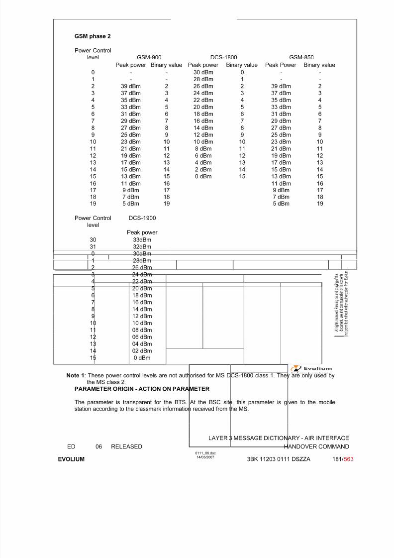
7/11/2019 1. Layer3 Air Interface Messages 0111_06
http://slidepdf.com/reader/full/1-layer3-air-interface-messages-011106 181/562
LAYER 3 MESSAGE DICTIONARY - AIR INTERFACE
ED 06 RELEASED HANDOVER COMMAND
EVOLIUM
0111_06.doc14/03/2007
3BK 11203 0111 DSZZA 181/ 563
GSM phase 2
Power Control
level GSM-900 DCS-1800 GSM-850
Peak power Binary value Peak power Binary value Peak Power Binary value
0 - - 30 dBm 0 - -
1 - - 28 dBm 1 - -
2 39 dBm 2 26 dBm 2 39 dBm 23 37 dBm 3 24 dBm 3 37 dBm 3
4 35 dBm 4 22 dBm 4 35 dBm 4
5 33 dBm 5 20 dBm 5 33 dBm 5
6 31 dBm 6 18 dBm 6 31 dBm 6
7 29 dBm 7 16 dBm 7 29 dBm 7
8 27 dBm 8 14 dBm 8 27 dBm 8
9 25 dBm 9 12 dBm 9 25 dBm 9
10 23 dBm 10 10 dBm 10 23 dBm 10
11 21 dBm 11 8 dBm 11 21 dBm 11
12 19 dBm 12 6 dBm 12 19 dBm 12
13 17 dBm 13 4 dBm 13 17 dBm 13
14 15 dBm 14 2 dBm 14 15 dBm 1415 13 dBm 15 0 dBm 15 13 dBm 15
16 11 dBm 16 11 dBm 1617 9 dBm 17 9 dBm 1718 7 dBm 18 7 dBm 1819 5 dBm 19 5 dBm 19
Power Control
level
DCS-1900
Peak power
30 33dBm
31 32dBm
0 30dBm
1 28dBm
2 26 dBm
3 24 dBm
4 22 dBm
5 20 dBm
6 18 dBm
7 16 dBm
8 14 dBm
9 12 dBm
10 10 dBm
11 08 dBm
12 06 dBm
13 04 dBm14 02 dBm
15 0 dBm
Note 1: These power control levels are not authorised for MS DCS-1800 class 1. They are only used bythe MS class 2.
PARAMETER ORIGIN - ACTION ON PARAMETER
The parameter is transparent for the BTS. At the BSC site, this parameter is given to the mobilestation according to the classmark information received from the MS.
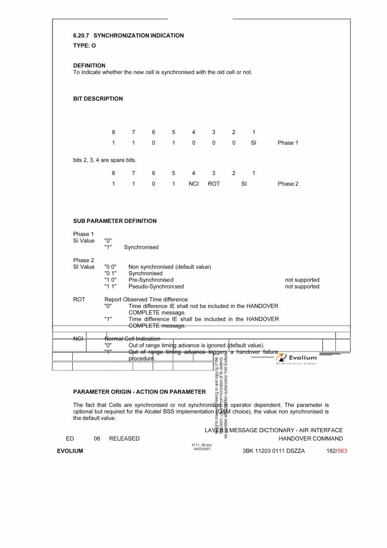
7/11/2019 1. Layer3 Air Interface Messages 0111_06
http://slidepdf.com/reader/full/1-layer3-air-interface-messages-011106 182/562
LAYER 3 MESSAGE DICTIONARY - AIR INTERFACE
ED 06 RELEASED HANDOVER COMMAND
EVOLIUM
0111_06.doc14/03/2007
3BK 11203 0111 DSZZA 182/ 563
6.20.7 SYNCHRONIZATION INDICATION
TYPE: O
DEFINITIONTo indicate whether the new cell is synchronised with the old cell or not.
BIT DESCRIPTION
8 7 6 5 4 3 2 1
1 1 0 1 0 0 0 SI Phase 1
bits 2, 3, 4 are spare bits.
8 7 6 5 4 3 2 1
1 1 0 1 NCI ROT SI Phase 2
SUB PARAMETER DEFINITION
Phase 1Si Value "0"
"1" Synchronised
Phase 2SI Value "0 0" Non synchronised (default value)
"0 1" Synchronised"1 0" Pre-Synchronised not supported"1 1" Pseudo-Synchronised not supported
ROT Report Observed Time difference"0" Time difference IE shall not be included in the HANDOVER
COMPLETE message."1" Time difference IE shall be included in the HANDOVER
COMPLETE message.
NCI Normal Cell Indication"0" Out of range timing advance is ignored (default value)."1" Out of range timing advance triggers a handover failure
procedure.
PARAMETER ORIGIN - ACTION ON PARAMETER
The fact that Cells are synchronised or not synchronised is operator dependent. The parameter isoptional but required for the Alcatel BSS implementation (O&M choice), the value non synchronised isthe default value.
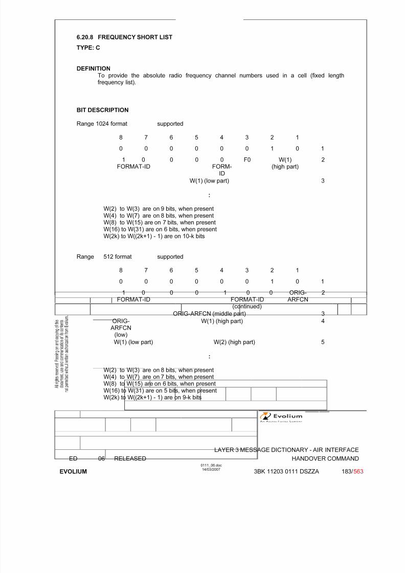
7/11/2019 1. Layer3 Air Interface Messages 0111_06
http://slidepdf.com/reader/full/1-layer3-air-interface-messages-011106 183/562
LAYER 3 MESSAGE DICTIONARY - AIR INTERFACE
ED 06 RELEASED HANDOVER COMMAND
EVOLIUM
0111_06.doc14/03/2007
3BK 11203 0111 DSZZA 183/ 563
6.20.8 FREQUENCY SHORT LIST
TYPE: C
DEFINITIONTo provide the absolute radio frequency channel numbers used in a cell (fixed lengthfrequency list).
BIT DESCRIPTION
Range 1024 format supported
8 7 6 5 4 3 2 1
0 0 0 0 0 0 1 0 1
1 0FORMAT-ID
0 0 0FORM-
ID
F0 W(1)(high part)
2
W(1) (low part) 3
:
W(2) to W(3) are on 9 bits, when presentW(4) to W(7) are on 8 bits, when presentW(8) to W(15) are on 7 bits, when presentW(16) to W(31) are on 6 bits, when presentW(2k) to W((2k+1) - 1) are on 10-k bits
Range 512 format supported
8 7 6 5 4 3 2 1
0 0 0 0 0 0 1 0 1
1 0FORMAT-ID
0 0 1 0 0FORMAT-ID(continued)
ORIG-ARFCN
2
ORIG-ARFCN (middle part) 3
ORIG-ARFCN
(low)
W(1) (high part) 4
W(1) (low part) W(2) (high part) 5
:
W(2) to W(3) are on 8 bits, when presentW(4) to W(7) are on 7 bits, when presentW(8) to W(15) are on 6 bits, when presentW(16) to W(31) are on 5 bits, when presentW(2k) to W((2k+1) - 1) are on 9-k bits

7/11/2019 1. Layer3 Air Interface Messages 0111_06
http://slidepdf.com/reader/full/1-layer3-air-interface-messages-011106 184/562
LAYER 3 MESSAGE DICTIONARY - AIR INTERFACE
ED 06 RELEASED HANDOVER COMMAND
EVOLIUM
0111_06.doc14/03/2007
3BK 11203 0111 DSZZA 184/ 563
Range 256 format supported
8 7 6 5 4 3 2 1
0 0 0 0 0 0 1 0 1
1 0FORMAT-ID
0 0 1 0 1FORMAT-ID
(continued)
ORIG-ARFCN
2
ORIG-ARFCN (middle part) 3
ORIG-ARFCN
(low)
W(1) (high part) 4
W(1)(lowpart)
W(2) 5
:
W(2) to W(3) are on 7 bits, when presentW(4) to W(7) are on 6 bits, when presentW(8) to W(15) are on 5 bits, when present
W(16) to W(31) are on 4 bits, when presentW(2k) to W((2k+1) - 1) are on 8-k bits
Range 128 format supported
8 7 6 5 4 3 2 1
0 0 0 0 0 0 1 0 1
1 0FORMAT-ID
0 0 1 1 0FORMAT-ID(continued)
ORIG-ARFCN
2
ORIG-ARFCN (middle part) 3
ORIG-ARFCN(low)
W(1) 4
:
W(2) to W(3) are on 6 bits, when presentW(4) to W(7) are on 5 bits, when presentW(8) to W(15) are on 4 bits, when presentW(16) to W(31) are on 3 bits, when presentW(2k) to W((2k+1) - 1) are on 7-k bits
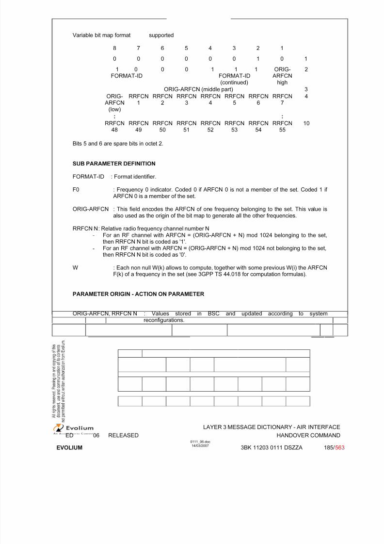
7/11/2019 1. Layer3 Air Interface Messages 0111_06
http://slidepdf.com/reader/full/1-layer3-air-interface-messages-011106 185/562
LAYER 3 MESSAGE DICTIONARY - AIR INTERFACE
ED 06 RELEASED HANDOVER COMMAND
EVOLIUM
0111_06.doc14/03/2007
3BK 11203 0111 DSZZA 185/ 563
Variable bit map format supported
8 7 6 5 4 3 2 1
0 0 0 0 0 0 1 0 1
1 0FORMAT-ID
0 0 1 1 1FORMAT-ID
(continued)
ORIG-ARFCN
high
2
ORIG-ARFCN (middle part) 3
ORIG-ARFCN
(low)
RRFCN1
RRFCN2
RRFCN3
RRFCN4
RRFCN5
RRFCN6
RRFCN7
4
: :
RRFCN48
RRFCN49
RRFCN50
RRFCN51
RRFCN52
RRFCN53
RRFCN54
RRFCN55
10
Bits 5 and 6 are spare bits in octet 2.
SUB PARAMETER DEFINITION
FORMAT-ID : Format identifier.
F0 : Frequency 0 indicator. Coded 0 if ARFCN 0 is not a member of the set. Coded 1 if ARFCN 0 is a member of the set.
ORIG-ARFCN : This field encodes the ARFCN of one frequency belonging to the set. This value isalso used as the origin of the bit map to generate all the other frequencies.
RRFCN N : Relative radio frequency channel number N- For an RF channel with ARFCN = (ORIG-ARFCN + N) mod 1024 belonging to the set,
then RRFCN N bit is coded as '1'.-
For an RF channel with ARFCN = (ORIG-ARFCN + N) mod 1024 not belonging to the set,then RRFCN N bit is coded as '0'.
W : Each non null W(k) allows to compute, together with some previous W(i) the ARFCNF(k) of a frequency in the set (see 3GPP TS 44.018 for computation formulas).
PARAMETER ORIGIN - ACTION ON PARAMETER
ORIG-ARFCN, RRFCN N : Values stored in BSC and updated according to systemreconfigurations.
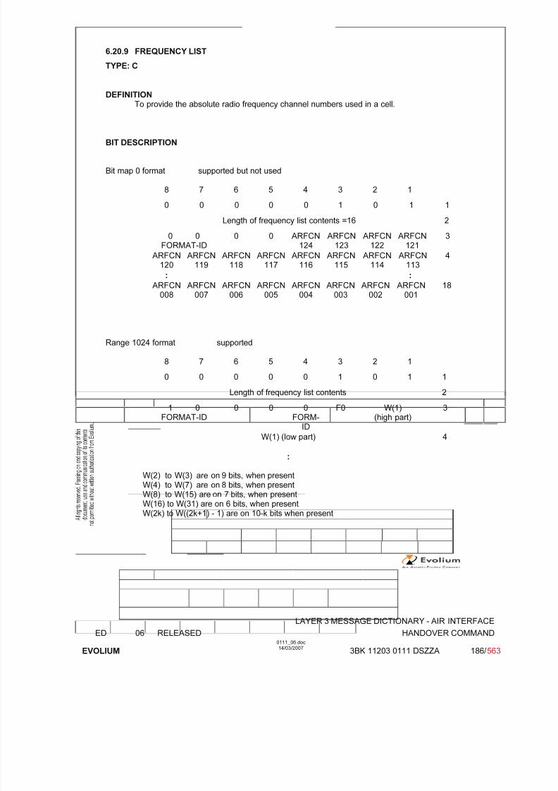
7/11/2019 1. Layer3 Air Interface Messages 0111_06
http://slidepdf.com/reader/full/1-layer3-air-interface-messages-011106 186/562
LAYER 3 MESSAGE DICTIONARY - AIR INTERFACE
ED 06 RELEASED HANDOVER COMMAND
EVOLIUM
0111_06.doc14/03/2007
3BK 11203 0111 DSZZA 186/ 563
6.20.9 FREQUENCY LIST
TYPE: C
DEFINITIONTo provide the absolute radio frequency channel numbers used in a cell.
BIT DESCRIPTION
Bit map 0 format supported but not used
8 7 6 5 4 3 2 1
0 0 0 0 0 1 0 1 1
Length of frequency list contents =16 2
0 0
FORMAT-ID
0 0 ARFCN
124
ARFCN
123
ARFCN
122
ARFCN
121
3
ARFCN120
ARFCN119
ARFCN118
ARFCN117
ARFCN116
ARFCN115
ARFCN114
ARFCN113
4
: :
ARFCN008
ARFCN007
ARFCN006
ARFCN005
ARFCN004
ARFCN003
ARFCN002
ARFCN001
18
Range 1024 format supported
8 7 6 5 4 3 2 10 0 0 0 0 1 0 1 1
Length of frequency list contents 2
1 0FORMAT-ID
0 0 0FORM-
ID
F0 W(1)(high part)
3
W(1) (low part) 4
:
W(2) to W(3) are on 9 bits, when present
W(4) to W(7) are on 8 bits, when presentW(8) to W(15) are on 7 bits, when presentW(16) to W(31) are on 6 bits, when presentW(2k) to W((2k+1) - 1) are on 10-k bits when present

7/11/2019 1. Layer3 Air Interface Messages 0111_06
http://slidepdf.com/reader/full/1-layer3-air-interface-messages-011106 187/562
LAYER 3 MESSAGE DICTIONARY - AIR INTERFACE
ED 06 RELEASED HANDOVER COMMAND
EVOLIUM
0111_06.doc14/03/2007
3BK 11203 0111 DSZZA 187/ 563
Range 512 format supported
8 7 6 5 4 3 2 1
0 0 0 0 0 1 0 1 1
Length of frequency list contents 2
1 0FORMAT-ID
0 0 1 0 0FORMAT-ID(continued)
ORIG-ARFCN
3
ORIG-ARFCN (middle part) 4
ORIG-ARFCN
(low)
W(1) (high part) 5
W(1) (low part) W(2) (high part) 6
:
W(2) to W(3) are on 8 bits, when present
W(4) to W(7) are on 7 bits, when presentW(8) to W(15) are on 6 bits, when presentW(16) to W(31) are on 5 bits, when presentW(2k) to W((2k+1) - 1) are on 9-k bits when present
Range 256 format supported
8 7 6 5 4 3 2 1
0 0 0 0 0 1 0 1 1
Length of frequency list contents 2
1 0FORMAT-ID
0 0 1 0 1FORMAT-ID(continued)
ORIG-ARFCN
3
ORIG-ARFCN (middle part) 4
ORIG-ARFCN
(low)
W(1) (high part) 5
W(1)(lowpart)
W(2) 6
:
W(2) to W(3) are on 7 bits, when presentW(4) to W(7) are on 6 bits, when presentW(8) to W(15) are on 5 bits, when presentW(16) to W(31) are on 4 bits, when presentW(2k) to W((2k+1) - 1) are on 8-k bits when present

7/11/2019 1. Layer3 Air Interface Messages 0111_06
http://slidepdf.com/reader/full/1-layer3-air-interface-messages-011106 188/562
LAYER 3 MESSAGE DICTIONARY - AIR INTERFACE
ED 06 RELEASED HANDOVER COMMAND
EVOLIUM
0111_06.doc14/03/2007
3BK 11203 0111 DSZZA 188/ 563
Range 128 format supported
8 7 6 5 4 3 2 1
0 0 0 0 0 1 0 1 1
Length of frequency list contents 2
1 0FORMAT-ID
0 0 1 1 0FORMAT-ID(continued)
ORIG-ARFCN
3
ORIG-ARFCN (middle part) 4
ORIG-ARFCN
(low)
W(1) 5
:
W(2) to W(3) are on 6 bits, when presentW(4) to W(7) are on 5 bits, when presentW(8) to W(15) are on 4 bits, when present
W(16) to W(31) are on 3 bits, when presentW(2k) to W((2k+1) - 1) are on 7-k bits when present
Variable bit map format supported
8 7 6 5 4 3 2 1
0 0 0 0 0 1 0 1 1
Length of frequency list contents 2
1 0 0 0 1 1 1 ORIG-FORMAT-ID spare spare FORMAT-ID
(continued)ARFCN
high3
ORIG-ARFCN (middle part) 4ORIG-ARFC
Nlow
RRFCN1
RRFCN2
RRFCN3
RRFCN4
RRFCN5
RRFCN6
RRFCN7
5
RRFCN
8k-40
RRFCN8k-39
RRFCN8k-38
RRFCN8k-37
RRFCN8k-36
RRFCN8k-35
RRFCN8k-34
RRFCN8k-33
k
k indicates the octet number of the I.E. k ≤ 131.

7/11/2019 1. Layer3 Air Interface Messages 0111_06
http://slidepdf.com/reader/full/1-layer3-air-interface-messages-011106 189/562
LAYER 3 MESSAGE DICTIONARY - AIR INTERFACE
ED 06 RELEASED HANDOVER COMMAND
EVOLIUM
0111_06.doc14/03/2007
3BK 11203 0111 DSZZA 189/ 563
SUB PARAMETER DEFINITION
Bits 5 and 6 are spare bits in octet 3.
FORMAT-ID : Format identifier.
F0 : Frequency 0 indicator. Coded 0 if ARFCN 0 is not a member of the set. Coded 1 if ARFCN
0 is a member of the set.
ORIG-ARFCN : This field encodes the ARFCN of one frequency belonging to the set. This value isalso used as the origin of the bit map to generate all the other frequencies.
RRFCN N : Relative radio frequency channel number N- For an RF channel with ARFCN = ORIG-ARFCN + N) mod 1024 belonging to the set,
then RRFCN N bit is coded as '1'.- For an RF channel with ARFCN = (ORIG-ARFCN + N) mod 1024 not belonging to the set,
then RRFCN N bit is coded as '0'.
W : Each non null W(k) allows to compute, together with some previous W(i) the ARFCN F(k) of a frequency in the set (see 3GPP TS 44.018 for computation formulas).
PARAMETER ORIGIN - ACTION ON PARAMETER
ORIG-ARFCN, RRFCN N : Values stored in BSC and updated according to systemreconfigurations.

7/11/2019 1. Layer3 Air Interface Messages 0111_06
http://slidepdf.com/reader/full/1-layer3-air-interface-messages-011106 190/562
LAYER 3 MESSAGE DICTIONARY - AIR INTERFACE
ED 06 RELEASED HANDOVER COMMAND
EVOLIUM
0111_06.doc14/03/2007
3BK 11203 0111 DSZZA 190/ 563
6.20.10 CELL CHANNEL DESCRIPTION
TYPE: C
DEFINITION
To provide the reference frequency list to be used to decode the mobile allocation informationelement.
BIT DESCRIPTION
Bitmap 0 format
8 7 6 5 4 3 2 1
0 1 1 0 0 0 1 0 1
0 0 0 0 CA ARFCN 2
FORMAT-ID 124 123 122 121
120CA ARFCN
......................... 1133
...........
CA ARFCN 17008 007 006 005 004 003 002 001
Bits 5 and 6 are spare bits in octet 2.
SUB PARAMETER DEFINITION
FORMAT-ID : Format identifier Only bitmap 0 Format is supported.
CA ARFCN N : Cell Allocation Absolute Radio Frequency Channel Number N
CA ARFCN N : "0" not belonging to the cell allocation"1" belonging to the cell allocation
PARAMETER ORIGIN - ACTION ON PARAMETER
Format-ID : Fixed value = 00.
CA ARFCN N : Value stored in BSC and updated according to system reconfigurations.
NOTE : Only the Bit map 0 format is used (on a dedicated channel in HANDOVER COMMAND for SDCCH or P-GSM TCH in GSM900).
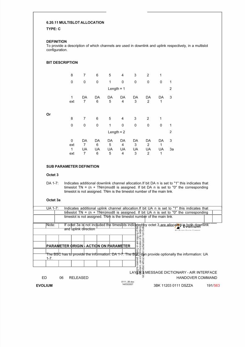
7/11/2019 1. Layer3 Air Interface Messages 0111_06
http://slidepdf.com/reader/full/1-layer3-air-interface-messages-011106 191/562
LAYER 3 MESSAGE DICTIONARY - AIR INTERFACE
ED 06 RELEASED HANDOVER COMMAND
EVOLIUM
0111_06.doc14/03/2007
3BK 11203 0111 DSZZA 191/ 563
6.20.11 MULTISLOT ALLOCATION
TYPE: C
DEFINITIONTo provide a description of which channels are used in downlink and uplink respectively, in a multislotconfiguration.
BIT DESCRIPTION
8 7 6 5 4 3 2 1
0 0 0 1 0 0 0 0 1
Length = 1 2
1ext
DA7
DA6
DA5
DA4
DA3
DA2
DA1
3
Or 8 7 6 5 4 3 2 1
0 0 0 1 0 0 0 0 1
Length = 2 2
0ext
DA7
DA6
DA5
DA4
DA3
DA2
DA1
3
1ext
UA7
UA6
UA5
UA4
UA3
UA2
UA1
3a
SUB PARAMETER DEFINITION
Octet 3
DA 1-7: Indicates additional downlink channel allocation.If bit DA n is set to "1" this indicates thattimeslot TN = (n + TNm)mod8 is assigned. If bit DA n is set to "0" the correspondingtimeslot is not assigned. TNm is the timeslot number of the main link.
Octet 3a
UA 1-7: Indicates additional uplink channel allocation.If bit UA n is set to "1" this indicates that
timeslot TN = (n + TNm)mod8 is assigned. If bit UA n is set to "0" the correspondingtimeslot is not assigned. TNm is the timeslot number of the main link.
Note: If octet 3a is not included the timeslots indicated by octet 3 are allocated in both downlinkand uplink direction
PARAMETER ORIGIN - ACTION ON PARAMETER
The BSC has to provide the information: DA 1-7. The BSC can provide optionally the information: UA1-7.
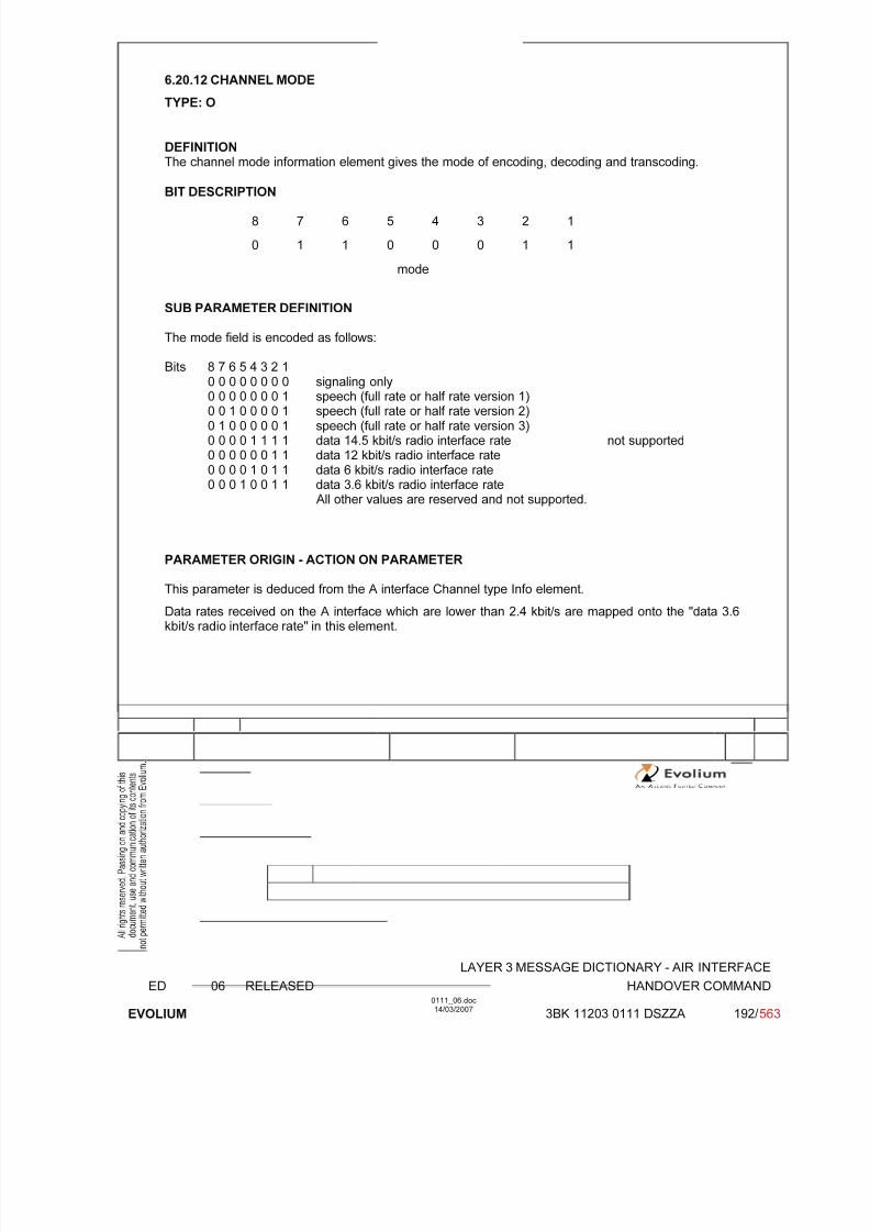
7/11/2019 1. Layer3 Air Interface Messages 0111_06
http://slidepdf.com/reader/full/1-layer3-air-interface-messages-011106 192/562
LAYER 3 MESSAGE DICTIONARY - AIR INTERFACE
ED 06 RELEASED HANDOVER COMMAND
EVOLIUM
0111_06.doc14/03/2007
3BK 11203 0111 DSZZA 192/ 563
6.20.12 CHANNEL MODE
TYPE: O
DEFINITIONThe channel mode information element gives the mode of encoding, decoding and transcoding.
BIT DESCRIPTION
8 7 6 5 4 3 2 1
0 1 1 0 0 0 1 1
mode
SUB PARAMETER DEFINITION
The mode field is encoded as follows:
Bits 8 7 6 5 4 3 2 1
0 0 0 0 0 0 0 0 signaling only0 0 0 0 0 0 0 1 speech (full rate or half rate version 1)0 0 1 0 0 0 0 1 speech (full rate or half rate version 2)0 1 0 0 0 0 0 1 speech (full rate or half rate version 3)0 0 0 0 1 1 1 1 data 14.5 kbit/s radio interface rate not supported0 0 0 0 0 0 1 1 data 12 kbit/s radio interface rate0 0 0 0 1 0 1 1 data 6 kbit/s radio interface rate0 0 0 1 0 0 1 1 data 3.6 kbit/s radio interface rate
All other values are reserved and not supported.
PARAMETER ORIGIN - ACTION ON PARAMETER
This parameter is deduced from the A interface Channel type Info element.
Data rates received on the A interface which are lower than 2.4 kbit/s are mapped onto the "data 3.6kbit/s radio interface rate" in this element.

7/11/2019 1. Layer3 Air Interface Messages 0111_06
http://slidepdf.com/reader/full/1-layer3-air-interface-messages-011106 193/562
LAYER 3 MESSAGE DICTIONARY - AIR INTERFACE
ED 06 RELEASED HANDOVER COMMAND
EVOLIUM
0111_06.doc14/03/2007
3BK 11203 0111 DSZZA 193/ 563
6.20.13 FREQUENCY CHANNEL SEQUENCE
TYPE: C
DEFINITIONTo provide the absolute radio frequency channel numbers used in the Mobile Hopping Sequence. This
parameter will be always used instead of Mobile Allocation, and cell channel description elements(primary band of GSM900).
BIT DESCRIPTION
8 7 6 5 4 3 2 1
1 0 1 1 0 1 0 0 1
2 0 Lowest ARFCN
3 inc skip of ARFCN 1 inc skip of ARFCN 2
: :
10 inc skip of ARFCN 15 inc skip of ARFCN 16
Bit 8 of octet 2 is spare.
SUB PARAMETER DEFINITION
Lowest ARFCN: Value x: 1 to 124this field is coded as the binary representation of the lowest absolute RF channel, appearing in
the sequence of channels used in frequency hopping.
inc skip of ARFCN n:this field is coded as the binary representation of the Increment of preceding absolute RFchannel number appearing in the sequence of channels used in the frequency hopping n =1,...,16.
Range: 0 to 15
The value 0 means a increment of 15, but the concerned channel is not used and the next field (i.e.Increment skip ARFCN N+1) if present must be added to the increment to determine the next absoluteRF channel number.
PARAMETER ORIGIN - ACTION ON PARAMETER
Same as Mobile Allocation and cell channel description. Stored and updated during systemreconfiguration.
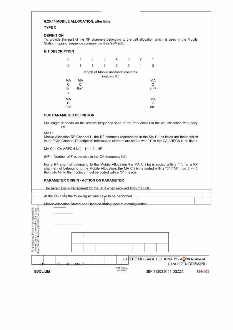
7/11/2019 1. Layer3 Air Interface Messages 0111_06
http://slidepdf.com/reader/full/1-layer3-air-interface-messages-011106 194/562
LAYER 3 MESSAGE DICTIONARY - AIR INTERFACE
ED 06 RELEASED HANDOVER COMMAND
EVOLIUM
0111_06.doc14/03/2007
3BK 11203 0111 DSZZA 194/ 563
6.20.14 MOBILE ALLOCATION, after time
TYPE C
DEFINITION To provide the part of the RF channels belonging to the cell allocation which is used in the MobileStation hopping sequence (primary band in GSM900).
BIT DESCRIPTION
8 7 6 5 4 3 2 1
0 1 1 1 0 0 1 0
length of Mobile allocation contents
(value ≤ 8 )
MAC8n
MAC
8n-1
MAC
8n-7
: :
MAC
008
MAC
001
SUB PARAMETER DEFINITION
MA length depends on the relative frequency span of the frequencies in the cell allocation frequencylist.
MA Ci:Mobile Allocation RF Channel i - the RF channels represented in the MA C i bit fields are those whichin the "Cell Channel Description" information element are coded with "1" in the CA ARFCN N bit fields.
MA Ci = CA ARFCN N(i) i = 1,2...NF
(NF = Number of Frequencies in the CA frequency list).
For a RF channel belonging to the Mobile Allocation the MA C i bit is coded with a "1", for a RFchannel not belonging to the Mobile Allocation, the MA C i bit is coded with a "0".If NF mod 8 <> 0then bits NF to 8n in octet 3 must be coded with a "0" in each.
PARAMETER ORIGIN - ACTION ON PARAMETER
The parameter is transparent for the BTS when received from the BSC.
At the BSC site the following actions have to be performed
Mobile Allocation Stored and Updated during system reconfiguration.
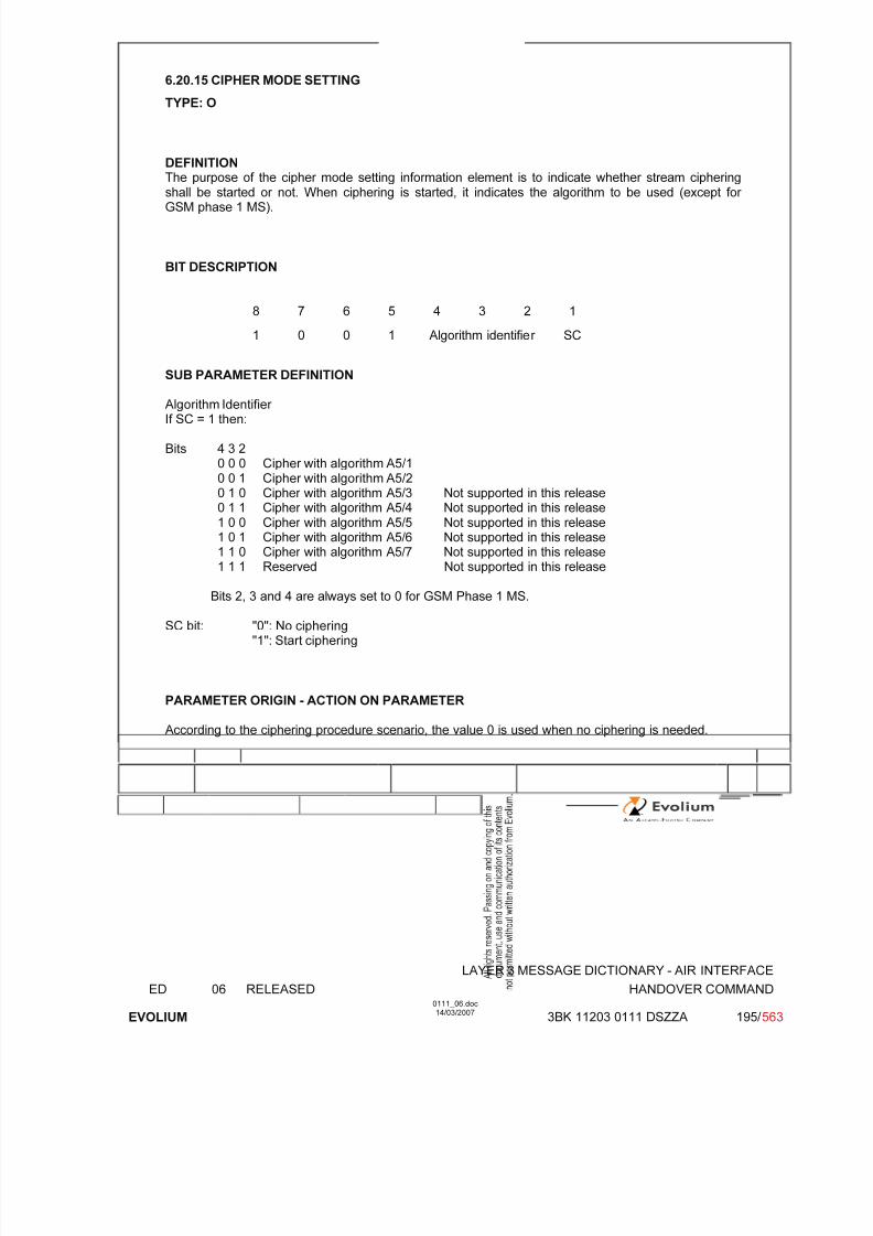
7/11/2019 1. Layer3 Air Interface Messages 0111_06
http://slidepdf.com/reader/full/1-layer3-air-interface-messages-011106 195/562
LAYER 3 MESSAGE DICTIONARY - AIR INTERFACE
ED 06 RELEASED HANDOVER COMMAND
EVOLIUM
0111_06.doc14/03/2007
3BK 11203 0111 DSZZA 195/ 563
6.20.15 CIPHER MODE SETTING
TYPE: O
DEFINITIONThe purpose of the cipher mode setting information element is to indicate whether stream ciphering
shall be started or not. When ciphering is started, it indicates the algorithm to be used (except for GSM phase 1 MS).
BIT DESCRIPTION
8 7 6 5 4 3 2 1
1 0 0 1 Algorithm identifier SC
SUB PARAMETER DEFINITION
Algorithm Identifier If SC = 1 then:
Bits 4 3 20 0 0 Cipher with algorithm A5/10 0 1 Cipher with algorithm A5/20 1 0 Cipher with algorithm A5/3 Not supported in this release0 1 1 Cipher with algorithm A5/4 Not supported in this release1 0 0 Cipher with algorithm A5/5 Not supported in this release1 0 1 Cipher with algorithm A5/6 Not supported in this release1 1 0 Cipher with algorithm A5/7 Not supported in this release
1 1 1 Reserved Not supported in this release
Bits 2, 3 and 4 are always set to 0 for GSM Phase 1 MS.
SC bit: "0": No ciphering"1": Start ciphering
PARAMETER ORIGIN - ACTION ON PARAMETER
According to the ciphering procedure scenario, the value 0 is used when no ciphering is needed.
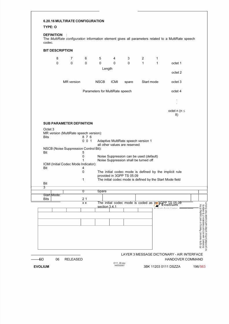
7/11/2019 1. Layer3 Air Interface Messages 0111_06
http://slidepdf.com/reader/full/1-layer3-air-interface-messages-011106 196/562
LAYER 3 MESSAGE DICTIONARY - AIR INTERFACE
ED 06 RELEASED HANDOVER COMMAND
EVOLIUM
0111_06.doc14/03/2007
3BK 11203 0111 DSZZA 196/ 563
6.20.16 MULTIRATE CONFIGURATION
TYPE: O
DEFINITION :The MultiRate configuration information element gives all parameters related to a MultiRate speechcodec.
BIT DESCRIPTION
8 7 6 5 4 3 2 1
0 0 0 0 0 0 1 1 octet 1
Lengthoctet 2
MR version NSCB ICMI spare Start mode octet 3
Parameters for MultiRate speech octet 4
.
.
octet n (n ≤ 8)
SUB PARAMETER DEFINITION
Octet 3MR version (MultiRate speech version):Bits 8 7 6
0 0 1 Adaptive MultiRate speech version 1all other values are reserved
NSCB (Noise Suppression Control Bit):Bit 50 Noise Suppression can be used (default)1 Noise Suppression shall be turned off
ICMI (Initial Codec Mode Indicator):Bit 4
0 The initial codec mode is defined by the implicit ruleprovided in 3GPP TS 05.09
1 The initial codec mode is defined by the Start Mode fieldBit3
0 SpareStart Mode:
Bits 2 1x x The initial codec mode is coded as in 3GPP TS 05.09
section 3.4.1

7/11/2019 1. Layer3 Air Interface Messages 0111_06
http://slidepdf.com/reader/full/1-layer3-air-interface-messages-011106 197/562
LAYER 3 MESSAGE DICTIONARY - AIR INTERFACE
ED 06 RELEASED HANDOVER COMMAND
EVOLIUM
0111_06.doc14/03/2007
3BK 11203 0111 DSZZA 197/ 563
Parameters for MultiRate speech (octet 4 to octet n, n ≤ 8):
1) Parameters for MultiRate speech field for the MR version 1 when a set with one codec mode ischosen
8 7 6 5 4 3 2 1
Set of AMR codec modes octet 4
2) Parameters for MultiRate speech field for the MR version 1 when a set with two codec modes ischosen
8 7 6 5 4 3 2 1
Set of AMR codec modes octet 4
Spare0 0 Threshold 1 octet 5
SpareHysteresis 1 0 0 0 0 octet 6
3) Parameters for MultiRate speech field for the MR version 1 when a set of three codec modes ischosen
8 7 6 5 4 3 2 1
Set of AMR codec modes octet 4
Spare0 0 Threshold 1 octet 5
Hysteresis 1 Threshold 2 octet 6
Threshold Spare2 (cont.) Hysteresis 2 0 0 octet 7
4) Parameters for MultiRate speech field for the MR version 1 when a set of four modes is chosen
8 7 6 5 4 3 2 1
Set of AMR codec modes octet 4
Spare0 0 Threshold 1 octet 5
Hysteresis 1 Threshold 2 octet 6
Threshold Threshold 3
2 (cont.) Hysteresis 2 octet 7
Threshold (3) Hysteresis 3 octet 8
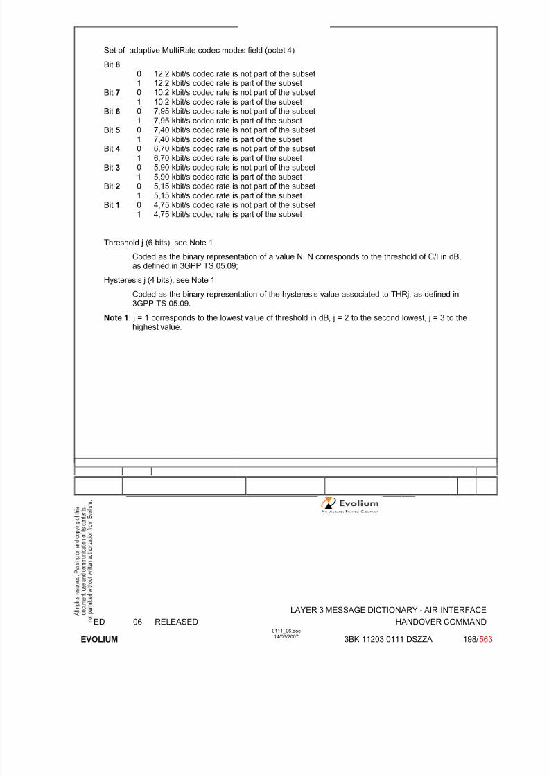
7/11/2019 1. Layer3 Air Interface Messages 0111_06
http://slidepdf.com/reader/full/1-layer3-air-interface-messages-011106 198/562
LAYER 3 MESSAGE DICTIONARY - AIR INTERFACE
ED 06 RELEASED HANDOVER COMMAND
EVOLIUM
0111_06.doc14/03/2007
3BK 11203 0111 DSZZA 198/ 563
Set of adaptive MultiRate codec modes field (octet 4)
Bit 8 0 12,2 kbit/s codec rate is not part of the subset1 12,2 kbit/s codec rate is part of the subset
Bit 7 0 10,2 kbit/s codec rate is not part of the subset1 10,2 kbit/s codec rate is part of the subset
Bit 6 0 7,95 kbit/s codec rate is not part of the subset
1 7,95 kbit/s codec rate is part of the subsetBit 5 0 7,40 kbit/s codec rate is not part of the subset
1 7,40 kbit/s codec rate is part of the subsetBit 4 0 6,70 kbit/s codec rate is not part of the subset
1 6,70 kbit/s codec rate is part of the subset
Bit 3 0 5,90 kbit/s codec rate is not part of the subset1 5,90 kbit/s codec rate is part of the subset
Bit 2 0 5,15 kbit/s codec rate is not part of the subset1 5,15 kbit/s codec rate is part of the subset
Bit 1 0 4,75 kbit/s codec rate is not part of the subset1 4,75 kbit/s codec rate is part of the subset
Threshold j (6 bits), see Note 1
Coded as the binary representation of a value N. N corresponds to the threshold of C/I in dB,as defined in 3GPP TS 05.09;
Hysteresis j (4 bits), see Note 1
Coded as the binary representation of the hysteresis value associated to THRj, as defined in3GPP TS 05.09.
Note 1: j = 1 corresponds to the lowest value of threshold in dB, j = 2 to the second lowest, j = 3 to thehighest value.

7/11/2019 1. Layer3 Air Interface Messages 0111_06
http://slidepdf.com/reader/full/1-layer3-air-interface-messages-011106 199/562
LAYER 3 MESSAGE DICTIONARY - AIR INTERFACE
ED 06 RELEASED HANDOVER COMPLETE
EVOLIUM
0111_06.doc14/03/2007
3BK 11203 0111 DSZZA 199/ 563
6.21 HANDOVER COMPLETE
NAME HANDOVER COMPLETE
INTERFACE RADIO ABIS A
CHANNEL/ USAGE
SDCCH/FACCH BTS Transparent
3GPP-REF 44.018
FUNCTION This message is sent on the main DCCH from Mobile Station to the network toindicate that the Mobile Station has established the main signalling linksuccessfully.
DIRECTION From: MS To: BSC
INFORMATION ELEMENT NAME TYPE COMMENT LENGTH(byte)
INFORMATIONELEMENT
LISTHeader RR CauseMobile Observed Time Difference
M V O TLV not used
215
IMPLEMENTATION MAXIMUM LENGTH 3
NORMAL SITUATION ABNORMAL SITUATION TIMER
FOLLOWING
EVENT Release of old channels Handover failure
T3013
T9013
SPECIFDOC. REF.
Internal Channel Changes (ref. [6])External Channel Changes (ref. [7])

7/11/2019 1. Layer3 Air Interface Messages 0111_06
http://slidepdf.com/reader/full/1-layer3-air-interface-messages-011106 200/562
LAYER 3 MESSAGE DICTIONARY - AIR INTERFACE
ED 06 RELEASED HANDOVER COMPLETE
EVOLIUM
0111_06.doc14/03/2007
3BK 11203 0111 DSZZA 200/ 563
6.21.1 GENERAL DESCRIPTION
8 7 6 5 4 3 2 1
0 0 0 0 0 1 1 0
0 0 1 0 1 1 0 0
RR Cause RR CAUSE VALUE
6.21.2 RR CAUSE
TYPE: M
DEFINITIONTo provide the reason for handover complete.
BIT DESCRIPTION
8 7 6 5 4 3 2 1
RR CAUSE VALUE
SUB PARAMETER DEFINITION
RR cause value (octet 1)
PARAMETER ORIGIN - ACTION ON PARAMETER
This parameter is transparent for the BTS.
The BSC does not check the value given by the MS. The BSC gives this information to the MSC in the"Handover Complete" message on the A Interface.
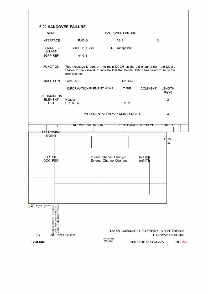
7/11/2019 1. Layer3 Air Interface Messages 0111_06
http://slidepdf.com/reader/full/1-layer3-air-interface-messages-011106 201/562
LAYER 3 MESSAGE DICTIONARY - AIR INTERFACE
ED 06 RELEASED HANDOVER FAILURE
EVOLIUM
0111_06.doc14/03/2007
3BK 11203 0111 DSZZA 201/ 563
6.22 HANDOVER FAILURE
NAME HANDOVER FAILURE
INTERFACE RADIO ABIS A
CHANNEL/ USAGE
SDCCH/FACCH BTS Transparent
3GPP-REF 44.018
FUNCTION This message is sent on the main DCCH on the old channel from the MobileStation to the network to indicate that the Mobile Station has failed to seize thenew channel.
DIRECTION From: MS To: BSC
INFORMATION ELEMENT NAME TYPE COMMENT LENGTH(byte)
INFORMATIONELEMENT
LISTHeader RR Cause M V
21
IMPLEMENTATION MAXIMUM LENGTH 3
NORMAL SITUATION ABNORMAL SITUATION TIMER
FOLLOWING
EVENTT3103
T8
SPECIFDOC. REF.
Internal Channel Changes (ref. [6])External Channel Changes (ref. [7])
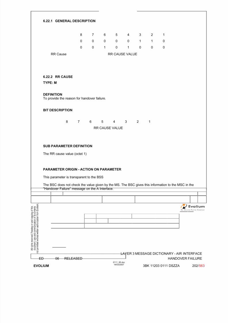
7/11/2019 1. Layer3 Air Interface Messages 0111_06
http://slidepdf.com/reader/full/1-layer3-air-interface-messages-011106 202/562
LAYER 3 MESSAGE DICTIONARY - AIR INTERFACE
ED 06 RELEASED HANDOVER FAILURE
EVOLIUM
0111_06.doc14/03/2007
3BK 11203 0111 DSZZA 202/ 563
6.22.1 GENERAL DESCRIPTION
8 7 6 5 4 3 2 1
0 0 0 0 0 1 1 0
0 0 1 0 1 0 0 0
RR Cause RR CAUSE VALUE
6.22.2 RR CAUSE
TYPE: M
DEFINITION
To provide the reason for handover failure.
BIT DESCRIPTION
8 7 6 5 4 3 2 1
RR CAUSE VALUE
SUB PARAMETER DEFINITION
The RR cause value (octet 1)
PARAMETER ORIGIN - ACTION ON PARAMETER
This parameter is transparent to the BSS
The BSC does not check the value given by the MS. The BSC gives this information to the MSC in the"Handover Failure" message on the A Interface.

7/11/2019 1. Layer3 Air Interface Messages 0111_06
http://slidepdf.com/reader/full/1-layer3-air-interface-messages-011106 203/562
LAYER 3 MESSAGE DICTIONARY - AIR INTERFACE
ED 06 RELEASED IMMEDIATE ASSIGNMENT
EVOLIUM
0111_06.doc14/03/2007
3BK 11203 0111 DSZZA 203/ 563
6.23 IMMEDIATE ASSIGNMENT
NAME IMMEDIATE ASSIGNMENT
INTERFACE RADIO ABIS A
CHANNEL/ USAGE
CCCH/(AGCH-PCH)
3GPP-REF 44.018
FUNCTION This message is sent on the CCCH by the network to the MS in idle mode tochange the channel configuration to dedicated configuration while staying in thesame cell or to allocate resources for uplink or downlink packet data transfer.
DIRECTION From: BTS To: MS
INFORMATION ELEMENT NAME TYPE COMMENT LENGTH(byte)
INFORMATIONELEMENT
LISTL2 Pseudo LengthHeader Page modeDedicated mode or TBFChannel DescriptionPacket Channel DescriptionRequest ReferenceTiming AdvanceMobile AllocationStarting Time
IA Rest Octets
M V M V M V M V C V C V M V M V M LV O TV
M V
Not Used
12½½3331
1-93
0-11
IMPLEMENTATION MAXIMUM LENGTH 23
NORMAL SITUATION ABNORMAL SITUATION TIMER
FOLLOWINGEVENT
Access to main DCCHor completion of establishment of Temporary Block Flow for data
transfer
Release resources if MS doesnot access the new channelor retries establishment of downlink TBF
T3101 (for CS service
only)
SPECIFDOC. REF.
Paging and Access Grant Control (ref. [1])Radio and link establishment (ref. [2])FBS GPRS - Radio Interface - RRM sublayer - PCC (ref. [29])
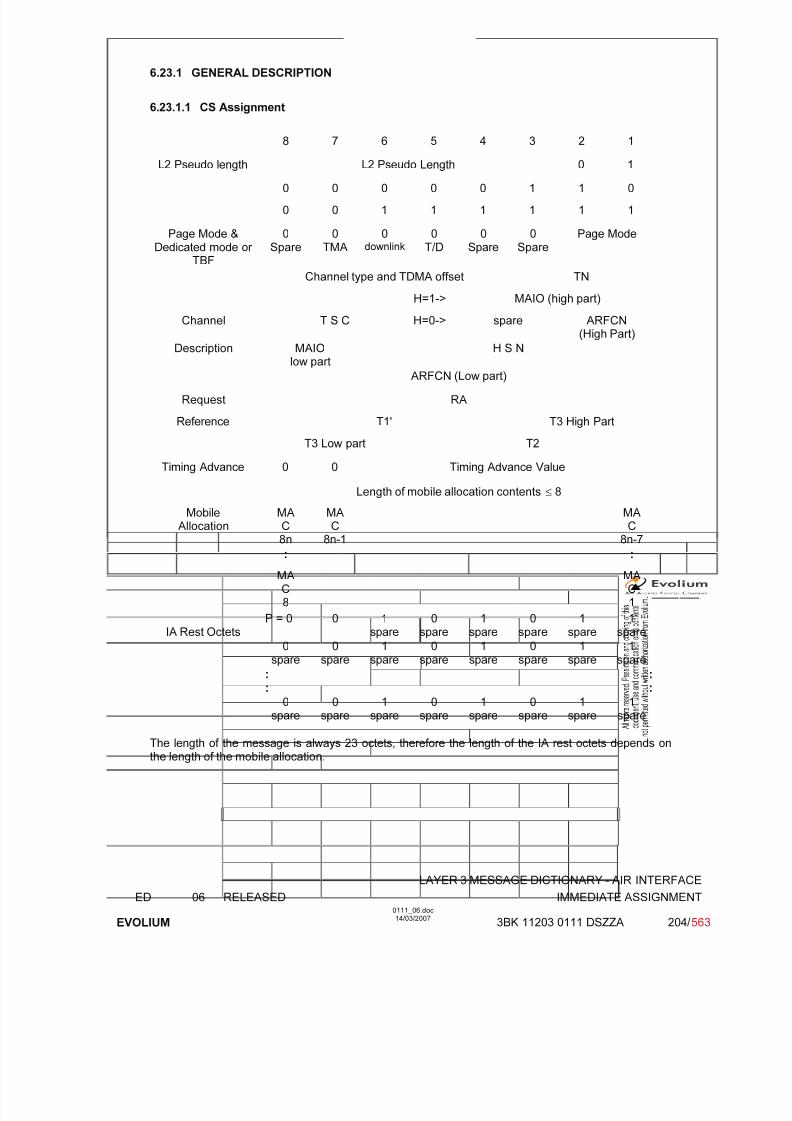
7/11/2019 1. Layer3 Air Interface Messages 0111_06
http://slidepdf.com/reader/full/1-layer3-air-interface-messages-011106 204/562
LAYER 3 MESSAGE DICTIONARY - AIR INTERFACE
ED 06 RELEASED IMMEDIATE ASSIGNMENT
EVOLIUM
0111_06.doc14/03/2007
3BK 11203 0111 DSZZA 204/ 563
6.23.1 GENERAL DESCRIPTION
6.23.1.1 CS Assignment
8 7 6 5 4 3 2 1
L2 Pseudo length L2 Pseudo Length 0 1
0 0 0 0 0 1 1 0
0 0 1 1 1 1 1 1
Page Mode &Dedicated mode or
TBF
0Spare
0TMA
0downlink
0T/D
0Spare
0Spare
Page Mode
Channel type and TDMA offset TN
H=1-> MAIO (high part)
Channel T S C H=0-> spare ARFCN(High Part)
Description MAIOlow part
H S N
ARFCN (Low part)
Request RA
Reference T1' T3 High Part
T3 Low part T2
Timing Advance 0 0 Timing Advance Value
Length of mobile allocation contents ≤ 8
MobileAllocation MAC8n
MAC8n-1
MAC8n-7
: :
MAC8
MAC1
IA Rest OctetsP = 0 0 1
spare0
spare1
spare0
spare1
spare1
spare
0spare
0spare
1spare
0spare
1spare
0spare
1spare
1spare
:
:
:
:0
spare0
spare1
spare0
spare1
spare0
spare1
spare1
spare
The length of the message is always 23 octets, therefore the length of the IA rest octets depends onthe length of the mobile allocation.

7/11/2019 1. Layer3 Air Interface Messages 0111_06
http://slidepdf.com/reader/full/1-layer3-air-interface-messages-011106 205/562
LAYER 3 MESSAGE DICTIONARY - AIR INTERFACE
ED 06 RELEASED IMMEDIATE ASSIGNMENT
EVOLIUM
0111_06.doc14/03/2007
3BK 11203 0111 DSZZA 205/ 563
6.23.1.2 PS assignment
8 7 6 5 4 3 2 1
L2 Pseudo length L2 Pseudo Length 0 1
0 0 0 0 0 1 1 0
0 0 1 1 1 1 1 1
Page Mode &Dedicated mode or
TBF
0Spare
0TMA
downlink 1T/D
0Spare
0Spare
Page Mode
Packet Channel Field dedicated to the GPRS service
Description See FBS GPRS - Radio Interface - RRM sublayer - PCC (ref. [31])
Request RA
Reference T1' T3 High Part
T3 Low part T2
Timing Advance 0 0 Timing Advance Value
Length of mobile allocation contents ≤<= 8
MobileAllocation
MAC8n
MAC
8n-1
MAC
8n-7
: :
MAC8
MAC1
IA Rest Octets See FBS GPRS - Radio Interface - RRM sublayer - PCC (ref. [29])

7/11/2019 1. Layer3 Air Interface Messages 0111_06
http://slidepdf.com/reader/full/1-layer3-air-interface-messages-011106 206/562
LAYER 3 MESSAGE DICTIONARY - AIR INTERFACE
ED 06 RELEASED IMMEDIATE ASSIGNMENT
EVOLIUM
0111_06.doc14/03/2007
3BK 11203 0111 DSZZA 206/ 563
6.23.2 L2 PSEUDO LENGTH
TYPE: M
DEFINITIONThis information element indicates the number of octets following it in the message which are to beinterpreted in the scope of phase 1 protocol.
BIT DESCRIPTION
8 7 6 5 4 3 2 1
L2 Pseudo Length value 0 1
PARAMETER ORIGIN - ACTION ON PARAMETER

7/11/2019 1. Layer3 Air Interface Messages 0111_06
http://slidepdf.com/reader/full/1-layer3-air-interface-messages-011106 207/562
LAYER 3 MESSAGE DICTIONARY - AIR INTERFACE
ED 06 RELEASED IMMEDIATE ASSIGNMENT
EVOLIUM
0111_06.doc14/03/2007
3BK 11203 0111 DSZZA 207/ 563
6.23.3 PAGE MODE / Dedicated mode or TBF
TYPE: M
DEFINITION
• Page Mode
To control the action of the Mobile Station belonging to the paging subgroup corresponding tothe paging subchannel.
• Dedicated mode or TBF
Indicates to the mobile station whether the rest of the message shall be decoded as anIMMEDIATE ASSIGNMENT message allocating a channel in dedicated mode or whether therest of the message shall be decoded as the allocation of a Temporary Block Flow.
This IE also indicates:
◊ whether the IMMEDIATE ASSIGNMENT message relates to a downlink TBF for a mobilestation in packet idle mode; and
◊ whether the IMMEDIATE ASSIGNMENT message is the first message of two IMMEDIATEASSIGNMENT messages in a two-message assignment of an uplink or downlink TBF
BIT DESCRIPTION
8 7 6 5 4 3 2 1
0spare
0TMA
downlink T/D 0spare
0spare
Page Mode
|____________________________| |_______________________|Dedicated mode or TBF Page Mode
SUB PARAMETER DEFINITION
Page Mode 0 0 Normal paging used for PS assignments0 1 Extended paging Not used1 0 Paging - Reorganisation Not used1 1 Same as before used for CS assignments
TMA (Two Message Assignment)0 No meaning Note that TMA is always set to ‘0’ by
the Alcatel BSS1 This message is the first message of two in a
two-message assignment of an uplink or downlink TBF
not used by the Alcatel BSS
downlink (downlink assignment to mobile in packet idle mode)0 No meaning1 This message assigns a resource to the mobile station
identified in the IA rest octet.The type of resource (either dedicated mode or TBF) isindicated by T/D bit.
T/D (TBF or Dedicated mode):0 : this message assigns a dedicated mode resource1 : this message assigns a Temporary Block Flow (TBF)

7/11/2019 1. Layer3 Air Interface Messages 0111_06
http://slidepdf.com/reader/full/1-layer3-air-interface-messages-011106 208/562
LAYER 3 MESSAGE DICTIONARY - AIR INTERFACE
ED 06 RELEASED IMMEDIATE ASSIGNMENT
EVOLIUM
0111_06.doc14/03/2007
3BK 11203 0111 DSZZA 208/ 563
PARAMETER ORIGIN - ACTION ON PARAMETER

7/11/2019 1. Layer3 Air Interface Messages 0111_06
http://slidepdf.com/reader/full/1-layer3-air-interface-messages-011106 209/562
LAYER 3 MESSAGE DICTIONARY - AIR INTERFACE
ED 06 RELEASED IMMEDIATE ASSIGNMENT
EVOLIUM
0111_06.doc14/03/2007
3BK 11203 0111 DSZZA 209/ 563
6.23.4 CHANNEL DESCRIPTION
TYPE: C
DEFINITION
To provide a description of an allocatable channel together with its SACCH.
BIT DESCRIPTION
8 7 6 5 4 3 2 1
Channel type and TDMA offset TN 1
TSCH=1-> MAIO (high part) 2
H=0-> spare ARFCN (Hpart)
MAIO low part H S N 3
A R F C N (low part)
SUB PARAMETER DEFINITION
Octet 1
Channel type and TDMA offset.
Bits 8 7 6 5 40 0 0 0 1 TCH/F + ACCHs0 0 0 1 T TCH/H + ACCHs
0 0 1 T T SDCCH/4 + SACCH/C4 or CBCH (SDCCH/4)0 1 T T T SDCCH/8 + SACCH/C8 or CBCH (SDCCH/8)all other values are reserved.
T bit indicates the Subchannel Number.
TN : Time slot (0 to 7)
Octets 2 and 3:
TSC : Training Sequence Code (0 to 7)
H : "0" Single RF channel
"1" RF hopping channel
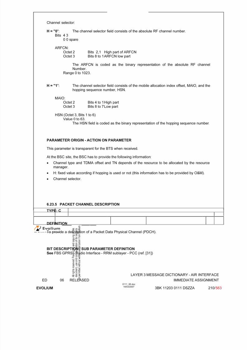
7/11/2019 1. Layer3 Air Interface Messages 0111_06
http://slidepdf.com/reader/full/1-layer3-air-interface-messages-011106 210/562
LAYER 3 MESSAGE DICTIONARY - AIR INTERFACE
ED 06 RELEASED IMMEDIATE ASSIGNMENT
EVOLIUM
0111_06.doc14/03/2007
3BK 11203 0111 DSZZA 210/ 563
Channel selector:
H = "0": The channel selector field consists of the absolute RF channel number.Bits 4 3
0 0 spare
ARFCN:
Octet 2 Bits 2,1 High part of ARFCNOctet 3 Bits 8 to 1 ARFCN low part
The ARFCN is coded as the binary representation of the absolute RF channelNumber.
Range 0 to 1023.
H = "1": The channel selector field consists of the mobile allocation index offset, MAIO, and thehopping sequence number, HSN.
MAIO:Octet 2 Bits 4 to 1 High part
Octet 3 Bits 8 to 7 Low part
HSN (Octet 3, Bits 1 to 6)Value 0 to 63.
The HSN field is coded as the binary representation of the hopping sequence number.
PARAMETER ORIGIN - ACTION ON PARAMETER
This parameter is transparent for the BTS when received.
At the BSC site, the BSC has to provide the following information:
• Channel type and TDMA offset and TN depends of the resource to be allocated by the resourcemanager.
• H: fixed value according if hopping is used or not (this information has to be provided by O&M).
• Channel selector.
6.23.5 PACKET CHANNEL DESCRIPTION
TYPE: C
DEFINITION
To provide a description of a Packet Data Physical Channel (PDCH).
BIT DESCRIPTION / SUB PARAMETER DEFINITIONSee FBS GPRS - Radio Interface - RRM sublayer - PCC (ref. [31])
7/11/2019 1. Layer3 Air Interface Messages 0111_06
http://slidepdf.com/reader/full/1-layer3-air-interface-messages-011106 211/562
LAYER 3 MESSAGE DICTIONARY - AIR INTERFACE
ED 06 RELEASED IMMEDIATE ASSIGNMENT
EVOLIUM
0111_06.doc14/03/2007
3BK 11203 0111 DSZZA 211/ 563
PARAMETER ORIGIN - ACTION ON PARAMETER
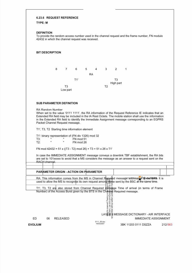
7/11/2019 1. Layer3 Air Interface Messages 0111_06
http://slidepdf.com/reader/full/1-layer3-air-interface-messages-011106 212/562
LAYER 3 MESSAGE DICTIONARY - AIR INTERFACE
ED 06 RELEASED IMMEDIATE ASSIGNMENT
EVOLIUM
0111_06.doc14/03/2007
3BK 11203 0111 DSZZA 212/ 563
6.23.6 REQUEST REFERENCE
TYPE: M
DEFINITIONTo provide the random access number used in the channel request and the frame number, FN modulo42432 in which the channel request was received.
BIT DESCRIPTION
8 7 6 5 4 3 2 1
RA
T1' T3
High partT3
Low partT2
SUB PARAMETER DEFINITION
RA Random Number When set to the value ‘0111 1111’, the RA information of the Request Reference IE indicates that anExtended RA field may be included in the IA Rest Octets. The mobile station shall use the informationin the Extended RA field to identify the Immediate Assignment message corresponding to an EGPRSPacket Channel Request message.
T1', T3, T2 Starting time information element
T1': binary representation of (FN div 1326) mod 32T3: " " FN mod 51T2: " " FN mod 26
FN mod 42432 = 51 x ((T3 - T2) mod 26) + T3 + 51 x 26 x T1'
In case the IMMEDIATE ASSIGNMENT message conveys a downlink TBF establishment, the RA bitsare set to 101xxxxx to avoid that a MS considers the message as an answer to a request sent on theRACH channel.
PARAMETER ORIGIN - ACTION ON PARAMETER
RA: This information comes from the MS in Channel Required message addressed by the BTS. It isused to allow the MS to recognise its own request among those sent by the BSC at the same time.
T1', T3, T2 are also stored from Channel Required message Time of arrival (in terms of FrameNumber) of the Access Burst given by the BTS in the Channel Required message.
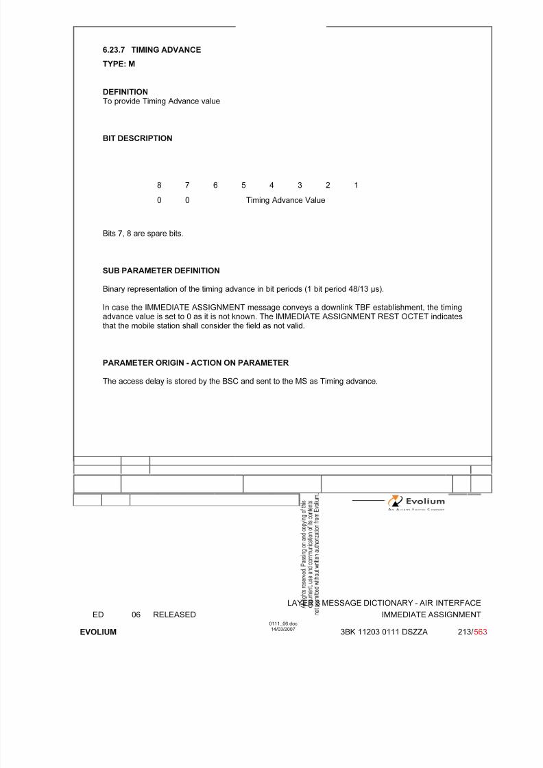
7/11/2019 1. Layer3 Air Interface Messages 0111_06
http://slidepdf.com/reader/full/1-layer3-air-interface-messages-011106 213/562
LAYER 3 MESSAGE DICTIONARY - AIR INTERFACE
ED 06 RELEASED IMMEDIATE ASSIGNMENT
EVOLIUM
0111_06.doc14/03/2007
3BK 11203 0111 DSZZA 213/ 563
6.23.7 TIMING ADVANCE
TYPE: M
DEFINITIONTo provide Timing Advance value
BIT DESCRIPTION
8 7 6 5 4 3 2 1
0 0 Timing Advance Value
Bits 7, 8 are spare bits.
SUB PARAMETER DEFINITION
Binary representation of the timing advance in bit periods (1 bit period 48/13 s).
In case the IMMEDIATE ASSIGNMENT message conveys a downlink TBF establishment, the timingadvance value is set to 0 as it is not known. The IMMEDIATE ASSIGNMENT REST OCTET indicatesthat the mobile station shall consider the field as not valid.
PARAMETER ORIGIN - ACTION ON PARAMETER
The access delay is stored by the BSC and sent to the MS as Timing advance.

7/11/2019 1. Layer3 Air Interface Messages 0111_06
http://slidepdf.com/reader/full/1-layer3-air-interface-messages-011106 214/562
LAYER 3 MESSAGE DICTIONARY - AIR INTERFACE
ED 06 RELEASED IMMEDIATE ASSIGNMENT
EVOLIUM
0111_06.doc14/03/2007
3BK 11203 0111 DSZZA 214/ 563
6.23.8 MOBILE ALLOCATION
TYPE: M
DEFINITIONTo provide the part of the RF channels belonging to the cell allocation which is used in the MobileStation hopping sequence.
BIT DESCRIPTION
8 7 6 5 4 3 2 1
Length of Mobile alloc. contents ≤ 8
MAC8n
MAC
8n-1
MAC
8n-7
:
MA
C8
MA
C1
SUB PARAMETER DEFINITION
MA length depends on the relative frequency span of the frequencies in the cell allocation frequencylist
MA Ci: Mobile Allocation RF channel i - the RF channels represented in the MA Ci bit fields are those which in the cell channel description information element are coded with "1" in the CA ARFCNN bit fields.
MA Ci = CA ARFCN N(i) i = 1,2...NF
(NF = Number of Frequencies in the CA frequency list).
For a RF channel belonging to the Mobile Allocation the MA Ci bit is coded with a "1",for a RF channel not belonging to the Mobile Allocation, the MA Ci bit is coded with a "0".
PARAMETER ORIGIN - ACTION ON PARAMETER
The parameter is transparent for the BTS when received from the BSC.
Note: mandatory if Frequency Hopping system in used, otherwise if not sent the length is 0
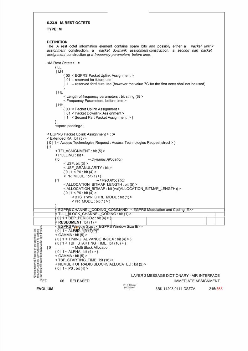
7/11/2019 1. Layer3 Air Interface Messages 0111_06
http://slidepdf.com/reader/full/1-layer3-air-interface-messages-011106 215/562
LAYER 3 MESSAGE DICTIONARY - AIR INTERFACE
ED 06 RELEASED IMMEDIATE ASSIGNMENT
EVOLIUM
0111_06.doc14/03/2007
3BK 11203 0111 DSZZA 215/ 563
6.23.9 IA REST OCTETS
TYPE: M
DEFINITIONThe IA rest octet information element contains spare bits and possibly either a packet uplink assignment construction, a packet downlink assignment construction, a second part packet
assignment construction or a frequency parameters, before time.
<IA Rest Octets> ::={ LL| LH
{ 00 < EGPRS Packet Uplink Assignment >| 01 -- reserved for future use| 1 -- reserved for future use (however the value 7C for the first octet shall not be used)}
| HL< Length of frequency parameters : bit string (6) >< Frequency Parameters, before time >
| HH
{ 00 < Packet Uplink Assignment >| 01 < Packet Downlink Assignment >| 1 < Second Part Packet Assignment > }
}<spare padding> ;
< EGPRS Packet Uplink Assignment > : :=< Extended RA : bit (5) >{ 0 | 1 < Access Technologies Request : Access Technologies Request struct > }{ 1
< TFI_ASSIGNMENT : bit (5) >< POLLING : bit >{ 0 -- Dynamic Allocation
< USF: bit (3) >< USF_GRANULARITY : bit >{ 0 | 1 < P0 : bit (4) >< PR_MODE : bit (1) >}
| 1 -- Fixed Allocation < ALLOCATION_BITMAP_LENGTH : bit (5) >< ALLOCATION_BITMAP : bit (val(ALLOCATION_BITMAP_LENGTH)) >{ 0 | 1 < P0 : bit (4) >
< BTS_PWR_CTRL_MODE : bit (1) >< PR_MODE : bit (1) > }
}< EGPRS CHANNEL_CODING_COMMAND : < EGPRS Modulation and Coding IE>>< TLLI_BLOCK_CHANNEL_CODING : bit (1) >{ 0 | 1 < BEP_PERIOD2 : bit (4) > }< RESEGMENT : bit (1) >< EGPRS Window Size : < EGPRS Window Size IE>>{ 0 | 1 < ALPHA : bit (4) >}< GAMMA : bit (5) >{ 0 | 1 < TIMING_ADVANCE_INDEX : bit (4) > }{ 0 | 1 < TBF_STARTING_TIME : bit (16) > }
| 0 -- Multi Block Allocation{ 0 | 1 < ALPHA : bit (4) > }< GAMMA : bit (5) >< TBF_STARTING_TIME : bit (16) >< NUMBER OF RADIO BLOCKS ALLOCATED : bit (2) >
{ 0 | 1 < P0 : bit (4) >

7/11/2019 1. Layer3 Air Interface Messages 0111_06
http://slidepdf.com/reader/full/1-layer3-air-interface-messages-011106 216/562
LAYER 3 MESSAGE DICTIONARY - AIR INTERFACE
ED 06 RELEASED IMMEDIATE ASSIGNMENT
EVOLIUM
0111_06.doc14/03/2007
3BK 11203 0111 DSZZA 216/ 563
< BTS_PWR_CTRL_MODE : bit (1) >< PR_MODE : bit (1) > }
} ;
<Access Technologies Request struct> ::= -- recursive structure allows any combination of Accesstechnologies
<Access Technology Type : bit (4)>
{ 0 | 1 <Access Technologies Request struct> } ;
< Packet Uplink Assignment > ::=
{ 1< TFI_ASSIGNMENT : bit (5) >< POLLING : bit >{ 0
-- Dynamic Allocation < USF: bit (3) >< USF_GRANULARITY : bit >{ 0 | 1 < P0 : bit (4) >< PR_MODE : bit (1) > }
| 1 -- Fixed Allocation < ALLOCATION_BITMAP_LENGTH : bit (5) >< ALLOCATION_BITMAP : bit (val(ALLOCATION_BITMAP_LENGTH)) >{ 0 | 1 < P0 : bit (4) >
< BTS_PWR_CTRL_MODE : bit (1) >< PR_MODE : bit (1) > }
}< CHANNEL_CODING_COMMAND : bit (2) >< TLLI_BLOCK_CHANNEL_CODING : bit >
{ 0 | 1 < ALPHA : bit (4) > }< GAMMA : bit (5) >{ 0 | 1 < TIMING_ADVANCE_INDEX : bit (4) > }
{ 0 | 1 < TBF_STARTING_TIME : bit (16) > }| 0-- Single Block Allocation
{ 0 | 1 < ALPHA : bit (4) >}< GAMMA : bit (5) >0 1 --
See Note 1< TBF_STARTING_TIME : bit (16) >{ L | H < P0 : bit (4) >
< BTS_PWR_CTRL_MODE : bit (1) >< PR_MODE : bit (1) >}
}{ null | L --
Receiver compatible with earlier release | H-- Additions for R99
{ 0 | 1 < Extended RA : bit (5) > }} ;
< Packet Downlink Assignment > ::=< TLLI : bit (32) >{ 0 | 1
< TFI_ASSIGNMENT : bit (5) >< RLC_MODE : bit >{ 0 | 1 < ALPHA : bit (4) > }< GAMMA : bit (5) >
< POLLING : bit >

7/11/2019 1. Layer3 Air Interface Messages 0111_06
http://slidepdf.com/reader/full/1-layer3-air-interface-messages-011106 217/562
LAYER 3 MESSAGE DICTIONARY - AIR INTERFACE
ED 06 RELEASED IMMEDIATE ASSIGNMENT
EVOLIUM
0111_06.doc14/03/2007
3BK 11203 0111 DSZZA 217/ 563
< TA_VALID : bit (1) > }{ 0 | 1 < TIMING_ADVANCE_INDEX : bit (4) > }{ 0 | 1 < TBF_STARTING_TIME : bit (16) > }{ 0 | 1 < P0 : bit (4) >
< BTS_PWR_CRTL_MODE : bit (1) >< PR_MODE : bit (1) > }
{ null | L --
Receiver compatible with earlier release | H-- Additions for R99
-- indicates EGPRS TBF mode, see 44.060 < EGPRS Window Size : < EGPRS Window Size IE >>< LINK_QUALITY_MEASUREMENT_MODE : bit (2) >{ 0 | 1 < BEP_PERIOD2 : bit (4) > }
} ;
< Frequency Parameters, before time > ::={ null-- Length of frequency parameters = 0
| 0 0< MAIO : bit (6) >< Mobile Allocation : octet (val (Length of frequency parameters) – 1) >
} ;
< Second Part Packet Assignment > ::={ null | L --
Receiver compatible with earlier release | H-- Additions for R99
{ 0 | 1 < Extended RA : bit (5) > }}
BIT DESCRIPTION
See FBS GPRS - Radio Interface - RRM sublayer - PCC (ref. [31]).
PARAMETER ORIGIN - ACTION ON PARAMETER
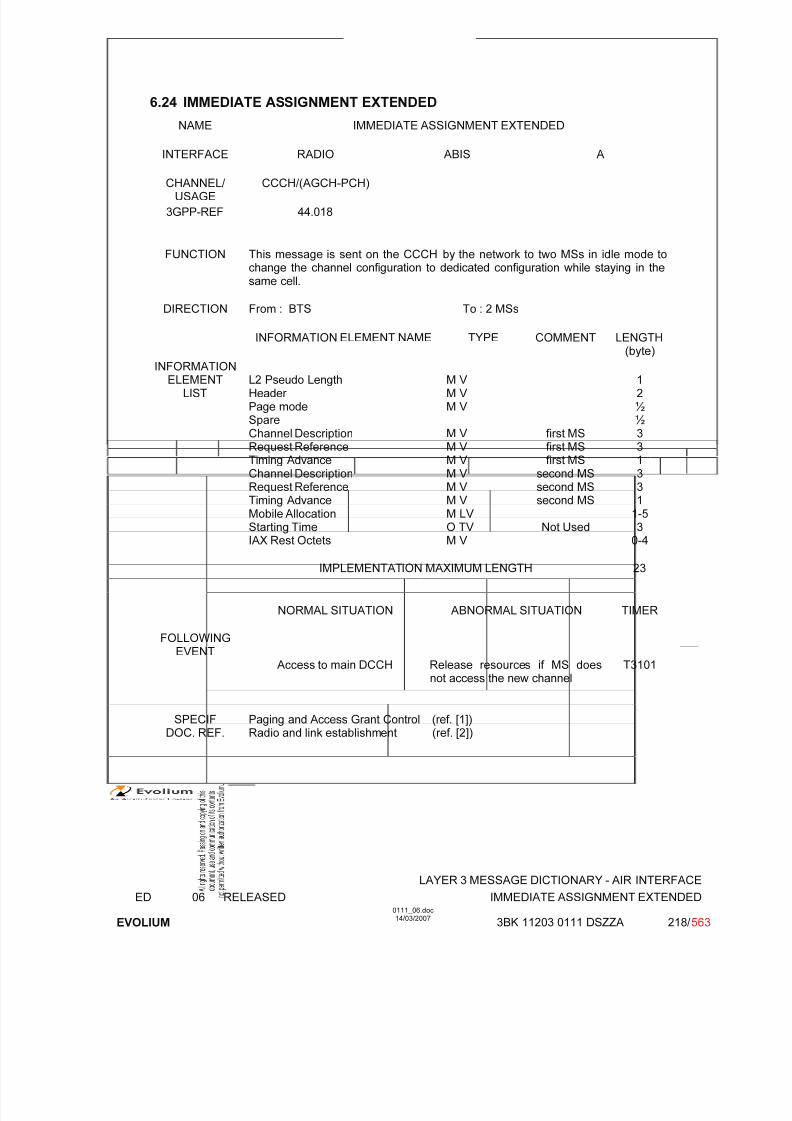
7/11/2019 1. Layer3 Air Interface Messages 0111_06
http://slidepdf.com/reader/full/1-layer3-air-interface-messages-011106 218/562
LAYER 3 MESSAGE DICTIONARY - AIR INTERFACE
ED 06 RELEASED IMMEDIATE ASSIGNMENT EXTENDED
EVOLIUM
0111_06.doc14/03/2007
3BK 11203 0111 DSZZA 218/ 563
6.24 IMMEDIATE ASSIGNMENT EXTENDED
NAME IMMEDIATE ASSIGNMENT EXTENDED
INTERFACE RADIO ABIS A
CHANNEL/ USAGE
CCCH/(AGCH-PCH)
3GPP-REF 44.018
FUNCTION This message is sent on the CCCH by the network to two MSs in idle mode tochange the channel configuration to dedicated configuration while staying in thesame cell.
DIRECTION From : BTS To : 2 MSs
INFORMATION ELEMENT NAME TYPE COMMENT LENGTH(byte)
INFORMATIONELEMENT
LISTL2 Pseudo LengthHeader Page modeSpareChannel DescriptionRequest ReferenceTiming AdvanceChannel DescriptionRequest ReferenceTiming Advance
Mobile AllocationStarting TimeIAX Rest Octets
M V M V M V
M V M V M V M V M V M V
M LV O TV M V
first MSfirst MSfirst MS
second MSsecond MSsecond MS
Not Used
12½½331331
1-530-4
IMPLEMENTATION MAXIMUM LENGTH 23
NORMAL SITUATION ABNORMAL SITUATION TIMER
FOLLOWINGEVENT
Access to main DCCH Release resources if MS doesnot access the new channel
T3101
SPECIFDOC. REF.
Paging and Access Grant Control (ref. [1])Radio and link establishment (ref. [2])

7/11/2019 1. Layer3 Air Interface Messages 0111_06
http://slidepdf.com/reader/full/1-layer3-air-interface-messages-011106 219/562
LAYER 3 MESSAGE DICTIONARY - AIR INTERFACE
ED 06 RELEASED IMMEDIATE ASSIGNMENT EXTENDED
EVOLIUM
0111_06.doc14/03/2007
3BK 11203 0111 DSZZA 219/ 563
6.24.1 GENERAL DESCRIPTION
8 7 6 5 4 3 2 1
L2 Pseudo length L2 Pseudo Length 0 1
0 0 0 0 0 1 1 0
0 0 1 1 1 0 0 1
Page Mode 0 0 0 0 0 0 PM
Channel type and TDMA offset TN
H=1-> MAIO (high part)
Channel T S C H=0-> spare ARFCN(High Part)
Description MAIO(low part)
H S N
ARFCN (Low part)
Request RA
Reference T1' T3 High Part
T3 Low part T2
Timing Advance 0 0 Timing Advance Value
Channel type and TDMA offset TN
H=1-> MAIO (high part)
T S C H=0-> spare ARFCN(High Part)
MAIO(low part)
H S N
ARFCN (Low part)
Request RA
Reference T1' T3 High Part
T3 Low part T2
Timing Advance 0 0 Timing Advance Value
Length of mobile allocation contents ≤ 4
MobileAllocation
MAC8n
MAC
8n-1
MAC
8n-7
: :
MAC
8
MAC
1
IAX Rest Octets0
spare0
spare1
spare0
spare1
spare0
spare1
spare1
spare
::
::
0spare
0spare
1spare
0spare
1spare
0spare
1spare
1spare
The length of the message is always 23 octets, therefore the length of the IAX rest octets depends onthe length of the mobile allocation.
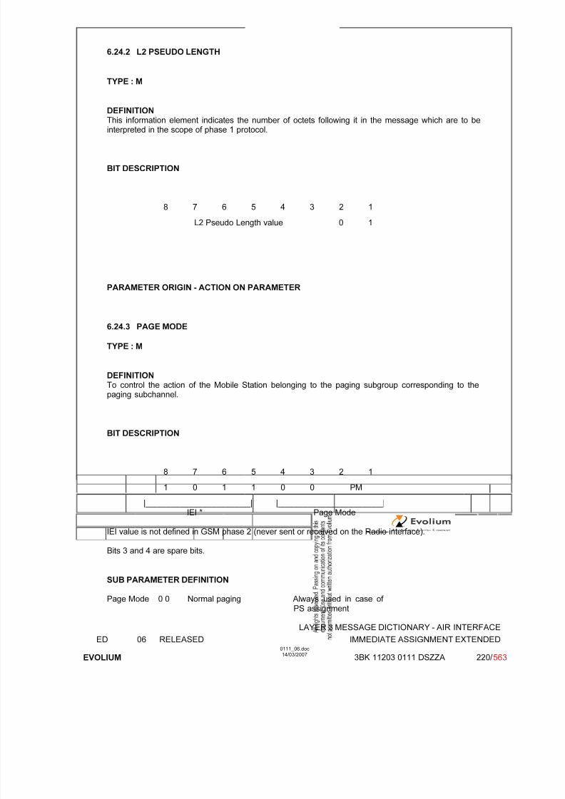
7/11/2019 1. Layer3 Air Interface Messages 0111_06
http://slidepdf.com/reader/full/1-layer3-air-interface-messages-011106 220/562
LAYER 3 MESSAGE DICTIONARY - AIR INTERFACE
ED 06 RELEASED IMMEDIATE ASSIGNMENT EXTENDED
EVOLIUM
0111_06.doc14/03/2007
3BK 11203 0111 DSZZA 220/ 563
6.24.2 L2 PSEUDO LENGTH
TYPE : M
DEFINITION
This information element indicates the number of octets following it in the message which are to beinterpreted in the scope of phase 1 protocol.
BIT DESCRIPTION
8 7 6 5 4 3 2 1
L2 Pseudo Length value 0 1
PARAMETER ORIGIN - ACTION ON PARAMETER
6.24.3 PAGE MODE
TYPE : M
DEFINITIONTo control the action of the Mobile Station belonging to the paging subgroup corresponding to thepaging subchannel.
BIT DESCRIPTION
8 7 6 5 4 3 2 1
1 0 1 1 0 0 PM|_______________________| |_______________________|
IEI * Page Mode
IEI value is not defined in GSM phase 2 (never sent or received on the Radio interface).
Bits 3 and 4 are spare bits.
SUB PARAMETER DEFINITION
Page Mode 0 0 Normal paging Always used in case of PS assignment

7/11/2019 1. Layer3 Air Interface Messages 0111_06
http://slidepdf.com/reader/full/1-layer3-air-interface-messages-011106 221/562
LAYER 3 MESSAGE DICTIONARY - AIR INTERFACE
ED 06 RELEASED IMMEDIATE ASSIGNMENT EXTENDED
EVOLIUM
0111_06.doc14/03/2007
3BK 11203 0111 DSZZA 221/ 563
0 1 Extended paging Not used1 0 Paging - Reorganisation Not used1 1 Same as before Always used in case of
CS assignment
PARAMETER ORIGIN - ACTION ON PARAMETER
6.24.4 CHANNEL DESCRIPTION
TYPE : M
DEFINITION
To provide a description of an allocatable channel together with its SACCH.
BIT DESCRIPTION
8 7 6 5 4 3 2 1
0 1 1 0 0 1 0 0 1
Channel type and TDMA offset TN 2
TSCH=1-> MAIO (high part) 3
H=0-> spare ARFCN (Hpart)
MAIO low part H S N 4
A R F C N (low part)
SUB PARAMETER DEFINITION
Octet 2
Channel type and TDMA offset.
Bits 8 7 6 5 40 0 0 0 1 TCH/F + ACCHs0 0 0 1 T TCH/H + ACCHs0 0 1 T T SDCCH/4 + SACCH/C4 or CBCH (SDCCH/4)0 1 T T T SDCCH/8 + SACCH/C8 or CBCH (SDCCH/8)all other values are reserved.
T bit indicates the Subchannel Number.
TN : Time slot (0 to 7)
Octets 3 and 4 :
TSC : Training Sequence Code (0 to 7)
H : "0" Single RF channel"1" RF hopping channel
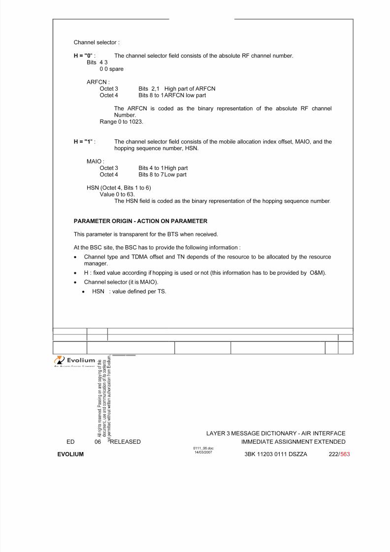
7/11/2019 1. Layer3 Air Interface Messages 0111_06
http://slidepdf.com/reader/full/1-layer3-air-interface-messages-011106 222/562
LAYER 3 MESSAGE DICTIONARY - AIR INTERFACE
ED 06 RELEASED IMMEDIATE ASSIGNMENT EXTENDED
EVOLIUM
0111_06.doc14/03/2007
3BK 11203 0111 DSZZA 222/ 563
Channel selector :
H = "0" : The channel selector field consists of the absolute RF channel number.Bits 4 3
0 0 spare
ARFCN :Octet 3 Bits 2,1 High part of ARFCNOctet 4 Bits 8 to 1 ARFCN low part
The ARFCN is coded as the binary representation of the absolute RF channelNumber.
Range 0 to 1023.
H = "1" : The channel selector field consists of the mobile allocation index offset, MAIO, and thehopping sequence number, HSN.
MAIO :
Octet 3 Bits 4 to 1 High partOctet 4 Bits 8 to 7 Low part
HSN (Octet 4, Bits 1 to 6)Value 0 to 63.
The HSN field is coded as the binary representation of the hopping sequence number.
PARAMETER ORIGIN - ACTION ON PARAMETER
This parameter is transparent for the BTS when received.
At the BSC site, the BSC has to provide the following information :
• Channel type and TDMA offset and TN depends of the resource to be allocated by the resourcemanager.
• H : fixed value according if hopping is used or not (this information has to be provided by O&M).
• Channel selector (it is MAIO).
• HSN : value defined per TS.
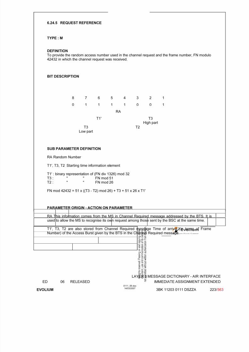
7/11/2019 1. Layer3 Air Interface Messages 0111_06
http://slidepdf.com/reader/full/1-layer3-air-interface-messages-011106 223/562
LAYER 3 MESSAGE DICTIONARY - AIR INTERFACE
ED 06 RELEASED IMMEDIATE ASSIGNMENT EXTENDED
EVOLIUM
0111_06.doc14/03/2007
3BK 11203 0111 DSZZA 223/ 563
6.24.5 REQUEST REFERENCE
TYPE : M
DEFINITION
To provide the random access number used in the channel request and the frame number, FN modulo42432 in which the channel request was received.
BIT DESCRIPTION
8 7 6 5 4 3 2 1
0 1 1 1 1 0 0 1
RA
T1' T3High part
T3Low part
T2
SUB PARAMETER DEFINITION
RA Random Number
T1', T3, T2 Starting time information element
T1' : binary representation of (FN div 1326) mod 32T3 : " " FN mod 51T2 : " " FN mod 26
FN mod 42432 = 51 x ((T3 - T2) mod 26) + T3 + 51 x 26 x T1'
PARAMETER ORIGIN - ACTION ON PARAMETER
RA This information comes from the MS in Channel Required message addressed by the BTS. It isused to allow the MS to recognise its own request among those sent by the BSC at the same time.
T1', T3, T2 are also stored from Channel Required message Time of arrival (in terms of FrameNumber) of the Access Burst given by the BTS in the Channel Required message.
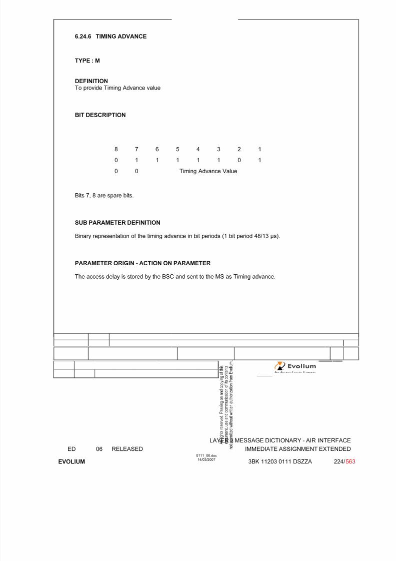
7/11/2019 1. Layer3 Air Interface Messages 0111_06
http://slidepdf.com/reader/full/1-layer3-air-interface-messages-011106 224/562
LAYER 3 MESSAGE DICTIONARY - AIR INTERFACE
ED 06 RELEASED IMMEDIATE ASSIGNMENT EXTENDED
EVOLIUM
0111_06.doc14/03/2007
3BK 11203 0111 DSZZA 224/ 563
6.24.6 TIMING ADVANCE
TYPE : M
DEFINITION
To provide Timing Advance value
BIT DESCRIPTION
8 7 6 5 4 3 2 1
0 1 1 1 1 1 0 1
0 0 Timing Advance Value
Bits 7, 8 are spare bits.
SUB PARAMETER DEFINITION
Binary representation of the timing advance in bit periods (1 bit period 48/13 s).
PARAMETER ORIGIN - ACTION ON PARAMETER
The access delay is stored by the BSC and sent to the MS as Timing advance.

7/11/2019 1. Layer3 Air Interface Messages 0111_06
http://slidepdf.com/reader/full/1-layer3-air-interface-messages-011106 225/562
LAYER 3 MESSAGE DICTIONARY - AIR INTERFACE
ED 06 RELEASED IMMEDIATE ASSIGNMENT EXTENDED
EVOLIUM
0111_06.doc14/03/2007
3BK 11203 0111 DSZZA 225/ 563
6.24.7 MOBILE ALLOCATION
TYPE : M
DEFINITIONTo provide the part of the RF channels belonging to the cell allocation which is used in the MobileStation hopping sequence.
BIT DESCRIPTION
8 7 6 5 4 3 2 1
0 1 1 1 0 0 1 0
Length of Mobile alloc. contents ≤ 4
MAC8n
MAC
8n-1
MAC
8n-7
:
MAC8
MAC1
SUB PARAMETER DEFINITION
MA length depends on the number of frequencies in the cell allocation frequency list ( up to 4 for 32frequencies ).
MA Ci : Mobile Allocation RF channel i - the RF channels represented in the MA C i bit
fields are those which in the cell channel description information element arecoded with "1" in the CA ARFCN N bit fields.
MA Ci = CA ARFCN N(i) i = 1,2...NF
(NF = Number of Frequencies in the CA frequency list).
For a RF channel belonging to the Mobile Allocation the MA Ci bit is coded with a"1", for a RF channel not belonging to the Mobile Allocation, the MA C bit is coded with a "0".
PARAMETER ORIGIN - ACTION ON PARAMETER
The parameter is transparent for the BTS when received from the BSC.Note: mandatory if Frequency Hopping system in used, otherwise the length is 0.
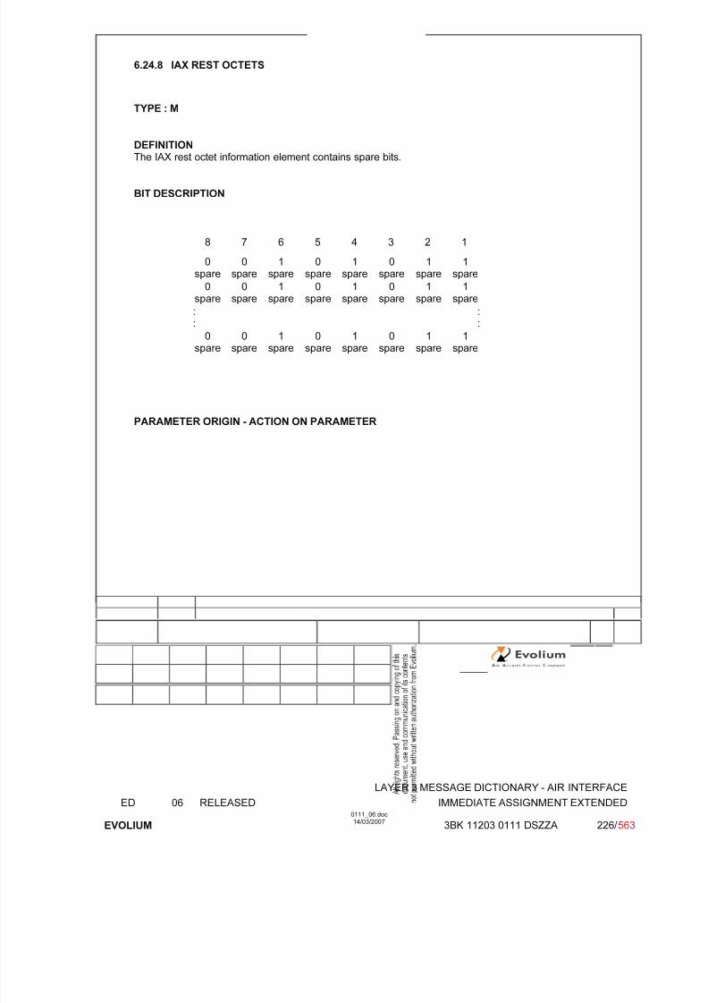
7/11/2019 1. Layer3 Air Interface Messages 0111_06
http://slidepdf.com/reader/full/1-layer3-air-interface-messages-011106 226/562
LAYER 3 MESSAGE DICTIONARY - AIR INTERFACE
ED 06 RELEASED IMMEDIATE ASSIGNMENT EXTENDED
EVOLIUM
0111_06.doc14/03/2007
3BK 11203 0111 DSZZA 226/ 563
6.24.8 IAX REST OCTETS
TYPE : M
DEFINITION
The IAX rest octet information element contains spare bits.
BIT DESCRIPTION
8 7 6 5 4 3 2 1
0spare
0spare
1spare
0spare
1spare
0spare
1spare
1spare
0spare
0spare
1spare
0spare
1spare
0spare
1spare
1spare
::
::
0spare
0spare
1spare
0spare
1spare
0spare
1spare
1spare
PARAMETER ORIGIN - ACTION ON PARAMETER

7/11/2019 1. Layer3 Air Interface Messages 0111_06
http://slidepdf.com/reader/full/1-layer3-air-interface-messages-011106 227/562
LAYER 3 MESSAGE DICTIONARY - AIR INTERFACE
ED 06 RELEASED IMMEDIATE ASSIGNMENT REJECT
EVOLIUM
0111_06.doc14/03/2007
3BK 11203 0111 DSZZA 227/ 563
6.25 IMMEDIATE ASSIGNMENT REJECT
NAME IMMEDIATE ASSIGNMENT REJECT
INTERFACE RADIO ABIS A
CHANNEL/ USAGE
CCCH/(AGCH-PCH)
3GPP-REF 44.018
FUNCTION This message is sent on the CCCH by the network to up to four MSs in idle modein order to delay their random access procedures.
DIRECTION From : BTS To : up to four MSs
INFORMATION ELEMENT NAME TYPE COMMENT LENGTH(byte)
INFORMATIONELEMENT
LISTL2 Pseudo LengthHeader Page modeSpareHalf OctetRequest Reference 1Wait Indication 1Request Reference 2Wait Indication 2Request Reference 3Wait Indication 3Request Reference 4
Wait Indication 4IAR Rest Octets
M V M V M V M V M V M V M V M V M V M V M V
M V M V
first MSfirst MS
second MSsecond MS
third MSthird MS
fourth MS
fourth MS
12½½3131313
13
IMPLEMENTATION MAXIMUM LENGTH 23
NORMAL SITUATION ABNORMAL SITUATION TIMER
FOLLOWINGEVENT
SPECIFDOC. REF.
Paging and Access Grant Control (ref. [1])Radio and link establishment (ref. [2])FBS - Radio Interface - RRM Sub-layer (PCC) (ref. [29])

7/11/2019 1. Layer3 Air Interface Messages 0111_06
http://slidepdf.com/reader/full/1-layer3-air-interface-messages-011106 228/562
LAYER 3 MESSAGE DICTIONARY - AIR INTERFACE
ED 06 RELEASED IMMEDIATE ASSIGNMENT REJECT
EVOLIUM
0111_06.doc14/03/2007
3BK 11203 0111 DSZZA 228/ 563
6.25.1 GENERAL DESCRIPTION
8 7 6 5 4 3 2 1
L2 Pseudo length L2 Pseudo Length 0 1
0 0 0 0 0 1 1 00 0 1 1 1 0 1 0
Page Mode 0 0 0 0 0 0 PM
Request RA
Reference T1' T3 High Part
1 T3 Low part T2
Wait Indication 1 T3122 timeout value
Request RA
Reference T1' T3 High Part
2 T3 Low part T2
Wait Indication 2 T3122 timeout value
Request RA
Reference T1' T3 High Part
3 T3 Low part T2
Wait Indication 3 T3122 timeout value
Request RA
Reference T1' T3 High Part
4 T3 Low part T2
Wait Indication 4 T3122 timeout value
IAR Rest Octets0
spare0
spare1
spare0
spare1
spare0
spare1
spare1
spare
0spare
0spare
1spare
0spare
1spare
0spare
1spare
1spare
0spare
0spare
1spare
0spare
1spare
0spare
1spare
1spare
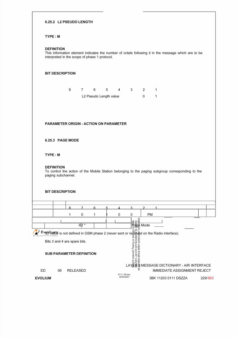
7/11/2019 1. Layer3 Air Interface Messages 0111_06
http://slidepdf.com/reader/full/1-layer3-air-interface-messages-011106 229/562
LAYER 3 MESSAGE DICTIONARY - AIR INTERFACE
ED 06 RELEASED IMMEDIATE ASSIGNMENT REJECT
EVOLIUM
0111_06.doc14/03/2007
3BK 11203 0111 DSZZA 229/ 563
6.25.2 L2 PSEUDO LENGTH
TYPE : M
DEFINITION
This information element indicates the number of octets following it in the message which are to beinterpreted in the scope of phase 1 protocol.
BIT DESCRIPTION
8 7 6 5 4 3 2 1
L2 Pseudo Length value 0 1
PARAMETER ORIGIN - ACTION ON PARAMETER
6.25.3 PAGE MODE
TYPE : M
DEFINITIONTo control the action of the Mobile Station belonging to the paging subgroup corresponding to thepaging subchannel.
BIT DESCRIPTION
8 7 6 5 4 3 2 1
1 0 1 1 0 0 PM
|_______________________| |________________________|IEI * Page Mode
IEI value is not defined in GSM phase 2 (never sent or received on the Radio interface).
Bits 3 and 4 are spare bits.
SUB PARAMETER DEFINITION

7/11/2019 1. Layer3 Air Interface Messages 0111_06
http://slidepdf.com/reader/full/1-layer3-air-interface-messages-011106 230/562
LAYER 3 MESSAGE DICTIONARY - AIR INTERFACE
ED 06 RELEASED IMMEDIATE ASSIGNMENT REJECT
EVOLIUM
0111_06.doc14/03/2007
3BK 11203 0111 DSZZA 230/ 563
Page Mode 0 0 Normal paging Always usedin case of PSassignment
0 1 Extended paging Not used1 0 Paging - Reorganisation Not used1 1 Same as before Always used
in case of CS
assignment
PARAMETER ORIGIN - ACTION ON PARAMETER
6.25.4 REQUEST REFERENCE
TYPE : M
DEFINITIONTo provide the random access number used in the channel request and the frame number, FN modulo42432 in which the channel request was received.
BIT DESCRIPTION
8 7 6 5 4 3 2 1
0 1 1 1 1 0 0 1
RA
T1' T3High part
T3Low part
T2
SUB PARAMETER DEFINITION
RA Random Number When set to the value ‘0111 1111’, the RA information of the Request Reference i IE indicates that anExtended RA i field may be included in the IAR Rest Octets. The mobile station shall use theinformation in the Extended RA i field to identify the Immediate Assignment Reject messagecorresponding to an EGPRS Packet Channel Request message.
T1', T3, T2 Starting time information element
T1' : binary representation of (FN div 1326) mod 32T3 : " " FN mod 51T2 : " " FN mod 26
FN mod 42432 = 51 x ((T3 - T2) mod 26) + T3 + 51 x 26 x T1'
7/11/2019 1. Layer3 Air Interface Messages 0111_06
http://slidepdf.com/reader/full/1-layer3-air-interface-messages-011106 231/562
LAYER 3 MESSAGE DICTIONARY - AIR INTERFACE
ED 06 RELEASED IMMEDIATE ASSIGNMENT REJECT
EVOLIUM
0111_06.doc14/03/2007
3BK 11203 0111 DSZZA 231/ 563
PARAMETER ORIGIN - ACTION ON PARAMETER
RA: This information comes from the MS in Channel Required message addressed by the BTS. It isused to allow the MS to recognise its own request among those sent by the BSC at the same time.
T1', T3, T2 are also stored from Channel Required message Time of arrival (in terms of FrameNumber) of the Access Burst given by the BTS in the Channel Required message.

7/11/2019 1. Layer3 Air Interface Messages 0111_06
http://slidepdf.com/reader/full/1-layer3-air-interface-messages-011106 232/562
LAYER 3 MESSAGE DICTIONARY - AIR INTERFACE
ED 06 RELEASED IMMEDIATE ASSIGNMENT REJECT
EVOLIUM
0111_06.doc14/03/2007
3BK 11203 0111 DSZZA 232/ 563
6.25.5 WAIT INDICATION
TYPE : M
DEFINITION
This information element indicates the number of seconds the MS shall wait before sending another random access.
BIT DESCRIPTION
8 7 6 5 4 3 2 1
T3122 / T3142 timeout value (Note 1)
Note 1: When IMMEDIATE ASSIGNMENT REJECT message is for RR connection establishmentthen this IE contains the timer value for T3122. If IMMEDIATE ASSIGNMENT REJECTmessage is for TBF establishment for GPRS MS (in case of saturated PDCHs or of TFI lack)then this IE contain the timer value for T3142 (Note that T3142 is named WI_PR in the AlcatelBSS).
PARAMETER ORIGIN - ACTION ON PARAMETER
6.25.6 IAR REST OCTETS
TYPE : M
DEFINITIONThe IAR rest octet information element contains spare bits when the RA information of all RequestReference IE is not set to ‘0111 1111’.
Otherwise, when the RA information of the Request Reference i IE is set to ‘0111 1111’, then theExtended RA i field is included in the IAR rest octet IE, see below.
BIT DESCRIPTION
<IAR Rest Octets> ::={ 0 | 1 < Extended RA 1 : bit (5) > }{ 0 | 1 < Extended RA 2 : bit (5) > }{ 0 | 1 < Extended RA 3 : bit (5) > }{ 0 | 1 < Extended RA 4 : bit (5) > }<spare padding> ;
7/11/2019 1. Layer3 Air Interface Messages 0111_06
http://slidepdf.com/reader/full/1-layer3-air-interface-messages-011106 233/562
LAYER 3 MESSAGE DICTIONARY - AIR INTERFACE
ED 06 RELEASED IMMEDIATE ASSIGNMENT REJECT
EVOLIUM
0111_06.doc14/03/2007
3BK 11203 0111 DSZZA 233/ 563
The Extended RA i (5 bits) is the Extended Random Access information related to the RequestReference i (i within the range 1...4).These are unformatted 5 bit fields, whose contents are coded as the 5 least significant bits of theEGPRS PACKET CHANNEL REQUEST message.
PARAMETER ORIGIN - ACTION ON PARAMETER

7/11/2019 1. Layer3 Air Interface Messages 0111_06
http://slidepdf.com/reader/full/1-layer3-air-interface-messages-011106 234/562
LAYER 3 MESSAGE DICTIONARY - AIR INTERFACE
ED 06 RELEASED IMMEDIATE SETUP
EVOLIUM
0111_06.doc14/03/2007
3BK 11203 0111 DSZZA 234/ 563
6.26 IMMEDIATE SETUP
NAME IMMEDIATE SETUP
INTERFACE RADIO ABIS A
CHANNEL/ USAGE
SDCCH/FACCH BTS Transparent
3GPP-REF 44.068 NA
FUNCTION The BSC is only non transparent to the classmark information.
DIRECTION From: MS To: BSC
INFORMATION ELEMENT NAME TYPE COMMENT LENGTH(byte)
INFORMATIONELEMENT
LISTHeader Spare half octetCiphering key sequence number Mobile Station ClassmarkMobile IdentityGroup identity
M V M V M LV M LV M V
2½½4
2-94
IMPLEMENTATION MAXIMUM LENGTH 20
NORMAL SITUATION ABNORMAL SITUATION TIMER
FOLLOWINGEVENT
SPECIFDOC. REF.
ASCI Functional Specification (ref. [36])

7/11/2019 1. Layer3 Air Interface Messages 0111_06
http://slidepdf.com/reader/full/1-layer3-air-interface-messages-011106 235/562
LAYER 3 MESSAGE DICTIONARY - AIR INTERFACE
ED 06 RELEASED IMMEDIATE SETUP
EVOLIUM
0111_06.doc14/03/2007
3BK 11203 0111 DSZZA 235/ 563
6.26.1 GENERAL DESCRIPTION
8 7 6 5 4 3 2 1
0 0 0 0 0 0 0 0
0 N(SD) 1 1 0 0 0 1
Spare half octetSpare half octet andCiphering key
sequence number 0 0 0 0
Ciphering key sequence number
Length of MS classmark 2 contents
Mobile StationClassmark 2
0spare
Revisionlevel
ES-IND
A5/1 RF power Capability
0
spare
PS
Capa.
SS Screen.
Indicator
SM.
cap VBS VGCS
FC
CM3 0spare
LCSVA
CAP
UCS2 SoLSA CMSP A5/3 A5/2
Length of Mobile Identity contents
ID digit 1 OEI Type of ID
Mobile ID digit 3 ID digit 2
Identity ... ...
ID digit p+1 ID digit p
Group identity
Call reference
6.26.2 CIPHERING KEY SEQUENCE NUMBER
TYPE M
DEFINITIONIdentification of the ciphering key Kc which is stored in the Mobile Station without invoking theauthentification procedure.
BIT DESCRIPTION
8 7 6 5 4 3 2 1
Spare half octet
0 0 0 0
0 key sequence

7/11/2019 1. Layer3 Air Interface Messages 0111_06
http://slidepdf.com/reader/full/1-layer3-air-interface-messages-011106 236/562
LAYER 3 MESSAGE DICTIONARY - AIR INTERFACE
ED 06 RELEASED IMMEDIATE SETUP
EVOLIUM
0111_06.doc14/03/2007
3BK 11203 0111 DSZZA 236/ 563
Bit 4 is spare bit.
SUB PARAMETER DEFINITION
Key sequence: value 0 to 6: Possible values for ciphering key sequence number
value 7: no key is available (MS to network)Reserved (network to MS).
PARAMETER ORIGIN - ACTION ON PARAMETER
BSC is transparent to this parameter.
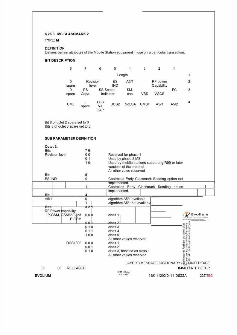
7/11/2019 1. Layer3 Air Interface Messages 0111_06
http://slidepdf.com/reader/full/1-layer3-air-interface-messages-011106 237/562
LAYER 3 MESSAGE DICTIONARY - AIR INTERFACE
ED 06 RELEASED IMMEDIATE SETUP
EVOLIUM
0111_06.doc14/03/2007
3BK 11203 0111 DSZZA 237/ 563
6.26.3 MS CLASSMARK 2
TYPE: M
DEFINITION
Defines certain attributes of the Mobile Station equipment in use on a particular transaction.
BIT DESCRIPTION
8 7 6 5 4 3 2 1
Length 1
0spare
Revisionlevel
ESIND
A5/1 RF power Capability
2
0spare
PSCapa.
SS Screen.Indicator
SM.cap VBS VGCS
FC 3
CM3 0spare
LCSVA
CAP
UCS2 SoLSA CMSP A5/3 A5/2 4
Bit 8 of octet 2 spare set to 0Bits 8 of octet 3 spare set to 0
SUB PARAMETER DEFINITION
Octet 2:Bits 7 6
Revision level 0 0 Reserved for phase 1 0 1 Used by phase 2 MS 1 0 Used by mobile stations supporting R99 or later
versions of the protocol All other value reserved
Bit 5ES-IND 0 Controlled Early Classmark Sending option not
implemented.1 Controlled Early Classmark Sending option
implemented.Bit 4A5/1 0 algorithm A5/1 available
1 algorithm A5/1 not available.
Bits 3 2 1RF Power capability
P-GSM, GSM850 andE-GSM
0 0 0 class 1
0 0 1 class 20 1 0 class 30 1 1 class 41 0 0 class 5
All other values reservedDCS1800 0 0 0 class 1
0 0 1 class 20 1 0 class 3, handled as class 1
All other values reserved

7/11/2019 1. Layer3 Air Interface Messages 0111_06
http://slidepdf.com/reader/full/1-layer3-air-interface-messages-011106 238/562
LAYER 3 MESSAGE DICTIONARY - AIR INTERFACE
ED 06 RELEASED IMMEDIATE SETUP
EVOLIUM
0111_06.doc14/03/2007
3BK 11203 0111 DSZZA 238/ 563
DCS1900 0 0 0 class 10 0 1 class 20 1 0 class 3, handled as class 1
All other values reserved
Octet 3:Bit 7PS Capability 0 PS capability not present
1 PS capability present
Bits 6 5SS Screening Indicator 0 0 Defined in GSM 04.80
0 1 Defined in GSM 04.801 0 Defined in GSM 04.801 1 Defined in GSM 04.80
Bit 4SM Capability 0 MS does not support mobile terminated point to point
SMS.1 MS supports mobile terminated point to point SMS.
Bit 3VBS Voice BroadcastService
0 no VBS capability or no notifications wanted
1 VBS capability and notifications wantedNot implemented in the BSS.
Bit 2VGCS Voice GroupCall Service
0 no VGCS capability or no notifications wanted
1 VGCS capability and notifications wanted
Bit 1FC FrequencyCapability
GSM900 0 The MS does not support the extension band G1 inaddition to the primary GSM band.
1 The MS does support the extension band G1.GSM850, DCS1800,
DCS19000 Reserved for future use
Note: only FC is checked in this release and only in GSM900 configuration.
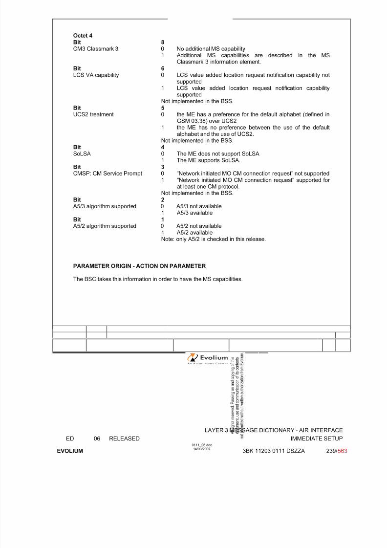
7/11/2019 1. Layer3 Air Interface Messages 0111_06
http://slidepdf.com/reader/full/1-layer3-air-interface-messages-011106 239/562
LAYER 3 MESSAGE DICTIONARY - AIR INTERFACE
ED 06 RELEASED IMMEDIATE SETUP
EVOLIUM
0111_06.doc14/03/2007
3BK 11203 0111 DSZZA 239/ 563
Octet 4Bit 8CM3 Classmark 3 0 No additional MS capability
1 Additional MS capabilities are described in the MSClassmark 3 information element.
Bit 6LCS VA capability 0 LCS value added location request notification capability not
supported1 LCS value added location request notification capabilitysupported
Not implemented in the BSS.Bit 5UCS2 treatment 0 the ME has a preference for the default alphabet (defined in
GSM 03.38) over UCS21 the ME has no preference between the use of the default
alphabet and the use of UCS2.Not implemented in the BSS.
Bit 4SoLSA 0 The ME does not support SoLSA
1 The ME supports SoLSA.
Bit 3CMSP: CM Service Prompt 0 "Network initiated MO CM connection request" not supported1 "Network initiated MO CM connection request" supported for
at least one CM protocol.Not implemented in the BSS.
Bit 2A5/3 algorithm supported 0 A5/3 not available
1 A5/3 available
Bit 1A5/2 algorithm supported 0 A5/2 not available
1 A5/2 availableNote: only A5/2 is checked in this release.
PARAMETER ORIGIN - ACTION ON PARAMETER
The BSC takes this information in order to have the MS capabilities.
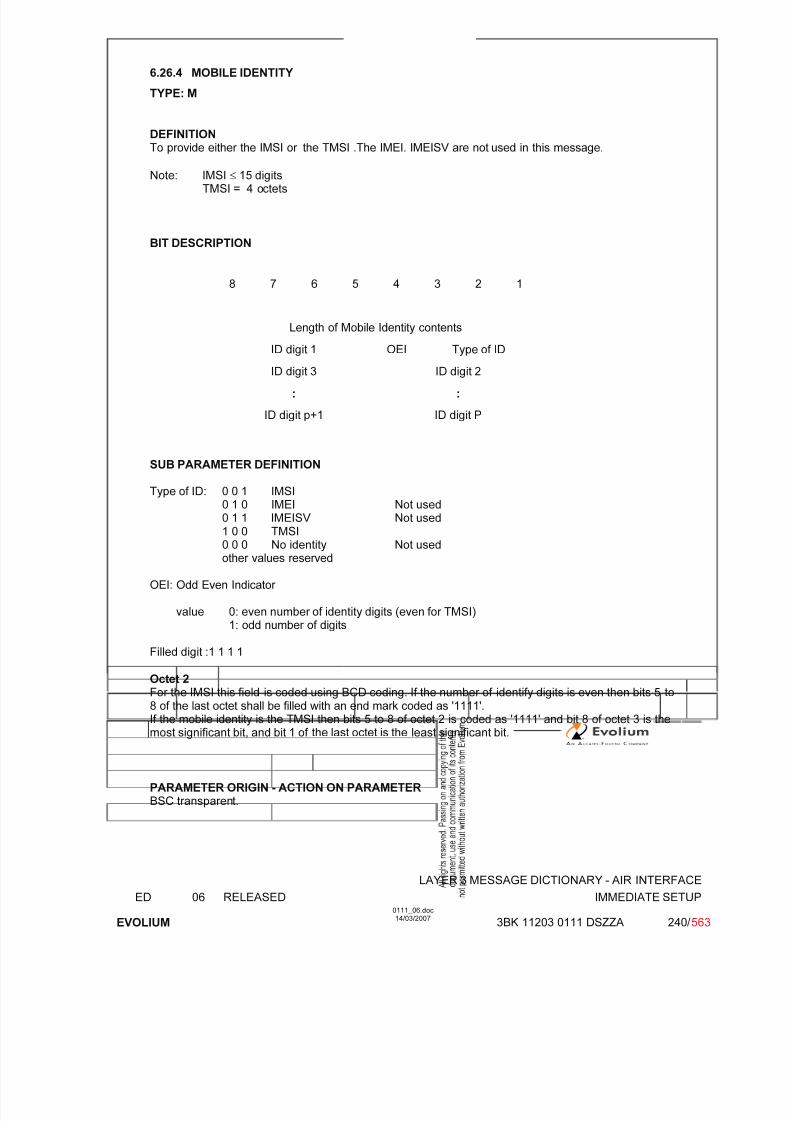
7/11/2019 1. Layer3 Air Interface Messages 0111_06
http://slidepdf.com/reader/full/1-layer3-air-interface-messages-011106 240/562
LAYER 3 MESSAGE DICTIONARY - AIR INTERFACE
ED 06 RELEASED IMMEDIATE SETUP
EVOLIUM
0111_06.doc14/03/2007
3BK 11203 0111 DSZZA 240/ 563
6.26.4 MOBILE IDENTITY
TYPE: M
DEFINITIONTo provide either the IMSI or the TMSI .The IMEI. IMEISV are not used in this message.
Note: IMSI ≤ 15 digitsTMSI = 4 octets
BIT DESCRIPTION
8 7 6 5 4 3 2 1
Length of Mobile Identity contents
ID digit 1 OEI Type of ID
ID digit 3 ID digit 2
: :
ID digit p+1 ID digit P
SUB PARAMETER DEFINITION
Type of ID: 0 0 1 IMSI0 1 0 IMEI Not used
0 1 1 IMEISV Not used1 0 0 TMSI0 0 0 No identity Not usedother values reserved
OEI: Odd Even Indicator
value 0: even number of identity digits (even for TMSI)1: odd number of digits
Filled digit :1 1 1 1
Octet 2
For the IMSI this field is coded using BCD coding. If the number of identify digits is even then bits 5 to8 of the last octet shall be filled with an end mark coded as '1111'.If the mobile identity is the TMSI then bits 5 to 8 of octet 2 is coded as '1111' and bit 8 of octet 3 is themost significant bit, and bit 1 of the last octet is the least significant bit.
PARAMETER ORIGIN - ACTION ON PARAMETERBSC transparent.
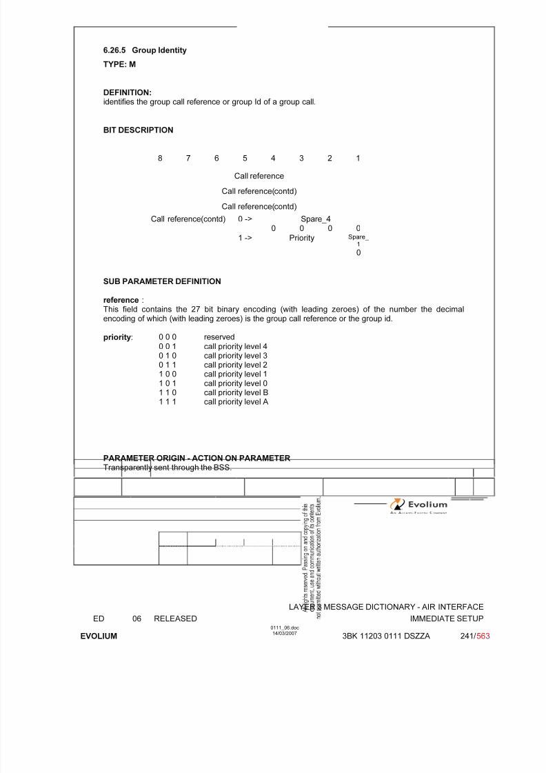
7/11/2019 1. Layer3 Air Interface Messages 0111_06
http://slidepdf.com/reader/full/1-layer3-air-interface-messages-011106 241/562
LAYER 3 MESSAGE DICTIONARY - AIR INTERFACE
ED 06 RELEASED IMMEDIATE SETUP
EVOLIUM
0111_06.doc14/03/2007
3BK 11203 0111 DSZZA 241/ 563
6.26.5 Group Identity
TYPE: M
DEFINITION:identifies the group call reference or group Id of a group call.
BIT DESCRIPTION
8 7 6 5 4 3 2 1
Call reference
Call reference(contd)
Call reference(contd)
Spare_40 ->0 0 0 0
Call reference(contd)
1 -> Priority Spare_ 1
0
SUB PARAMETER DEFINITION
reference :This field contains the 27 bit binary encoding (with leading zeroes) of the number the decimalencoding of which (with leading zeroes) is the group call reference or the group id.
priority: 0 0 0 reserved
0 0 1 call priority level 4
0 1 0 call priority level 30 1 1 call priority level 21 0 0 call priority level 11 0 1 call priority level 01 1 0 call priority level B1 1 1 call priority level A
PARAMETER ORIGIN - ACTION ON PARAMETERTransparently sent through the BSS.
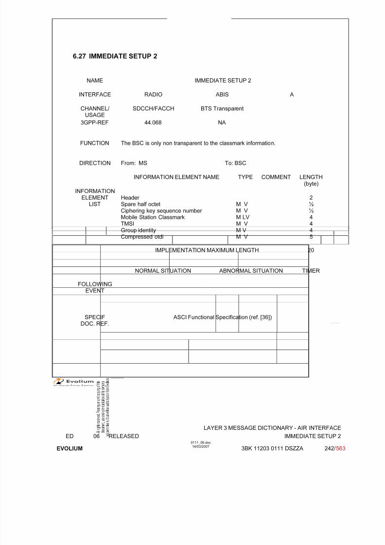
7/11/2019 1. Layer3 Air Interface Messages 0111_06
http://slidepdf.com/reader/full/1-layer3-air-interface-messages-011106 242/562
LAYER 3 MESSAGE DICTIONARY - AIR INTERFACE
ED 06 RELEASED IMMEDIATE SETUP 2
EVOLIUM
0111_06.doc14/03/2007
3BK 11203 0111 DSZZA 242/ 563
6.27 IMMEDIATE SETUP 2
NAME IMMEDIATE SETUP 2
INTERFACE RADIO ABIS A
CHANNEL/ USAGE
SDCCH/FACCH BTS Transparent
3GPP-REF 44.068 NA
FUNCTION The BSC is only non transparent to the classmark information.
DIRECTION From: MS To: BSC
INFORMATION ELEMENT NAME TYPE COMMENT LENGTH(byte)
INFORMATIONELEMENT
LISTHeader Spare half octetCiphering key sequence number Mobile Station ClassmarkTMSIGroup identityCompressed otdi
M V M V M LV M V M V M V
2½½4445
IMPLEMENTATION MAXIMUM LENGTH 20
NORMAL SITUATION ABNORMAL SITUATION TIMER
FOLLOWINGEVENT
SPECIFDOC. REF.
ASCI Functional Specification (ref. [36])

7/11/2019 1. Layer3 Air Interface Messages 0111_06
http://slidepdf.com/reader/full/1-layer3-air-interface-messages-011106 243/562
LAYER 3 MESSAGE DICTIONARY - AIR INTERFACE
ED 06 RELEASED IMMEDIATE SETUP 2
EVOLIUM
0111_06.doc14/03/2007
3BK 11203 0111 DSZZA 243/ 563
6.27.1 GENERAL DESCRIPTION
8 7 6 5 4 3 2 1
0 0 0 0 0 0 0 0
0 N(SD) 1 1 1 0 1 1
Spare half octetSpare half octet andCiphering key
sequence number 0 0 0 0
Ciphering key sequence number
Length of MS classmark 2 contents
Mobile StationClassmark 2
0spare
Revisionlevel
ES-IND
A5/1 RF power Capability
0
spare
PS
Capa.
SS Screen.
Indicator
SM.
cap VBS VGCS
FC
CM3 0spare
LCSVA
CAP
UCS2 SoLSA CMSP A5/3 A5/2
TMSI/P-TMSI value
TMSI/P-TMSI value (contd)
TMSI TMSI/P-TMSI value (contd)
TMSI/P-TMSI value (contd)
Group identity
Call reference
Compressed otdi
Compressed otdi
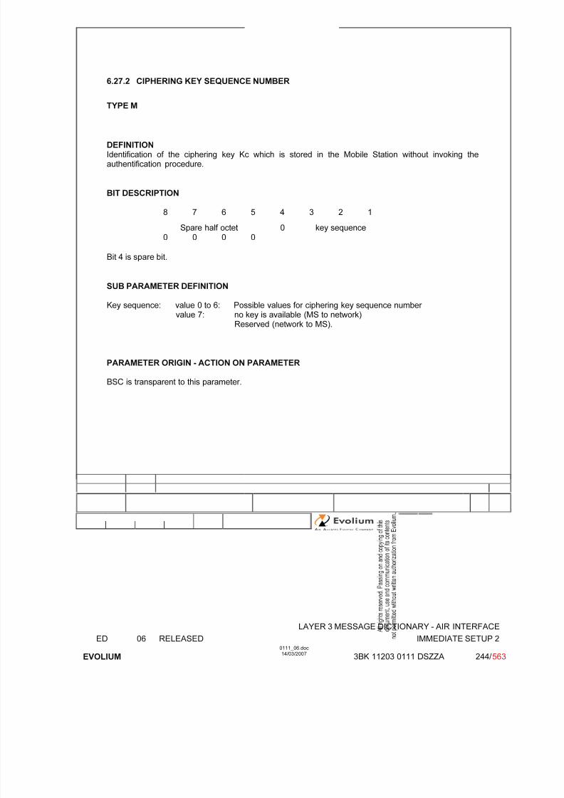
7/11/2019 1. Layer3 Air Interface Messages 0111_06
http://slidepdf.com/reader/full/1-layer3-air-interface-messages-011106 244/562
LAYER 3 MESSAGE DICTIONARY - AIR INTERFACE
ED 06 RELEASED IMMEDIATE SETUP 2
EVOLIUM
0111_06.doc14/03/2007
3BK 11203 0111 DSZZA 244/ 563
6.27.2 CIPHERING KEY SEQUENCE NUMBER
TYPE M
DEFINITIONIdentification of the ciphering key Kc which is stored in the Mobile Station without invoking theauthentification procedure.
BIT DESCRIPTION
8 7 6 5 4 3 2 1
Spare half octet0 0 0 0
0 key sequence
Bit 4 is spare bit.
SUB PARAMETER DEFINITION
Key sequence: value 0 to 6: Possible values for ciphering key sequence number value 7: no key is available (MS to network)
Reserved (network to MS).
PARAMETER ORIGIN - ACTION ON PARAMETER
BSC is transparent to this parameter.

7/11/2019 1. Layer3 Air Interface Messages 0111_06
http://slidepdf.com/reader/full/1-layer3-air-interface-messages-011106 245/562
LAYER 3 MESSAGE DICTIONARY - AIR INTERFACE
ED 06 RELEASED IMMEDIATE SETUP 2
EVOLIUM
0111_06.doc14/03/2007
3BK 11203 0111 DSZZA 245/ 563
6.27.3 MS CLASSMARK 2
TYPE: M
DEFINITION
Defines certain attributes of the Mobile Station equipment in use on a particular transaction.
BIT DESCRIPTION
8 7 6 5 4 3 2 1
Length 1
0spare
Revisionlevel
ESIND
A5/1 RF power Capability
2
0spare
PSCapa.
SS Screen.Indicator
SM.cap VBS VGCS
FC 3
CM3 0spare
LCSVA
CAP
UCS2 SoLSA CMSP A5/3 A5/2 4
Bit 8 of octet 2 spare set to 0Bits 8 of octet 3 spare set to 0
SUB PARAMETER DEFINITION
Octet 2:Bits 7 6
Revision level 0 0 Reserved for phase 1 0 1 Used by phase 2 MS 1 0 Used by mobile stations supporting R99 or later
versions of the protocol All other value reserved
Bit 5ES-IND 0 Controlled Early Classmark Sending option not
implemented.1 Controlled Early Classmark Sending option
implemented.Bit 4A5/1 0 algorithm A5/1 available
1 algorithm A5/1 not available.
Bits 3 2 1RF Power capability
P-GSM, GSM850 andE-GSM
0 0 0 class 1
0 0 1 class 20 1 0 class 30 1 1 class 41 0 0 class 5
All other values reservedDCS1800 0 0 0 class 1
0 0 1 class 20 1 0 class 3, handled as class 1
All other values reserved
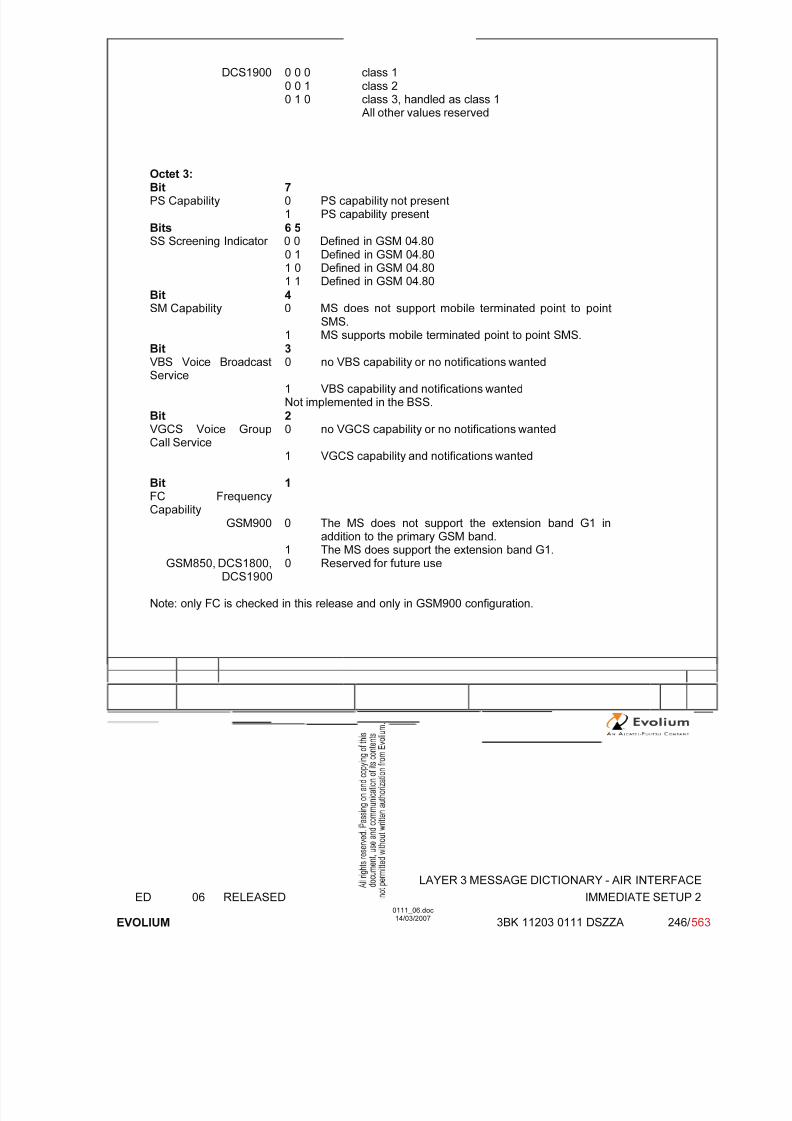
7/11/2019 1. Layer3 Air Interface Messages 0111_06
http://slidepdf.com/reader/full/1-layer3-air-interface-messages-011106 246/562
LAYER 3 MESSAGE DICTIONARY - AIR INTERFACE
ED 06 RELEASED IMMEDIATE SETUP 2
EVOLIUM
0111_06.doc14/03/2007
3BK 11203 0111 DSZZA 246/ 563
DCS1900 0 0 0 class 10 0 1 class 20 1 0 class 3, handled as class 1
All other values reserved
Octet 3:Bit 7PS Capability 0 PS capability not present
1 PS capability present
Bits 6 5SS Screening Indicator 0 0 Defined in GSM 04.80
0 1 Defined in GSM 04.801 0 Defined in GSM 04.801 1 Defined in GSM 04.80
Bit 4SM Capability 0 MS does not support mobile terminated point to point
SMS.1 MS supports mobile terminated point to point SMS.
Bit 3VBS Voice BroadcastService
0 no VBS capability or no notifications wanted
1 VBS capability and notifications wantedNot implemented in the BSS.
Bit 2VGCS Voice GroupCall Service
0 no VGCS capability or no notifications wanted
1 VGCS capability and notifications wanted
Bit 1FC FrequencyCapability
GSM900 0 The MS does not support the extension band G1 inaddition to the primary GSM band.
1 The MS does support the extension band G1.GSM850, DCS1800,
DCS19000 Reserved for future use
Note: only FC is checked in this release and only in GSM900 configuration.

7/11/2019 1. Layer3 Air Interface Messages 0111_06
http://slidepdf.com/reader/full/1-layer3-air-interface-messages-011106 247/562
LAYER 3 MESSAGE DICTIONARY - AIR INTERFACE
ED 06 RELEASED IMMEDIATE SETUP 2
EVOLIUM
0111_06.doc14/03/2007
3BK 11203 0111 DSZZA 247/ 563
Octet 4Bit 8CM3 Classmark 3 0 No additional MS capability
1 Additional MS capabilities are described in the MSClassmark 3 information element.
Bit 6LCS VA capability 0 LCS value added location request notification capability not
supported1 LCS value added location request notification capabilitysupported
Not implemented in the BSS.Bit 5UCS2 treatment 0 the ME has a preference for the default alphabet (defined in
GSM 03.38) over UCS21 the ME has no preference between the use of the default
alphabet and the use of UCS2.Not implemented in the BSS.
Bit 4SoLSA 0 The ME does not support SoLSA
1 The ME supports SoLSA.
Bit 3CMSP: CM Service Prompt 0 "Network initiated MO CM connection request" not supported1 "Network initiated MO CM connection request" supported for
at least one CM protocol.Not implemented in the BSS.
Bit 2A5/3 algorithm supported 0 A5/3 not available
1 A5/3 available
Bit 1A5/2 algorithm supported 0 A5/2 not available
1 A5/2 availableNote: only A5/2 is checked in this release.
PARAMETER ORIGIN - ACTION ON PARAMETER
The BSC takes this information in order to have the MS capabilities.
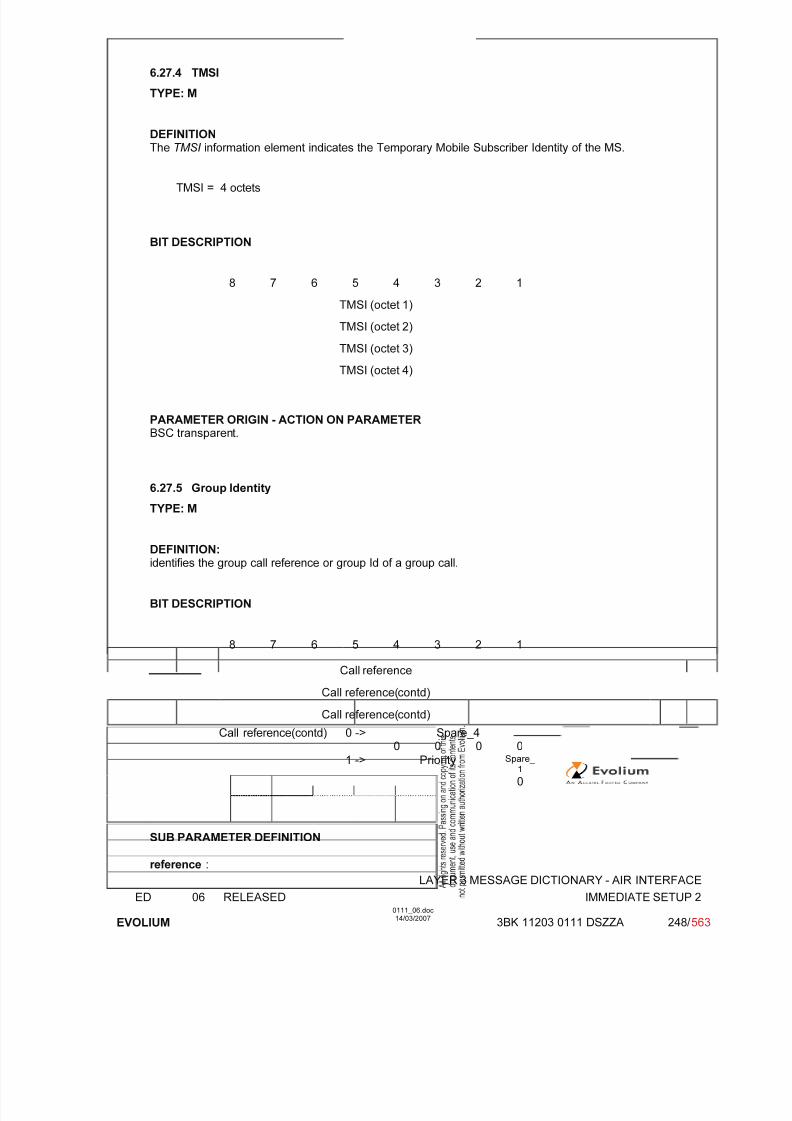
7/11/2019 1. Layer3 Air Interface Messages 0111_06
http://slidepdf.com/reader/full/1-layer3-air-interface-messages-011106 248/562
LAYER 3 MESSAGE DICTIONARY - AIR INTERFACE
ED 06 RELEASED IMMEDIATE SETUP 2
EVOLIUM
0111_06.doc14/03/2007
3BK 11203 0111 DSZZA 248/ 563
6.27.4 TMSI
TYPE: M
DEFINITIONThe TMSI information element indicates the Temporary Mobile Subscriber Identity of the MS.
TMSI = 4 octets
BIT DESCRIPTION
8 7 6 5 4 3 2 1
TMSI (octet 1)
TMSI (octet 2)
TMSI (octet 3)
TMSI (octet 4)
PARAMETER ORIGIN - ACTION ON PARAMETERBSC transparent.
6.27.5 Group Identity
TYPE: M
DEFINITION:identifies the group call reference or group Id of a group call.
BIT DESCRIPTION
8 7 6 5 4 3 2 1
Call reference
Call reference(contd)
Call reference(contd)
Spare_40 ->0 0 0 0
Call reference(contd)
1 -> Priority Spare_ 1
0
SUB PARAMETER DEFINITION
reference :

7/11/2019 1. Layer3 Air Interface Messages 0111_06
http://slidepdf.com/reader/full/1-layer3-air-interface-messages-011106 249/562
LAYER 3 MESSAGE DICTIONARY - AIR INTERFACE
ED 06 RELEASED IMMEDIATE SETUP 2
EVOLIUM
0111_06.doc14/03/2007
3BK 11203 0111 DSZZA 249/ 563
This field contains the 27 bit binary encoding (with leading zeroes) of the number the decimalencoding of which (with leading zeroes) is the group call reference or the group id (see 3GPPTS 23.003).
priority: 0 0 0 reserved0 0 1 call priority level 40 1 0 call priority level 3
0 1 1 call priority level 21 0 0 call priority level 11 0 1 call priority level 01 1 0 call priority level B1 1 1 call priority level A
PARAMETER ORIGIN - ACTION ON PARAMETERTransparently sent through the BSS.
6.27.6 Compressed otdi
TYPE M
DEFINITIONThis information element contains compressed originator-to-dispatcher information.
BIT DESCRIPTION
8 7 6 5 4 3 2 1
Compressed otdi (octet1)
Compressed otdi (octet2)
Compressed otdi (octet3)
Compressed otdi (octet4)
Compressed otdi (octet5)
PARAMETER ORIGIN - ACTION ON PARAMETER
BSC is transparent to this parameter.

7/11/2019 1. Layer3 Air Interface Messages 0111_06
http://slidepdf.com/reader/full/1-layer3-air-interface-messages-011106 250/562
LAYER 3 MESSAGE DICTIONARY - AIR INTERFACE
ED 06 RELEASED IMSI DETACH INDICATION
EVOLIUM
0111_06.doc14/03/2007
3BK 11203 0111 DSZZA 250/ 563
6.28 IMSI DETACH INDICATION
NAME IMSI DETACH INDICATION
INTERFACE RADIO ABIS A
CHANNEL/ USAGE
SDCCH BTS Transparent
3GPP-REF 24.008
FUNCTION To set the deactivation indication in the network (MSC). The BSS is only nontransparent to the classmark information
DIRECTION From: MS To: BSC
INFORMATION ELEMENT NAME TYPE COMMENT LENGTH
INFORMATIONELEMENT
LISTHeader Mobile station classmark1Mobile identity
M V M LV
21
2-9
IMPLEMENTATION MAXIMUM LENGTH 4-12
NORMAL SITUATION ABNORMAL SITUATION TIMER
FOLLOWINGEVENT
SPECIFDOC. REF.
Radio Link Establishment (ref. [2])

7/11/2019 1. Layer3 Air Interface Messages 0111_06
http://slidepdf.com/reader/full/1-layer3-air-interface-messages-011106 251/562
LAYER 3 MESSAGE DICTIONARY - AIR INTERFACE
ED 06 RELEASED IMSI DETACH INDICATION
EVOLIUM
0111_06.doc14/03/2007
3BK 11203 0111 DSZZA 251/ 563
6.28.1 GENERAL DESCRIPTION
MS accessing Rel98 or older networks
8 7 6 5 4 3 2 1
0 0 0 0 0 1 0 1
0 N(SD) 0 0 0 0 0 1
Mobile stationclassmark 1
0 Revision level ES-IND
A5/1 RF power capab.
Length of Mobile Identity contents
Mobile ID digit 1 OEI Type of ID
Identity ID digit 3 ID digit 2
: :
ID digit p+1 ID digit P
MS accessing Rel99 or newer networks
8 7 6 5 4 3 2 1
0 0 0 0 0 1 0 1
N(SD) or 0 0 0 0 0 0 1
Mobile stationclassmark 1
0 Revision level ES-IND
A5/1 RF power capab.
Length of Mobile Identity contents
Mobile ID digit 1 OEI Type of ID
Identity ID digit 3 ID digit 2
: :
ID digit p+1 ID digit P
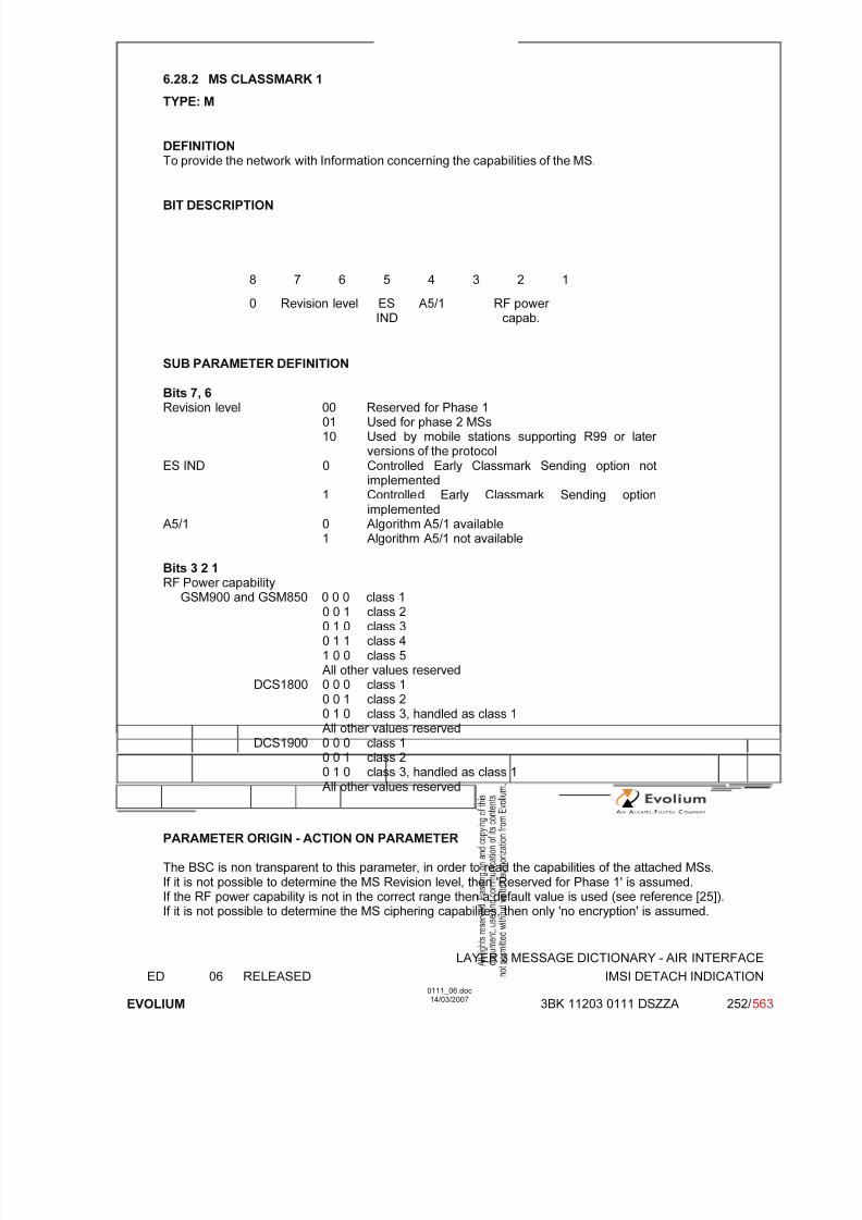
7/11/2019 1. Layer3 Air Interface Messages 0111_06
http://slidepdf.com/reader/full/1-layer3-air-interface-messages-011106 252/562
LAYER 3 MESSAGE DICTIONARY - AIR INTERFACE
ED 06 RELEASED IMSI DETACH INDICATION
EVOLIUM
0111_06.doc14/03/2007
3BK 11203 0111 DSZZA 252/ 563
6.28.2 MS CLASSMARK 1
TYPE: M
DEFINITIONTo provide the network with Information concerning the capabilities of the MS.
BIT DESCRIPTION
8 7 6 5 4 3 2 1
0 Revision level ESIND
A5/1 RF power capab.
SUB PARAMETER DEFINITION
Bits 7, 6Revision level 00 Reserved for Phase 1
01 Used for phase 2 MSs10 Used by mobile stations supporting R99 or later
versions of the protocolES IND 0 Controlled Early Classmark Sending option not
implemented1 Controlled Early Classmark Sending option
implementedA5/1 0 Algorithm A5/1 available
1 Algorithm A5/1 not available
Bits 3 2 1RF Power capability
GSM900 and GSM850 0 0 0 class 10 0 1 class 20 1 0 class 30 1 1 class 41 0 0 class 5All other values reserved
DCS1800 0 0 0 class 10 0 1 class 20 1 0 class 3, handled as class 1All other values reserved
DCS1900 0 0 0 class 10 0 1 class 20 1 0 class 3, handled as class 1All other values reserved
PARAMETER ORIGIN - ACTION ON PARAMETER
The BSC is non transparent to this parameter, in order to read the capabilities of the attached MSs.If it is not possible to determine the MS Revision level, then 'Reserved for Phase 1' is assumed.If the RF power capability is not in the correct range then a default value is used (see reference [25]).If it is not possible to determine the MS ciphering capabilites, then only 'no encryption' is assumed.

7/11/2019 1. Layer3 Air Interface Messages 0111_06
http://slidepdf.com/reader/full/1-layer3-air-interface-messages-011106 253/562
LAYER 3 MESSAGE DICTIONARY - AIR INTERFACE
ED 06 RELEASED IMSI DETACH INDICATION
EVOLIUM
0111_06.doc14/03/2007
3BK 11203 0111 DSZZA 253/ 563
6.28.3 MOBILE IDENTITY
TYPE: M
DEFINITIONTo provide either the IMSI, the TMSI or the IMEI. IMEISV is not used in the IMSI Detach Indicationmessage.
Note IMSI ≤ 15 digitsTMSI = 4 octetsIMEI = 15 digits
BIT DESCRIPTION
8 7 6 5 4 3 2 1
Length of Mobile Identity contents
ID digit 1 OEI Type of IDID digit 3 ID digit 2
: :
ID digit p+1 ID digit P
SUB PARAMETER DEFINITION
Type of ID: 0 0 1 IMSI0 1 0 IMEI0 1 1 IMEISV Not used1 0 0 TMSI0 0 0 No identity Not usedother values reserved
OEI: Odd Even Indicator
value 0: even number of identity digits (even for TMSI)1: odd number of digits
Filled digit :1 1 1 1
Octet 2
For the IMSI, IMEI and the IMEISV, this field is coded using BCD coding (number 0 through 9). If thenumber of identify digits is even then bits 5 to 8 of the last octet shall be filled with an end mark codedas '1111'.If the mobile identity is the TMSI then bits 5 to 8 of octet 2 is coded as '1111' and bit 8 of octet 3 is themost significant bit, and bit 1 of last octet is the least significant bit.
PARAMETER ORIGIN - ACTION ON PARAMETERBSC transparent.

7/11/2019 1. Layer3 Air Interface Messages 0111_06
http://slidepdf.com/reader/full/1-layer3-air-interface-messages-011106 254/562
LAYER 3 MESSAGE DICTIONARY - AIR INTERFACE
ED 06 RELEASED INTER SYSTEM TO UTRAN HANDOVER COMMAND
EVOLIUM
0111_06.doc14/03/2007
3BK 11203 0111 DSZZA 254/ 563
6.29 INTER SYSTEM TO UTRAN HANDOVER COMMAND
NAME INTER SYSTEM TO UTRAN HANDOVER COMMAND
INTERFACE RADIO ABIS A
CHANNEL/ USAGE
FACCH/SDCCH Transparent
3GPP-REF 44.018 NA
FUNCTIONThis message is sent on the main DCCH by the network to the mobile station tochange the dedicated channel in GSM to a dedicated channel configuration inUTRAN.
DIRECTION From BSS To MS
INFORMATION ELEMENT NAME TYPE COMMENT LENGTH(byte)
INFORMATIONELEMENT
LISTHeader Handover to UTRAN Command
M V M LV
22-n
IMPLEMENTATION MAXIMUM LENGTH 4-n
NORMAL SITUATION ABNORMAL SITUATION TIMER
FOLLOWINGEVENT
2G to 3G handover executionprocedure.
T3121
SPECIFDOC. REF.
External channel changes [7]
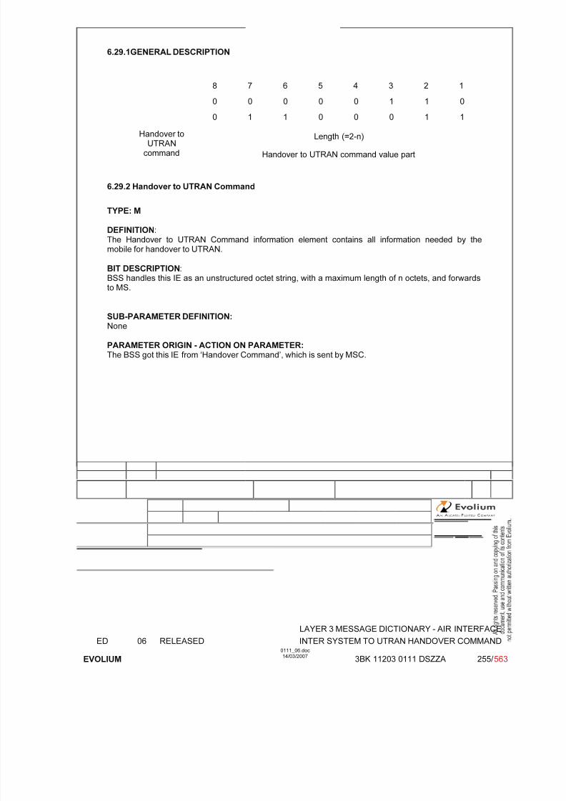
7/11/2019 1. Layer3 Air Interface Messages 0111_06
http://slidepdf.com/reader/full/1-layer3-air-interface-messages-011106 255/562
LAYER 3 MESSAGE DICTIONARY - AIR INTERFACE
ED 06 RELEASED INTER SYSTEM TO UTRAN HANDOVER COMMAND
EVOLIUM
0111_06.doc14/03/2007
3BK 11203 0111 DSZZA 255/ 563
6.29.1GENERAL DESCRIPTION
8 7 6 5 4 3 2 1
0 0 0 0 0 1 1 0
0 1 1 0 0 0 1 1
Length (=2-n)Handover toUTRAN
command Handover to UTRAN command value part
6.29.2 Handover to UTRAN Command
TYPE: M
DEFINITION:The Handover to UTRAN Command information element contains all information needed by the
mobile for handover to UTRAN.
BIT DESCRIPTION:BSS handles this IE as an unstructured octet string, with a maximum length of n octets, and forwardsto MS.
SUB-PARAMETER DEFINITION: None
PARAMETER ORIGIN - ACTION ON PARAMETER:The BSS got this IE from ‘Handover Command’, which is sent by MSC.

7/11/2019 1. Layer3 Air Interface Messages 0111_06
http://slidepdf.com/reader/full/1-layer3-air-interface-messages-011106 256/562
LAYER 3 MESSAGE DICTIONARY - AIR INTERFACE
ED 06 RELEASED LOCATION UPDATING REQUEST
EVOLIUM
0111_06.doc14/03/2007
3BK 11203 0111 DSZZA 256/ 563
6.30 LOCATION UPDATING REQUEST
NAME LOCATION UPDATING REQUEST
INTERFACE RADIO ABIS A
CHANNEL/ USAGE
Main DCCH BTS Transparent
3GPP-REF 24.008
FUNCTION The BSC is only non transparent to the classmark information in order to knowthe MS capabilities.
DIRECTION From: MS To: BSC
INFORMATION ELEMENT NAME TYPE COMMENT LENGTH(byte)
INFORMATIONELEMENT
LISTHeader Location updating typeCiphering key sequence number Location area identificationMobile station classmark1Mobile IdentityMobile station classmark for UMTS
M V M V M V M V M LV
M TLV Not used
2½½51
2-9
IMPLEMENTATION MAXIMUM LENGTH 11-18
NORMAL SITUATION ABNORMAL SITUATION TIMER
FOLLOWINGEVENT
SPECIFDOC. REF.
Radio Link Establishment (ref. [2])
1/2 means half-octet.

7/11/2019 1. Layer3 Air Interface Messages 0111_06
http://slidepdf.com/reader/full/1-layer3-air-interface-messages-011106 257/562
LAYER 3 MESSAGE DICTIONARY - AIR INTERFACE
ED 06 RELEASED LOCATION UPDATING REQUEST
EVOLIUM
0111_06.doc14/03/2007
3BK 11203 0111 DSZZA 257/ 563
6.30.1 GENERAL DESCRIPTION
MS accessing Rel.98 or older network
0 0 0 0 0 1 0 1
0 N(SD) 0 0 1 0 0 0
Ciphering Key Seq& loc. upd. type
0 key sequence FOR 0 LUT
MCC Digit 2 MCC Digit 1
Location Area MNC Digit 3 (Note) MCC Digit 3
Identification MNC Digit 2 MNC Digit 1
LAC
LAC (continued)
Mobile stationClassmark 1
0 Revision level ES-IND
A5/1 RF power capab.
Length of Mobile Identity contents
Mobile ID digit 1 OEI Type of ID
Identity ID digit 3 ID digit 2
.... ......
ID digit p+1 ID digit P
MS accessing Rel.99 or newer network
0 0 0 0 0 1 0 1
N(SD) or 0 0 0 1 0 0 0
Ciphering Key Seq& loc. upd. type
0 key sequence FOR 0 LUT
MCC Digit 2 MCC Digit 1
Location Area MNC Digit 3 (Note) MCC Digit 3
Identification MNC Digit 2 MNC Digit 1
LAC
LAC (continued)
Mobile stationClassmark 1
0 Revision level ES-IND
A5/1 RF power capab.
Length of Mobile Identity contents
Mobile ID digit 1 OEI Type of ID
Identity ID digit 3 ID digit 2
.... ......
ID digit p+1 ID digit P

7/11/2019 1. Layer3 Air Interface Messages 0111_06
http://slidepdf.com/reader/full/1-layer3-air-interface-messages-011106 258/562
LAYER 3 MESSAGE DICTIONARY - AIR INTERFACE
ED 06 RELEASED LOCATION UPDATING REQUEST
EVOLIUM
0111_06.doc14/03/2007
3BK 11203 0111 DSZZA 258/ 563
Note 3 digits MNC is supported. Note that in case where only two digits MNC is used, the field“MNC Digit 3” shall be filled in with “1111”.
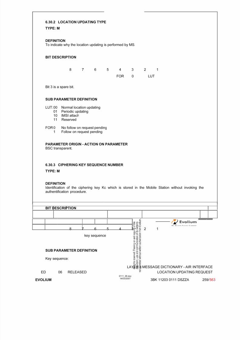
7/11/2019 1. Layer3 Air Interface Messages 0111_06
http://slidepdf.com/reader/full/1-layer3-air-interface-messages-011106 259/562
LAYER 3 MESSAGE DICTIONARY - AIR INTERFACE
ED 06 RELEASED LOCATION UPDATING REQUEST
EVOLIUM
0111_06.doc14/03/2007
3BK 11203 0111 DSZZA 259/ 563
6.30.2 LOCATION UPDATING TYPE
TYPE: M
DEFINITIONTo indicate why the location updating is performed by MS.
BIT DESCRIPTION
8 7 6 5 4 3 2 1
FOR 0 LUT
Bit 3 is a spare bit.
SUB PARAMETER DEFINITION
LUT: 00 Normal location updating01 Periodic updating10 IMSI attach11 Reserved
FOR 0 No follow on request pending1 Follow on request pending
PARAMETER ORIGIN - ACTION ON PARAMETERBSC transparent.
6.30.3 CIPHERING KEY SEQUENCE NUMBER
TYPE: M
DEFINITIONIdentification of the ciphering key Kc which is stored in the Mobile Station without invoking theauthentification procedure.
BIT DESCRIPTION
8 7 6 5 4 3 2 1
key sequence
SUB PARAMETER DEFINITION
Key sequence:

7/11/2019 1. Layer3 Air Interface Messages 0111_06
http://slidepdf.com/reader/full/1-layer3-air-interface-messages-011106 260/562
LAYER 3 MESSAGE DICTIONARY - AIR INTERFACE
ED 06 RELEASED LOCATION UPDATING REQUEST
EVOLIUM
0111_06.doc14/03/2007
3BK 11203 0111 DSZZA 260/ 563
value 000 : Possible values for ciphering key sequence number.:
110value 111 : no key is available (MS to network)
Reserved (network to MS)
PARAMETER ORIGIN - ACTION ON PARAMETERBSC Transparent.
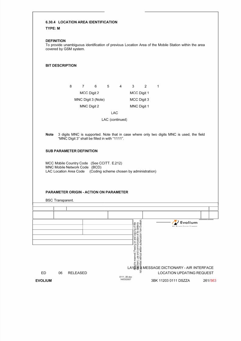
7/11/2019 1. Layer3 Air Interface Messages 0111_06
http://slidepdf.com/reader/full/1-layer3-air-interface-messages-011106 261/562
LAYER 3 MESSAGE DICTIONARY - AIR INTERFACE
ED 06 RELEASED LOCATION UPDATING REQUEST
EVOLIUM
0111_06.doc14/03/2007
3BK 11203 0111 DSZZA 261/ 563
6.30.4 LOCATION AREA IDENTIFICATION
TYPE: M
DEFINITIONTo provide unambiguous identification of previous Location Area of the Mobile Station within the areacovered by GSM system.
BIT DESCRIPTION
8 7 6 5 4 3 2 1
MCC Digit 2 MCC Digit 1
MNC Digit 3 (Note) MCC Digit 3
MNC Digit 2 MNC Digit 1
LAC
LAC (continued)
Note 3 digits MNC is supported. Note that in case where only two digits MNC is used, the field“MNC Digit 3” shall be filled in with “1111”.
SUB PARAMETER DEFINITION
MCC Mobile Country Code (See CCITT. E.212)MNC Mobile Network Code (BCD)LAC Location Area Code (Coding scheme chosen by administration)
PARAMETER ORIGIN - ACTION ON PARAMETER
BSC Transparent.

7/11/2019 1. Layer3 Air Interface Messages 0111_06
http://slidepdf.com/reader/full/1-layer3-air-interface-messages-011106 262/562
LAYER 3 MESSAGE DICTIONARY - AIR INTERFACE
ED 06 RELEASED LOCATION UPDATING REQUEST
EVOLIUM
0111_06.doc14/03/2007
3BK 11203 0111 DSZZA 262/ 563
6.30.5 MS CLASSMARK 1
TYPE: M
DEFINITIONTo provide the network with Information concerning aspects with both high and low priority of theMobile Station equipment.
BIT DESCRIPTION
8 7 6 5 4 3 2 1
0 Revision level ESIND
A5/1 RF power capab.
SUB PARAMETER DEFINITION
Revision level 00 Reserved for Phase 101 Used for phase 2 MSs10 Used by mobile stations supporting R99 or later versions of the
protocolES IND 0 Controlled Early Classmark Sending option not implemented
1 Controlled Early Classmark Sending option implementedA5/1 0 Algorithm A5/1 available
1 Algorithm A5/1 not availableRF Power capability
GSM900 and GSM850 0 0 0 class 10 0 1 class 20 1 0 class 30 1 1 class 41 0 0 class 5All other values reserved
DCS1800 0 0 0 class 10 0 1 class 20 1 0 class 3, handled as class 1All other values reserved
DCS1900 0 0 0 class 10 0 1 class 20 1 0 class 3, handled as class 1All other values reserved
PARAMETER ORIGIN - ACTION ON PARAMETER
The BSC is non transparent to this parameter, in order to read the capabilities of the attached MSs.If it is not possible to determine the MS Revision level, then 'Reserved for Phase 1' is assumed.If the RF power capability is not in the correct range then a default value is used (see reference [25]).If it is not possible to determine the MS ciphering capabilites, then only 'no encryption' is assumed.

7/11/2019 1. Layer3 Air Interface Messages 0111_06
http://slidepdf.com/reader/full/1-layer3-air-interface-messages-011106 263/562
LAYER 3 MESSAGE DICTIONARY - AIR INTERFACE
ED 06 RELEASED LOCATION UPDATING REQUEST
EVOLIUM
0111_06.doc14/03/2007
3BK 11203 0111 DSZZA 263/ 563
6.30.6 MOBILE IDENTITY
TYPE: M
DEFINITIONTo provide either the IMSI, the TMSI or the IMEI. IMEISV is not used in the Location UpdatingRequest message.
Note IMSI ≤ 15 digitsTMSI = 4 octetsIMEI = 15 digits
BIT DESCRIPTION
8 7 6 5 4 3 2 1
1 Length of Mobile Identity contents
2 ID digit 1 OEI Type of ID
3 ID digit 3 ID digit 2
: :
N ID digit p+1 ID digit P
SUB PARAMETER DEFINITION
Type of ID: 0 0 1 IMSI0 1 0 IMEI0 1 1 IMEISV 1 0 0 TMSI0 0 0 No identityother values reserved
OEI : Odd Even Indicator
value 0: even number of identity digits (even for TMSI)1: odd number of digits
Octet 2 For the IMSI, IMEI and the IMEISV, this field is coded using BCD coding (number 0 through 9). If thenumber of identify digits is even then bits 5 to 8 of the last octet shall be filled with an end mark codedas '1111'.If the mobile identity is the TMSI then bits 5 to 8 of octet 2 is coded as '1111' and bit 8 of octet 3 is themost significant bit, and bit 1 of last octet is the least significant bit.
PARAMETER ORIGIN - ACTION ON PARAMETER
BSC transparent.
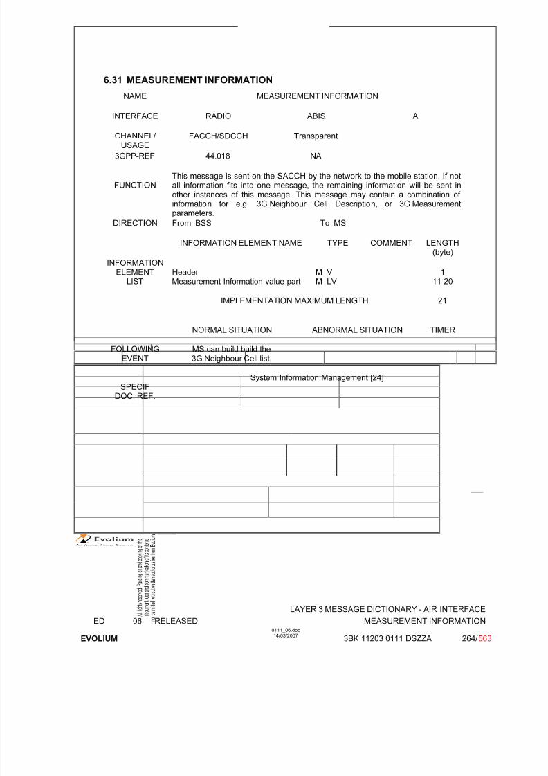
7/11/2019 1. Layer3 Air Interface Messages 0111_06
http://slidepdf.com/reader/full/1-layer3-air-interface-messages-011106 264/562
LAYER 3 MESSAGE DICTIONARY - AIR INTERFACE
ED 06 RELEASED MEASUREMENT INFORMATION
EVOLIUM
0111_06.doc14/03/2007
3BK 11203 0111 DSZZA 264/ 563
6.31 MEASUREMENT INFORMATION
NAME MEASUREMENT INFORMATION
INTERFACE RADIO ABIS A
CHANNEL/ USAGE
FACCH/SDCCH Transparent
3GPP-REF 44.018 NA
FUNCTIONThis message is sent on the SACCH by the network to the mobile station. If notall information fits into one message, the remaining information will be sent inother instances of this message. This message may contain a combination of information for e.g. 3G Neighbour Cell Description, or 3G Measurementparameters.
DIRECTION From BSS To MS
INFORMATION ELEMENT NAME TYPE COMMENT LENGTH(byte)
INFORMATIONELEMENT
LISTHeader Measurement Information value part
M V M LV
111-20
IMPLEMENTATION MAXIMUM LENGTH 21
NORMAL SITUATION ABNORMAL SITUATION TIMER
FOLLOWING
EVENT
MS can build build the
3G Neighbour Cell list.
SPECIFDOC. REF.
System Information Management [24]

7/11/2019 1. Layer3 Air Interface Messages 0111_06
http://slidepdf.com/reader/full/1-layer3-air-interface-messages-011106 265/562
LAYER 3 MESSAGE DICTIONARY - AIR INTERFACE
ED 06 RELEASED MEASUREMENT INFORMATION
EVOLIUM
0111_06.doc14/03/2007
3BK 11203 0111 DSZZA 265/ 563
6.30.1 GENERAL DESCRIPTION
8 7 6 5 4 3 2 1
"short header" RRshortPD
Message type Short layer 2header
Measurementinformation valuepart
See the table below for the detail
Message type = 0 0 1 0 1
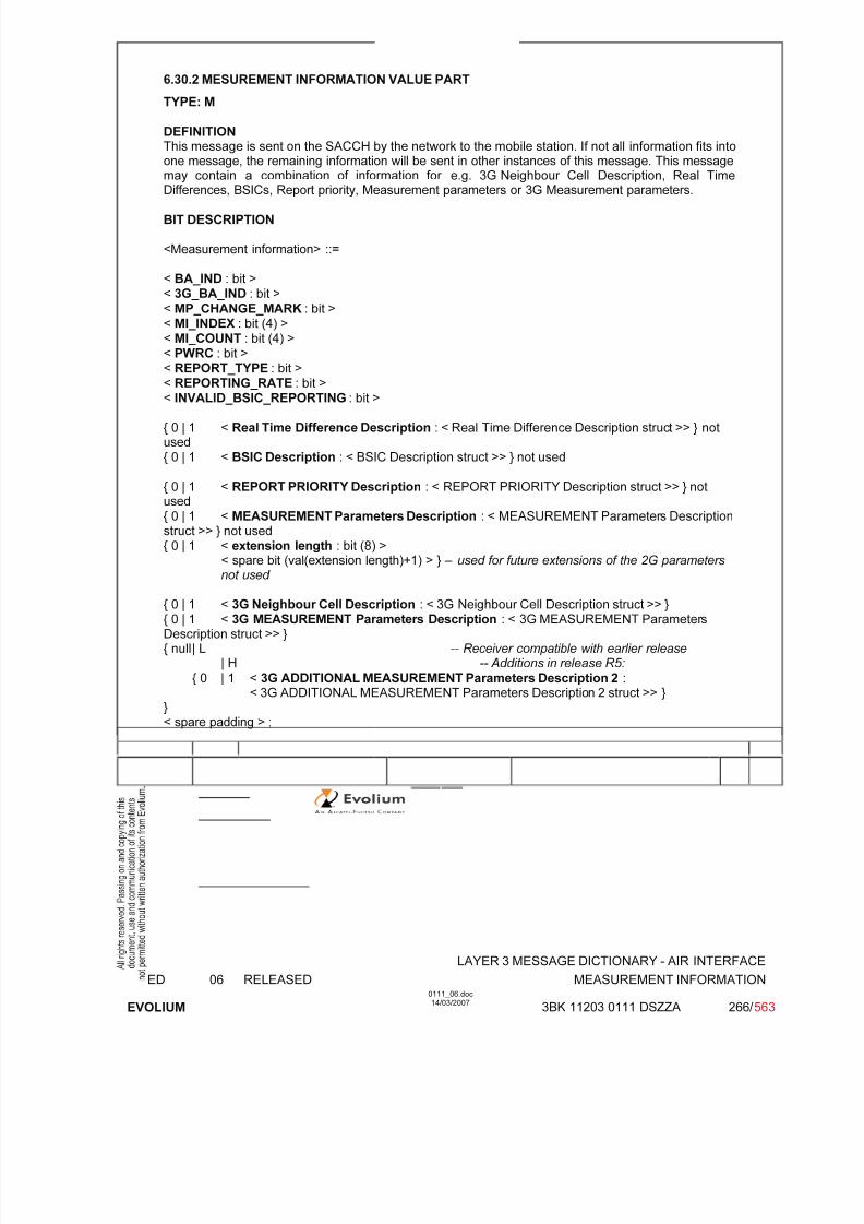
7/11/2019 1. Layer3 Air Interface Messages 0111_06
http://slidepdf.com/reader/full/1-layer3-air-interface-messages-011106 266/562
LAYER 3 MESSAGE DICTIONARY - AIR INTERFACE
ED 06 RELEASED MEASUREMENT INFORMATION
EVOLIUM
0111_06.doc14/03/2007
3BK 11203 0111 DSZZA 266/ 563
6.30.2 MESUREMENT INFORMATION VALUE PART
TYPE: M
DEFINITION This message is sent on the SACCH by the network to the mobile station. If not all information fits intoone message, the remaining information will be sent in other instances of this message. This messagemay contain a combination of information for e.g. 3G Neighbour Cell Description, Real Time
Differences, BSICs, Report priority, Measurement parameters or 3G Measurement parameters.
BIT DESCRIPTION
<Measurement information> ::=
< BA_IND : bit >< 3G_BA_IND : bit >
< MP_CHANGE_MARK : bit >< MI_INDEX : bit (4) >< MI_COUNT : bit (4) >< PWRC : bit >< REPORT_TYPE : bit >< REPORTING_RATE : bit >< INVALID_BSIC_REPORTING : bit >
{ 0 | 1 < Real Time Difference Description : < Real Time Difference Description struct >> } notused{ 0 | 1 < BSIC Description : < BSIC Description struct >> } not used
{ 0 | 1 < REPORT PRIORITY Description : < REPORT PRIORITY Description struct >> } notused{ 0 | 1 < MEASUREMENT Parameters Description : < MEASUREMENT Parameters Descriptionstruct >> } not used{ 0 | 1 < extension length : bit (8) >
< spare bit (val(extension length)+1) > } – used for future extensions of the 2G parametersnot used
{ 0 | 1 < 3G Neighbour Cell Description : < 3G Neighbour Cell Description struct >> }{ 0 | 1 < 3G MEASUREMENT Parameters Description : < 3G MEASUREMENT ParametersDescription struct >> }{ null | L -- Receiver compatible with earlier release
| H -- Additions in release R5:
{ 0 | 1 < 3G ADDITIONAL MEASUREMENT Parameters Description 2 :< 3G ADDITIONAL MEASUREMENT Parameters Description 2 struct >> }
}< spare padding > ;

7/11/2019 1. Layer3 Air Interface Messages 0111_06
http://slidepdf.com/reader/full/1-layer3-air-interface-messages-011106 267/562
LAYER 3 MESSAGE DICTIONARY - AIR INTERFACE
ED 06 RELEASED MEASUREMENT INFORMATION
EVOLIUM
0111_06.doc14/03/2007
3BK 11203 0111 DSZZA 267/ 563
8 7 6 5 4 3 2 1 OctetNumber
BA_IND
3G_BA _IND
MP_CHANGE_ MARK
MI_INDEX MI_COUNT
1
MI_COUNT PWRC REPORT_TYPE = 1
REPORTING _RATE
= 0
INVALID_BSIC_REPORTING = 0
RTD=0 2
BSICDESCRIPTION
= 0
REPORT_PRIORITY
= 0
Measur ement
Parameter
Description = 0
EXTENSION
LENGTH = 0
3G Neighbour cell description 3
3G Neighbour cell description with variable length 4..i
3G Neighbour cell description 3G MEASUREMENT ParametersDescription with variable length i+1
3G MEASUREMENT Parameters Description with variable length i+2 .. n
BA_IND: BCCH allocation sequence number indicationIt is needed to allow the network to discriminate measurement results related to different
GSM Neighbour Cell lists sent to the MS. The value of this parameter is reflected in theMEASUREMENT REPORT message.
3G_BA_IND: 3G sequence number The 3G_BA_IND parameter is needed to allow the network to discriminate measurement
results related to different 3G Neighbour Cell lists sent to the MS. The value of this parameter isreflected in MEASUREMENT REPORT message.
MP_CHANGE_MARK: measurement parameters change markThis parameter is used to indicate the MS a change of information concerning REPORT
PRIORITY, MEASUREMENT INFORMATION and 3G MEASUREMENT INFORMATION.
MI_INDEX and MI_COUNT:The purpose of the MI_INDEX and MI_COUNT fields is to indicate the number of individual
messages within the sequence of MEASUREMENT INFORMATION messages and to assign an indexto identify each of them. The MI_INDEX field is binary coded, range 0 to 15, and provides an index toidentify the individual MEASUREMENT INFORMATION message. The MI_COUNT field is binarycoded, range 0 to 15, and provides the MI_INDEX value for the last (highest indexed) message in thesequence of MEASUREMENT INFORMATION message.
PWRC: Power control indicator. same as e.g. SI3 &6.45.Bit: 0 MS shall include measurement on the BCCH carrier. PWRC is not set.
1 MS shall not include measurement on the BCCH carrier. PWRC is set.
REPORT_TYPE:This parameter is used to indicate to the mobile to use the Enhanced Measurement report
or Measurement report messages for reporting.Bit: 0 The MS shall use the Enhanced Measurement Report message for reporting if at least
one BSIC is allocated to each BA (list) frequency. Not used.1 The MS shall use the Measurement Report message for reporting.
REPORTING_RATE:
This parameter is used for measurements.

7/11/2019 1. Layer3 Air Interface Messages 0111_06
http://slidepdf.com/reader/full/1-layer3-air-interface-messages-011106 268/562
LAYER 3 MESSAGE DICTIONARY - AIR INTERFACE
ED 06 RELEASED MEASUREMENT INFORMATION
EVOLIUM
0111_06.doc14/03/2007
3BK 11203 0111 DSZZA 268/ 563
Bit:0 SACCH1 Not used.
INVALID_BSIC_REPORTING:This field specifies if cells with invalid BSIC and allowed NCC part of BSIC are allowed to be
reported or not.
Bit:0 Report on cells with invalid BSIC and allowed NCC part of BSIC is not allowed.1 Not used.
RTD: Real Time Difference DescriptionNot used.
BSIC Description:Used to create the GSM Neighbour Cell listNot used.
REPORT PRIORITY DESCRIPTION:Not used.
MEASUREMENT Parameters Description:Not used.
EXTENSION LENGTH: Used for future extensions of the 2G parameters.Not used.
3G NEIGHBOUR CELL DESCRIPTION< 3G Neighbour Cell Description struct > ::=
{ 0 | 1 < 3G_Wait : bit (3) > }
{ 0 | 1 < Index_Start_3G : bit (7) > }
{ 0 | 1 < Absolute_Index_Start_EMR : bit (7) > not used}{ 0 | 1 < UTRAN FDD Description : < UTRAN FDD Description struct >> }
{ 0 | 1 < UTRAN TDD Description : < UTRAN TDD Description struct >> not used}{ 0 | 1 < CDMA2000 Description : < CDMA2000 Description struct >> not used} ;
3G-WAIT (3 bits)When 3G_BA_IND is received in a changed state, this parameter indicates the number of instances of MEASUREMENT INFORMATION messages that contain 3G Neighbour CellDescription which shall be received before the MS reports on the new 3G Neighbour Cell list.Two different instances of MEASUREMENT INFORMATION messages are twoMEASUREMENT INFORMATION messages with different MI_INDEX.bit 3 2 10 0 0 1 instance that contain 3G Neighbour Cell Description shall be received0 0 1 2 instances that contain Neighbour Cell Description shall be received
::1 1 1 8 instances that contain Neighbour Cell description shall be received
Index_Start_3G (7 bit)This optional information element indicates the binary value of the first index to use to build thisinstance of the 3G Neighbour Cell list. In the first instance (i.e. when MI_INDEX = 0) thisparameter is not sent.
Absolute_Index_Start_EMR (7 bit)This parameter indicates in binary the value to be added to the indexes of the 3G Neighbour Cell list for reporting 3G Cells with the ENHANCED MEASUREMENT REPORT message. If different values are received for this parameter in different instances of this message, the

7/11/2019 1. Layer3 Air Interface Messages 0111_06
http://slidepdf.com/reader/full/1-layer3-air-interface-messages-011106 269/562
LAYER 3 MESSAGE DICTIONARY - AIR INTERFACE
ED 06 RELEASED MEASUREMENT INFORMATION
EVOLIUM
0111_06.doc14/03/2007
3BK 11203 0111 DSZZA 269/ 563
instance with the highest index shall be used. If this parameter is absent in all instances of themessage, the value "0" shall be used.0: Not used.
UTRAN FDD Description:< UTRAN FDD Description struct > ::={ 0 | 1 < Bandwidth_FDD : bit (3) > }
{ 1 < Repeated UTRAN FDD Neighbour Cells : < Repeated UTRAN FDD Neighbour Cellsstruct >> } ** 0 ;
Bandwidth_FDD (3bit field)This optional information element will be used for future releases of the protocol. Whenmissing, this indicates the present FDD bandwidth. When present, this shall not beconsidered as an error; indices of the 3G Neighbour Cell list shall be incrementedaccordingly.0: not used.
< Repeated UTRAN FDD Neighbour Cells struct > ::=0 < FDD-ARFCN : bit (14) > -- The value ‘1’ was used in an earlier version of
-- the protocol and shall not be used.
< FDD_Indic0 : bit >< NR_OF_FDD_CELLS : bit (5) >< FDD_CELL_INFORMATION Field : bit(p(NR_OF_FDD_CELLS)) > ;
FDD_ARFCN (14 bit field)This optional information element is defined as the UARFCN in 3GPP TS25.101.Set from O&M parameter.
FDD_Indic0, information 0 indicator (1 bit):This field indicates if the FDD_CELL_INFORMATION parameter value'0000000000' is a member of the set.Bit
0parameter value '0000000000' is not a member of the set1parameter value '0000000000' is a member of the setNOTE:This bit FDD_Indic0 is equivalent to the bit F0 bit in the frequency listinformation element. Refer to 3GPP TS44.018 10.5.2.13.
NR_OF_FDD_CELLS (5 bit field)This field defines the number of FDD_CELL_INFORMATION parameters.Set from O&M parameter.
FDD_CELL_INFORMATION Field (p bit field)This field allows to compute a set of 10-bit-long FDD_CELL_INFORMATIONparameters, re-using the Range 1024 format compression algorithm. Theconsecutive parameters of this field are concatenated, starting with w1, and
then w2, w3…The total number of bits p of this field depends on the value of the parameter NR_OF_FDD_CELLS = n, as follows:
n p n p n p n p0 0 5 44 10 81 15 1161 10 6 52 11 88 16 1222 19 7 60 12 95 17-31 03 28 8 67 13 1024 36 9 74 14 109
Note: in B9, n = 1..8.For each (10-bit-long) decoded Parameter, bits 1-9 are the Scrambling Codeand bit 10 is the corresponding Diversity Parameter.Bit 10 is the most significant bit.
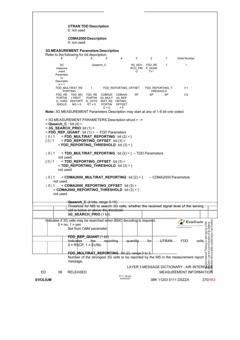
7/11/2019 1. Layer3 Air Interface Messages 0111_06
http://slidepdf.com/reader/full/1-layer3-air-interface-messages-011106 270/562
LAYER 3 MESSAGE DICTIONARY - AIR INTERFACE
ED 06 RELEASED MEASUREMENT INFORMATION
EVOLIUM
0111_06.doc14/03/2007
3BK 11203 0111 DSZZA 270/ 563
UTRAN TDD Description0: not used
CDMA2000 Description0: not used.
3G MEASUREMENT Parameters DescriptionRefer to the following for bit description.8 7 6 5 4 3 2 1 Octet Number
3G
measurement
Paramete
rsDescriptio
n = 1
Qsearch_C 3G_SEA
RCH_PRIO
FDD_RE
P_QUANT=1
1 I
FDD_MULTIRAT_REPORTING
1 FDD_REPORTING_OFFSET FDD_REPORTING_THRESHOLD
I+1
FDD_RE
PORTING_THRE
SHOLD
TDD_MU
LTIRAT_ REPORTI
NG = 0
TDD_RE
PORTING_OFFS
ET = 0
CDMA20
00_MULTIRAT_RE
PORTING = 0
CDMA20
00_REPORTING_
OFFSET= 0
SP SP SP I+2
Note: 3G MEASUREMENT Parameters Description may start at any of 1-8 bit one octect.
< 3G MEASUREMENT PARAMETERS Description struct > ::=< Qsearch_C : bit (4) >< 3G_SEARCH_PRIO: bit (1) >< FDD_REP_QUANT : bit (1) > -- FDD Parameters
{ 0 | 1 < FDD_MULTIRAT_REPORTING : bit (2) > }{ 0 | 1 < FDD_REPORTING_OFFSET : bit (3) >
< FDD_REPORTING_THRESHOLD : bit (3) > }
{ 0 | 1 < TDD_MULTIRAT_REPORTING : bit (2) > } -- TDD Parameters
not used.{ 0 | 1 < TDD_REPORTING_OFFSET : bit (3) >
< TDD_REPORTING_THRESHOLD : bit (3) > }not used.
{ 0 | 1 < CDMA2000_MULTIRAT_REPORTING : bit (2) > } -- CDMA2000 Parametersnot used.
{ 0 | 1 < CDMA2000_REPORTING_OFFSET : bit (3) >
< CDMA2000_REPORTING_THRESHOLD : bit (3) > } ;not used.
Qsearch_C (4 bits, range 0-15)Threshold for MS to search 3G cells, whether the received signal level of the serving
cell is below or above the threshold.3G_SEARCH_PRIO (1 bit)
Indicates if 3G cells may be searched when BSIC decoding is required,0 = no, 1 = yes
Set from O&M parameter.
FDD_REP_QUANT (1 bit) Indicates the reporting quantity for UTRAN FDD cells,0 = RSCP, 1 = Ec/No
FDD_MULTIRAT_REPORTING : bit (2), range 0 to 3.Number of the strongest 3G cells to be reported by the MS in the measurement report
message.
7/11/2019 1. Layer3 Air Interface Messages 0111_06
http://slidepdf.com/reader/full/1-layer3-air-interface-messages-011106 271/562
LAYER 3 MESSAGE DICTIONARY - AIR INTERFACE
ED 06 RELEASED MEASUREMENT INFORMATION
EVOLIUM
0111_06.doc14/03/2007
3BK 11203 0111 DSZZA 271/ 563
Set from O&M parameter.
FDD_REPORTING_OFFSET : bit (3)Offset that the MS shall apply to measurements before reporting.Set from O&M parameter.
FDD_REPORTING_THRESHOLD : bit (3)
Threshold above which the MS shall report the measurements.Set from O&M parameter.

7/11/2019 1. Layer3 Air Interface Messages 0111_06
http://slidepdf.com/reader/full/1-layer3-air-interface-messages-011106 272/562
LAYER 3 MESSAGE DICTIONARY - AIR INTERFACE
ED 06 RELEASED MEASUREMENT INFORMATION
EVOLIUM
0111_06.doc14/03/2007
3BK 11203 0111 DSZZA 272/ 563
Example for the maximum length for maximum 8 3G cells on maximum 3 UARFCN (2 UARFCN with 3cells, 1 UARFCN with 2 cells).
First Instance:
8 7 6 5 4 3 2 1 Octet Number
BA_IND 3G_BA_IND
MP_CHANGE_MA
RK
MI_INDEX = 0 MI_COUNT = 1
1
MI_COUNT PWRC REPORT
_TYPE
REPORTI
NG_RATE
INVALID_
BSIC_REPORTIN
G
RTD=0 2
BSICDESCRIP
TION=0
REPORT _PRIORI
TY=0
MEASUREMENT
PARAMETERS
DESCRIP
TION=0
EXTENSION
LENGTH=0
3GNeighbou
r celldescriptio
n=1
1 3G_WAIT 3
3G_WAIT Index_Start_3G =
0 (first
instance)
AbsoluteIndex
Start
EMR=0
UTRANFDD
Desc = 1
Bandwidth_FDD =
0
RepeatedUTRAN
FDD
Neighbour Cells =
1
0 FDD_ARFCN(1/3)
4
FDD_ARFCN(1/3) 5
FDD_ARFCN(1/3) FDD_Indi
c0
Nbr of FDD cells (e.g.
= 3)
6
Nbr of FDD cells FDD_CELL_INFORMATION Field 7
8
FDD_CELL_INFORMATION Field (e.g. = p(3) = 28 bits)9
FDD_CELL_INFORMATION Field RepeatedUTRAN
FDD
Neighbour Cells =
1
10
0 FDD_ARFCN(2/3) 11
FDD_ARFCN(2/3) FDD_Indi
c0
12
Nbr of FDD cells (e.g. = 3) FDD_CELL_INFORMATION Field 13
14
15FDD_CELL_INFORMATION Field (e.g. = p(3) = 28 bits)
16
FDD_CELL_INFORMATIO
N Field
End of RepeatedUtran
FDD
Neighbour cells = 0
UTRANTDDDescriptio
n = 0
CDMA2000Descriptio
n = 0
3Gmeasurement
Paramete
rsDescriptio
n = 0 (noenough
place)
SP SP SP 17

7/11/2019 1. Layer3 Air Interface Messages 0111_06
http://slidepdf.com/reader/full/1-layer3-air-interface-messages-011106 273/562
LAYER 3 MESSAGE DICTIONARY - AIR INTERFACE
ED 06 RELEASED MEASUREMENT INFORMATION
EVOLIUM
0111_06.doc14/03/2007
3BK 11203 0111 DSZZA 273/ 563
Second Instance:
8 7 6 5 4 3 2 1 Octet Number
BA_IND 3G_BA_I
ND
MP_CHA
NGE_MARK
MI_INDEX = 1 MI_COU
NT = 1
1
MI_COUNT PWRC REPORT
_TYPE
REPORTI
NG_RATE
INVALID_
BSIC_REPORTIN
G
RTD=0 2
BSIC
DESCRIPTION=0
REPORT
_PRIORITY=0
MEASUR
EMENTPARAME
TERSDESCRIP
TION=0
EXTENSI
ONLENGTH
=0
3G
Neighbour cell
description=1
1 3G_WAIT 3
3G_WAIT 1 Index Start 3G 4
IndexStart 3G
AbsoluteIndex
StartEMR=0
UTRANFDD
Desc = 1
Bandwidth_FDD =
0
RepeatedUTRAN
FDDNeighbou
r Cells =
1
0 FDD_ARFCN(3/3) 5
FDD_ARFCN(3/3) 6
FDD_ARFCN(3/3) FDD_Indi
c0
Nbr of FDD cells (e.g. = 2) 7
Nbr of FDD cells FDD_CELL_INFORMATION Field8
FDD_CELL_INFORMATION Field (e.g. = p(2) = 19 bits)9
FDD_CELL_INFORMATION Field End of
Repeated
UtranFDD
Neighbour cells = 0
UTRAN
TDD
Description = 0
CDMA
2000
Description = 0
10
3G
measurement
Paramete
rsDescriptio
n = 1
Qsearch_C 3G_SEA
RCH_PRIO
FDD_RE
P_QUANT
1 11
FDD_MULTIRAT_REPORTING
1 FDD_REPORTING_OFFSET FDD_REPORTING_THRESHOLD
12
FDD_RE
PORTING_THRE
SHOLD
TDD_MU
LTIRAT_ REPORTI
NG = 0
TDD_RE
PORTING_OFFS
ET = 0
CDMA20
00_MULTIRAT_RE
PORTIN
G = 0
CDMA20
00_REPORTING_
OFFSET
= 0
SP SP SP 13
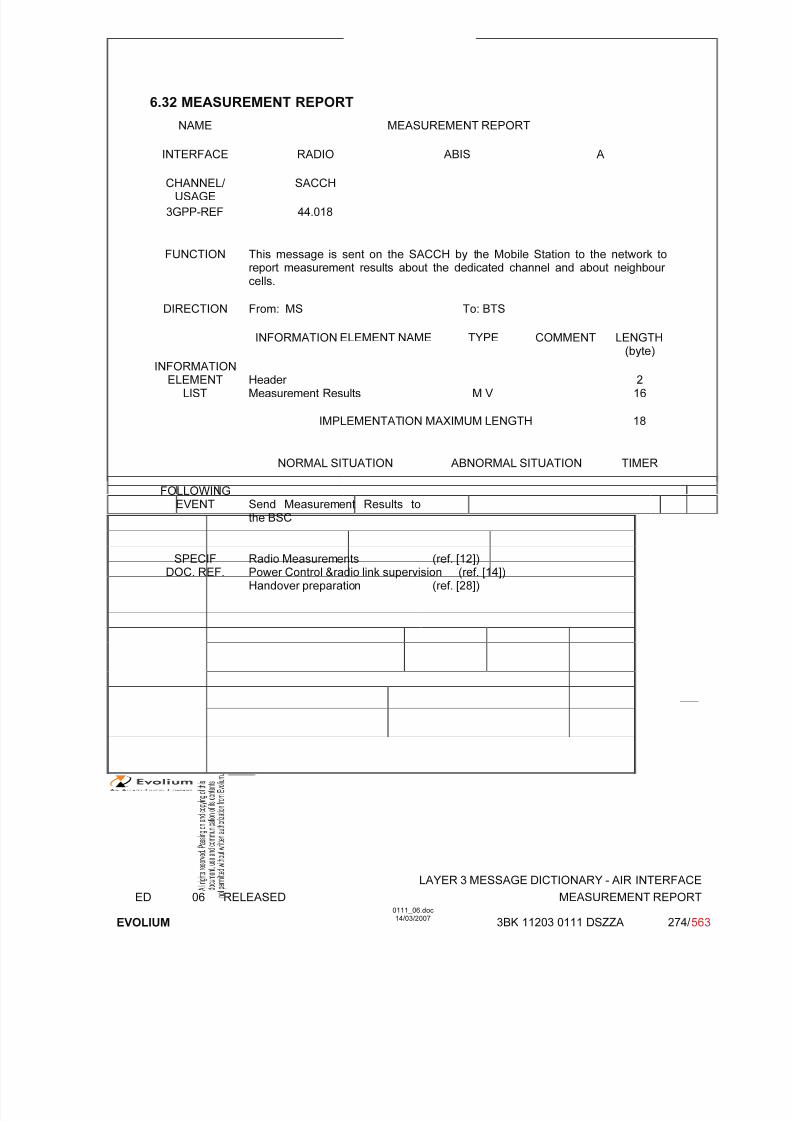
7/11/2019 1. Layer3 Air Interface Messages 0111_06
http://slidepdf.com/reader/full/1-layer3-air-interface-messages-011106 274/562
LAYER 3 MESSAGE DICTIONARY - AIR INTERFACE
ED 06 RELEASED MEASUREMENT REPORT
EVOLIUM
0111_06.doc14/03/2007
3BK 11203 0111 DSZZA 274/ 563
6.32 MEASUREMENT REPORT
NAME MEASUREMENT REPORT
INTERFACE RADIO ABIS A
CHANNEL/ USAGE
SACCH
3GPP-REF 44.018
FUNCTION This message is sent on the SACCH by the Mobile Station to the network toreport measurement results about the dedicated channel and about neighbour cells.
DIRECTION From: MS To: BTS
INFORMATION ELEMENT NAME TYPE COMMENT LENGTH(byte)
INFORMATIONELEMENT
LISTHeader Measurement Results M V
216
IMPLEMENTATION MAXIMUM LENGTH 18
NORMAL SITUATION ABNORMAL SITUATION TIMER
FOLLOWINGEVENT Send Measurement Results to
the BSC
SPECIFDOC. REF.
Radio Measurements (ref. [12])Power Control &radio link supervision (ref. [14])Handover preparation (ref. [28])
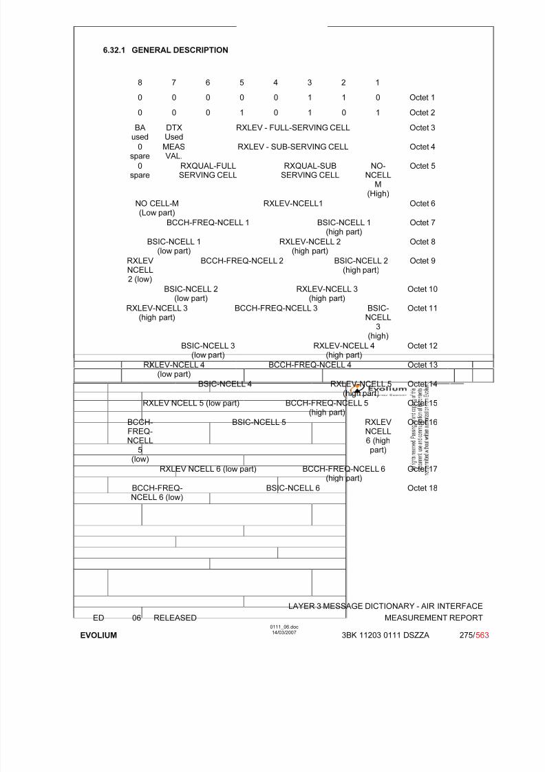
7/11/2019 1. Layer3 Air Interface Messages 0111_06
http://slidepdf.com/reader/full/1-layer3-air-interface-messages-011106 275/562
LAYER 3 MESSAGE DICTIONARY - AIR INTERFACE
ED 06 RELEASED MEASUREMENT REPORT
EVOLIUM
0111_06.doc14/03/2007
3BK 11203 0111 DSZZA 275/ 563
6.32.1 GENERAL DESCRIPTION
8 7 6 5 4 3 2 1
0 0 0 0 0 1 1 0 Octet 1
0 0 0 1 0 1 0 1 Octet 2
BAused
DTXUsed
RXLEV - FULL-SERVING CELL Octet 3
0spare
MEASVAL.
RXLEV - SUB-SERVING CELL Octet 4
0spare
RXQUAL-FULLSERVING CELL
RXQUAL-SUBSERVING CELL
NO-NCELL
M(High)
Octet 5
NO CELL-M(Low part)
RXLEV-NCELL1 Octet 6
BCCH-FREQ-NCELL 1 BSIC-NCELL 1(high part)
Octet 7
BSIC-NCELL 1(low part)
RXLEV-NCELL 2(high part)
Octet 8
RXLEV NCELL2 (low)
BCCH-FREQ-NCELL 2 BSIC-NCELL 2(high part)
Octet 9
BSIC-NCELL 2(low part)
RXLEV-NCELL 3(high part)
Octet 10
RXLEV-NCELL 3(high part)
BCCH-FREQ-NCELL 3 BSIC-NCELL
3(high)
Octet 11
BSIC-NCELL 3
(low part)
RXLEV-NCELL 4
(high part)
Octet 12
RXLEV-NCELL 4(low part)
BCCH-FREQ-NCELL 4 Octet 13
BSIC-NCELL 4 RXLEV-NCELL 5(high part)
Octet 14
RXLEV NCELL 5 (low part) BCCH-FREQ-NCELL 5(high part)
Octet 15
BCCH-FREQ-NCELL
5(low)
BSIC-NCELL 5 RXLEV NCELL6 (highpart)
Octet 16
RXLEV NCELL 6 (low part) BCCH-FREQ-NCELL 6
(high part)
Octet 17
BCCH-FREQ-NCELL 6 (low)
BSIC-NCELL 6 Octet 18

7/11/2019 1. Layer3 Air Interface Messages 0111_06
http://slidepdf.com/reader/full/1-layer3-air-interface-messages-011106 276/562
LAYER 3 MESSAGE DICTIONARY - AIR INTERFACE
ED 06 RELEASED MEASUREMENT REPORT
EVOLIUM
0111_06.doc14/03/2007
3BK 11203 0111 DSZZA 276/ 563
6.32.2 MEASUREMENT RESULTS
TYPE: M
DEFINITIONTo provide the results of the measurements made by the MS on the serving cell and the neighbour cells.
BIT DESCRIPTION
8 7 6 5 4 3 2 1
BAused
DTXUsed
RXLEV - FULL-SERVING CELL Octet 1
3G BAused
MEASVAL.
RXLEV - SUB-SERVING CELL Octet 2
0spare
RXQUAL-FULLSERVING CELL
RXQUAL-SUBSERVING CELL
NO-NCELL
M
(High)
Octet 3
NO CELL-M(Low part)
RXLEV-NCELL1 Octet 4
BCCH-FREQ-NCELL 1 BSIC-NCELL 1(high part)
Octet 5
BSIC-NCELL 1(low part)
RXLEV-NCELL 2(high part)
Octet 6
RXLEV NCELL2 (low)
BCCH-FREQ-NCELL 2 BSIC-NCELL 2(high part)
Octet 7
BSIC-NCELL 2(low part)
RXLEV-NCELL 3(high part)
Octet 8
RXLEV-NCELL 3(high part) BCCH-FREQ-NCELL 3 BSIC-NCELL3
(high)
Octet 9
BSIC-NCELL 3(low part)
RXLEV-NCELL 4(high part)
Octet 10
RXLEV-NCELL 4(low part)
BCCH-FREQ-NCELL 4 Octet 11
BSIC-NCELL 4 RXLEV-NCELL 5(high part)
Octet 12
RXLEV NCELL 5 (low part) BCCH-FREQ-NCELL 5(high part)
Octet 13
BCCH-
FREQ-NCELL
5(low)
BSIC-NCELL 5 RXLEV
NCELL6 (highpart)
Octet 14
RXLEV NCELL 6 (low part) BCCH-FREQ-NCELL 6(high part)
Octet 15
BCCH-FREQ-NCELL 6 (low)
BSIC-NCELL 6 Octet 16

7/11/2019 1. Layer3 Air Interface Messages 0111_06
http://slidepdf.com/reader/full/1-layer3-air-interface-messages-011106 277/562
LAYER 3 MESSAGE DICTIONARY - AIR INTERFACE
ED 06 RELEASED MEASUREMENT REPORT
EVOLIUM
0111_06.doc14/03/2007
3BK 11203 0111 DSZZA 277/ 563
SUB PARAMETER DEFINITION
BA-USED : The value of the BA-IND field of the neighbour cells descriptioninformation element defining the BCCH allocation used for the coding of BCCH-FREQ-NCELL fields. Range 0 to 1.
DTX USED : This bit indicates whether or not the MS used DTX during the previous
measurement period.0 DTX was not used1 DTX was used
RXLEV-FULL-SERVING CELL and RXLEV-SUB-SERVING CELL
Received signal strength on serving cell measured respectively on all slots and on a subsetof slots. It is coded as the binary representation of a value N (refer to GSM TS 05.08).The range is 0 to 63.
MEAS-VALID : This bit indicates if the measurement results for the dedicated channelare valid or not.0 the measurement results are valid.
1 the measurement results are not valid.
3G-BA-USED : The value of the 3G-BA-IND field of the neighbour cells description informationelement or elements defining the 3G Neighbour Cell list used for the coding of 3G BCCH-FREQ-NCELL fields. Range 0 to 1.
RXQUAL FULL-SERVING-CELLRXQUAL SUB-SERVING-CELL
Received signal quality on serving cell, measured respectively on all slots and on a subset of the slots. The range is 0 to 7.
NO-CELL M : Number of neighbouring cell measurements.
000 No Neighbour cell measurement result001 1 " " "010 2 " " "011 3 " " "100 4 " " "101 5 " " "110 6 " " "111 Neighbour cell information not available for serving cell
Note: If NO_CELL_M<6 the remaining RXLEV_NCELL i.e. BS_FREQ_NCELL-i and
BSIC_BCELL-i fields (NO_CELL_M<i≤6) shall be coded with a "0" in each bit.
RXLEV NCELL i :Range 0 to 63If the i’th neighbour cell is a GSM cell, this field is the received signal strength on the i'thneighbouring cell.If the i'th neighbour cell is a 3G cell, this field is the contents of the Ec/No. The foreseen rangeis 0..49 but an erroneous value (50..63) sent by a faulty MS is taken in account as received.
BCCH FREQ NCELL i :- For GSM cell, BCCH carrier of the i'th neighbouring cell. It is the representation of theposition of the i'th neighbouring cells BCCH carrier in the BCCH channel list. Range 0 to 31.- For 3G cell, this field will be coded as 31.
7/11/2019 1. Layer3 Air Interface Messages 0111_06
http://slidepdf.com/reader/full/1-layer3-air-interface-messages-011106 278/562
LAYER 3 MESSAGE DICTIONARY - AIR INTERFACE
ED 06 RELEASED MEASUREMENT REPORT
EVOLIUM
0111_06.doc14/03/2007
3BK 11203 0111 DSZZA 278/ 563
BSIC NCELL i :Range 0 to 63.For GSM cell, this field is Base Station identity code for the i'th neighbouring cell.For 3G cell, this field carries the index of the i'th 3G neighbour cell in the 3G neighbour celllist.
PARAMETER ORIGIN - ACTION ON PARAMETER
This information is used by the BSC to perform pre-processing, power control and handover evaluation.
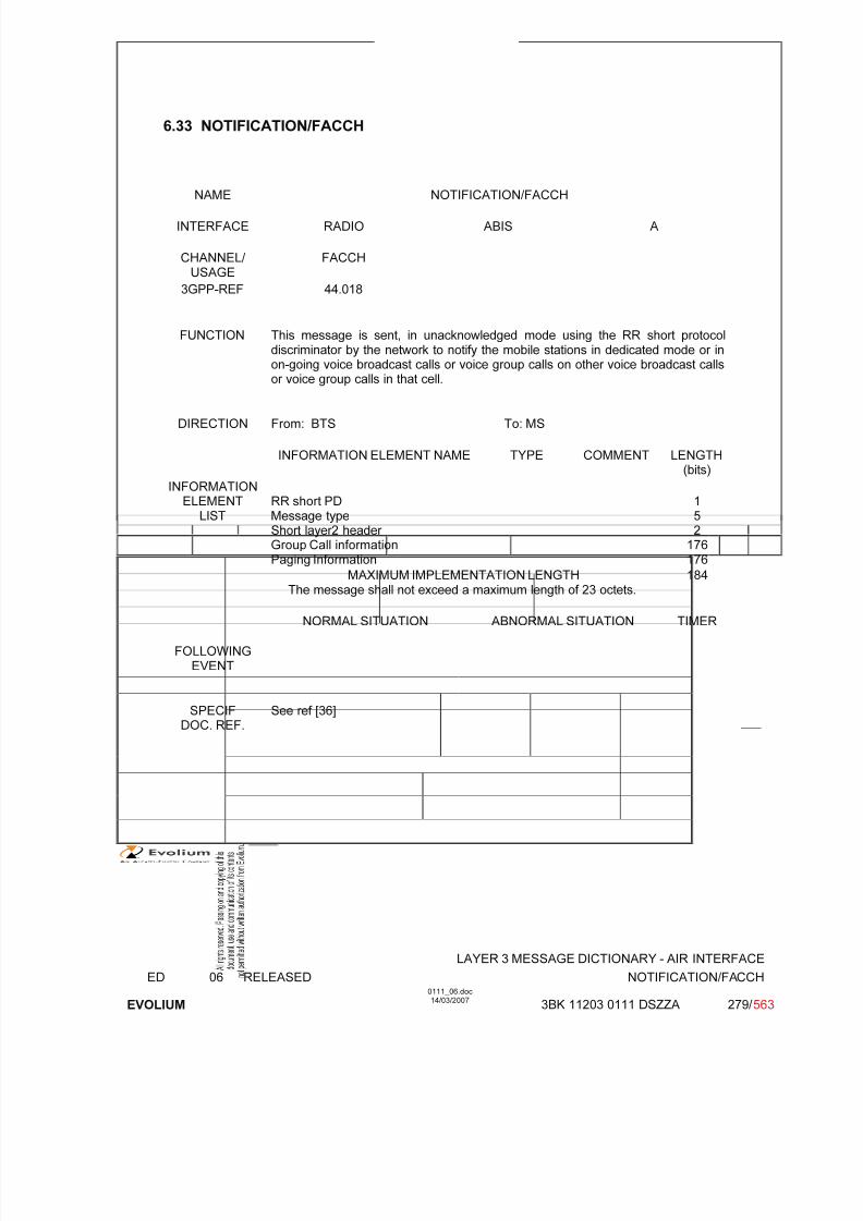
7/11/2019 1. Layer3 Air Interface Messages 0111_06
http://slidepdf.com/reader/full/1-layer3-air-interface-messages-011106 279/562
LAYER 3 MESSAGE DICTIONARY - AIR INTERFACE
ED 06 RELEASED NOTIFICATION/FACCH
EVOLIUM
0111_06.doc14/03/2007
3BK 11203 0111 DSZZA 279/ 563
6.33 NOTIFICATION/FACCH
NAME NOTIFICATION/FACCH
INTERFACE RADIO ABIS A
CHANNEL/ USAGE
FACCH
3GPP-REF 44.018
FUNCTION This message is sent, in unacknowledged mode using the RR short protocoldiscriminator by the network to notify the mobile stations in dedicated mode or inon-going voice broadcast calls or voice group calls on other voice broadcast calls
or voice group calls in that cell.
DIRECTION From: BTS To: MS
INFORMATION ELEMENT NAME TYPE COMMENT LENGTH(bits)
INFORMATIONELEMENT
LISTRR short PDMessage typeShort layer2 header Group Call information
Paging Information
152
176
176MAXIMUM IMPLEMENTATION LENGTH
The message shall not exceed a maximum length of 23 octets.184
NORMAL SITUATION ABNORMAL SITUATION TIMER
FOLLOWINGEVENT
SPECIFDOC. REF.
See ref [36]

7/11/2019 1. Layer3 Air Interface Messages 0111_06
http://slidepdf.com/reader/full/1-layer3-air-interface-messages-011106 280/562
LAYER 3 MESSAGE DICTIONARY - AIR INTERFACE
ED 06 RELEASED NOTIFICATION/FACCH
EVOLIUM
0111_06.doc14/03/2007
3BK 11203 0111 DSZZA 280/ 563
6.33.1 GENERAL DESCRIPTION
<NOTIFICATION FACCH> ::= <RR short PD : bit><message type : bit(5)>
<short layer 2 header : bit(2)>
{0 <Group Call information>|1 <Paging Information>}<spare padding> ;
<Group Call information> ::= <Group Call Reference : bit(36)>{0|1 <Group Channel Description>} ;
<Group Channel Description> : := <Channel Description : bit(24)>{0 -- Non hopping case|1 {0 <Mobile Allocation : <bit string>>|1 <Frequency Short List : bit(64)>}} ;
<Paging Information> ::= <mobile identity : <bit string>><channel first: bit(2)>
{0|1 <eMLPP priority : bit(3)>} ;
<bit string> ::= null | bit <bit string> ;
6.33.2 NOTIFICATION/FACCH with Group call Information
BIT DESCRIPTION
Notification/FACCH without Group Channel Description
8 7 6 5 4 3 2 1
0(header) RRshortPD
Message type Short layer 2header
1 0
2
3 Group call Reference
4
5 0 Sparepaddin
g1
Sparepaddin
g1
6 Sparepaddin
g0
Sparepaddin
g0
Sparepaddin
g1
Sparepaddin
g0
Sparepaddin
g1
Sparepaddin
g0
Sparepaddin
g1
Sparepaddin
g1
….. …….

7/11/2019 1. Layer3 Air Interface Messages 0111_06
http://slidepdf.com/reader/full/1-layer3-air-interface-messages-011106 281/562
LAYER 3 MESSAGE DICTIONARY - AIR INTERFACE
ED 06 RELEASED NOTIFICATION/FACCH
EVOLIUM
0111_06.doc14/03/2007
3BK 11203 0111 DSZZA 281/ 563
22 Sparepaddin
g0
Sparepaddin
g0
Sparepaddin
g1
Sparepaddin
g0
Sparepaddin
g1
Sparepaddin
g0
Sparepaddin
g1
Sparepaddin
g1
Notification/FACCH with Group Channel Description
Non hopping case
8 7 6 5 4 3 2 1
0(header) RRshort
PD
Message type Short layer 2header
1 0
2
3 Group call Reference
4
5 1 Channel typeand TDMA offset
6 Channel type and TDMAoffset con’t
TN TSC
7 TSC
Con’t
H
0
Spare
0
Spare
0
ARFCN (Hpart)
8 A R F C N (low part) 0 Sparepaddin
g1
9 Sparepaddin
g0
Sparepaddin
g0
Sparepaddin
g1
Sparepaddin
g0
Sparepaddin
g1
Sparepaddin
g0
Sparepaddin
g1
Sparepaddin
g1
….. …….
22 Sparepaddin
g0
Sparepaddin
g0
Sparepaddin
g1
Sparepaddin
g0
Sparepaddin
g1
Sparepaddin
g0
Sparepaddin
g1
Sparepaddin
g1
Notification/FACCH with Group Channel Description
Hopping case with mobile allocation
8 7 6 5 4 3 2 1

7/11/2019 1. Layer3 Air Interface Messages 0111_06
http://slidepdf.com/reader/full/1-layer3-air-interface-messages-011106 282/562
LAYER 3 MESSAGE DICTIONARY - AIR INTERFACE
ED 06 RELEASED NOTIFICATION/FACCH
EVOLIUM
0111_06.doc14/03/2007
3BK 11203 0111 DSZZA 282/ 563
0(header) RRshortPD
Message type Short layer 2header
1 0
2
3 Group Call Reference
4
5 1 Channel typeand TDMA offset
6 Channel type and TDMAoffset con’t
TN TSC
7 TSCCon’t
H1
(High part) MAIO (low part)
8 HSN 1 0
9 Length of Mobile alloc. Contents =n (n < 8) See note
10 MA
C8n
MA
C8n-1
MA
C8n-7
….. ……..
10 +(n-1) MAC8
MAC1
10+ n Sparepaddin
g0
Sparepaddin
g0
Sparepaddin
g1
Sparepaddin
g0
Sparepaddin
g1
Sparepaddin
g0
Sparepaddin
g1
Sparepaddin
g1
…….
22 Sparepadding0
Sparepadding0
Sparepadding1
Sparepadding0
Sparepadding1
Sparepadding0
Sparepadding1
Sparepadding1
Note: According to ref.[38], If NF mod 8 <> 0 then bits NF (NF: Number of Frequencies defined by theCA (“Cell Channel Description” in the System Information Type 1 message) to 8n in octet 10must be coded with a "0" in each. For example, if NF = 12, then Mobile Allocation is coded asfollow:
9 Length of Mobile alloc. Contents = 2
10 0 0 0 0 MAC
12
MAC
11
MAC
10
MAC
911 MAC
8MAC
7MAC
6MAC
5MAC
4MAC
3MAC
2MAC
1
Notification/FACCH carries Group Call Information with Group Channel Description
Hopping case with frequency short list
8 7 6 5 4 3 2 1

7/11/2019 1. Layer3 Air Interface Messages 0111_06
http://slidepdf.com/reader/full/1-layer3-air-interface-messages-011106 283/562
LAYER 3 MESSAGE DICTIONARY - AIR INTERFACE
ED 06 RELEASED NOTIFICATION/FACCH
EVOLIUM
0111_06.doc14/03/2007
3BK 11203 0111 DSZZA 283/ 563
0 (header) RRshortPD
Message type Short layer 2header
1 0
2
3 Group Call Reference
4
5 1 Channel typeand TDMA offset
6 Channel type and TDMAoffset con’t
TN TSC
7 TSCCon’t
H1
(High part) MAIO (low part)
8 HSN 1 1
9
10
11
12 Frequency short list
13
14
15
16
17 Sparepaddin
g0
Sparepaddin
g0
Sparepaddin
g1
Sparepaddin
g0
Sparepaddin
g1
Sparepaddin
g0
Sparepaddin
g1
Sparepaddin
g1
….. …….
22 Sparepaddin
g0
Sparepaddin
g0
Sparepaddin
g1
Sparepaddin
g0
Sparepaddin
g1
Sparepaddin
g0
Sparepaddin
g1
Sparepaddin
g1
6.33.3 PARAMETER DESCRIPTION
6.33.3.1 Group Call Reference
In the message notification/facch the group call reference only contains octets n-n+4 and bits 5 to 8 of octet n+4.The description is given in a byte aligned format for readability.
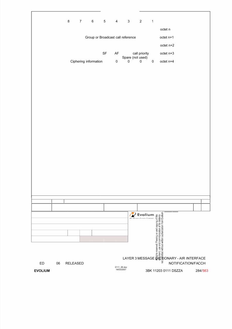
7/11/2019 1. Layer3 Air Interface Messages 0111_06
http://slidepdf.com/reader/full/1-layer3-air-interface-messages-011106 284/562
LAYER 3 MESSAGE DICTIONARY - AIR INTERFACE
ED 06 RELEASED NOTIFICATION/FACCH
EVOLIUM
0111_06.doc14/03/2007
3BK 11203 0111 DSZZA 284/ 563
8 7 6 5 4 3 2 1
octet n
Group or Broadcast call reference octet n+1
octet n+2
SF AF call priority octet n+3
Spare (not used)Ciphering information 0 0 0 0 octet n+4

7/11/2019 1. Layer3 Air Interface Messages 0111_06
http://slidepdf.com/reader/full/1-layer3-air-interface-messages-011106 285/562
LAYER 3 MESSAGE DICTIONARY - AIR INTERFACE
ED 06 RELEASED NOTIFICATION/FACCH
EVOLIUM
0111_06.doc14/03/2007
3BK 11203 0111 DSZZA 285/ 563
Group or Broadcast call reference :
A bit(27) string identifying the voice group call in case of VGCS.
SF Service flag
0 VBS (broadcast call reference) Not used1 VGCS (group call reference)
AF Acknowledgement flag, network to MS direction:
0 acknowledgement is not required1 acknowledgement is required Not used
Call prioritySet to the value received in the VGCS assignement request message
0 0 0 no priority applied0 0 1 call priority level 40 1 0 call priority level 30 1 1 call priority level 21 0 0 call priority level 11 0 1 call priority level 01 1 0 call priority level B1 1 1 call priority level A
Ciphering information
0 0 0 0 no ciphering
0 0 0 1 ciphering with cipher key number 1 Not used0 0 1 0 ciphering with cipher key number 2 Not used0 0 1 1 ciphering with cipher key number 3 Not used0 1 0 0 ciphering with cipher key number 4 Not used0 1 0 1 ciphering with cipher key number 5 Not used0 1 1 0 ciphering with cipher key number 6 Not used0 1 1 1 ciphering with cipher key number 7 Not used1 0 0 0 ciphering with cipher key number 8 Not used1 0 0 1 ciphering with cipher key number 9 Not used1 0 1 0 ciphering with cipher key number A Not used1 0 1 1 ciphering with cipher key number B Not used1 1 0 0 ciphering with cipher key number C Not used1 1 0 1 ciphering with cipher key number D Not used
1 1 1 0 ciphering with cipher key number E Not used1 1 1 1 ciphering with cipher key number F Not used
6.33.3.2 Group Channel Description
The <Group Channel Description> field is optionally present. When present only the Channeldescription is provided in the case of non hopping channels. In the case where the channel is hoppingthen either a mobile allocation or a frequency short list is provided.

7/11/2019 1. Layer3 Air Interface Messages 0111_06
http://slidepdf.com/reader/full/1-layer3-air-interface-messages-011106 286/562
LAYER 3 MESSAGE DICTIONARY - AIR INTERFACE
ED 06 RELEASED NOTIFICATION/FACCH
EVOLIUM
0111_06.doc14/03/2007
3BK 11203 0111 DSZZA 286/ 563
6.33.3.2.1 Channel description
SUB PARAMETER DEFINITION
Octet 1
Channel type and TDMA offset.
Bits 8 7 6 5 40 0 0 0 1 TCH/F + ACCHs0 0 0 1 T TCH/H + ACCHs0 0 1 T T SDCCH/4 + SACCH/C4 or CBCH (SDCCH/4) (not used)0 1 T T T SDCCH/8 + SACCH/C8 or CBCH (SDCCH/8) (not used)all other values are reserved.
T bit indicates the Subchannel Number.
TN : Time slot (0 to 7)
Octets 2 and 3:
TSC : Training Sequence Code (0 to 7)
H : "0" Single RF channel"1" RF hopping channel
Channel selector:
H = "0": The channel selector field consists of the absolute RF channel number.Bits 4 3
0 0 spare
ARFCN:Octet 2 Bits 2,1 High part of ARFCNOctet 3 Bits 8 to 1 ARFCN low part
The ARFCN is coded as the binary representation of the absolute RF channelNumber.
Range 0 to 1023.
H = "1": The channel selector field consists of the mobile allocation index offset, MAIO, and thehopping sequence number, HSN.
MAIO:Octet 2 Bits 4 to 1 High partOctet 3 Bits 8 to 7 Low part
HSN (Octet 3, Bits 1 to 6)Value 0 to 63.
The HSN field is coded as the binary representation of the hopping sequence number.
6.33.3.2.2 Mobile allocation
DEFINITION
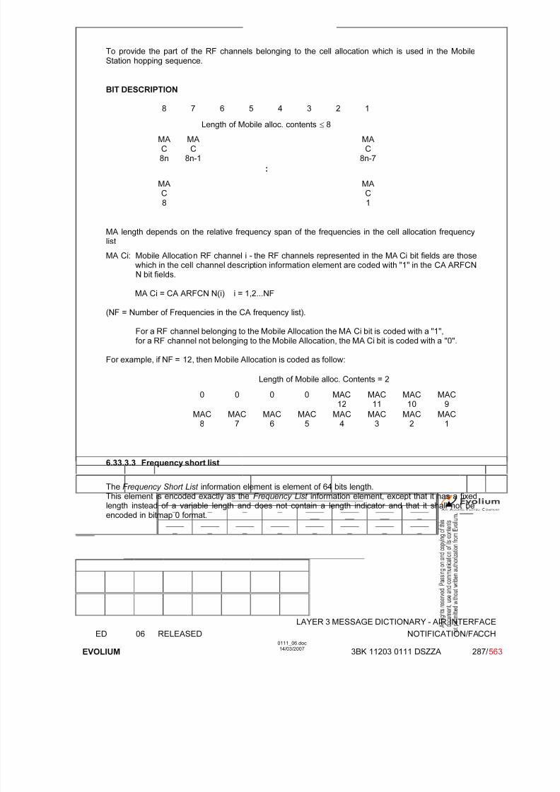
7/11/2019 1. Layer3 Air Interface Messages 0111_06
http://slidepdf.com/reader/full/1-layer3-air-interface-messages-011106 287/562
LAYER 3 MESSAGE DICTIONARY - AIR INTERFACE
ED 06 RELEASED NOTIFICATION/FACCH
EVOLIUM
0111_06.doc14/03/2007
3BK 11203 0111 DSZZA 287/ 563
To provide the part of the RF channels belonging to the cell allocation which is used in the MobileStation hopping sequence.
BIT DESCRIPTION
8 7 6 5 4 3 2 1
Length of Mobile alloc. contents ≤ 8
MAC8n
MAC
8n-1
MAC
8n-7
:
MAC8
MAC1
MA length depends on the relative frequency span of the frequencies in the cell allocation frequency
listMA Ci: Mobile Allocation RF channel i - the RF channels represented in the MA Ci bit fields are those
which in the cell channel description information element are coded with "1" in the CA ARFCNN bit fields.
MA Ci = CA ARFCN N(i) i = 1,2...NF
(NF = Number of Frequencies in the CA frequency list).
For a RF channel belonging to the Mobile Allocation the MA Ci bit is coded with a "1",for a RF channel not belonging to the Mobile Allocation, the MA Ci bit is coded with a "0".
For example, if NF = 12, then Mobile Allocation is coded as follow:
Length of Mobile alloc. Contents = 2
0 0 0 0 MAC12
MAC11
MAC10
MAC9
MAC8
MAC7
MAC6
MAC5
MAC4
MAC3
MAC2
MAC1
6.33.3.3 Frequency short list
The Frequency Short List information element is element of 64 bits length.This element is encoded exactly as the Frequency List information element, except that it has a fixedlength instead of a variable length and does not contain a length indicator and that it shall not beencoded in bitmap 0 format.

7/11/2019 1. Layer3 Air Interface Messages 0111_06
http://slidepdf.com/reader/full/1-layer3-air-interface-messages-011106 288/562
LAYER 3 MESSAGE DICTIONARY - AIR INTERFACE
ED 06 RELEASED NOTIFICATION/FACCH
EVOLIUM
0111_06.doc14/03/2007
3BK 11203 0111 DSZZA 288/ 563
DEFINITIONTo provide the absolute radio frequency channel numbers used in a cell (fixed lengthfrequency list).
BIT DESCRIPTION
Range 1024 format
8 7 6 5 4 3 2 1
0 0 0 0 0 0 1 0 1
1 0FORMAT-ID
0 0 0FORM-
ID
F0 W(1)(high part)
2
W(1) (low part) 3
:
W(2) to W(3) are on 9 bits, when presentW(4) to W(7) are on 8 bits, when presentW(8) to W(15) are on 7 bits, when presentW(16) to W(31) are on 6 bits, when presentW(2k) to W((2k+1) - 1) are on 10-k bits
Range 512 format supported
8 7 6 5 4 3 2 1
0 0 0 0 0 0 1 0 1
1 0FORMAT-ID
0 0 1 0 0FORMAT-ID(continued)
ORIG-ARFCN
2
ORIG-ARFCN (middle part) 3
ORIG-ARFCN
(low)
W(1) (high part) 4
W(1) (low part) W(2) (high part) 5
:
W(2) to W(3) are on 8 bits, when presentW(4) to W(7) are on 7 bits, when presentW(8) to W(15) are on 6 bits, when presentW(16) to W(31) are on 5 bits, when presentW(2k) to W((2k+1) - 1) are on 9-k bits
Range 256 format supported
8 7 6 5 4 3 2 1
0 0 0 0 0 0 1 0 1

7/11/2019 1. Layer3 Air Interface Messages 0111_06
http://slidepdf.com/reader/full/1-layer3-air-interface-messages-011106 289/562
LAYER 3 MESSAGE DICTIONARY - AIR INTERFACE
ED 06 RELEASED NOTIFICATION/FACCH
EVOLIUM
0111_06.doc14/03/2007
3BK 11203 0111 DSZZA 289/ 563
1 0FORMAT-ID
0 0 1 0 1FORMAT-ID(continued)
ORIG-ARFCN
2
ORIG-ARFCN (middle part) 3
ORIG-ARFCN
(low)
W(1) (high part) 4
W(1)(lowpart)
W(2) 5
:
W(2) to W(3) are on 7 bits, when presentW(4) to W(7) are on 6 bits, when presentW(8) to W(15) are on 5 bits, when presentW(16) to W(31) are on 4 bits, when presentW(2k) to W((2k+1) - 1) are on 8-k bits
Range 128 format supported
8 7 6 5 4 3 2 1
0 0 0 0 0 0 1 0 1
1 0FORMAT-ID
0 0 1 1 0FORMAT-ID(continued)
ORIG-ARFCN
2
ORIG-ARFCN (middle part) 3
ORIG-ARFCN
(low)
W(1) 4
:
W(2) to W(3) are on 6 bits, when presentW(4) to W(7) are on 5 bits, when presentW(8) to W(15) are on 4 bits, when presentW(16) to W(31) are on 3 bits, when presentW(2k) to W((2k+1) - 1) are on 7-k bits

7/11/2019 1. Layer3 Air Interface Messages 0111_06
http://slidepdf.com/reader/full/1-layer3-air-interface-messages-011106 290/562
LAYER 3 MESSAGE DICTIONARY - AIR INTERFACE
ED 06 RELEASED NOTIFICATION/FACCH
EVOLIUM
0111_06.doc14/03/2007
3BK 11203 0111 DSZZA 290/ 563
Variable bit map format supported
8 7 6 5 4 3 2 1
0 0 0 0 0 0 1 0 1
1 0FORMAT-ID
0 0 1 1 1FORMAT-ID
(continued)
ORIG-ARFCN
high
2
ORIG-ARFCN (middle part) 3
ORIG-ARFCN
(low)
RRFCN1
RRFCN2
RRFCN3
RRFCN4
RRFCN5
RRFCN6
RRFCN7
4
: :
RRFCN31
RRFCN33
RRFCN34
RRFCN35
RRFCN36
RRFCN37
RRFCN38
RRFCN39
8
Bits 5 and 6 are spare bits in octet 2.
SUB PARAMETER DEFINITION
FORMAT-ID : Format identifier.
F0 : Frequency 0 indicator. Coded 0 if ARFCN 0 is not a member of the set. Coded 1 if ARFCN 0 is a member of the set.
ORIG-ARFCN : This field encodes the ARFCN of one frequency belonging to the set. This value isalso used as the origin of the bit map to generate all the other frequencies.
RRFCN N : Relative radio frequency channel number N- For an RF channel with ARFCN = (ORIG-ARFCN + N) mod 1024 belonging to the set,
then RRFCN N bit is coded as '1'.-
For an RF channel with ARFCN = (ORIG-ARFCN + N) mod 1024 not belonging to the set,then RRFCN N bit is coded as '0'.
W : Each non null W(k) allows to compute, together with some previous W(i) the ARFCNF(k) of a frequency in the set (see 3GPP TS 44.018 for computation formulas).
PARAMETER ORIGIN - ACTION ON PARAMETER
ORIG-ARFCN, RRFCN N : Values stored in BSC and updated according to systemreconfigurations.
PARAMETER ORIGIN - ACTION ON PARAMETER
PARAMETER ORIGIN - ACTION ON PARAMETER
This parameter is transparent for the BTS when received.
At the BSC site, the BSC has to provide the following information:
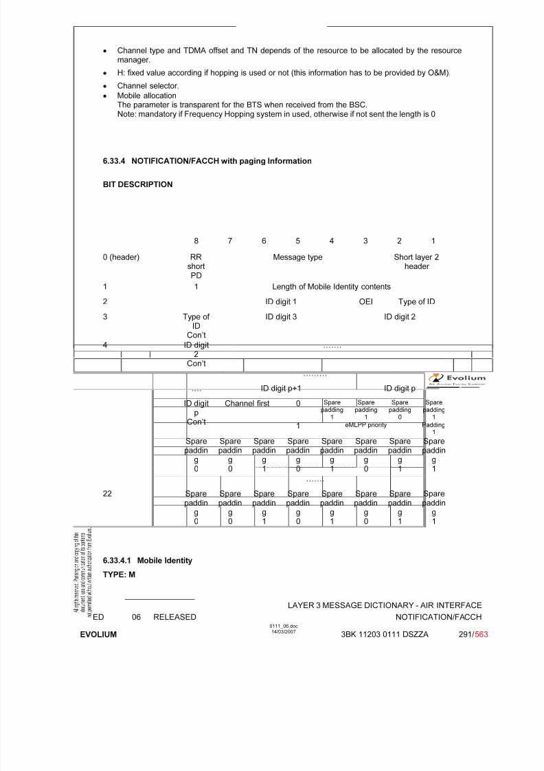
7/11/2019 1. Layer3 Air Interface Messages 0111_06
http://slidepdf.com/reader/full/1-layer3-air-interface-messages-011106 291/562
LAYER 3 MESSAGE DICTIONARY - AIR INTERFACE
ED 06 RELEASED NOTIFICATION/FACCH
EVOLIUM
0111_06.doc14/03/2007
3BK 11203 0111 DSZZA 291/ 563
• Channel type and TDMA offset and TN depends of the resource to be allocated by the resourcemanager.
• H: fixed value according if hopping is used or not (this information has to be provided by O&M).
• Channel selector.
• Mobile allocationThe parameter is transparent for the BTS when received from the BSC.Note: mandatory if Frequency Hopping system in used, otherwise if not sent the length is 0
6.33.4 NOTIFICATION/FACCH with paging Information
BIT DESCRIPTION
8 7 6 5 4 3 2 1
0 (header) RRshortPD
Message type Short layer 2header
1 1 Length of Mobile Identity contents
2 ID digit 1 OEI Type of ID
3 Type of ID
Con’t
ID digit 3 ID digit 2
4 ID digit
2Con’t
…….
………
…. ID digit p+1 ID digit p
0 Spare
padding1
Spare
padding1
Spare
padding0
Spare
padding1
ID digitp
Con’t
Channel first
1 eMLPP priority Padding1
Sparepaddin
g0
Sparepaddin
g0
Sparepaddin
g1
Sparepaddin
g0
Sparepaddin
g1
Sparepaddin
g0
Sparepaddin
g1
Sparepaddin
g1
…….
22 Sparepaddin
g0
Sparepaddin
g0
Sparepaddin
g1
Sparepaddin
g0
Sparepaddin
g1
Sparepaddin
g0
Sparepaddin
g1
Sparepaddin
g1
6.33.4.1 Mobile Identity
TYPE: M
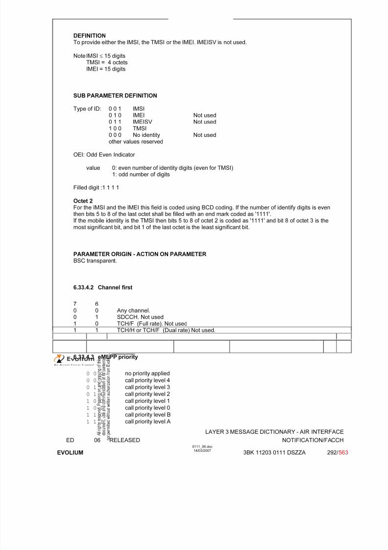
7/11/2019 1. Layer3 Air Interface Messages 0111_06
http://slidepdf.com/reader/full/1-layer3-air-interface-messages-011106 292/562
LAYER 3 MESSAGE DICTIONARY - AIR INTERFACE
ED 06 RELEASED NOTIFICATION/FACCH
EVOLIUM
0111_06.doc14/03/2007
3BK 11203 0111 DSZZA 292/ 563
DEFINITIONTo provide either the IMSI, the TMSI or the IMEI. IMEISV is not used.
Note IMSI ≤ 15 digitsTMSI = 4 octetsIMEI = 15 digits
SUB PARAMETER DEFINITION
Type of ID: 0 0 1 IMSI0 1 0 IMEI Not used0 1 1 IMEISV Not used1 0 0 TMSI0 0 0 No identity Not usedother values reserved
OEI: Odd Even Indicator
value 0: even number of identity digits (even for TMSI)1: odd number of digits
Filled digit :1 1 1 1
Octet 2 For the IMSI and the IMEI this field is coded using BCD coding. If the number of identify digits is eventhen bits 5 to 8 of the last octet shall be filled with an end mark coded as '1111'.If the mobile identity is the TMSI then bits 5 to 8 of octet 2 is coded as '1111' and bit 8 of octet 3 is themost significant bit, and bit 1 of the last octet is the least significant bit.
PARAMETER ORIGIN - ACTION ON PARAMETERBSC transparent.
6.33.4.2 Channel first
7 60 0 Any channel.0 1 SDCCH. Not used1 0 TCH/F (Full rate). Not used1 1 TCH/H or TCH/F (Dual rate) Not used.
6.33.4.3 eMLPP priority
0 0 0 no priority applied
0 0 1 call priority level 4
0 1 0 call priority level 3
0 1 1 call priority level 2
1 0 0 call priority level 1
1 0 1 call priority level 0
1 1 0 call priority level B
1 1 1 call priority level A
7/11/2019 1. Layer3 Air Interface Messages 0111_06
http://slidepdf.com/reader/full/1-layer3-air-interface-messages-011106 293/562
LAYER 3 MESSAGE DICTIONARY - AIR INTERFACE
ED 06 RELEASED NOTIFICATION/FACCH
EVOLIUM
0111_06.doc14/03/2007
3BK 11203 0111 DSZZA 293/ 563
PARAMETER ORIGIN - ACTION ON PARAMETER

7/11/2019 1. Layer3 Air Interface Messages 0111_06
http://slidepdf.com/reader/full/1-layer3-air-interface-messages-011106 294/562
LAYER 3 MESSAGE DICTIONARY - AIR INTERFACE
ED 06 RELEASED NOTIFICATION/NCH
EVOLIUM
0111_06.doc14/03/2007
3BK 11203 0111 DSZZA 294/ 563
6.34 NOTIFICATION/NCH
NAME NOTIFICATION/NCH
INTERFACE RADIO ABIS A
CHANNEL/ USAGE
NCH
3GPP-REF 44.018
FUNCTION This message is sent on the NCH by the network to notify mobile stations of VBSor VGCS calls in the current cell. The VBS or VGCS calls are identified by their broadcast call reference or group call reference, respectively. For eachreference, the corresponding VBS or VGCS call channel may be indicated.
DIRECTION From : BTS To : MS
INFORMATION ELEMENT NAME TYPE COMMENT LENGTH(byte)
INFORMATIONELEMENT
LISTL2 Pseudo LengthHeader NT/N Rest Octets
M V M V M V
1220
IMPLEMENTATION MAXIMUM LENGTH 23
NORMAL SITUATION ABNORMAL SITUATION TIMER
FOLLOWINGEVENT
SPECIFDOC. REF.
See ref [36]

7/11/2019 1. Layer3 Air Interface Messages 0111_06
http://slidepdf.com/reader/full/1-layer3-air-interface-messages-011106 295/562
LAYER 3 MESSAGE DICTIONARY - AIR INTERFACE
ED 06 RELEASED NOTIFICATION/NCH
EVOLIUM
0111_06.doc14/03/2007
3BK 11203 0111 DSZZA 295/ 563
6.34.1 GENERAL DESCRIPTION
8 7 6 5 4 3 2 1
L2 Pseudo length 0 0 0 0 0 0 0 10 0 0 0 0 1 1 0
0 0 1 0 0 0 0 0
NT/N Rest Octets See CSN.1 description in 6.34.1.1
6.34.1.1 NTN Rest Octets description
NT/N Rest Octets ::={0 I 1<NLN(NCH) : bit (2)>}<list of Group Call NCH information><Spare padding>;
<List of Group Call NCH information> ::=0 | 1 <Group Call information> <List of Group Call NCH information> ;
<Group Call information> ::= <Group Call Reference : bit(36)>{0|1 <Group Channel Description>} ;
<Group Channel Description> : := <Channel Description : bit(24)>{0 -- Non hopping case|1 {0 <Mobile Allocation : <bit string>>
|1 <Frequency Short List : bit(64)>}} ;
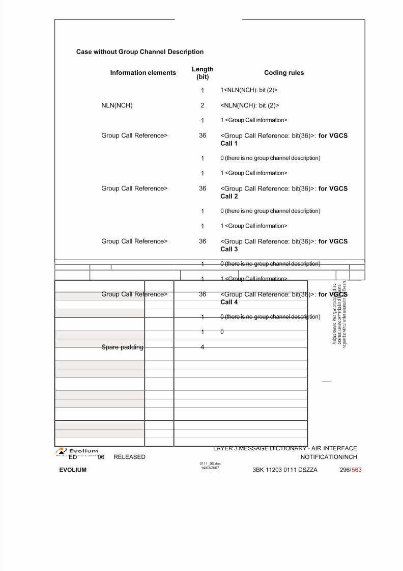
7/11/2019 1. Layer3 Air Interface Messages 0111_06
http://slidepdf.com/reader/full/1-layer3-air-interface-messages-011106 296/562
LAYER 3 MESSAGE DICTIONARY - AIR INTERFACE
ED 06 RELEASED NOTIFICATION/NCH
EVOLIUM
0111_06.doc14/03/2007
3BK 11203 0111 DSZZA 296/ 563
Case without Group Channel Description
Information elements Length
(bit)Coding rules
1 1<NLN(NCH): bit (2)>
NLN(NCH) 2 <NLN(NCH): bit (2)>
1 1 <Group Call information>
Group Call Reference> 36 <Group Call Reference: bit(36)>: for VGCSCall 1
1 0 (there is no group channel description)
1 1 <Group Call information>
Group Call Reference> 36 <Group Call Reference: bit(36)>: for VGCSCall 2
1 0 (there is no group channel description)
1 1 <Group Call information>
Group Call Reference> 36 <Group Call Reference: bit(36)>: for VGCSCall 3
1 0 (there is no group channel description)
1 1 <Group Call information>
Group Call Reference> 36 <Group Call Reference: bit(36)>: for VGCSCall 4
1 0 (there is no group channel description)
1 0
Spare padding 4

7/11/2019 1. Layer3 Air Interface Messages 0111_06
http://slidepdf.com/reader/full/1-layer3-air-interface-messages-011106 297/562
LAYER 3 MESSAGE DICTIONARY - AIR INTERFACE
ED 06 RELEASED NOTIFICATION/NCH
EVOLIUM
0111_06.doc14/03/2007
3BK 11203 0111 DSZZA 297/ 563
Case with Group Channel Description and without Frequency Hopping
Information elements Length
(bit)Coding rules
1 1<NLN(NCH): bit (2)>
NLN(NCH) 2 <NLN(NCH): bit (2)>
1 1 <Group Call information>
Group Call Reference> 36 <Group Call Reference: bit(36)>: for VGCSCall 1
1 1 <Group Channel Description>, for VGCS Call 1
Channel Description 24 <Channel Description : bit(24)>, for VGCSCall 1
1 0 -- Non hopping case, for VGCS Call 1
1 1 <Group Call information>
Group Call Reference> 36 <Group Call Reference: bit(36)>: for VGCSCall 2
1 1 <Group Channel Description>, for VGCS Call 2
Channel Description 24 <Channel Description : bit(24)>, for VGCSCall 2
1 0 -- Non hopping case, for VGCS Call 2
1 0
Spare padding 30

7/11/2019 1. Layer3 Air Interface Messages 0111_06
http://slidepdf.com/reader/full/1-layer3-air-interface-messages-011106 298/562
LAYER 3 MESSAGE DICTIONARY - AIR INTERFACE
ED 06 RELEASED NOTIFICATION/NCH
EVOLIUM
0111_06.doc14/03/2007
3BK 11203 0111 DSZZA 298/ 563
Case with Group Channel Description -Mixed Frequency Hopping and Non hopping
VGCS Call 1: Frequency Hopping with Mobile Allocation (number of Radio frequencies in thecell equal to 12, see section 6.33.3.2.2 );
VGCS Call 2: Non-hopping.
Informationelements
Length(bit)
Coding rules
1 1<NLN(NCH): bit (2)>
NLN(NCH) 2 <NLN(NCH): bit (2)>
1 1 <Group Call information>
Group Call
Reference>
36 <Group Call Reference: bit(36)>: for VGCS Call 1
1 1 <Group Channel Description>, for VGCS Call 1
Channel Description 24 <Channel Description : bit(24)>, for VGCS Call 1
1 1 -- hopping case, for VGCS Call 1
1 0 <Mobile Allocation : <bit string>>, for VGCS Call 1
Mobile Allocation 24
1 1 <Group Call information>
Group CallReference>
36 <Group Call Reference: bit(36)>: for VGCS Call 2
1 1 <Group Channel Description>, for VGCS Call 2
Channel Description 24 <Channel Description : bit(24)>, for VGCS Call 2
1 0 -- Non hopping case, for VGCS Call 2
1 0
Spare padding 5
6.34.2 PARAMETER DESCRIPTION
6.34.2.1 Notification List Number
NLN(NCH) : This field gives the NLN value to be used .
7/11/2019 1. Layer3 Air Interface Messages 0111_06
http://slidepdf.com/reader/full/1-layer3-air-interface-messages-011106 299/562
LAYER 3 MESSAGE DICTIONARY - AIR INTERFACE
ED 06 RELEASED NOTIFICATION/NCH
EVOLIUM
0111_06.doc14/03/2007
3BK 11203 0111 DSZZA 299/ 563
6.34.2.2 Group Call Reference
See 6.33.3.1
6.34.2.3 Group channel description
6.34.2.3.1 Channel description
See 6.33.3.2.1
6.34.2.3.2 Mobile Allocation
See 6.33.3.2.2
6.34.2.3.3 Frequency short list
See 6.33.3.3

7/11/2019 1. Layer3 Air Interface Messages 0111_06
http://slidepdf.com/reader/full/1-layer3-air-interface-messages-011106 300/562
LAYER 3 MESSAGE DICTIONARY - AIR INTERFACE
ED 06 RELEASED NOTIFICATION RESPONSE
EVOLIUM
0111_06.doc14/03/2007
3BK 11203 0111 DSZZA 300/ 563
6.35 NOTIFICATION RESPONSE
NAME NOTIFICATION RESPONSE
INTERFACE RADIO ABIS A
CHANNEL/ USAGE
FACCH
3GPP-REF 44.018
FUNCTION This message is sent by the mobile station to the network to respond on anotification for a voice group call.
DIRECTION From: MS To: BTS
INFORMATION ELEMENT NAME TYPE COMMENT
LENGTH(byte)
INFORMATIONELEMENT
LISTHeader Mobile Station Classmark 2Mobile IdentityGroup or broadcast Call reference
M LV M LV M V
24
2-95
IMPLEMENTATION MAXIMUM LENGTH 20
NORMAL SITUATION ABNORMAL SITUATION TIMER
FOLLOWINGEVENT
SPECIFDOC. REF.
See ref [36]

7/11/2019 1. Layer3 Air Interface Messages 0111_06
http://slidepdf.com/reader/full/1-layer3-air-interface-messages-011106 301/562
LAYER 3 MESSAGE DICTIONARY - AIR INTERFACE
ED 06 RELEASED NOTIFICATION RESPONSE
EVOLIUM
0111_06.doc14/03/2007
3BK 11203 0111 DSZZA 301/ 563
6.35.1 GENERAL DESCRIPTION
8 7 6 5 4 3 2 1
0 0 0 0 0 1 1 0
0 0 1 0 0 1 1 0
Length of MS classmark 2 contents
Mobile StationClassmark 2
0spare
Revisionlevel
ES-IND
A5/1 RF power Capability
0
spare
PS
Capa.
SS Screen.
Indicator
SM.
cap VBS VGCS
FC
CM3 0spare
LCSVA
CAP
UCS2 SoLSA CMSP A5/3 A5/2
Length of Mobile Identity contents
ID digit 1 OEI Type of ID
Mobile ID digit 3 ID digit 2
Identity ... ...
ID digit p+1 ID digit p
Group or broadcastCall reference
group or broadcast call reference
SF AF Call priority
Cipheringinformation
Spare0
Spare0
Spare0
Spare0

7/11/2019 1. Layer3 Air Interface Messages 0111_06
http://slidepdf.com/reader/full/1-layer3-air-interface-messages-011106 302/562
LAYER 3 MESSAGE DICTIONARY - AIR INTERFACE
ED 06 RELEASED NOTIFICATION RESPONSE
EVOLIUM
0111_06.doc14/03/2007
3BK 11203 0111 DSZZA 302/ 563
6.35.2 MS Classmark 2
TYPE: M
DEFINITION Defines certain attributes of the Mobile Station equipment in use on a particular transaction.
BIT DESCRIPTION
8 7 6 5 4 3 2 1
Length 1
0spare
Revisionlevel
ESIND
A5/1 RF power Capability
2
0spare
PSCapa.
SS Screen.Indicator
SM.cap VBS VGCS
FC 3
CM30
spareLCSVA
CAP
UCS2 SoLSA CMSP A5/3 A5/24
Bit 8 of octet 2 spare set to 0Bits 8 of octet 3 spare set to 0
SUB PARAMETER DEFINITION
Octet 2:
Bits 7 6Revision level 0 0 Reserved for phase 1
0 1 Used by phase 2 MS 1 0 Used by mobile stations supporting R99 or later
versions of the protocol All other value reserved
Bit 5ES-IND 0 Controlled Early Classmark Sending option not
implemented.1 Controlled Early Classmark Sending option
implemented.Bit 4A5/1 0 algorithm A5/1 available
1 algorithm A5/1 not available.Bits 3 2 1RF Power capability
P-GSM, GSM850 andE-GSM
0 0 0 class 1
0 0 1 class 20 1 0 class 30 1 1 class 41 0 0 class 5
All other values reservedDCS1800 0 0 0 class 1
0 0 1 class 20 1 0 class 3, handled as class 1
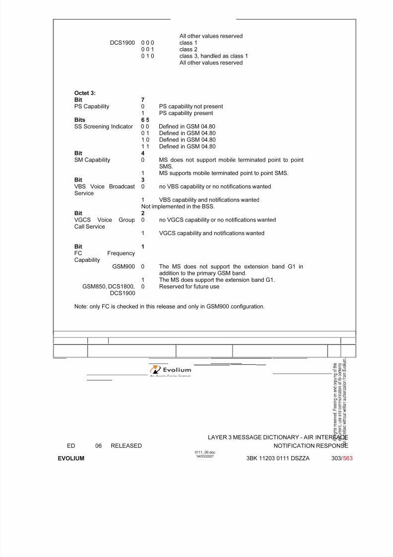
7/11/2019 1. Layer3 Air Interface Messages 0111_06
http://slidepdf.com/reader/full/1-layer3-air-interface-messages-011106 303/562
LAYER 3 MESSAGE DICTIONARY - AIR INTERFACE
ED 06 RELEASED NOTIFICATION RESPONSE
EVOLIUM
0111_06.doc14/03/2007
3BK 11203 0111 DSZZA 303/ 563
All other values reservedDCS1900 0 0 0 class 1
0 0 1 class 20 1 0 class 3, handled as class 1
All other values reserved
Octet 3:Bit 7PS Capability 0 PS capability not present
1 PS capability presentBits 6 5SS Screening Indicator 0 0 Defined in GSM 04.80
0 1 Defined in GSM 04.801 0 Defined in GSM 04.801 1 Defined in GSM 04.80
Bit 4SM Capability 0 MS does not support mobile terminated point to point
SMS.
1 MS supports mobile terminated point to point SMS.Bit 3VBS Voice BroadcastService
0 no VBS capability or no notifications wanted
1 VBS capability and notifications wantedNot implemented in the BSS.
Bit 2VGCS Voice GroupCall Service
0 no VGCS capability or no notifications wanted
1 VGCS capability and notifications wanted
Bit 1FC FrequencyCapability
GSM900 0 The MS does not support the extension band G1 inaddition to the primary GSM band.
1 The MS does support the extension band G1.GSM850, DCS1800,
DCS19000 Reserved for future use
Note: only FC is checked in this release and only in GSM900 configuration.

7/11/2019 1. Layer3 Air Interface Messages 0111_06
http://slidepdf.com/reader/full/1-layer3-air-interface-messages-011106 304/562
LAYER 3 MESSAGE DICTIONARY - AIR INTERFACE
ED 06 RELEASED NOTIFICATION RESPONSE
EVOLIUM
0111_06.doc14/03/2007
3BK 11203 0111 DSZZA 304/ 563
Octet 4Bit 8CM3 Classmark 3 0 No additional MS capability
1 Additional MS capabilities are described in the MSClassmark 3 information element.
Bit 6LCS VA capability 0 LCS value added location request notification capability not
supported1 LCS value added location request notification capabilitysupported
Not implemented in the BSS.Bit 5UCS2 treatment 0 the ME has a preference for the default alphabet (defined in
GSM 03.38) over UCS21 the ME has no preference between the use of the default
alphabet and the use of UCS2.Not implemented in the BSS.
Bit 4SoLSA 0 The ME does not support SoLSA
1 The ME supports SoLSA.
Bit 3CMSP: CM Service Prompt 0 "Network initiated MO CM connection request" not supported1 "Network initiated MO CM connection request" supported for
at least one CM protocol.Not implemented in the BSS.
Bit 2A5/3 algorithm supported 0 A5/3 not available
1 A5/3 available
Bit 1A5/2 algorithm supported 0 A5/2 not available
1 A5/2 availableNote: only A5/2 is checked in this release.
PARAMETER ORIGIN - ACTION ON PARAMETER
The BSC takes this information in order to have the MS power capability for the power controlalgorithm, the MS frequency capability and the MS ciphering capability.Additional mobile info can be obtained by invoking the classmark interrogation procedure.

7/11/2019 1. Layer3 Air Interface Messages 0111_06
http://slidepdf.com/reader/full/1-layer3-air-interface-messages-011106 305/562
LAYER 3 MESSAGE DICTIONARY - AIR INTERFACE
ED 06 RELEASED NOTIFICATION RESPONSE
EVOLIUM
0111_06.doc14/03/2007
3BK 11203 0111 DSZZA 305/ 563
6.35.3 Mobile Identity
TYPE: M
DEFINITIONTo provide either the IMSI, the TMSI or the IMEI. IMEISV is not used.
Note IMSI ≤ 15 digitsTMSI = 4 octetsIMEI = 15 digits
BIT DESCRIPTION
8 7 6 5 4 3 2 1
Length of Mobile Identity contents
ID digit 1 OEI Type of ID
ID digit 3 ID digit 2
: :
ID digit p+1 ID digit P
SUB PARAMETER DEFINITION
Type of ID: 0 0 1 IMSI0 1 0 IMEI Not used
0 1 1 IMEISV Not used1 0 0 TMSI0 0 0 No identity Not usedother values reserved
OEI: Odd Even Indicator
value 0: even number of identity digits (even for TMSI)1: odd number of digits
Filled digit :1 1 1 1
Octet 2
For the IMSI and the IMEI this field is coded using BCD coding. If the number of identify digits is eventhen bits 5 to 8 of the last octet shall be filled with an end mark coded as '1111'.If the mobile identity is the TMSI then bits 5 to 8 of octet 2 is coded as '1111' and bit 8 of octet 3 is themost significant bit, and bit 1 of the last octet is the least significant bit.
PARAMETER ORIGIN - ACTION ON PARAMETERBSC transparent.

7/11/2019 1. Layer3 Air Interface Messages 0111_06
http://slidepdf.com/reader/full/1-layer3-air-interface-messages-011106 306/562
LAYER 3 MESSAGE DICTIONARY - AIR INTERFACE
ED 06 RELEASED NOTIFICATION RESPONSE
EVOLIUM
0111_06.doc14/03/2007
3BK 11203 0111 DSZZA 306/ 563
6.35.4 Group or broadcast Call reference
TYPE: M
DEFINITION
Descriptive Group or Broadcast Call Reference provides information describing a voice group or
broadcast call
BIT DESCRIPTION
8 7 6 5 4 3 2 1
Binary coding of the group or broadcast call reference octet 1
octet 2
octet 3
SF AF call priority octet 4
SpareCiphering information 0 0 0 0 octet 5
SF Service flag (octet 5)Bit 50 VBS (broadcast call reference) Not used1 VGCS (group call reference)
AF Acknowledgement flag (octet 5), MS to network direction:Bit 4 is spare and shall be set to "0".
Call priority (octet 5)Bits 1 to 3 are spare and shall be set to "0".
Ciphering information (octet 6)Bits 5 to 8 are spare and shall be set to "0".
PARAMETER ORIGIN - ACTION ON PARAMETERTransparently sent through the BSS.

7/11/2019 1. Layer3 Air Interface Messages 0111_06
http://slidepdf.com/reader/full/1-layer3-air-interface-messages-011106 307/562
LAYER 3 MESSAGE DICTIONARY - AIR INTERFACE
ED 06 RELEASED PAGING REQUEST TYPE 1
EVOLIUM
0111_06.doc14/03/2007
3BK 11203 0093 DSZZA 307/ 563
6.36 PAGING REQUEST TYPE 1
NAME PAGING REQUEST TYPE 1
INTERFACE RADIO ABIS A
CHANNEL/ USAGE
CCCH(PCH)
3GPP-REF 44.018
FUNCTION This message is sent on the PCH by the network to up to two mobile stations totrigger channel access. The mobile stations are identified by their (P)TMSI or IMSI.
DIRECTION From: BTS To: MS
INFORMATION ELEMENT NAME TYPE COMMENT LENGTH(byte)
INFORMATIONELEMENT
LISTL2 Pseudo LengthHeader Page ModeChannel Needed for Mobiles 1 & 2Mobile Identity 1Mobile Identity 2P1 Rest Octets
M V M V M V M V M LV O TLV M V
Note 1
12½½
2-93-100-17
IMPLEMENTATION MAXIMUM LENGTH 23
NORMAL SITUATION ABNORMAL SITUATION TIMER
FOLLOWINGEVENT
MS accesses the CCCH No response to paging
SPECIFDOC. REF.
Paging and Access Grant Control (ref. [1])
(1) The channel needed is set to 'Any Channel'
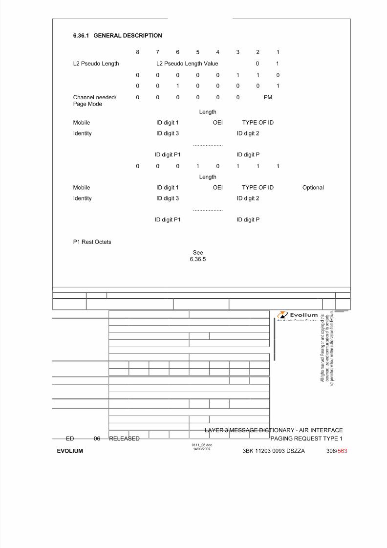
7/11/2019 1. Layer3 Air Interface Messages 0111_06
http://slidepdf.com/reader/full/1-layer3-air-interface-messages-011106 308/562
LAYER 3 MESSAGE DICTIONARY - AIR INTERFACE
ED 06 RELEASED PAGING REQUEST TYPE 1
EVOLIUM
0111_06.doc14/03/2007
3BK 11203 0093 DSZZA 308/ 563
6.36.1 GENERAL DESCRIPTION
8 7 6 5 4 3 2 1
L2 Pseudo Length L2 Pseudo Length Value 0 1
0 0 0 0 0 1 1 0
0 0 1 0 0 0 0 1
Channel needed/ Page Mode
0 0 0 0 0 0 PM
Length
Mobile ID digit 1 OEI TYPE OF ID
Identity ID digit 3 ID digit 2
...................
ID digit P1 ID digit P
0 0 0 1 0 1 1 1Length
Mobile ID digit 1 OEI TYPE OF ID Optional
Identity ID digit 3 ID digit 2
...................
ID digit P1 ID digit P
P1 Rest Octets
See6.36.5
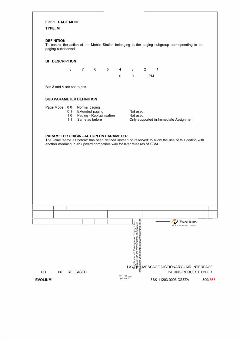
7/11/2019 1. Layer3 Air Interface Messages 0111_06
http://slidepdf.com/reader/full/1-layer3-air-interface-messages-011106 309/562
LAYER 3 MESSAGE DICTIONARY - AIR INTERFACE
ED 06 RELEASED PAGING REQUEST TYPE 1
EVOLIUM
0111_06.doc14/03/2007
3BK 11203 0093 DSZZA 309/ 563
6.36.2 PAGE MODE
TYPE: M
DEFINITIONTo control the action of the Mobile Station belonging to the paging subgroup corresponding to thepaging subchannel.
BIT DESCRIPTION
8 7 6 5 4 3 2 1
0 0 PM
Bits 3 and 4 are spare bits.
SUB PARAMETER DEFINITION
Page Mode 0 0 Normal paging0 1 Extended paging Not used1 0 Paging - Reorganisation Not used1 1 Same as before Only supported in Immediate Assignment
PARAMETER ORIGIN - ACTION ON PARAMETERThe value 'same as before' has been defined instead of 'reserved' to allow the use of this coding withanother meaning in an upward compatible way for later releases of GSM.

7/11/2019 1. Layer3 Air Interface Messages 0111_06
http://slidepdf.com/reader/full/1-layer3-air-interface-messages-011106 310/562
LAYER 3 MESSAGE DICTIONARY - AIR INTERFACE
ED 06 RELEASED PAGING REQUEST TYPE 1
EVOLIUM
0111_06.doc14/03/2007
3BK 11203 0093 DSZZA 310/ 563
6.36.3 CHANNELS NEEDED FOR MOBILES 1 & 2
TYPE: M
DEFINITIONTo indicate what channel is required for the transaction linked to the paging procedure.
BIT DESCRIPTION
8 7 6 5 4 3 2 1
Channel 2 Channel 1
SUB PARAMETER DEFINITION
Channel 1 00 Any Channel Supported
01 SDCCH Not supported10 TCH/F Not supported11 TCH/H or TCH/F Not supported
The field Channel 2 uses the same coding.
PARAMETER ORIGIN - ACTION ON PARAMETER
6.36.4 MOBILE IDENTITY
TYPE: M Mobile Identity 1O Mobile Identity 2
DEFINITIONTo provide either the IMSI, the (P)TMSI, but not the IMEI or IMEISV
Note IMSI ≤ 15 digits(P)TMSI = 4 octets
BIT DESCRIPTION
8 7 6 5 4 3 2 1
0 0 0 1 0 1 1 1 *
Length
ID digit 1 OEI TYPE OF ID
ID digit 3 ID digit 2
...................
ID digit P1 ID digit P
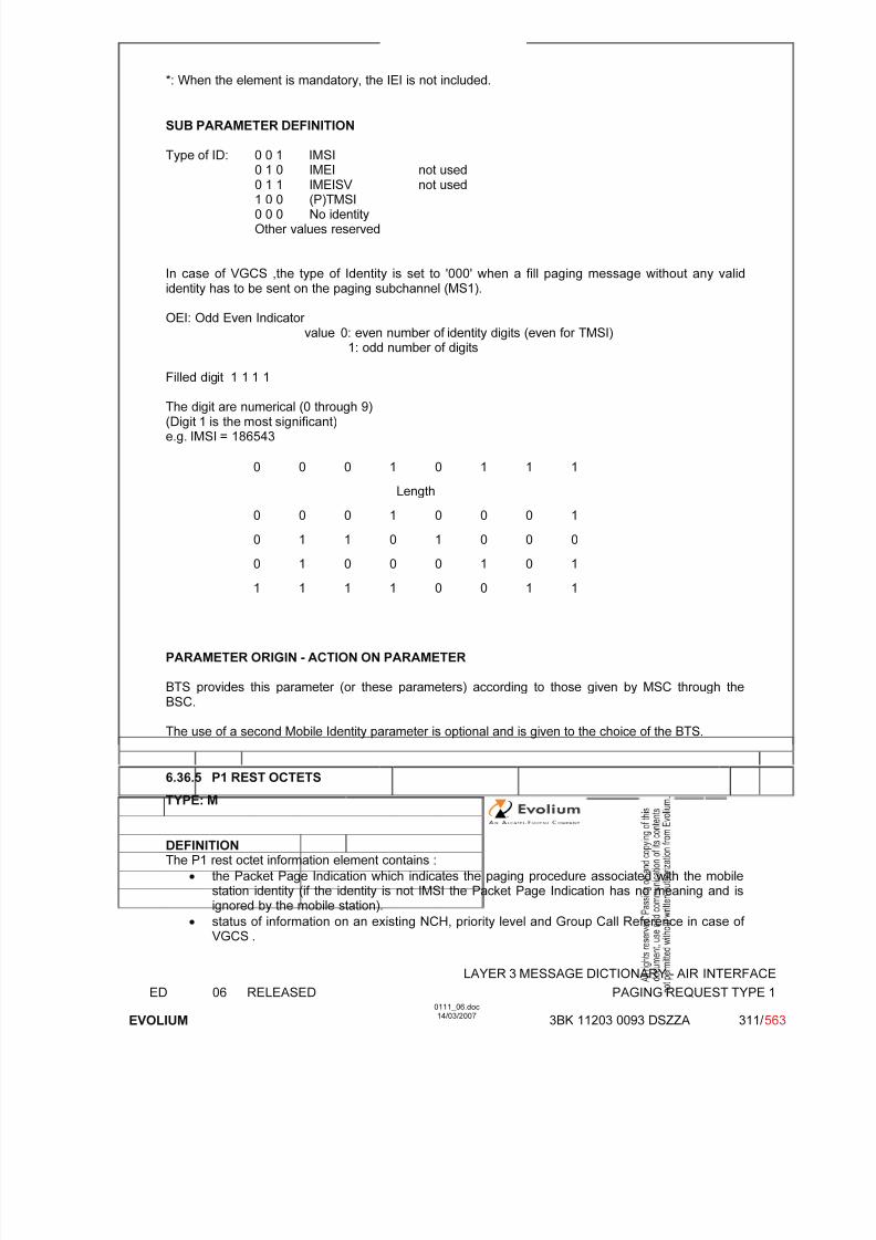
7/11/2019 1. Layer3 Air Interface Messages 0111_06
http://slidepdf.com/reader/full/1-layer3-air-interface-messages-011106 311/562
LAYER 3 MESSAGE DICTIONARY - AIR INTERFACE
ED 06 RELEASED PAGING REQUEST TYPE 1
EVOLIUM
0111_06.doc14/03/2007
3BK 11203 0093 DSZZA 311/ 563
*: When the element is mandatory, the IEI is not included.
SUB PARAMETER DEFINITION
Type of ID: 0 0 1 IMSI0 1 0 IMEI not used
0 1 1 IMEISV not used1 0 0 (P)TMSI0 0 0 No identityOther values reserved
In case of VGCS ,the type of Identity is set to '000' when a fill paging message without any valididentity has to be sent on the paging subchannel (MS1).
OEI: Odd Even Indicator value 0: even number of identity digits (even for TMSI)
1: odd number of digits
Filled digit 1 1 1 1
The digit are numerical (0 through 9)(Digit 1 is the most significant)e.g. IMSI = 186543
0 0 0 1 0 1 1 1
Length
0 0 0 1 0 0 0 1
0 1 1 0 1 0 0 0
0 1 0 0 0 1 0 1
1 1 1 1 0 0 1 1
PARAMETER ORIGIN - ACTION ON PARAMETER
BTS provides this parameter (or these parameters) according to those given by MSC through theBSC.
The use of a second Mobile Identity parameter is optional and is given to the choice of the BTS.
6.36.5 P1 REST OCTETS
TYPE: M
DEFINITIONThe P1 rest octet information element contains :
• the Packet Page Indication which indicates the paging procedure associated with the mobilestation identity (if the identity is not IMSI the Packet Page Indication has no meaning and isignored by the mobile station).
• status of information on an existing NCH, priority level and Group Call Reference in case of VGCS .
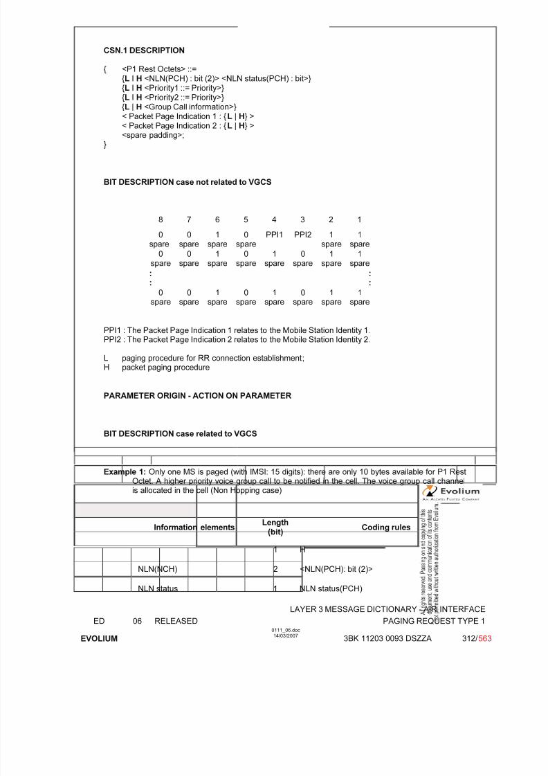
7/11/2019 1. Layer3 Air Interface Messages 0111_06
http://slidepdf.com/reader/full/1-layer3-air-interface-messages-011106 312/562
LAYER 3 MESSAGE DICTIONARY - AIR INTERFACE
ED 06 RELEASED PAGING REQUEST TYPE 1
EVOLIUM
0111_06.doc14/03/2007
3BK 11203 0093 DSZZA 312/ 563
CSN.1 DESCRIPTION
{ <P1 Rest Octets> ::={L I H <NLN(PCH) : bit (2)> <NLN status(PCH) : bit>}{L I H <Priority1 ::= Priority>}{L I H <Priority2 ::= Priority>}{L | H <Group Call information>}
< Packet Page Indication 1 : {L | H} >< Packet Page Indication 2 : {L | H} ><spare padding>;
}
BIT DESCRIPTION case not related to VGCS
8 7 6 5 4 3 2 1
0spare 0spare 1spare 0spare PPI1 PPI2 1spare 1spare
0spare
0spare
1spare
0spare
1spare
0spare
1spare
1spare
::
::
0spare
0spare
1spare
0spare
1spare
0spare
1spare
1spare
PPI1 : The Packet Page Indication 1 relates to the Mobile Station Identity 1.PPI2 : The Packet Page Indication 2 relates to the Mobile Station Identity 2.
L paging procedure for RR connection establishment;H packet paging procedure
PARAMETER ORIGIN - ACTION ON PARAMETER
BIT DESCRIPTION case related to VGCS
Example 1: Only one MS is paged (with IMSI: 15 digits): there are only 10 bytes available for P1 RestOctet. A higher priority voice group call to be notified in the cell. The voice group call channelis allocated in the cell (Non Hopping case)
Information elements Length
(bit)Coding rules
1 H
NLN(NCH) 2 <NLN(PCH): bit (2)>
NLN status 1 NLN status(PCH)
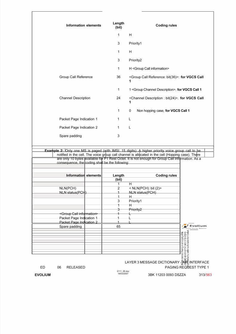
7/11/2019 1. Layer3 Air Interface Messages 0111_06
http://slidepdf.com/reader/full/1-layer3-air-interface-messages-011106 313/562
LAYER 3 MESSAGE DICTIONARY - AIR INTERFACE
ED 06 RELEASED PAGING REQUEST TYPE 1
EVOLIUM
0111_06.doc14/03/2007
3BK 11203 0093 DSZZA 313/ 563
Information elements Length
(bit)Coding rules
1 H
3 Priority1
1 H
3 Priority2
1 H <Group Call information>
Group Call Reference 36 <Group Call Reference: bit(36)>: for VGCS Call1
1 1 <Group Channel Description>, for VGCS Call 1
Channel Description 24 <Channel Description : bit(24)>, for VGCS Call
1
1 0 Non hopping case, for VGCS Call 1
Packet Page Indication 1 1 L
Packet Page Indication 2 1 L
Spare padding 3
Example 2: Only one MS is paged (with IMSI: 15 digits): A higher priority voice group call to be
notified in the cell. The voice group call channel is allocated in the cell (Hopping case). Thereare only 10 bytes available for P1 Rest Octet. It is not enough for Group Call information. As aconsequence, the coding shall be the following:
Information elements Length(bit)
Coding rules
1 H
NLN(PCH) 2 < NLN(PCH): bit (2)>
NLN status(PCH) 1 NLN status(PCH)
1 H
3 Priority1
1 H3 Priority2
<Group Call information> 1 L
Packet Page Indication 1 1 L
Packet Page Indication 2 1 L
Spare padding 65

7/11/2019 1. Layer3 Air Interface Messages 0111_06
http://slidepdf.com/reader/full/1-layer3-air-interface-messages-011106 314/562
LAYER 3 MESSAGE DICTIONARY - AIR INTERFACE
ED 06 RELEASED PAGING REQUEST TYPE 1
EVOLIUM
0111_06.doc14/03/2007
3BK 11203 0093 DSZZA 314/ 563
Example 3:
There is NO mobile station to be paged.
A higher priority voice group call to be notified in the cell.
The voice group call channel is allocated in the cell (Hopping case).
Number of radio frequencies equal to 12;
There are only 17 bytes available for P1 Rest Octet (since Type of ID is 000, only needs twobytes, see 6.36.4 ). The coding shall be the following:
Information elements Length
(bit)
Coding rules
1 H
NLN(PCH) 2 < NLN(PCH): bit (2)>
NLN status(PCH) 1 NLN status(PCH)
1 H
3 Priority1
1 H
3 Priority2
1 H <Group Call information>
Group Call Reference 36 <Group Call Reference: bit(36)>: for VGCS Call1
1 1 <Group Channel Description>, for VGCS Call 1
Channel Description 24 <Channel Description : bit(24)>, for VGCS Call1
1 1 hopping case, for VGCS Call 1
1 0 Mobile Allocation
24 Mobile allocation
Packet Page Indication 1 1 L
Packet Page Indication 2 1 L
Spare padding 44
PARAMETER DESCRIPTION
NLN(PCH) : Notification List Number The presence of the NLN(PCH) field indicates that if an NCH is present, reduced NCH monitoring canbe used, and gives the NLN(PCH) value.
Priority: Priority 1 relates to Mobile Station Identity
0 0 0 no priority applied
0 0 1 call priority level 4
0 1 0 call priority level 3
0 1 1 call priority level 2
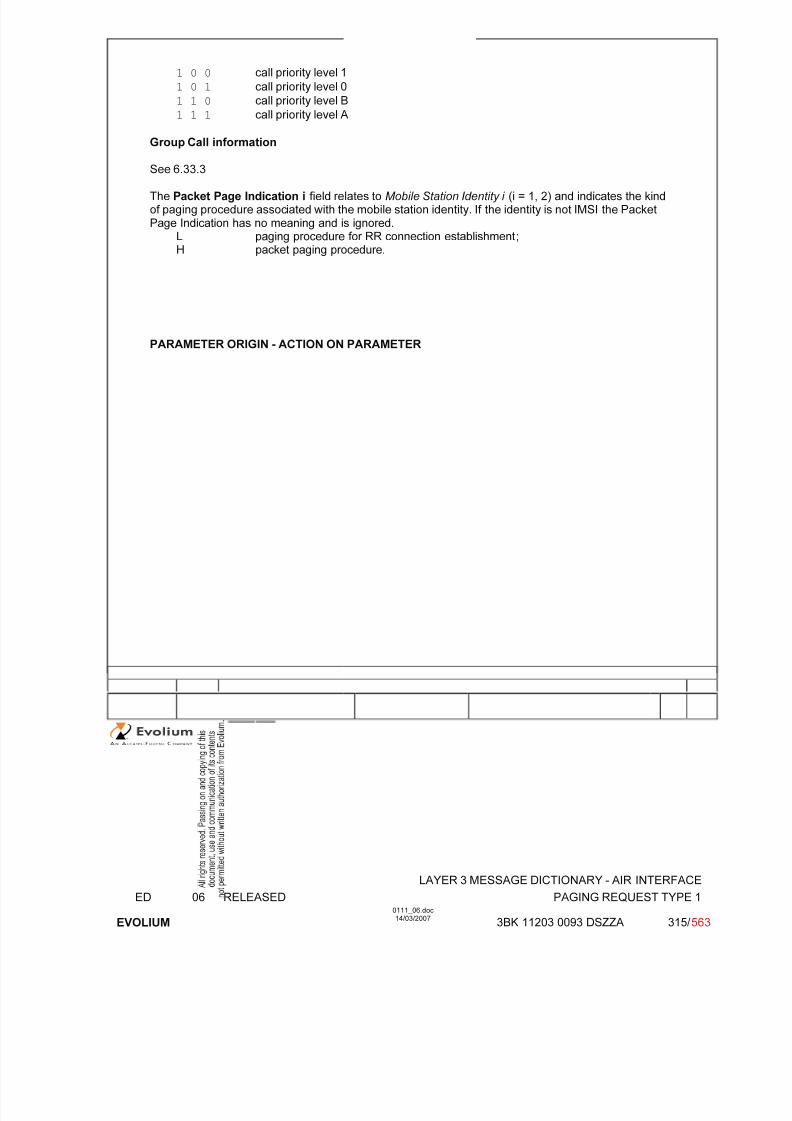
7/11/2019 1. Layer3 Air Interface Messages 0111_06
http://slidepdf.com/reader/full/1-layer3-air-interface-messages-011106 315/562
LAYER 3 MESSAGE DICTIONARY - AIR INTERFACE
ED 06 RELEASED PAGING REQUEST TYPE 1
EVOLIUM
0111_06.doc14/03/2007
3BK 11203 0093 DSZZA 315/ 563
1 0 0 call priority level 1
1 0 1 call priority level 0
1 1 0 call priority level B
1 1 1 call priority level A
Group Call information
See 6.33.3
The Packet Page Indication i field relates to Mobile Station Identity i (i = 1, 2) and indicates the kindof paging procedure associated with the mobile station identity. If the identity is not IMSI the PacketPage Indication has no meaning and is ignored.
L paging procedure for RR connection establishment;H packet paging procedure.
PARAMETER ORIGIN - ACTION ON PARAMETER

7/11/2019 1. Layer3 Air Interface Messages 0111_06
http://slidepdf.com/reader/full/1-layer3-air-interface-messages-011106 316/562
LAYER 3 MESSAGE DICTIONARY - AIR INTERFACE
ED 06 RELEASED PAGING REQUEST TYPE 2
EVOLIUM
0111_06.doc14/03/2007
3BK 11203 0111 DSZZA 316/ 563
6.37 PAGING REQUEST TYPE 2
NAME PAGING REQUEST TYPE 2
INTERFACE RADIO ABIS A
CHANNEL/ USAGE
CCCH(PCH)
3GPP-REF 44.018
FUNCTION This message is sent on the PCH by the network to up to three mobile stations totrigger channel access by these. The mobile stations are identified by their (P)TMSI or IMSI.
DIRECTION From: BTS To: MS
INFORMATION ELEMENT NAME TYPE COMMENT LENGTH(byte)
INFORMATIONELEMENT
LISTL2 Pseudo LengthHeader Page ModeChannels Needed for mobiles 1 & 2Mobile Identity 1Mobile Identity 2Mobile Identity 3P2 Rest Octets
M V
M V M V M V M V O TLV M V
(2)
(1)
12½½44
3-101-11
IMPLEMENTATION MAXIMUM LENGTH 23
NORMAL SITUATION ABNORMAL SITUATION TIMER
FOLLOWINGEVENT MS accesses the CCCH No response to paging
SPECIFDOC. REF.
Paging and Access Grant Control (ref. [1])
(1) Always present.(2) The channel needed is set to 'Any Channel'

7/11/2019 1. Layer3 Air Interface Messages 0111_06
http://slidepdf.com/reader/full/1-layer3-air-interface-messages-011106 317/562
LAYER 3 MESSAGE DICTIONARY - AIR INTERFACE
ED 06 RELEASED PAGING REQUEST TYPE 2
EVOLIUM
0111_06.doc14/03/2007
3BK 11203 0111 DSZZA 317/ 563
GENERAL DESCRIPTION
8 7 6 5 4 3 2 1
L2 Pseudo Length L2 Pseudo Length Value 0 1
0 0 0 0 0 1 1 0
0 0 1 0 0 0 1 0
Channels neededfor mobiles 1 & 2/ Page Mode
0 0 0 0 0 0 PM
(P)TMSI octet 1
TMSI (P)TMSI octet 2
MS 1 (P)TMSI octet 3
(P)TMSI octet 4
(P)TMSI octet 1
TMSI (P)TMSI octet 2
MS 2 (P)TMSI octet 3
(P)TMSI octet 4
0 0 0 1 0 1 1 1
Mobile Length
Identity ID digit 1 OEI TYPE OF ID
MS 3 ID digit 3 ID digit 2
...................
ID digit P+1 ID digit P
P2 RestOctets
See6.37.5

7/11/2019 1. Layer3 Air Interface Messages 0111_06
http://slidepdf.com/reader/full/1-layer3-air-interface-messages-011106 318/562
LAYER 3 MESSAGE DICTIONARY - AIR INTERFACE
ED 06 RELEASED PAGING REQUEST TYPE 2
EVOLIUM
0111_06.doc14/03/2007
3BK 11203 0111 DSZZA 318/ 563
6.37.1 PAGE MODE
TYPE: M
DEFINITIONTo control the action of the Mobile Station belonging to the paging subgroup corresponding to thepaging subchannel.
BIT DESCRIPTION
8 7 6 5 4 3 2 1
0 0 PM
Bits 3 and 4 are spare bits.
SUB PARAMETER DEFINITION
Page Mode 0 0 Normal paging0 1 Extended paging Not used1 0 Paging - Reorganisation Not used1 1 Same as before Only used in Immediate Assignment
PARAMETER ORIGIN - ACTION ON PARAMETER
The value 'same as before' has been defined instead of 'reserved' to allow the use of this coding withanother meaning in an upward compatible way for later releases of GSM.
6.37.2 CHANNELS NEEDED FOR MOBILES 1 & 2
TYPE: M
DEFINITIONTo indicate what channel is required for the transaction linked to the paging procedure.
8 7 6 5 4 3 2 1
Channel 2 Channel 1
SUB PARAMETER DEFINITION
Channel 1 00 Any Channel01 SDCCH Not supported10 TCH/F Not supported11 TCH/H or TCH/F Not supported
The field Channel 2 uses the same coding.
PARAMETER ORIGIN - ACTION ON PARAMETER
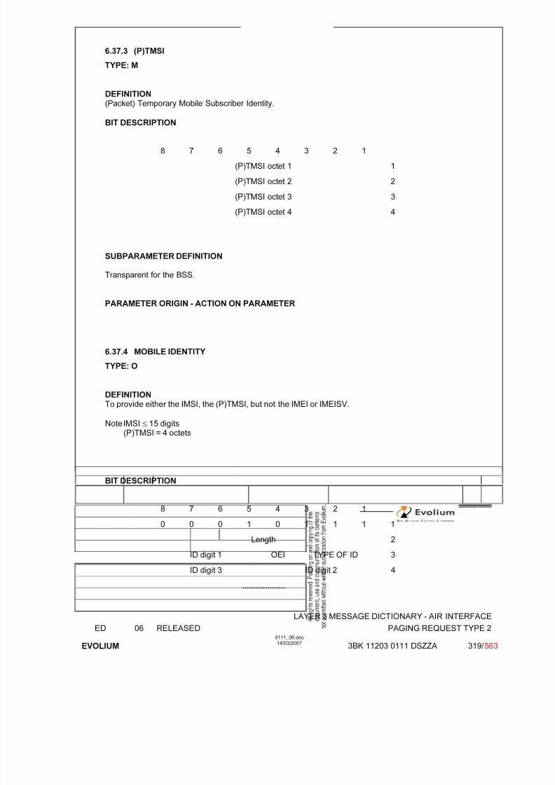
7/11/2019 1. Layer3 Air Interface Messages 0111_06
http://slidepdf.com/reader/full/1-layer3-air-interface-messages-011106 319/562
LAYER 3 MESSAGE DICTIONARY - AIR INTERFACE
ED 06 RELEASED PAGING REQUEST TYPE 2
EVOLIUM
0111_06.doc14/03/2007
3BK 11203 0111 DSZZA 319/ 563
6.37.3 (P)TMSI
TYPE: M
DEFINITION(Packet) Temporary Mobile Subscriber Identity.
BIT DESCRIPTION
8 7 6 5 4 3 2 1
(P)TMSI octet 1 1
(P)TMSI octet 2 2
(P)TMSI octet 3 3
(P)TMSI octet 4 4
SUBPARAMETER DEFINITION
Transparent for the BSS.
PARAMETER ORIGIN - ACTION ON PARAMETER
6.37.4 MOBILE IDENTITY
TYPE: O
DEFINITIONTo provide either the IMSI, the (P)TMSI, but not the IMEI or IMEISV.
Note IMSI ≤ 15 digits(P)TMSI = 4 octets
BIT DESCRIPTION
8 7 6 5 4 3 2 1
0 0 0 1 0 1 1 1 1
Length 2
ID digit 1 OEI TYPE OF ID 3
ID digit 3 ID digit 2 4
...................
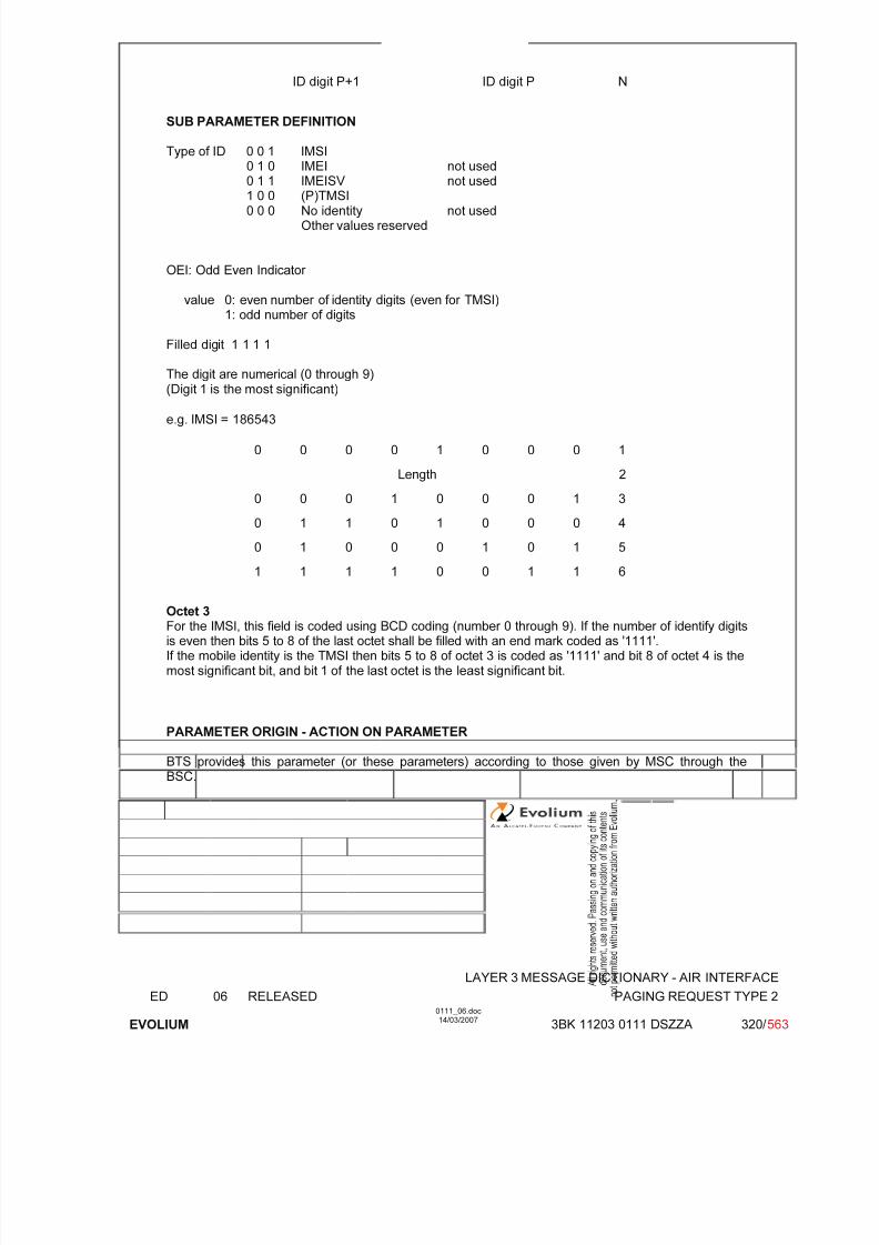
7/11/2019 1. Layer3 Air Interface Messages 0111_06
http://slidepdf.com/reader/full/1-layer3-air-interface-messages-011106 320/562
LAYER 3 MESSAGE DICTIONARY - AIR INTERFACE
ED 06 RELEASED PAGING REQUEST TYPE 2
EVOLIUM
0111_06.doc14/03/2007
3BK 11203 0111 DSZZA 320/ 563
ID digit P+1 ID digit P N
SUB PARAMETER DEFINITION
Type of ID 0 0 1 IMSI0 1 0 IMEI not used0 1 1 IMEISV not used
1 0 0 (P)TMSI0 0 0 No identity not used
Other values reserved
OEI: Odd Even Indicator
value 0: even number of identity digits (even for TMSI)1: odd number of digits
Filled digit 1 1 1 1
The digit are numerical (0 through 9)(Digit 1 is the most significant)
e.g. IMSI = 186543
0 0 0 0 1 0 0 0 1
Length 2
0 0 0 1 0 0 0 1 3
0 1 1 0 1 0 0 0 4
0 1 0 0 0 1 0 1 5
1 1 1 1 0 0 1 1 6
Octet 3For the IMSI, this field is coded using BCD coding (number 0 through 9). If the number of identify digitsis even then bits 5 to 8 of the last octet shall be filled with an end mark coded as '1111'.If the mobile identity is the TMSI then bits 5 to 8 of octet 3 is coded as '1111' and bit 8 of octet 4 is themost significant bit, and bit 1 of the last octet is the least significant bit.
PARAMETER ORIGIN - ACTION ON PARAMETER
BTS provides this parameter (or these parameters) according to those given by MSC through theBSC.
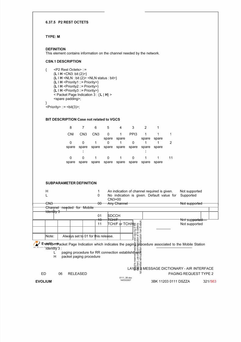
7/11/2019 1. Layer3 Air Interface Messages 0111_06
http://slidepdf.com/reader/full/1-layer3-air-interface-messages-011106 321/562
LAYER 3 MESSAGE DICTIONARY - AIR INTERFACE
ED 06 RELEASED PAGING REQUEST TYPE 2
EVOLIUM
0111_06.doc14/03/2007
3BK 11203 0111 DSZZA 321/ 563
6.37.5 P2 REST OCTETS
TYPE: M
DEFINITION
This element contains information on the channel needed by the network.
CSN.1 DESCRIPTION
{ <P2 Rest Octets> ::={L I H <CN3: bit (2)>}{L I H <NLN : bit (2)> <NLN status : bit>}{L I H <Priority1 ::= Priority>}{L I H <Priority2 ::= Priority>}{L I H <Priority3 ::= Priority>}
< Packet Page Indication 3 : {L | H} ><spare padding>;
}<Priority> ::= <bit(3)>;
BIT DESCRIPTION Case not related to VGCS
8 7 6 5 4 3 2 1
CNI CN3 CN3 0spare
1spare
PPI3 1spare
1spare
1
0spare
0spare
1spare
0spare
1spare
0spare
1spare
1spare
2
: :
0spare
0spare
1spare
0spare
1spare
0spare
1spare
1spare
11
SUBPARAMETER DEFINITION
H 1 An indication of channel required is given. Not supportedL 0 No indication is given. Default value for
CN3=00Supported
CN3Channel needed for Mobile
Identity 3
00 Any Channel Not supported
01 SDCCH10 TCH/F Not supported11 TCH/F or TCH/H Not supported
Note: Always set to 01 for this release.
PPI3 : Packet Page Indication which indicates the paging procedure associated to the Mobile StationIdentity 3 :
L paging procedure for RR connection establishment;H packet paging procedure
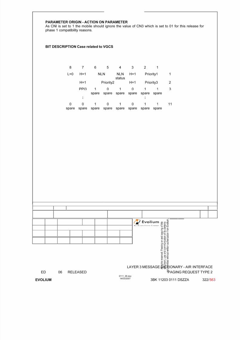
7/11/2019 1. Layer3 Air Interface Messages 0111_06
http://slidepdf.com/reader/full/1-layer3-air-interface-messages-011106 322/562
LAYER 3 MESSAGE DICTIONARY - AIR INTERFACE
ED 06 RELEASED PAGING REQUEST TYPE 2
EVOLIUM
0111_06.doc14/03/2007
3BK 11203 0111 DSZZA 322/ 563
PARAMETER ORIGIN - ACTION ON PARAMETERAs CNI is set to 1 the mobile should ignore the value of CN3 which is set to 01 for this release for phase 1 compatibility reasons.
BIT DESCRIPTION Case related to VGCS
8 7 6 5 4 3 2 1
L=0 H=1 NLN NLNstatus
H=1 Priority1 1
H=1 Priority2 H=1 Priority3 2
PPI3 1spare
0spare
1spare
0spare
1spare
1spare
3
: :
0spare
0spare
1spare
0spare
1spare
0spare
1spare
1spare
11

7/11/2019 1. Layer3 Air Interface Messages 0111_06
http://slidepdf.com/reader/full/1-layer3-air-interface-messages-011106 323/562
LAYER 3 MESSAGE DICTIONARY - AIR INTERFACE
ED 06 RELEASED PAGING REQUEST TYPE 2
EVOLIUM
0111_06.doc14/03/2007
3BK 11203 0111 DSZZA 323/ 563
SUBPARAMETER DEFINITION
NLN(PCH) : Notification List Number The presence of the NLN(PCH) field indicates that if an NCH is present, reduced NCH monitoring canbe used, and gives the NLN(PCH) value.
Priority: Priority i relates to Mobile Station Identity i (i = 1, 2, 3)0 0 0 no priority applied
0 0 1 call priority level 4
0 1 0 call priority level 3
0 1 1 call priority level 2
1 0 0 call priority level 1
1 0 1 call priority level 0
1 1 0 call priority level B
1 1 1 call priority level A
The Packet Page Indication 3 field relates to Mobile Station Identity 3 and indicates the kind of paging procedure associated with the mobile station identity. If the identity is not IMSI the Packet Page
Indication has no meaning and is ignored.L paging procedure for RR connection establishment;H packet paging procedure.

7/11/2019 1. Layer3 Air Interface Messages 0111_06
http://slidepdf.com/reader/full/1-layer3-air-interface-messages-011106 324/562
LAYER 3 MESSAGE DICTIONARY - AIR INTERFACE
ED 06 RELEASED PAGING REQUEST TYPE 3
EVOLIUM
0111_06.doc14/03/2007
3BK 11203 0111 DSZZA 324/ 563
6.38 PAGING REQUEST TYPE 3
NAME PAGING REQUEST TYPE 3
INTERFACE RADIO ABIS A
CHANNEL/ USAGE
CCCH(PCH)
3GPP-REF 44.018
FUNCTION This message is sent on the PCH by the network to up to four mobile stations totrigger channel access by these. The mobile stations are identified by their TMSI.
DIRECTION From: BTS To: MS
INFORMATION ELEMENT NAME TYPE COMMENT LENGTH(byte)
INFORMATIONELEMENT
LISTL2 Pseudo LengthHeader Page ModeChannels needed for MS 1 & 2Mobile Identity 1Mobile Identity 2Mobile Identity 3Mobile Identity 4P3 Rest Octets
M V
M V M V M V M V M V M V M V
(1)
12½½44443
IMPLEMENTATION MAXIMUM LENGTH 23
NORMAL SITUATION ABNORMAL SITUATION TIMER
FOLLOWINGEVENT MS accesses the CCCH No response to paging
SPECIFDOC. REF.
Paging and Access Grant Control (ref. [1])
(1) The channel needed is set to 'Any Channel'
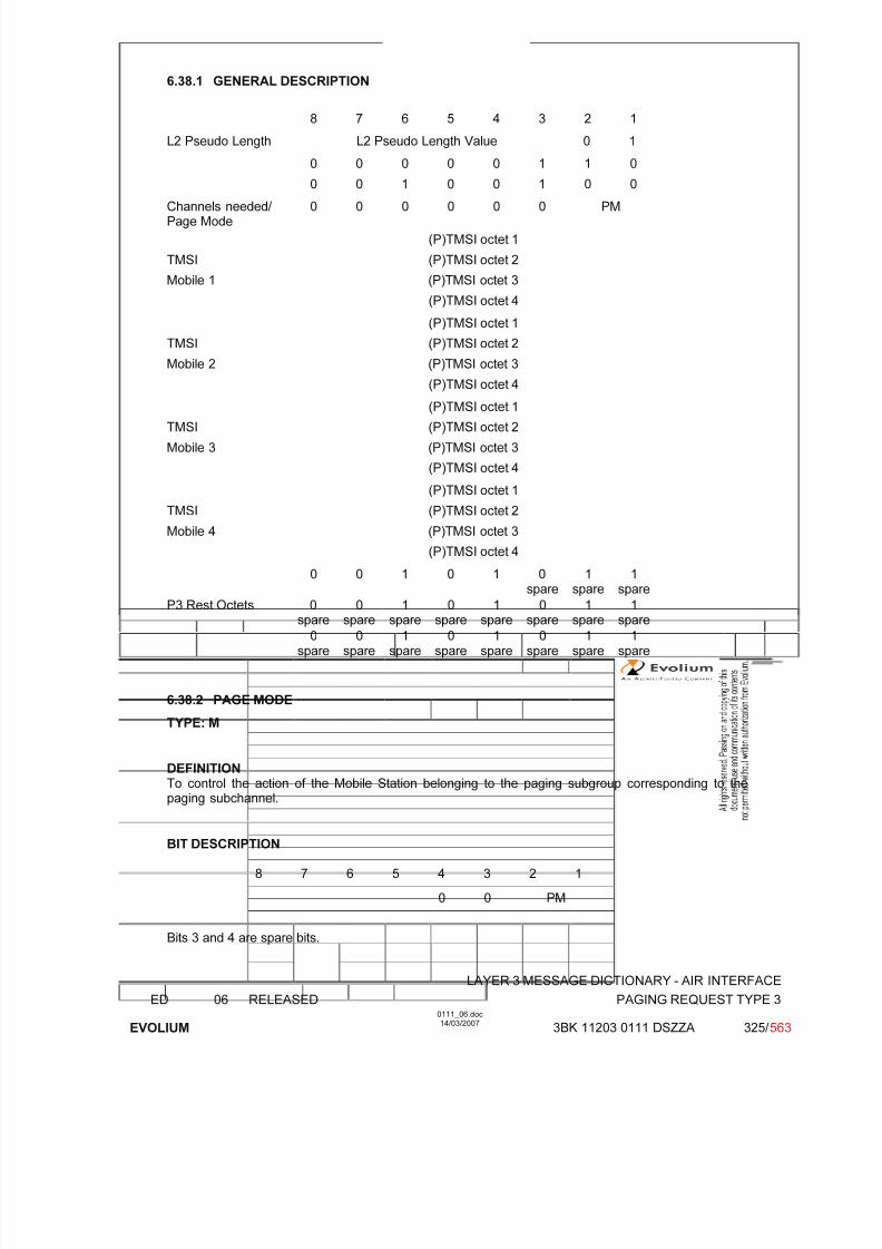
7/11/2019 1. Layer3 Air Interface Messages 0111_06
http://slidepdf.com/reader/full/1-layer3-air-interface-messages-011106 325/562
LAYER 3 MESSAGE DICTIONARY - AIR INTERFACE
ED 06 RELEASED PAGING REQUEST TYPE 3
EVOLIUM
0111_06.doc14/03/2007
3BK 11203 0111 DSZZA 325/ 563
6.38.1 GENERAL DESCRIPTION
8 7 6 5 4 3 2 1
L2 Pseudo Length L2 Pseudo Length Value 0 1
0 0 0 0 0 1 1 0
0 0 1 0 0 1 0 0
Channels needed/ Page Mode
0 0 0 0 0 0 PM
(P)TMSI octet 1
TMSI (P)TMSI octet 2
Mobile 1 (P)TMSI octet 3
(P)TMSI octet 4
(P)TMSI octet 1
TMSI (P)TMSI octet 2
Mobile 2 (P)TMSI octet 3
(P)TMSI octet 4
(P)TMSI octet 1
TMSI (P)TMSI octet 2
Mobile 3 (P)TMSI octet 3
(P)TMSI octet 4
(P)TMSI octet 1
TMSI (P)TMSI octet 2
Mobile 4 (P)TMSI octet 3
(P)TMSI octet 4
0 0 1 0 1 0spare
1spare
1spare
P3 Rest Octets 0spare
0spare
1spare
0spare
1spare
0spare
1spare
1spare
0spare
0spare
1spare
0spare
1spare
0spare
1spare
1spare
6.38.2 PAGE MODE
TYPE: M
DEFINITIONTo control the action of the Mobile Station belonging to the paging subgroup corresponding to thepaging subchannel.
BIT DESCRIPTION
8 7 6 5 4 3 2 1
0 0 PM
Bits 3 and 4 are spare bits.
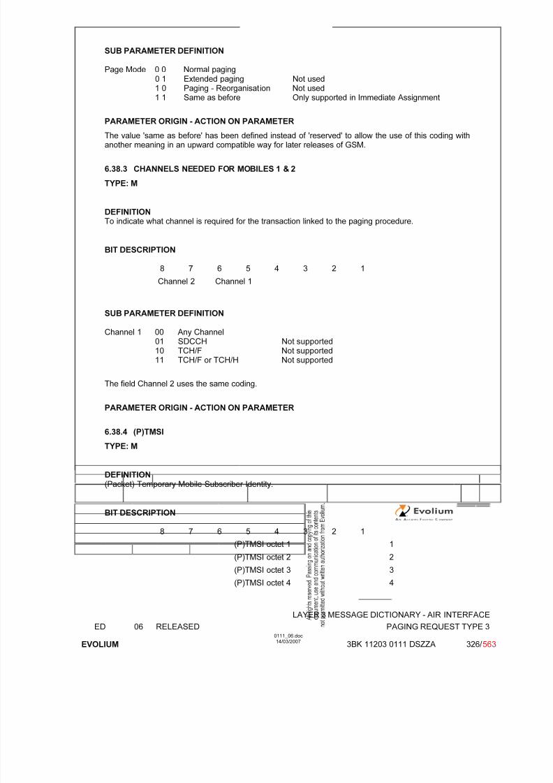
7/11/2019 1. Layer3 Air Interface Messages 0111_06
http://slidepdf.com/reader/full/1-layer3-air-interface-messages-011106 326/562
LAYER 3 MESSAGE DICTIONARY - AIR INTERFACE
ED 06 RELEASED PAGING REQUEST TYPE 3
EVOLIUM
0111_06.doc14/03/2007
3BK 11203 0111 DSZZA 326/ 563
SUB PARAMETER DEFINITION
Page Mode 0 0 Normal paging0 1 Extended paging Not used1 0 Paging - Reorganisation Not used1 1 Same as before Only supported in Immediate Assignment
PARAMETER ORIGIN - ACTION ON PARAMETER
The value 'same as before' has been defined instead of 'reserved' to allow the use of this coding withanother meaning in an upward compatible way for later releases of GSM.
6.38.3 CHANNELS NEEDED FOR MOBILES 1 & 2
TYPE: M
DEFINITIONTo indicate what channel is required for the transaction linked to the paging procedure.
BIT DESCRIPTION
8 7 6 5 4 3 2 1
Channel 2 Channel 1
SUB PARAMETER DEFINITION
Channel 1 00 Any Channel01 SDCCH Not supported10 TCH/F Not supported
11 TCH/F or TCH/H Not supported
The field Channel 2 uses the same coding.
PARAMETER ORIGIN - ACTION ON PARAMETER
6.38.4 (P)TMSI
TYPE: M
DEFINITION
(Packet) Temporary Mobile Subscriber Identity.
BIT DESCRIPTION
8 7 6 5 4 3 2 1
(P)TMSI octet 1 1
(P)TMSI octet 2 2
(P)TMSI octet 3 3
(P)TMSI octet 4 4
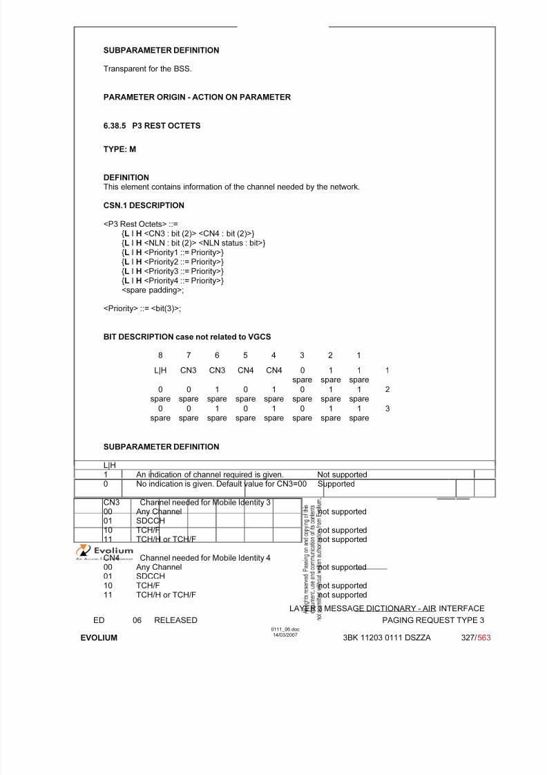
7/11/2019 1. Layer3 Air Interface Messages 0111_06
http://slidepdf.com/reader/full/1-layer3-air-interface-messages-011106 327/562
LAYER 3 MESSAGE DICTIONARY - AIR INTERFACE
ED 06 RELEASED PAGING REQUEST TYPE 3
EVOLIUM
0111_06.doc14/03/2007
3BK 11203 0111 DSZZA 327/ 563
SUBPARAMETER DEFINITION
Transparent for the BSS.
PARAMETER ORIGIN - ACTION ON PARAMETER
6.38.5 P3 REST OCTETS
TYPE: M
DEFINITIONThis element contains information of the channel needed by the network.
CSN.1 DESCRIPTION
<P3 Rest Octets> ::={L I H <CN3 : bit (2)> <CN4 : bit (2)>}{L I H <NLN : bit (2)> <NLN status : bit>}{L I H <Priority1 ::= Priority>}{L I H <Priority2 ::= Priority>}{L I H <Priority3 ::= Priority>}{L I H <Priority4 ::= Priority>}<spare padding>;
<Priority> ::= <bit(3)>;
BIT DESCRIPTION case not related to VGCS
8 7 6 5 4 3 2 1L|H CN3 CN3 CN4 CN4 0
spare1
spare1
spare1
0spare
0spare
1spare
0spare
1spare
0spare
1spare
1spare
2
0spare
0spare
1spare
0spare
1spare
0spare
1spare
1spare
3
SUBPARAMETER DEFINITION
L|H
1 An indication of channel required is given. Not supported0 No indication is given. Default value for CN3=00 Supported
CN3 Channel needed for Mobile Identity 300 Any Channel not supported01 SDCCH10 TCH/F not supported11 TCH/H or TCH/F not supported
CN4 Channel needed for Mobile Identity 400 Any Channel not supported01 SDCCH10 TCH/F not supported
11 TCH/H or TCH/F not supported

7/11/2019 1. Layer3 Air Interface Messages 0111_06
http://slidepdf.com/reader/full/1-layer3-air-interface-messages-011106 328/562
LAYER 3 MESSAGE DICTIONARY - AIR INTERFACE
ED 06 RELEASED PAGING REQUEST TYPE 3
EVOLIUM
0111_06.doc14/03/2007
3BK 11203 0111 DSZZA 328/ 563
Note: CN3 and CN4 are always set to 01 in this release.
PARAMETER ORIGIN - ACTION ON PARAMETER
As CNI is set to 1 the mobile should ignore the value of CN3 and CN4 which are set to 01 for thisrelease for phase 1 compatibility reasons.
BIT DESCRIPTION case related to VGCS
8 7 6 5 4 3 2 1
L|H H=1 NLN NLNstatus
H=1 Priority1 1
H=1 Priority2 H=1 Priority3 2
H=1 Priority4 1spare
0spare
1spare
1spare
3
SUBPARAMETER DEFINITION
L|H1 An indication of channel required is given. Not supported0 No indication is given. Default value for CN3=00 Supported
PARAMETER ORIGIN - ACTION ON PARAMETER
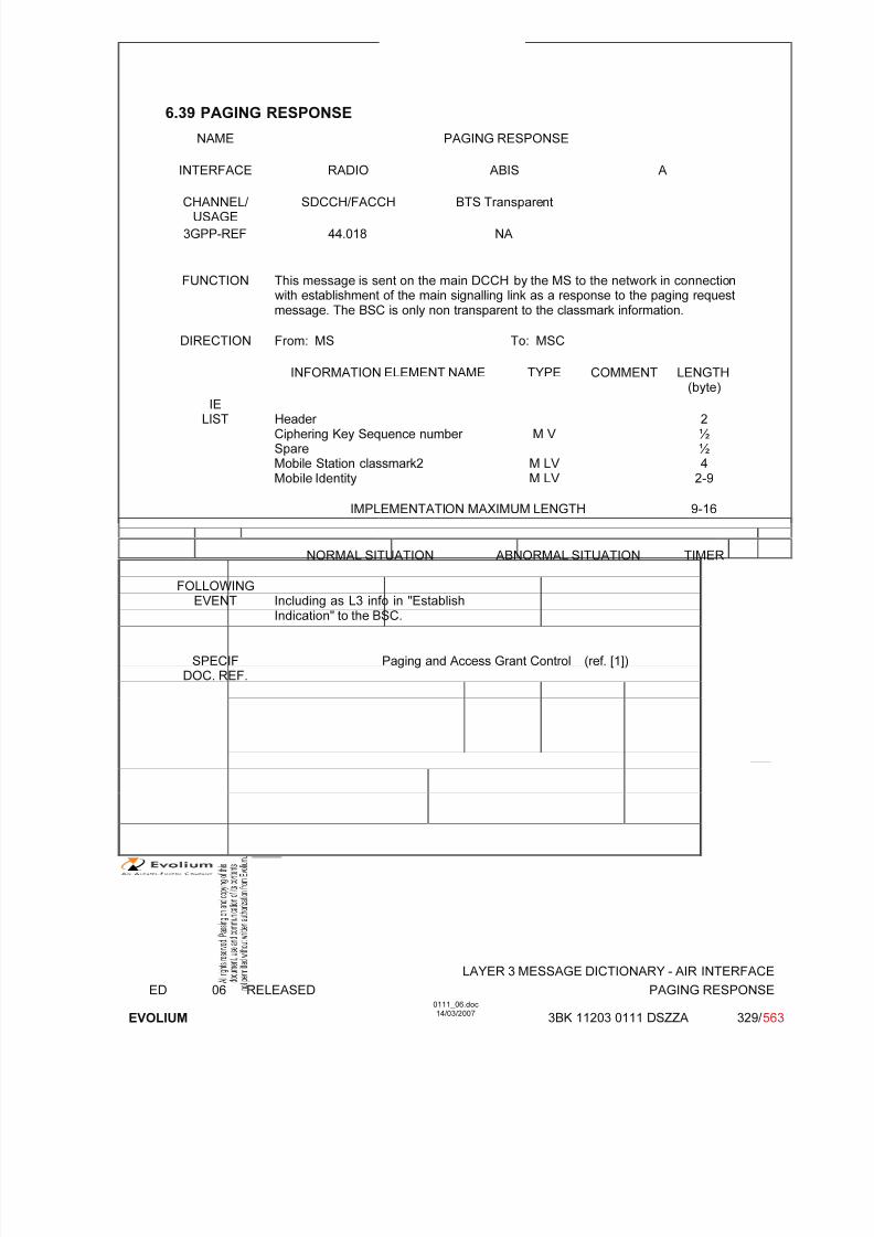
7/11/2019 1. Layer3 Air Interface Messages 0111_06
http://slidepdf.com/reader/full/1-layer3-air-interface-messages-011106 329/562
LAYER 3 MESSAGE DICTIONARY - AIR INTERFACE
ED 06 RELEASED PAGING RESPONSE
EVOLIUM
0111_06.doc14/03/2007
3BK 11203 0111 DSZZA 329/ 563
6.39 PAGING RESPONSE
NAME PAGING RESPONSE
INTERFACE RADIO ABIS A
CHANNEL/ USAGE
SDCCH/FACCH BTS Transparent
3GPP-REF 44.018 NA
FUNCTION This message is sent on the main DCCH by the MS to the network in connection with establishment of the main signalling link as a response to the paging requestmessage. The BSC is only non transparent to the classmark information.
DIRECTION From: MS To: MSC
INFORMATION ELEMENT NAME TYPE COMMENT LENGTH(byte)
IELIST Header
Ciphering Key Sequence number SpareMobile Station classmark2Mobile Identity
M V
M LV M LV
2½½4
2-9
IMPLEMENTATION MAXIMUM LENGTH 9-16
NORMAL SITUATION ABNORMAL SITUATION TIMER
FOLLOWINGEVENT Including as L3 info in "Establish
Indication" to the BSC.
SPECIFDOC. REF.
Paging and Access Grant Control (ref. [1])

7/11/2019 1. Layer3 Air Interface Messages 0111_06
http://slidepdf.com/reader/full/1-layer3-air-interface-messages-011106 330/562
LAYER 3 MESSAGE DICTIONARY - AIR INTERFACE
ED 06 RELEASED PAGING RESPONSE
EVOLIUM
0111_06.doc14/03/2007
3BK 11203 0111 DSZZA 330/ 563
6.39.1 GENERAL DESCRIPTION
Phase 1 MS
8 7 6 5 4 3 2 1
0 0 0 0 0 1 1 0
0 0 1 0 0 1 1 1
spare/ Ciphering Key
0 0 0 0 0 key sequence
Length = 2
Classmark Revisionlevel
EncryptionAlgorithm
RF power Capability
InformationType 2
0 0 0 0 SM.cap
Frequency capability
Length of Mobile Identity contents
Mobile ID digit 1 OEI Type of ID
Identity ID digit 3 ID digit 2
.. .. .. ..
ID Digit p+1 ID Digit p
Phase 2 MS
8 7 6 5 4 3 2 1
0 0 0 0 0 1 1 0
0 0 1 0 0 1 1 1
spare/ Ciphering Key
0 0 0 0 0 key sequence
Length of mobile station classmark 2
Mobile StationClassmark 2
0spare
Revisionlevel
ES-IND A5/1 RF power Capability
0spare
PSCapa.
SS Screen.Indicator
SM.cap
0VBS VGCS
FC
CM3 0spare
LCSVA
CAP
UCS2 SoLSA CMSP A5/3 A5/2
Length of Mobile Identity contents
Mobile ID digit 1 OEI Type of ID
Identity ID digit 3 ID digit 2
.. .. .. ..
ID Digit p+1 ID Digit p

7/11/2019 1. Layer3 Air Interface Messages 0111_06
http://slidepdf.com/reader/full/1-layer3-air-interface-messages-011106 331/562
LAYER 3 MESSAGE DICTIONARY - AIR INTERFACE
ED 06 RELEASED PAGING RESPONSE
EVOLIUM
0111_06.doc14/03/2007
3BK 11203 0111 DSZZA 331/ 563
6.39.2 CIPHERING KEY SEQUENCE NUMBER
TYPE: M
DEFINITIONIdentification of the ciphering key Kc which is stored in the Mobile Station without invoking theauthentification procedure.
BIT DESCRIPTION
8 7 6 5 4 3 2 1
0 key sequence
Bit 4 is spare bit.
SUB PARAMETER DEFINITION
Key sequence: value 0 to 6: Possible values for ciphering key sequence number value 7: no key is available (MS to network)
Reserved (network to MS).
PARAMETER ORIGIN - ACTION ON PARAMETER
BSC is transparent to this parameter.
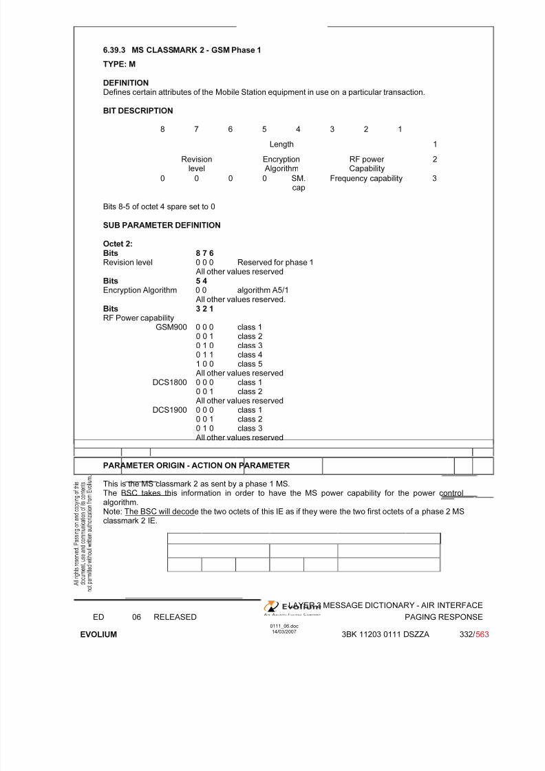
7/11/2019 1. Layer3 Air Interface Messages 0111_06
http://slidepdf.com/reader/full/1-layer3-air-interface-messages-011106 332/562
LAYER 3 MESSAGE DICTIONARY - AIR INTERFACE
ED 06 RELEASED PAGING RESPONSE
EVOLIUM
0111_06.doc14/03/2007
3BK 11203 0111 DSZZA 332/ 563
6.39.3 MS CLASSMARK 2 - GSM Phase 1
TYPE: M
DEFINITION Defines certain attributes of the Mobile Station equipment in use on a particular transaction.
BIT DESCRIPTION
8 7 6 5 4 3 2 1
Length 1
Revisionlevel
EncryptionAlgorithm
RF power Capability
2
0 0 0 0 SM.cap
Frequency capability 3
Bits 8-5 of octet 4 spare set to 0
SUB PARAMETER DEFINITION
Octet 2: Bits 8 7 6Revision level 0 0 0 Reserved for phase 1
All other values reservedBits 5 4Encryption Algorithm 0 0 algorithm A5/1
All other values reserved.Bits 3 2 1RF Power capability
GSM900 0 0 0 class 10 0 1 class 20 1 0 class 3
0 1 1 class 41 0 0 class 5All other values reserved
DCS1800 0 0 0 class 10 0 1 class 2All other values reserved
DCS1900 0 0 0 class 10 0 1 class 20 1 0 class 3All other values reserved
PARAMETER ORIGIN - ACTION ON PARAMETER
This is the MS classmark 2 as sent by a phase 1 MS.The BSC takes this information in order to have the MS power capability for the power controlalgorithm.Note: The BSC will decode the two octets of this IE as if they were the two first octets of a phase 2 MSclassmark 2 IE.
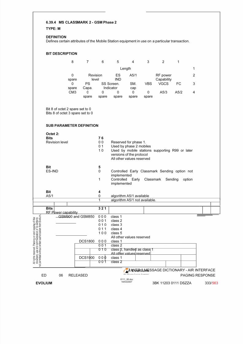
7/11/2019 1. Layer3 Air Interface Messages 0111_06
http://slidepdf.com/reader/full/1-layer3-air-interface-messages-011106 333/562
LAYER 3 MESSAGE DICTIONARY - AIR INTERFACE
ED 06 RELEASED PAGING RESPONSE
EVOLIUM
0111_06.doc14/03/2007
3BK 11203 0111 DSZZA 333/ 563
6.39.4 MS CLASSMARK 2 - GSM Phase 2
TYPE: M
DEFINITIONDefines certain attributes of the Mobile Station equipment in use on a particular transaction.
BIT DESCRIPTION
8 7 6 5 4 3 2 1
Length 1
0spare
Revisionlevel
ESIND
A5/1 RF power Capability
2
0spare
PSCapa.
SS Screen.Indicator
SM.cap
VBS VGCS FC 3
CM3 0spare
0spare
0spare
0spare
0spare
A5/3 A5/2 4
Bit 8 of octet 2 spare set to 0Bits 8 of octet 3 spare set to 0
SUB PARAMETER DEFINITION
Octet 2:Bits 7 6Revision level 0 0 Reserved for phase 1.
0 1 Used by phase 2 mobiles 1 0 Used by mobile stations supporting R99 or later
versions of the protocol
All other values reserved
Bit 5ES-IND 0 Controlled Early Classmark Sending option not
implemented1 Controlled Early Classmark Sending option
implemented
Bit 4A5/1 0 algorithm A5/1 available
1 algorithm A5/1 not available.
Bits 3 2 1
RF Power capabilityGSM900 and GSM850 0 0 0 class 1
0 0 1 class 20 1 0 class 30 1 1 class 41 0 0 class 5
All other values reservedDCS1800 0 0 0 class 1
0 0 1 class 20 1 0 class 3, handled as class 1
All other values reservedDCS1900 0 0 0 class 1
0 0 1 class 2

7/11/2019 1. Layer3 Air Interface Messages 0111_06
http://slidepdf.com/reader/full/1-layer3-air-interface-messages-011106 334/562
LAYER 3 MESSAGE DICTIONARY - AIR INTERFACE
ED 06 RELEASED PAGING RESPONSE
EVOLIUM
0111_06.doc14/03/2007
3BK 11203 0111 DSZZA 334/ 563
0 1 0 class 3, handled as class 1All other values reserved
Octet 3: Bit 7PS Capability 0 PS capability not present
1 PS capability present
Bits 6 5SS Screening Indicator 0 0 Values defined in GSM 04.80
0 1 Values defined in GSM 04.801 0 Values defined in GSM 04.801 1 Values defined in GSM 04.80
Bit 4SM Capability 0 MS does not support mobile terminated point to
point SMS.1 MS supports mobile terminated point to point SMS.
Bit 3
VBS Voice Broadcast Service 0 no VBS capability or no notifications wanted1 VBS capability and notifications wantedNot implemented in the BSS.
Bit 2VGCS Voice Group CallService
0 no VGCS capability or no notifications wanted
1 VGCS capability and notifications wanted
Bit 1FC Frequency Capability
GSM900 0 The MS does not support the extension band G1 in
addition to the primary GSM band.1 The MS does support the extension band G1.
DCS1800, DCS1900 0 Reserved for future use
Octet 4:Bit 8CM3 Classmark 3 0 No additional MS capability
1 Additional MS capabilities are described in theclassmark 3 information element.
Bit 6LCS VA capability 0 LCS value added location request notification
capability not supported1 LCS value added location request notification
capability supportedNot implemented in the BSS.
Bit 5UCS2 treatment 0 the ME has a preference for the default alphabet
(defined in GSM 03.38) over UCS21 the ME has no preference between the use of the
default alphabet and the use of UCS2.Not implemented in the BSS.
Bit 4
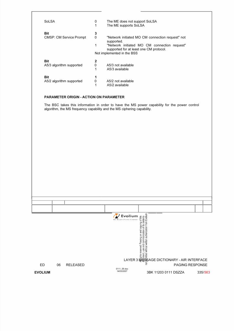
7/11/2019 1. Layer3 Air Interface Messages 0111_06
http://slidepdf.com/reader/full/1-layer3-air-interface-messages-011106 335/562
LAYER 3 MESSAGE DICTIONARY - AIR INTERFACE
ED 06 RELEASED PAGING RESPONSE
EVOLIUM
0111_06.doc14/03/2007
3BK 11203 0111 DSZZA 335/ 563
SoLSA 0 The ME does not support SoLSA1 The ME supports SoLSA
Bit 3CMSP: CM Service Prompt 0 "Network initiated MO CM connection request" not
supported.1 "Network initiated MO CM connection request"
supported for at least one CM protocol.Not implemented in the BSS
Bit 2A5/3 algorithm supported 0 A5/3 not available
1 A5/3 available
Bit 1A5/2 algorithm supported 0 A5/2 not available
1 A5/2 available
PARAMETER ORIGIN - ACTION ON PARAMETER
The BSC takes this information in order to have the MS power capability for the power controlalgorithm, the MS frequency capability and the MS ciphering capability.

7/11/2019 1. Layer3 Air Interface Messages 0111_06
http://slidepdf.com/reader/full/1-layer3-air-interface-messages-011106 336/562
LAYER 3 MESSAGE DICTIONARY - AIR INTERFACE
ED 06 RELEASED PAGING RESPONSE
EVOLIUM
0111_06.doc14/03/2007
3BK 11203 0111 DSZZA 336/ 563
6.39.5 MOBILE IDENTITY
TYPE: M
DEFINITIONTo provide either the IMSI, the TMSI or the IMEI. IMEISV is not used in the Paging request message.
Note IMSI ≤ 15 digitsTMSI = 4 octetsIMEI = 15 digitsIMEISV = 16 digits.
BIT DESCRIPTION
8 7 6 5 4 3 2 1
1 Length of Mobile Identity contents
2 ID digit 1 OEI Type of ID3 ID digit 3 ID digit 2
.. .. .. ..
N ID Digit p+1 ID Digit p
SUB PARAMETER DEFINITION
Type of ID 0 0 1 IMSI0 1 0 IMEI0 1 1 IMEISV 1 0 0 TMSI0 0 0 No Identity (not
used)Other values reserved.
OEI : Odd Even Indicator
value: 0 even number of identity digits (even for TMSI)1 odd number of digits
Filled digit 1 1 1 1
The digit are numerical (0 through 9)(Digit 1 is the most significant)
e.g. IMSI = 1865430 0 0 1 0 1 1 1
Length
0 0 0 1 0 0 0 1
0 1 1 0 1 0 0 0
0 1 0 0 0 1 0 1
1 1 1 1 0 0 1 1
PARAMETER ORIGIN - ACTION ON PARAMETER
7/11/2019 1. Layer3 Air Interface Messages 0111_06
http://slidepdf.com/reader/full/1-layer3-air-interface-messages-011106 337/562
LAYER 3 MESSAGE DICTIONARY - AIR INTERFACE
ED 06 RELEASED PAGING RESPONSE
EVOLIUM
0111_06.doc14/03/2007
3BK 11203 0111 DSZZA 337/ 563
BSC and BTS are transparent to this parameter.
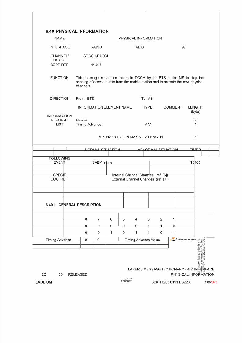
7/11/2019 1. Layer3 Air Interface Messages 0111_06
http://slidepdf.com/reader/full/1-layer3-air-interface-messages-011106 338/562
LAYER 3 MESSAGE DICTIONARY - AIR INTERFACE
ED 06 RELEASED PHYSICAL INFORMATION
EVOLIUM
0111_06.doc14/03/2007
3BK 11203 0111 DSZZA 338/ 563
6.40 PHYSICAL INFORMATION
NAME PHYSICAL INFORMATION
INTERFACE RADIO ABIS A
CHANNEL/ USAGE
SDCCH/FACCH
3GPP-REF 44.018
FUNCTION This message is sent on the main DCCH by the BTS to the MS to stop thesending of access bursts from the mobile station and to activate the new physicalchannels.
DIRECTION From: BTS To: MS
INFORMATION ELEMENT NAME TYPE COMMENT LENGTH(byte)
INFORMATIONELEMENT
LISTHeader Timing Advance M V
21
IMPLEMENTATION MAXIMUM LENGTH 3
NORMAL SITUATION ABNORMAL SITUATION TIMER
FOLLOWINGEVENT SABM frame T3105
SPECIFDOC. REF.
Internal Channel Changes (ref. [6])External Channel Changes (ref. [7])
6.40.1 GENERAL DESCRIPTION
8 7 6 5 4 3 2 1
0 0 0 0 0 1 1 0
0 0 1 0 1 1 0 1
Timing Advance 0 0 Timing Advance Value

7/11/2019 1. Layer3 Air Interface Messages 0111_06
http://slidepdf.com/reader/full/1-layer3-air-interface-messages-011106 339/562
LAYER 3 MESSAGE DICTIONARY - AIR INTERFACE
ED 06 RELEASED PHYSICAL INFORMATION
EVOLIUM
0111_06.doc14/03/2007
3BK 11203 0111 DSZZA 339/ 563
6.40.2 TIMING ADVANCE
TYPE: M
DEFINITIONTo provide Timing Advance value
BIT DESCRIPTION
8 7 6 5 4 3 2 1
0 0 Timing Advance Value
Bits 7, 8 are spare bits.
SUB PARAMETER DEFINITION
Binary representation of the timing advance in bit period(1 bit period 48/13 s).
0: no timing advance (i.e. the MS transmissions to the BS are 468.75 bit periodsbehind)
63: maximum timing advance (The MS transmissions are 405.75 bit periods behind)
PARAMETER ORIGIN - ACTION ON PARAMETER
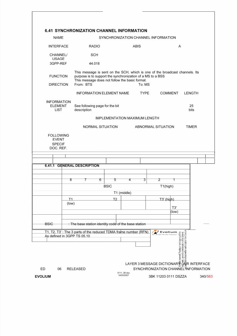
7/11/2019 1. Layer3 Air Interface Messages 0111_06
http://slidepdf.com/reader/full/1-layer3-air-interface-messages-011106 340/562
LAYER 3 MESSAGE DICTIONARY - AIR INTERFACE
ED 06 RELEASED SYNCHRONIZATION CHANNEL INFORMATION
EVOLIUM
0111_06.doc14/03/2007
3BK 11203 0111 DSZZA 340/ 563
6.41 SYNCHRONIZATION CHANNEL INFORMATION
NAME SYNCHRONIZATION CHANNEL INFORMATION
INTERFACE RADIO ABIS A
CHANNEL/ USAGE
SCH
3GPP-REF 44.018
FUNCTIONThis message is sent on the SCH, which is one of the broadcast channels. Itspurpose is to support the synchronization of a MS to a BSSThis message does not follow the basic format.
DIRECTION From: BTS To: MS
INFORMATION ELEMENT NAME TYPE COMMENT LENGTH
INFORMATIONELEMENTLIST
See following page for the bitdescription
25bits
IMPLEMENTATION MAXIMUM LENGTH
NORMAL SITUATION ABNORMAL SITUATION TIMER
FOLLOWINGEVENT
SPECIFDOC. REF.
6.41.1 GENERAL DESCRIPTION
8 7 6 5 4 3 2 1
BSIC T1(high)
T1 (middle)
T1(low)
T2 T3' (high)
T3'(low)
BSIC : The base station identity code of the base station
T1, T2, T3' : The 3 parts of the reduced TDMA frame number (RFN)As defined in 3GPP TS 05.10

7/11/2019 1. Layer3 Air Interface Messages 0111_06
http://slidepdf.com/reader/full/1-layer3-air-interface-messages-011106 341/562
LAYER 3 MESSAGE DICTIONARY - AIR INTERFACE
ED 06 RELEASED SYSTEM INFORMATION TYPE 1
EVOLIUM
0111_06.doc14/03/2007
3BK 11203 0111 DSZZA 341/ 563
6.42 SYSTEM INFORMATION TYPE 1
NAME SYSTEM INFORMATION TYPE 1
INTERFACE RADIO ABIS A
CHANNEL/ USAGE
BCCH
3GPP-REF 44.018
FUNCTION This message is sent on the BCCH by the network to all the Mobile Stations within the cell giving information of control of the RACH and of the cellallocations.
DIRECTION From: BTS To: MS
INFORMATION ELEMENT NAME TYPE COMMENT LENGTH(byte)
INFORMATIONELEMENT
LISTL2 Pseudo LengthHeader Cell Channel descriptionRACH Control parametersSI 1 Rest Octets
M V
M V M V M V
Note 1
121631
IMPLEMENTATION MAXIMUM LENGTH 23
NORMAL SITUATION ABNORMAL SITUATION TIMER
FOLLOWINGEVENT
SPECIFDOC. REF.
BSS Init of Telecom part (ref. [19])Overload Control (ref. [16])
Note (1) Bit map 0 supported for P-GSM onlyVariable bit map supported for DCS 1800, DCS1900 only.
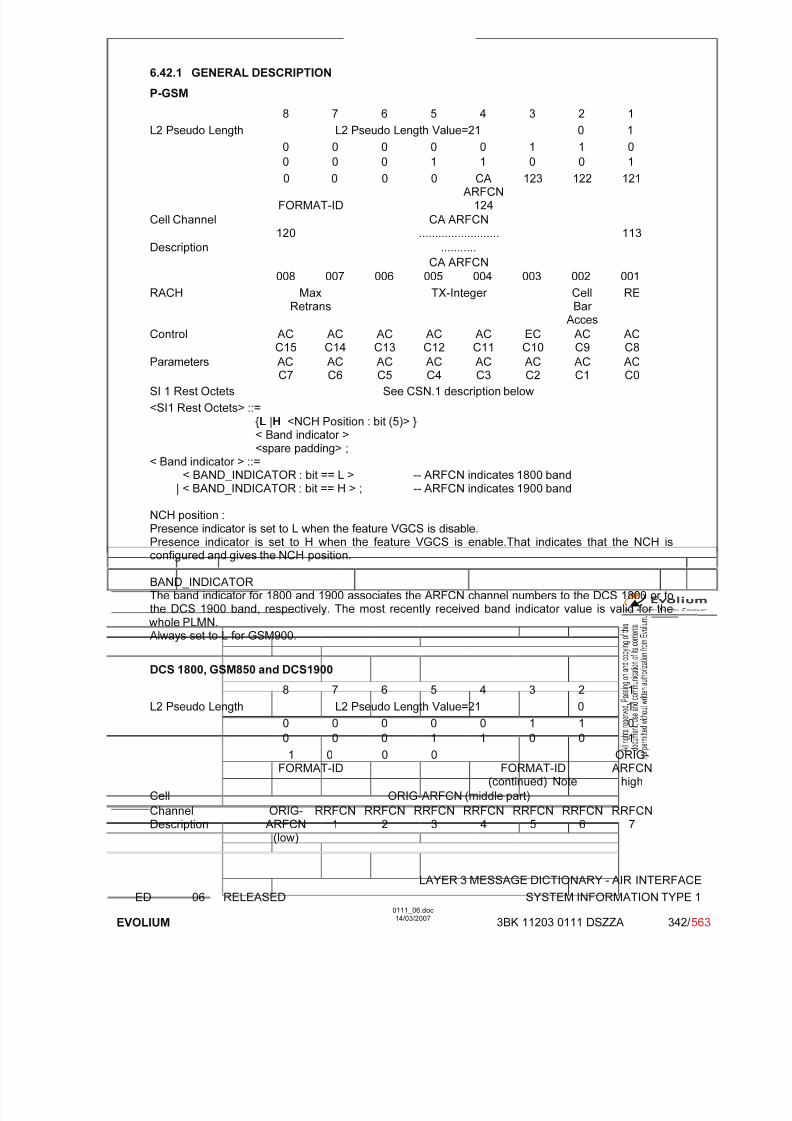
7/11/2019 1. Layer3 Air Interface Messages 0111_06
http://slidepdf.com/reader/full/1-layer3-air-interface-messages-011106 342/562
LAYER 3 MESSAGE DICTIONARY - AIR INTERFACE
ED 06 RELEASED SYSTEM INFORMATION TYPE 1
EVOLIUM
0111_06.doc14/03/2007
3BK 11203 0111 DSZZA 342/ 563
6.42.1 GENERAL DESCRIPTION
P-GSM
8 7 6 5 4 3 2 1
L2 Pseudo Length L2 Pseudo Length Value=21 0 1
0 0 0 0 0 1 1 0
0 0 0 1 1 0 0 1
0 0
FORMAT-ID
0 0 CAARFCN
124
123 122 121
Cell Channel120
CA ARFCN......................... 113
Description ...........
CA ARFCN
008 007 006 005 004 003 002 001
RACH MaxRetrans
TX-Integer CellBar
Acces
RE
Control AC
C15
AC
C14
AC
C13
AC
C12
AC
C11
EC
C10
AC
C9
AC
C8Parameters AC
C7ACC6
ACC5
ACC4
ACC3
ACC2
ACC1
ACC0
SI 1 Rest Octets See CSN.1 description below
<SI1 Rest Octets> ::={L |H <NCH Position : bit (5)> }< Band indicator ><spare padding> ;
< Band indicator > ::=< BAND_INDICATOR : bit == L > -- ARFCN indicates 1800 band
| < BAND_INDICATOR : bit == H > ; -- ARFCN indicates 1900 band
NCH position :Presence indicator is set to L when the feature VGCS is disable.Presence indicator is set to H when the feature VGCS is enable.That indicates that the NCH isconfigured and gives the NCH position.
BAND_INDICATORThe band indicator for 1800 and 1900 associates the ARFCN channel numbers to the DCS 1800 or tothe DCS 1900 band, respectively. The most recently received band indicator value is valid for the whole PLMN.Always set to L for GSM900.
DCS 1800, GSM850 and DCS1900
8 7 6 5 4 3 2 1L2 Pseudo Length L2 Pseudo Length Value=21 0 1
0 0 0 0 0 1 1 0
0 0 0 1 1 0 0 1
1 0FORMAT-ID
0 0FORMAT-ID
(continued) Note
ORIG-ARFCN
high
Cell ORIG-ARFCN (middle part)
ChannelDescription
ORIG-ARFCN
(low)
RRFCN1
RRFCN2
RRFCN3
RRFCN4
RRFCN5
RRFCN6
RRFCN7

7/11/2019 1. Layer3 Air Interface Messages 0111_06
http://slidepdf.com/reader/full/1-layer3-air-interface-messages-011106 343/562
LAYER 3 MESSAGE DICTIONARY - AIR INTERFACE
ED 06 RELEASED SYSTEM INFORMATION TYPE 1
EVOLIUM
0111_06.doc14/03/2007
3BK 11203 0111 DSZZA 343/ 563
::
::
RRFCN104
RRFCN105
RRFCN106
RRFCN107
RRFCN108
RRFCN109
RRFCN110
RRFCN111
RACH MaxRetrans
TX-Integer CellBar
Acces
RE
Control ACC15
ACC14
ACC13
ACC12
ACC11
ECC10
ACC9
ACC8
Parameters ACC7
ACC6
ACC5
ACC4
ACC3
ACC2
ACC1
ACC0
SI 1 Rest Octets See CSN.1 description below.
<SI1 Rest Octets> ::={L |H <NCH Position : bit (5)> }< Band indicator ><spare padding> ;
< Band indicator > ::=< BAND_INDICATOR : bit == L > -- ARFCN indicates 1800 band
| < BAND_INDICATOR : bit == H > ; -- ARFCN indicates 1900 band
NCH position :Presence indicator is set to L when the feature VGCS is disable.Presence indicator is set to H when the feature VGCS is enable.That indicates that the NCH isconfigured and gives the NCH position.
BAND_INDICATORThe band indicator for 1800 and 1900 associates the ARFCN channel numbers to the DCS 1800 or tothe DCS 1900 band, respectively. The most recently received band indicator value is valid for the whole PLMN.
If the PLMN_FREQUENCY_BANDS is set to GSM850 – DCS1900, then the BAND_INDICATOR isset to HIGH, else set to .LOW.
Note: 0 x x: Range 1024 format;1 0 0: Range 512 format;1 0 1: Range 256 format;1 1 0: Range 128 format;1 1 1: Variable bit map.
6.42.2 CELL CHANNEL DESCRIPTION
TYPE: M
DEFINITIONTo provide the absolute radio frequency channel numbers used in a cell (belonging to thesame band (P-GSM, GSM850, DCS1800, DCS1900) as the BCCH).
BIT DESCRIPTION
Bit map 0 (P-GSM)8 7 6 5 4 3 2 1
0 0FORMAT-ID
0 0 124CA
ARFCN
123 122 121
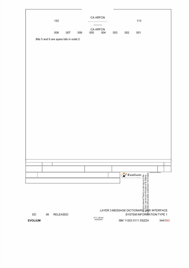
7/11/2019 1. Layer3 Air Interface Messages 0111_06
http://slidepdf.com/reader/full/1-layer3-air-interface-messages-011106 344/562
LAYER 3 MESSAGE DICTIONARY - AIR INTERFACE
ED 06 RELEASED SYSTEM INFORMATION TYPE 1
EVOLIUM
0111_06.doc14/03/2007
3BK 11203 0111 DSZZA 344/ 563
120CA ARFCN
......................... 113
...........
CA ARFCN008 007 006 005 004 003 002 001
Bits 5 and 6 are spare bits in octet 2.

7/11/2019 1. Layer3 Air Interface Messages 0111_06
http://slidepdf.com/reader/full/1-layer3-air-interface-messages-011106 345/562
LAYER 3 MESSAGE DICTIONARY - AIR INTERFACE
ED 06 RELEASED SYSTEM INFORMATION TYPE 1
EVOLIUM
0111_06.doc14/03/2007
3BK 11203 0111 DSZZA 345/ 563
Range 1024 format supported
8 7 6 5 4 3 2 1
1 0FORMAT-ID
0spare
0spare
0FORM-
ID
F0 W(1) (high part) 1
W(1) (low part) 2
W(2) (high part) 3
W(2)(low)
W(3) (high part) 4
W(3) (low part) W(4) (high part) 5
W(4) (low part) W(5) (high part) 6
W(5) (low part) W(6) (high part) 7
W(6) (low part) W(7) (high part) 8
W(7) (low part) W(8) (high part) 9
W(8)(low)
W(9) 10
W(10) W(11)(high)
11
W(11) (low part) W(12) (high part) 12
W(12) (low part) W(13) (high part) 13
W(13) (low part) W(14) (high part) 14
W(14) (low part) W(15) (high part) 15
W(15) (low part) W(16) 16
SUB PARAMETER DEFINITION
FORMAT-ID : Format identifier.
F0 : Frequency indicator 0 ARFCN 0 is not a member of the set1 ARFCN 0 is a member of the set
W(i) : Each W(i) encodes a non negative integer in binary.if W(k) is null, W(K+1) to W(16) must be null also.

7/11/2019 1. Layer3 Air Interface Messages 0111_06
http://slidepdf.com/reader/full/1-layer3-air-interface-messages-011106 346/562
LAYER 3 MESSAGE DICTIONARY - AIR INTERFACE
ED 06 RELEASED SYSTEM INFORMATION TYPE 1
EVOLIUM
0111_06.doc14/03/2007
3BK 11203 0111 DSZZA 346/ 563
Range 512 format supported
8 7 6 5 4 3 2 1
1 0FORMAT-ID
0spare
0spare
1 0 0FORM-ID
ORIG-ARFCN
high
1
ORIG-ARFCN (middle part) 2
ORIG-ARFCN
low
W(1) (high part) 3
W(1) (low part) W(2) (high part) 4
W(2) (low) W(3) (high part) 5
W(3) (low part) W(4) (high part) 6
W(4)(low)
W(5) 7
W(6) W(7)(high)
8
W(7) (low part) W(8) (high part) 9
W(8) (low part) W(9) (high part) 10
W(9) (low part) W(10) 11
W(11) W(12) (high) 12
W(12) (low part) W(13) (high part) 13
W(13) (low part) W(14) 14
W(15) W(16) (high) 15
W(16) (low part) W(17) 16
SUB PARAMETER DEFINITION
FORMAT-ID : Format identifier.
ORIG-ARFCN : This field encodes the ARFCN of one frequency belonging to the set. This value isalso used to decode the rest of the element.
W(i) : Each W(i) encodes a non negative integer in binary.if W(k) is null, W(K+1) to W(17) must be null also.

7/11/2019 1. Layer3 Air Interface Messages 0111_06
http://slidepdf.com/reader/full/1-layer3-air-interface-messages-011106 347/562
LAYER 3 MESSAGE DICTIONARY - AIR INTERFACE
ED 06 RELEASED SYSTEM INFORMATION TYPE 1
EVOLIUM
0111_06.doc14/03/2007
3BK 11203 0111 DSZZA 347/ 563
Range 256 format supported
8 7 6 5 4 3 2 1
1 0FORMAT-ID
0spare
0spare
1 0 1FORM-ID
ORIG-ARFCN
high
1
ORIG-ARFCN (middle part) 2
ORIG-ARFCN
low
W(1) (high part) 3
W(1)(loW)
W(2) 4
W(3) W(4)(high)
5
W(4) (low part) W(5) (high part) 6
W(5) (low part) W(6) (high part) 7
W(6)(low)
W(7) W(8)(high)
8
W(8) (low part) W(9) (high part) 9
W(9)(low)
W(10) W(11) (high) 10
W(11) (low part) W(12) 11
W(13) W(14) (high part) 12
W(14) (low part) W(15) W(16)(high)
13
W(16) (low part) W(17) W(18)(high)
14
W(18) (low part) W(19) W(20)(high)
15
W(20) (low part) W(21) 0spare
16
SUB PARAMETER DEFINITION
FORMAT-ID : Format identifier.
ORIG-ARFCN : This field encodes the ARFCN of one frequency belonging to the set. This value isalso used to decode the rest of the element.
W(i) : Each W(i) encodes a non negative integer in binary.if W(k) is null, W(K+1) to W(21) must be null also.

7/11/2019 1. Layer3 Air Interface Messages 0111_06
http://slidepdf.com/reader/full/1-layer3-air-interface-messages-011106 348/562
LAYER 3 MESSAGE DICTIONARY - AIR INTERFACE
ED 06 RELEASED SYSTEM INFORMATION TYPE 1
EVOLIUM
0111_06.doc14/03/2007
3BK 11203 0111 DSZZA 348/ 563
Range 128 format supported
8 7 6 5 4 3 2 1
1 0FORMAT-ID
0spare
0spare
1 1 0FORM-ID
ORIG-ARFCN
high
1
ORIG-ARFCN (middle part) 2
ORIG-ARFCN
low
W(1) 3
W(2) W(3) (high part) 4
W(3) (low part) W(4) (high part) 5
W(4)(low)
W(5) W(6) (high part) 6
W(6) (low part) W(7) 7
W(8) W(9) 8
W(10) W(11) 9
W(12) W(13) 10
W(14) W(15) 11
W(16) W(17) W(18) (high) 12
W(18)(low)
W(19) W(20) W(21)(high)
13
W(21) (low) W(22) W(23) 14
W(24) W(25) W(26) (high) 15
W(26)(low)
W(27) W(28) 0spare
16
SUB PARAMETER DEFINITION
FORMAT-ID : Format identifier.
ORIG-ARFCN : This field encodes the ARFCN of one frequency belonging to the set. This value isalso used to decode the rest of the element.
W(i) : Each W(i) encodes a non negative integer in binary.if W(k) is null, W(K+1) to W(28) must be null also.

7/11/2019 1. Layer3 Air Interface Messages 0111_06
http://slidepdf.com/reader/full/1-layer3-air-interface-messages-011106 349/562
LAYER 3 MESSAGE DICTIONARY - AIR INTERFACE
ED 06 RELEASED SYSTEM INFORMATION TYPE 1
EVOLIUM
0111_06.doc14/03/2007
3BK 11203 0111 DSZZA 349/ 563
Variable bit map format supported
8 7 6 5 4 3 2 1
1 0FORMAT-ID
0 0 1 1 1FORMAT-ID(continued)
ORIG-ARFC
N
highORIG-ARFCN (middle part)
ORIG-ARFCN
(low)
RRFCN1
RRFCN2
RRFCN3
RRFCN4
RRFCN5
RRFCN6
RRFCN7
: :
RRFCN104
RRFCN105
RRFCN106
RRFCN107
RRFCN108
RRFCN109
RRFCN110
RRFCN
111
Bits 5 and 6 are spare bits in octet 2.
SUB PARAMETER DEFINITION
FORMAT-ID : Format identifier Bitmap 0 format is only supported for GSM 900Variable bit map is only supported for DCS 1800, GSM850 andDCS1900
CA ARFCN N : Cell Allocation Absolute Radio Frequency Channel Number N
CA ARFCN N : "0" not belonging to the cell allocation"1" belonging to the cell allocation
ORIG-ARFCN : This field encodes the ARFCN of one frequency belonging to the set. This value isalso used as the origin of the bit map to generate all the other frequencies.
RRFCN N : Relative radio frequency channel number N- For an RF channel with ARFCN = ORIG-ARFCN + N) mod 1024 belonging to the set,
then RRFCN N bit is coded as '1'.- For an RF channel with ARFCN = (ORIG-ARFCN + N) mod 1024 not belonging to the set,
then RRFCN N bit is coded as '0'.
PARAMETER ORIGIN - ACTION ON PARAMETER
CA ARFCN N, ORIG-ARFCN, RRFCN : values stored in BSC and updated according to systemreconfigurations.

7/11/2019 1. Layer3 Air Interface Messages 0111_06
http://slidepdf.com/reader/full/1-layer3-air-interface-messages-011106 350/562
LAYER 3 MESSAGE DICTIONARY - AIR INTERFACE
ED 06 RELEASED SYSTEM INFORMATION TYPE 1
EVOLIUM
0111_06.doc14/03/2007
3BK 11203 0111 DSZZA 350/ 563
6.42.3 RACH CONTROL PARAMETERS
TYPE: M
DEFINITIONTo provide parameters used to control the RACH utilisation.
BIT DESCRIPTION
8 7 6 5 4 3 2 1
MaxRetrans
TX-Integer CellBar
Acces
RE
ACC15
ACC14
ACC13
ACC12
ACC11
ECC10
ACC09
ACC08
ACC07
ACC06
ACC05
ACC04
ACC03
ACC02
ACC01
ACC00
SUB PARAMETER DEFINITION
Max Retrans 00 1 re transmission01 2 re transmissions10 4 re transmissions11 7 re transmissions
TX Integer Number of time slots to spread transmission
Bits 6 5 4 3
0 0 0 0 3 slots used to spread transmission0 0 0 1 4 slots used to spread transmission0 0 1 0 5 slots used to spread transmission0 0 1 1 6 slots used to spread transmission0 1 0 0 7 slots used to spread transmission0 1 0 1 8 slots used to spread transmission0 1 1 0 9 slots used to spread transmission0 1 1 1 10 slots used to spread transmission1 0 0 0 11 slots used to spread transmission1 0 0 1 12 slots used to spread transmission1 0 1 0 14 slots used to spread transmission1 0 1 1 16 slots used to spread transmission1 1 0 0 20 slots used to spread transmission1 1 0 1 25 slots used to spread transmission1 1 1 0 32 slots used to spread transmission1 1 1 1 50 slots used to spread transmission
Cell Bar Access: Cell barred for access0: the cell is not barred.1: the cell is barred.
RE Call Re-establishment allowed0: Re-establishment allowed in the cell1: Re-establishment not allowed in the cell
EC Emergency Call allowed (Octet 3 bit 3)

7/11/2019 1. Layer3 Air Interface Messages 0111_06
http://slidepdf.com/reader/full/1-layer3-air-interface-messages-011106 351/562
LAYER 3 MESSAGE DICTIONARY - AIR INTERFACE
ED 06 RELEASED SYSTEM INFORMATION TYPE 1
EVOLIUM
0111_06.doc14/03/2007
3BK 11203 0111 DSZZA 351/ 563
0: Emergency Call allowed in the cell to all MSs1: Emergency Call not allowed in the cell except for the MSs that belong to one of the classes
between 11 to 15
AC CN : Access Control Class N (octet 3 except bit 3) and octet 4.
For a mobile station with AC CN, access is not barred
if the AC CN bit is coded with "0" ; N = 0,1..9,11..15.
PARAMETER ORIGIN - ACTION ON PARAMETER
All the parameters are given to BSC during configuration and may be changed with OMC requests or by BSC due to "Overload" or "Reset" actions.
6.42.4 SI 1 REST OCTETS
TYPE: M
DEFINITIONThis parameter consists of either spare bits or gives the NCH Position depending if the featureVGCS is enable or not only .It is used to allow the introduction of new information on theBCCH in later phases.
BIT DESCRIPTION
EN_VGCS = False
8 7 6 5 4 3 2 1
0(Low)
BandIndicator
1Spare
0Spare
1Spare
0Spare
1Spare
1Spare
EN_VGCS = True
8 7 6 5 4 3 2 1
1(High)
NCH Position BandIndicato
r
1Spare
SUB PARAMETER DEFINITION
Band Indicator : The band indicator for DCS1800 or DCS1900 associates the ARFCN channelnumbers to the DCS 1800 band, or to the DCS 1900 band respectively (see 3GPPTS 05.05). The most recently received band indicator value is valid for the wholePLMN.
0 ARFCN indicates 1800 band
1 ARFCN indicates 1900 band (not supported)

7/11/2019 1. Layer3 Air Interface Messages 0111_06
http://slidepdf.com/reader/full/1-layer3-air-interface-messages-011106 352/562
LAYER 3 MESSAGE DICTIONARY - AIR INTERFACE
ED 06 RELEASED SYSTEM INFORMATION TYPE 1
EVOLIUM
0111_06.doc14/03/2007
3BK 11203 0111 DSZZA 352/ 563
NCH Position on the CCCH: The values in the NCH Position field indicates the block number of theCCCH block which is used for the first NCH block and the number of blocks used for the NCH. The following coding applies if 1 or more basic physical channels are usedfor CCCH, not combined with SDCCHs.
Value No of blocks Number of first block
0 0 0 0 0 1 00 0 0 0 1 1 10 0 0 1 0 1 20 0 0 1 1 1 30 0 1 0 0 1 40 0 1 0 1 1 50 0 1 1 0 1 60 0 1 1 1 2 00 1 0 0 0 2 10 1 0 0 1 2 20 1 0 1 0 2 30 1 0 1 1 2 40 1 1 0 0 2 5
0 1 1 0 1 3 00 1 1 1 0 3 10 1 1 1 1 3 21 0 0 0 0 3 31 0 0 0 1 3 41 0 0 1 0 4 01 0 0 1 1 4 11 0 1 0 0 4 21 0 1 0 1 4 31 0 1 1 0 5 01 0 1 1 1 5 11 1 0 0 0 5 21 1 0 0 1 6 0
1 1 0 1 0 6 11 1 0 1 1 7 0
PARAMETER ORIGIN - ACTION ON PARAMETER

7/11/2019 1. Layer3 Air Interface Messages 0111_06
http://slidepdf.com/reader/full/1-layer3-air-interface-messages-011106 353/562
LAYER 3 MESSAGE DICTIONARY - AIR INTERFACE
ED 06 RELEASED SYSTEM INFORMATION TYPE 2
EVOLIUM
0111_06.doc14/03/2007
3BK 11203 0111 DSZZA 353/ 563
6.43 SYSTEM INFORMATION TYPE 2
NAME SYSTEM INFORMATION TYPE 2
INTERFACE RADIO ABIS A
CHANNEL/ USAGE
BCCH
3GPP-REF 44.018
FUNCTION This message is sent on the BCCH by the network to stations within the cellgiving information of control of the RACH and the BCCH allocation in theneighbour cells.
DIRECTION From: BTS To: MS
INFORMATION ELEMENT NAME TYPE COMMENT LENGTH(byte)
INFORMATIONELEMENT
LISTL2 Pseudo LengthHeader BCCH Frequency ListNCC permittedRACH Control parameters
M V M V M V M V M V
121613
IMPLEMENTATION MAXIMUM LENGTH 23
NORMAL SITUATION ABNORMAL SITUATION TIMER
FOLLOWINGEVENT
SPECIFDOC. REF.
BSS Init of Telecom part (ref. [19])Overload Control (ref. [16])

7/11/2019 1. Layer3 Air Interface Messages 0111_06
http://slidepdf.com/reader/full/1-layer3-air-interface-messages-011106 354/562
LAYER 3 MESSAGE DICTIONARY - AIR INTERFACE
ED 06 RELEASED SYSTEM INFORMATION TYPE 2
EVOLIUM
0111_06.doc14/03/2007
3BK 11203 0111 DSZZA 354/ 563
6.43.1 GENERAL DESCRIPTION
P-GSM8 7 6 5 4 3 2 1
L2 Pseudo Length L2 Pseudo Length Value=22 0 1
0 0 0 0 0 1 1 0
0 0 0 1 1 0 1 0Neighbour
0 0
EXT-IND
0
BA-IND0
BAARFCN
124
BAARFCN
123
BAARFCN
122
BAARFCN
121
Cell BAARFCN
120
BAARFCN
119
BAARFCN
118
BAARFCN
117
BAARFCN
116
BAARFCN
115
BAARFCN
114
BAARFCN
113
Description ................
BAARFCN
008
BAARFCN
007
BAARFCN
006
BAARFCN
005
BAARFCN
004
BAARFCN
003
BAARFCN
002
BAARFCN
001
NCC Permitted NCC permitted
RACH MaxRetrans TX-Integer CellBar Acces
RE
Control ACC15
ACC14
ACC13
ACC12
ACC11
ECC10
ACC9
ACC8
Parameters ACC7
ACC6
ACC5
ACC4
ACC3
ACC2
ACC1
ACC0
E-GSM, DCS 1800, DCS1900, GSM850 and Biband8 7 6 5 4 3 2 1
L2 Pseudo Length L2 Pseudo Length Value=22 0 1
0 0 0 0 0 1 1 0
0 0 0 1 1 0 1 0
1 0FORMAT-ID
EXT-IND
BA-INDFORMAT-ID
(continued) Note
ORIG-ARFCN
high
Neighbour ORIG-ARFCN (middle part)
CellDescription
ORIG-ARFCN
(low)
RRFCN1
RRFCN2
RRFCN3
RRFCN4
RRFCN5
RRFCN6
RRFCN7
::
::
RRFCN104
RRFCN105
RRFCN106
RRFCN107
RRFCN108
RRFCN109
RRFCN110
RRFCN111
NCC Permitted NCC permitted
RACH MaxRetrans
TX-Integer CellBar
Acces
RE
Control ACC15
ACC14
ACC13
ACC12
ACC11
ECC10
ACC9
ACC8
Parameters ACC7
ACC6
ACC5
ACC4
ACC3
ACC2
ACC1
ACC0
Note: 0 x x: Range 1024 format;1 0 0: Range 512 format;1 0 1: Range 256 format;1 1 0: Range 128 format;1 1 1: Variable bit map.
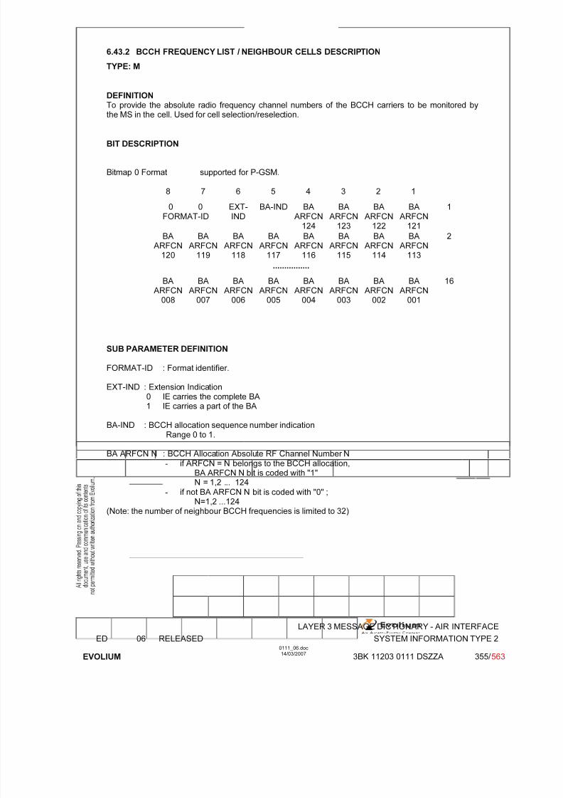
7/11/2019 1. Layer3 Air Interface Messages 0111_06
http://slidepdf.com/reader/full/1-layer3-air-interface-messages-011106 355/562
LAYER 3 MESSAGE DICTIONARY - AIR INTERFACE
ED 06 RELEASED SYSTEM INFORMATION TYPE 2
EVOLIUM
0111_06.doc14/03/2007
3BK 11203 0111 DSZZA 355/ 563
6.43.2 BCCH FREQUENCY LIST / NEIGHBOUR CELLS DESCRIPTION
TYPE: M
DEFINITIONTo provide the absolute radio frequency channel numbers of the BCCH carriers to be monitored bythe MS in the cell. Used for cell selection/reselection.
BIT DESCRIPTION
Bitmap 0 Format supported for P-GSM.
8 7 6 5 4 3 2 1
0 0FORMAT-ID
EXT-IND
BA-IND BAARFCN
124
BAARFCN
123
BAARFCN
122
BAARFCN
121
1
BA
ARFCN120
BA
ARFCN119
BA
ARFCN118
BA
ARFCN117
BA
ARFCN116
BA
ARFCN115
BA
ARFCN114
BA
ARFCN113
2
................
BAARFCN
008
BAARFCN
007
BAARFCN
006
BAARFCN
005
BAARFCN
004
BAARFCN
003
BAARFCN
002
BAARFCN
001
16
SUB PARAMETER DEFINITION
FORMAT-ID : Format identifier.
EXT-IND : Extension Indication0 IE carries the complete BA1 IE carries a part of the BA
BA-IND : BCCH allocation sequence number indicationRange 0 to 1.
BA ARFCN N : BCCH Allocation Absolute RF Channel Number N- if ARFCN = N belongs to the BCCH allocation,
BA ARFCN N bit is coded with "1"N = 1,2 ... 124
- if not BA ARFCN N bit is coded with "0" ;N=1,2 ...124
(Note: the number of neighbour BCCH frequencies is limited to 32)

7/11/2019 1. Layer3 Air Interface Messages 0111_06
http://slidepdf.com/reader/full/1-layer3-air-interface-messages-011106 356/562
LAYER 3 MESSAGE DICTIONARY - AIR INTERFACE
ED 06 RELEASED SYSTEM INFORMATION TYPE 2
EVOLIUM
0111_06.doc14/03/2007
3BK 11203 0111 DSZZA 356/ 563
Range 1024 format supported
8 7 6 5 4 3 2 1
1 0FORMAT-ID
EXT-IND
BA-IND 0FORM-ID
F0 W(1) (high part) 1
W(1) (low part) 2
W(2) (high part) 3
W(2)(low)
W(3) (high part) 4
W(3) (low part) W(4) (high part) 5
W(4) (low part) W(5) (high part) 6
W(5) (low part) W(6) (high part) 7
W(6) (low part) W(7) (high part) 8
W(7) (low part) W(8) (high part) 9
W(8)
(low)
W(9) 10
W(10) W(11)(high)
11
W(11) (low part) W(12) (high part) 12
W(12) (low part) W(13) (high part) 13
W(13) (low part) W(14) (high part) 14
W(14) (low part) W(15) (high part) 15
W(15) (low part) W(16) 16
SUB PARAMETER DEFINITION
FORMAT-ID : Format identifier.
EXT-IND : Extension Indication0 IE carries the complete BA1 IE carries a part of the BA
BA-IND : BCCH allocation sequence number indicationRange 0 to 1.
F0 : Frequency indicator 0 ARFCN 0 is not a member of the set1 ARFCN 0 is a member of the set
W(i) : Each W(i) encodes a non negative integer in binary.if W(k) is null, W(K+1) to W(16) must be null also.

7/11/2019 1. Layer3 Air Interface Messages 0111_06
http://slidepdf.com/reader/full/1-layer3-air-interface-messages-011106 357/562
LAYER 3 MESSAGE DICTIONARY - AIR INTERFACE
ED 06 RELEASED SYSTEM INFORMATION TYPE 2
EVOLIUM
0111_06.doc14/03/2007
3BK 11203 0111 DSZZA 357/ 563
Range 512 format supported
8 7 6 5 4 3 2 1
1 0FORMAT-ID
EXT-IND
BA-IND 1 0 0FORMAT-ID (cont)
ORIG-ARFCN
1
ORIG-ARFCN (middle part) 2
ORIG-ARFCN
W(1) (high part) 3
W(1) (low part) W(2) (high part) 4
W(2) (low) W(3) (high part) 5
W(3) (low part) W(4) (high part) 6
W(4)(low)
W(5) 7
W(6) W(7)(high)
8
W(7) (low part) W(8) (high part) 9
W(8) (low part) W(9) (high part) 10
W(9) (low part) W(10) 11
W(11) W(12) (high) 12
W(12) (low part) W(13) (high part) 13
W(13) (low part) W(14) 14
W(15) W(16) (high) 15
W(16) (low part) W(17) 16
SUB PARAMETER DEFINITION
FORMAT-ID : Format identifier.
EXT-IND : Extension Indication0 IE carries the complete BA1 IE carries a part of the BA
BA-IND : BCCH allocation sequence number indicationRange 0 to 1.
ORIG-ARFCN : This field encodes the ARFCN of one frequency belonging to the set. This value isalso used as the origin of the bit map to generate all the other frequencies.
W(i) : Each W(i) encodes a non negative integer in binary.if W(k) is null, W(K+1) to W(17) must be null also.

7/11/2019 1. Layer3 Air Interface Messages 0111_06
http://slidepdf.com/reader/full/1-layer3-air-interface-messages-011106 358/562
LAYER 3 MESSAGE DICTIONARY - AIR INTERFACE
ED 06 RELEASED SYSTEM INFORMATION TYPE 2
EVOLIUM
0111_06.doc14/03/2007
3BK 11203 0111 DSZZA 358/ 563
Range 256 format supported
8 7 6 5 4 3 2 1
1 0FORMAT-ID
EXT-IND
BA-IND 1 0 1FORMAT-ID (cont)
ORIG-ARFCN
1
ORIG-ARFCN (middle part) 2
ORIG-ARFCN
W(1) (high part) 3
W(1)(loW)
W(2) 4
W(3) W(4)(high)
5
W(4) (low part) W(5) (high part) 6
W(5) (low part) W(6) (high part) 7
W(6)(low)
W(7) W(8)(high)
8
W(8) (low part) W(9) (high part) 9
W(9)(low)
W(10) W(11) (high) 10
W(11) (low part) W(12) 11
W(13) W(14) (high part) 12
W(14) (low part) W(15) W(16)(high)
13
W(16) (low part) W(17) W(18)(high)
14
W(18) (low part) W(19) W(20)(high)
15
W(20) (low part) W(21) 0
spare
16
SUB PARAMETER DEFINITION
FORMAT-ID : Format identifier.
EXT-IND : Extension Indication0 IE carries the complete BA1 IE carries a part of the BA
BA-IND : BCCH allocation sequence number indicationRange 0 to 1.
ORIG-ARFCN : This field encodes the ARFCN of one frequency belonging to the set. This value isalso used as the origin of the bit map to generate all the other frequencies.
W(i) : Each W(i) encodes a non negative integer in binary.if W(k) is null, W(K+1) to W(21) must be null also.

7/11/2019 1. Layer3 Air Interface Messages 0111_06
http://slidepdf.com/reader/full/1-layer3-air-interface-messages-011106 359/562
LAYER 3 MESSAGE DICTIONARY - AIR INTERFACE
ED 06 RELEASED SYSTEM INFORMATION TYPE 2
EVOLIUM
0111_06.doc14/03/2007
3BK 11203 0111 DSZZA 359/ 563
Range 128 format supported
8 7 6 5 4 3 2 1
1 0FORMAT-ID
EXT-IND
BA-IND 1 1 1FORMAT-ID (cont)
ORIG-ARFCN
1
ORIG-ARFCN (middle part) 2
ORIG-ARFCN
W(1) 3
W(2) W(3) (high part) 4
W(3) (low part) W(4) (high part) 5
W(4)(low)
W(5) W(6) (high part) 6
W(6) (low part) W(7) 7
W(8) W(9) 8
W(10) W(11) 9
W(12) W(13) 10
W(14) W(15) 11
W(16) W(17) W(18) (high) 12
W(18)(low)
W(19) W(20) W(21)(high)
13
W(21) (low) W(22) W(23) 14
W(24) W(25) W(26) (high) 15
W(26)(low)
W(27) W(28) 0spare
16
SUB PARAMETER DEFINITION
FORMAT-ID : Format identifier.
EXT-IND : Extension Indication0 IE carries the complete BA1 IE carries a part of the BA
BA-IND : BCCH allocation sequence number indicationRange 0 to 1.
ORIG-ARFCN : This field encodes the ARFCN of one frequency belonging to the set. This value isalso used as the origin of the bit map to generate all the other frequencies.
W(i) : Each W(i) encodes a non negative integer in binary.if W(k) is null, W(K+1) to W(28) must be null also.

7/11/2019 1. Layer3 Air Interface Messages 0111_06
http://slidepdf.com/reader/full/1-layer3-air-interface-messages-011106 360/562
LAYER 3 MESSAGE DICTIONARY - AIR INTERFACE
ED 06 RELEASED SYSTEM INFORMATION TYPE 2
EVOLIUM
0111_06.doc14/03/2007
3BK 11203 0111 DSZZA 360/ 563
Variable Bit Map format supported
8 7 6 5 4 3 2 1
1 0FORMAT-ID
EXT-IND
BA-IND 1 1 1FORMAT-ID(continued)
ORIG-ARFCN
high
1
ORIG-ARFCN (middle part) 2
ORIG-ARFCN
(low)
RRFCN1
RRFCN2
RRFCN3
RRFCN4
RRFCN5
RRFCN6
RRFCN7
: :
RRFCN104
RRFCN105
RRFCN106
RRFCN107
RRFCN108
RRFCN109
RRFCN110
RRFCN111
16
SUB PARAMETER DEFINITION
FORMAT-ID : Format identifier.
EXT-IND : Extension Indication0 IE carries the complete BA1 IE carries a part of the BA
BA-IND : BCCH allocation sequence number indicationRange 0 to 1.
ORIG-ARFCN : This field encodes the ARFCN of one frequency belonging to the set. This value isalso used as the origin of the bit map to generate all the other frequencies.
RRFCN N : Relative radio frequency channel number N
- For an RF channel with ARFCN = ORIG-ARFCN + N) mod 1024 belonging to the set,then RRFCN N bit is coded as '1'.
- For an RF channel with ARFCN = (ORIG-ARFCN + N) mod 1024 not belonging to the set,then RRFCN N bit is coded as '0'.
(Note: the number of neighbour BCCH frequencies is limited to 32)
PARAMETER ORIGIN - ACTION ON PARAMETER
All the parameters are given during configuration and updated by OMC requests.
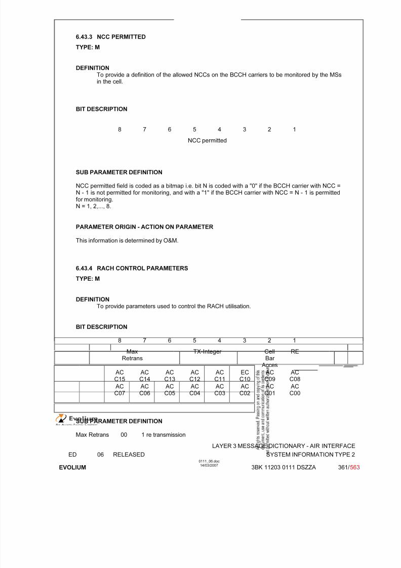
7/11/2019 1. Layer3 Air Interface Messages 0111_06
http://slidepdf.com/reader/full/1-layer3-air-interface-messages-011106 361/562
LAYER 3 MESSAGE DICTIONARY - AIR INTERFACE
ED 06 RELEASED SYSTEM INFORMATION TYPE 2
EVOLIUM
0111_06.doc14/03/2007
3BK 11203 0111 DSZZA 361/ 563
6.43.3 NCC PERMITTED
TYPE: M
DEFINITIONTo provide a definition of the allowed NCCs on the BCCH carriers to be monitored by the MSsin the cell.
BIT DESCRIPTION
8 7 6 5 4 3 2 1
NCC permitted
SUB PARAMETER DEFINITION
NCC permitted field is coded as a bitmap i.e. bit N is coded with a "0" if the BCCH carrier with NCC =N - 1 is not permitted for monitoring, and with a "1" if the BCCH carrier with NCC = N - 1 is permittedfor monitoring.N = 1, 2,..., 8.
PARAMETER ORIGIN - ACTION ON PARAMETER
This information is determined by O&M.
6.43.4 RACH CONTROL PARAMETERS
TYPE: M
DEFINITIONTo provide parameters used to control the RACH utilisation.
BIT DESCRIPTION
8 7 6 5 4 3 2 1
MaxRetrans
TX-Integer CellBar
Acces
RE
ACC15
ACC14
ACC13
ACC12
ACC11
ECC10
ACC09
ACC08
ACC07
ACC06
ACC05
ACC04
ACC03
ACC02
ACC01
ACC00
SUB PARAMETER DEFINITION
Max Retrans 00 1 re transmission

7/11/2019 1. Layer3 Air Interface Messages 0111_06
http://slidepdf.com/reader/full/1-layer3-air-interface-messages-011106 362/562
LAYER 3 MESSAGE DICTIONARY - AIR INTERFACE
ED 06 RELEASED SYSTEM INFORMATION TYPE 2
EVOLIUM
0111_06.doc14/03/2007
3BK 11203 0111 DSZZA 362/ 563
01 2 re transmissions10 4 re transmissions11 7 re transmissions
TX Integer Number of time slots to spread transmissionBits 6 5 4 3
0 0 0 0 3 slots used to spread transmission0 0 0 1 4 slots used to spread transmission0 0 1 0 5 slots used to spread transmission0 0 1 1 6 slots used to spread transmission0 1 0 0 7 slots used to spread transmission0 1 0 1 8 slots used to spread transmission0 1 1 0 9 slots used to spread transmission0 1 1 1 10 slots used to spread transmission1 0 0 0 11 slots used to spread transmission1 0 0 1 12 slots used to spread transmission1 0 1 0 14 slots used to spread transmission1 0 1 1 16 slots used to spread transmission1 1 0 0 20 slots used to spread transmission
1 1 0 1 25 slots used to spread transmission1 1 1 0 32 slots used to spread transmission1 1 1 1 50 slots used to spread transmission
Cell Bar Access: Cell barred for access0: the cell is not barred.1: the cell is barred.
RE Call Re-establishment allowed0: Re-establishment allowed in the cell1: Re-establishment not allowed in the cell
EC Emergency Call allowed (Octet 3 bit 3)0: Emergency Call allowed in the cell to all MSs1: Emergency Call not allowed in the cell except for the MSs that belong to one of the classes
between 11 to 15
AC CN : Access Control Class N (octet 3 except bit 3) and octet 4.
For a mobile station with AC CN, access is not barredif the AC CN bit is coded with "0" ; N = 0,1..9,11..15.
PARAMETER ORIGIN - ACTION ON PARAMETER
All the parameters are given to BSC during configuration and may be changed with OMC requests or by BSC due to "Overload" or "Reset" actions.

7/11/2019 1. Layer3 Air Interface Messages 0111_06
http://slidepdf.com/reader/full/1-layer3-air-interface-messages-011106 363/562
LAYER 3 MESSAGE DICTIONARY - AIR INTERFACE
ED 06 RELEASED SYSTEM INFORMATION TYPE 2bis
EVOLIUM
0111_06.doc14/03/2007
3BK 11203 0111 DSZZA 363/ 563
6.44 SYSTEM INFORMATION TYPE 2BIS
NAME SYSTEM INFORMATION TYPE 2BIS
INTERFACE RADIO ABIS A
CHANNEL/ USAGE
BCCH
3GPP-REF 44.018
FUNCTION This message is sent on the BCCH by the network to stations within the cellgiving information of control of the RACH and of the extension of the BCCHallocation in the neighbour cells.
DIRECTION From: BTS To: MS
INFORMATION ELEMENT NAME TYPE COMMENT LENGTH(byte)
INFORMATIONELEMENT
LISTL2 Pseudo LengthHeader Extended BCCH Frequency ListRACH Control parametersSI 2bis Rest Octets
M V M V M V M V M V
121631
IMPLEMENTATION MAXIMUM LENGTH 23
NORMAL SITUATION ABNORMAL SITUATION TIMER
FOLLOWINGEVENT
SPECIFDOC. REF.
BSS Init of Telecom part (ref. [19])Overload Control (ref. [16])
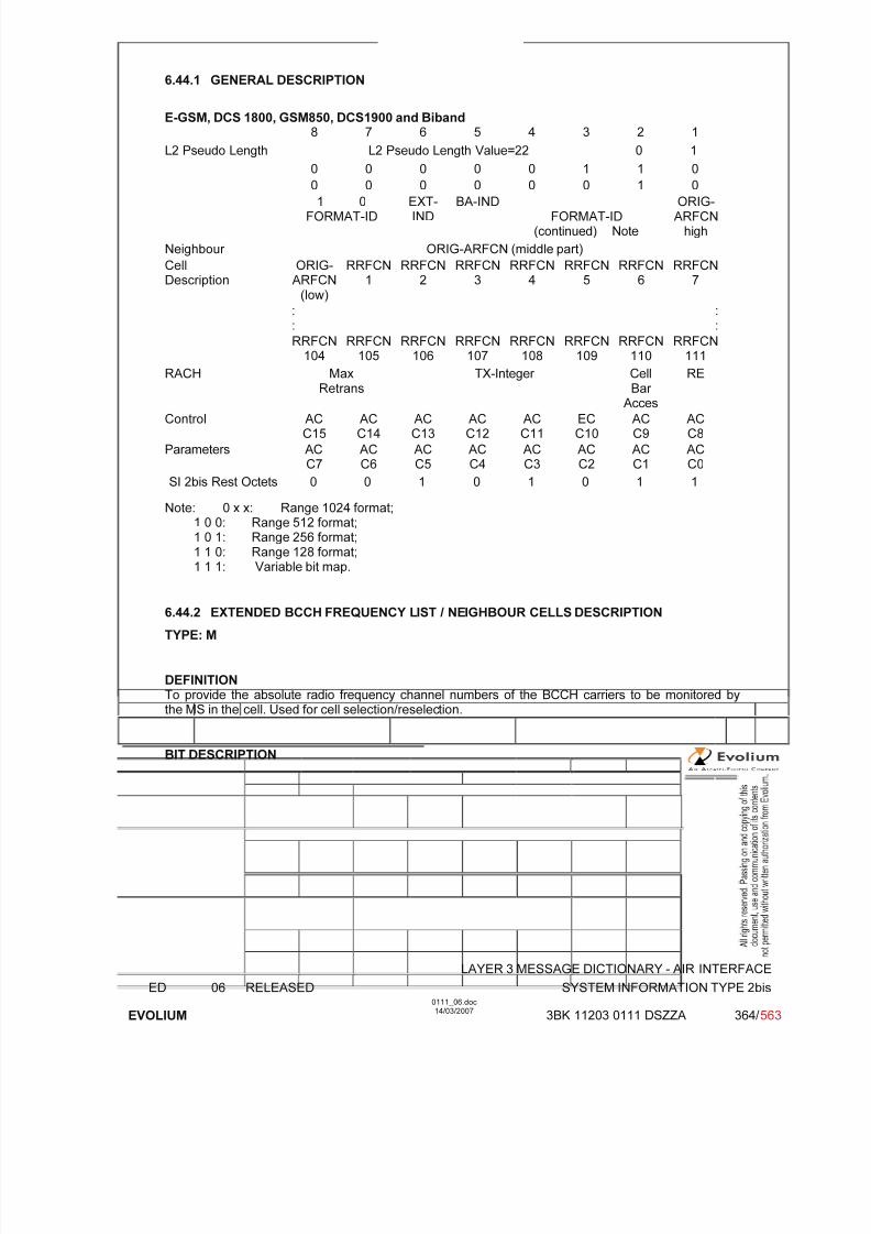
7/11/2019 1. Layer3 Air Interface Messages 0111_06
http://slidepdf.com/reader/full/1-layer3-air-interface-messages-011106 364/562
LAYER 3 MESSAGE DICTIONARY - AIR INTERFACE
ED 06 RELEASED SYSTEM INFORMATION TYPE 2bis
EVOLIUM
0111_06.doc14/03/2007
3BK 11203 0111 DSZZA 364/ 563
6.44.1 GENERAL DESCRIPTION
E-GSM, DCS 1800, GSM850, DCS1900 and Biband8 7 6 5 4 3 2 1
L2 Pseudo Length L2 Pseudo Length Value=22 0 1
0 0 0 0 0 1 1 0
0 0 0 0 0 0 1 01 0
FORMAT-IDEXT-IND
BA-INDFORMAT-ID
(continued) Note
ORIG-ARFCN
high
Neighbour ORIG-ARFCN (middle part)
CellDescription
ORIG-ARFCN
(low)
RRFCN1
RRFCN2
RRFCN3
RRFCN4
RRFCN5
RRFCN6
RRFCN7
::
::
RRFCN104
RRFCN105
RRFCN106
RRFCN107
RRFCN108
RRFCN109
RRFCN110
RRFCN111
RACH MaxRetrans TX-Integer CellBar Acces
RE
Control ACC15
ACC14
ACC13
ACC12
ACC11
ECC10
ACC9
ACC8
Parameters ACC7
ACC6
ACC5
ACC4
ACC3
ACC2
ACC1
ACC0
SI 2bis Rest Octets 0 0 1 0 1 0 1 1
Note: 0 x x: Range 1024 format;1 0 0: Range 512 format;1 0 1: Range 256 format;1 1 0: Range 128 format;
1 1 1: Variable bit map.
6.44.2 EXTENDED BCCH FREQUENCY LIST / NEIGHBOUR CELLS DESCRIPTION
TYPE: M
DEFINITIONTo provide the absolute radio frequency channel numbers of the BCCH carriers to be monitored bythe MS in the cell. Used for cell selection/reselection.
BIT DESCRIPTION

7/11/2019 1. Layer3 Air Interface Messages 0111_06
http://slidepdf.com/reader/full/1-layer3-air-interface-messages-011106 365/562
LAYER 3 MESSAGE DICTIONARY - AIR INTERFACE
ED 06 RELEASED SYSTEM INFORMATION TYPE 2bis
EVOLIUM
0111_06.doc14/03/2007
3BK 11203 0111 DSZZA 365/ 563
Range 1024 format supported
8 7 6 5 4 3 2 1
1 0FORMAT-ID
EXT-IND
BA-IND 0FORM-ID
F0 W(1) (high part) 1
W(1) (low part) 2
W(2) (high part) 3
W(2)(low)
W(3) (high part) 4
W(3) (low part) W(4) (high part) 5
W(4) (low part) W(5) (high part) 6
W(5) (low part) W(6) (high part) 7
W(6) (low part) W(7) (high part) 8
W(7) (low part) W(8) (high part) 9
W(8)
(low)
W(9) 10
W(10) W(11)(high)
11
W(11) (low part) W(12) (high part) 12
W(12) (low part) W(13) (high part) 13
W(13) (low part) W(14) (high part) 14
W(14) (low part) W(15) (high part) 15
W(15) (low part) W(16) 16
SUB PARAMETER DEFINITION
FORMAT-ID : Format identifier.
EXT-IND : Extension Indication0 IE carries the complete BA1 IE carries a part of the BA
BA-IND : BCCH allocation sequence number indicationRange 0 to 1.
F0 : Frequency indicator 0 ARFCN 0 is not a member of the set1 ARFCN 0 is a member of the set
W(i) : Each W(i) encodes a non negative integer in binary.if W(k) is null, W(K+1) to W(16) must be null also.

7/11/2019 1. Layer3 Air Interface Messages 0111_06
http://slidepdf.com/reader/full/1-layer3-air-interface-messages-011106 366/562
LAYER 3 MESSAGE DICTIONARY - AIR INTERFACE
ED 06 RELEASED SYSTEM INFORMATION TYPE 2bis
EVOLIUM
0111_06.doc14/03/2007
3BK 11203 0111 DSZZA 366/ 563
Range 512 format supported
8 7 6 5 4 3 2 1
1 0FORMAT-ID
EXT-IND
BA-IND 1 0 0FORMAT-ID (cont)
ORIG-ARFCN
1
ORIG-ARFCN (middle part) 2
ORIG-ARFCN
W(1) (high part) 3
W(1) (low part) W(2) (high part) 4
W(2) (low) W(3) (high part) 5
W(3) (low part) W(4) (high part) 6
W(4)(low)
W(5) 7
W(6) W(7)(high)
8
W(7) (low part) W(8) (high part) 9
W(8) (low part) W(9) (high part) 10
W(9) (low part) W(10) 11
W(11) W(12) (high) 12
W(12) (low part) W(13) (high part) 13
W(13) (low part) W(14) 14
W(15) W(16) (high) 15
W(16) (low part) W(17) 16
SUB PARAMETER DEFINITION
FORMAT-ID : Format identifier.
EXT-IND : Extension Indication0 IE carries the complete BA1 IE carries a part of the BA
BA-IND : BCCH allocation sequence number indicationRange 0 to 1.
ORIG-ARFCN : This field encodes the ARFCN of one frequency belonging to the set. This value isalso used as the origin of the bit map to generate all the other frequencies.
W(i) : Each W(i) encodes a non negative integer in binary.if W(k) is null, W(K+1) to W(17) must be null also.

7/11/2019 1. Layer3 Air Interface Messages 0111_06
http://slidepdf.com/reader/full/1-layer3-air-interface-messages-011106 367/562
LAYER 3 MESSAGE DICTIONARY - AIR INTERFACE
ED 06 RELEASED SYSTEM INFORMATION TYPE 2bis
EVOLIUM
0111_06.doc14/03/2007
3BK 11203 0111 DSZZA 367/ 563
Range 256 format supported
8 7 6 5 4 3 2 1
1 0FORMAT-ID
EXT-IND
BA-IND 1 0 1FORMAT-ID (cont)
ORIG-ARFCN
1
ORIG-ARFCN (middle part) 2
ORIG-ARFCN
W(1) (high part) 3
W(1)(loW)
W(2) 4
W(3) W(4)(high)
5
W(4) (low part) W(5) (high part) 6
W(5) (low part) W(6) (high part) 7
W(6)(low)
W(7) W(8)(high)
8
W(8) (low part) W(9) (high part) 9
W(9)(low)
W(10) W(11) (high) 10
W(11) (low part) W(12) 11
W(13) W(14) (high part) 12
W(14) (low part) W(15) W(16)(high)
13
W(16) (low part) W(17) W(18)(high)
14
W(18) (low part) W(19) W(20)(high)
15
W(20) (low part) W(21) 0
spare
16
SUB PARAMETER DEFINITION
FORMAT-ID : Format identifier.
EXT-IND : Extension Indication0 IE carries the complete BA1 IE carries a part of the BA
BA-IND : BCCH allocation sequence number indication
Range 0 to 1.
ORIG-ARFCN : This field encodes the ARFCN of one frequency belonging to the set. This value isalso used as the origin of the bit map to generate all the other frequencies.
W(i) : Each W(i) encodes a non negative integer in binary.if W(k) is null, W(K+1) to W(21) must be null also.

7/11/2019 1. Layer3 Air Interface Messages 0111_06
http://slidepdf.com/reader/full/1-layer3-air-interface-messages-011106 368/562
LAYER 3 MESSAGE DICTIONARY - AIR INTERFACE
ED 06 RELEASED SYSTEM INFORMATION TYPE 2bis
EVOLIUM
0111_06.doc14/03/2007
3BK 11203 0111 DSZZA 368/ 563
Range 128 format supported
8 7 6 5 4 3 2 1
1 0FORMAT-ID
EXT-IND
BA-IND 1 1 1FORMAT-ID (cont)
ORIG-ARFCN
1
ORIG-ARFCN (middle part) 2
ORIG-ARFCN
W(1) 3
W(2) W(3) (high part) 4
W(3) (low part) W(4) (high part) 5
W(4)(low)
W(5) W(6) (high part) 6
W(6) (low part) W(7) 7
W(8) W(9) 8
W(10) W(11) 9
W(12) W(13) 10
W(14) W(15) 11
W(16) W(17) W(18) (high) 12
W(18)(low)
W(19) W(20) W(21)(high)
13
W(21) (low) W(22) W(23) 14
W(24) W(25) W(26) (high) 15
W(26)(low)
W(27) W(28) 0spare
16
SUB PARAMETER DEFINITION
FORMAT-ID : Format identifier.
EXT-IND : Extension Indication0 IE carries the complete BA1 IE carries a part of the BA
BA-IND : BCCH allocation sequence number indicationRange 0 to 1.
ORIG-ARFCN : This field encodes the ARFCN of one frequency belonging to the set. This value isalso used as the origin of the bit map to generate all the other frequencies.
W(i) : Each W(i) encodes a non negative integer in binary.if W(k) is null, W(K+1) to W(28) must be null also.
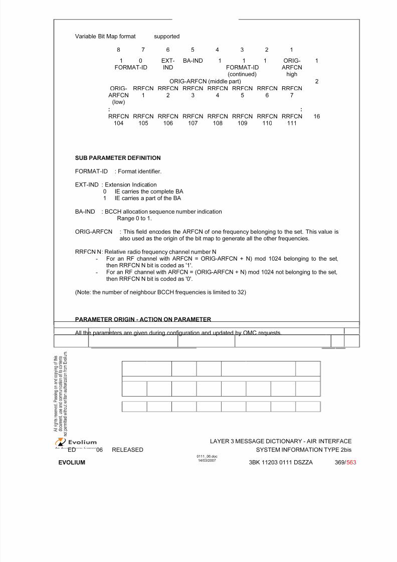
7/11/2019 1. Layer3 Air Interface Messages 0111_06
http://slidepdf.com/reader/full/1-layer3-air-interface-messages-011106 369/562
LAYER 3 MESSAGE DICTIONARY - AIR INTERFACE
ED 06 RELEASED SYSTEM INFORMATION TYPE 2bis
EVOLIUM
0111_06.doc14/03/2007
3BK 11203 0111 DSZZA 369/ 563
Variable Bit Map format supported
8 7 6 5 4 3 2 1
1 0FORMAT-ID
EXT-IND
BA-IND 1 1 1FORMAT-ID(continued)
ORIG-ARFCN
high
1
ORIG-ARFCN (middle part) 2
ORIG-ARFCN
(low)
RRFCN1
RRFCN2
RRFCN3
RRFCN4
RRFCN5
RRFCN6
RRFCN7
: :
RRFCN104
RRFCN105
RRFCN106
RRFCN107
RRFCN108
RRFCN109
RRFCN110
RRFCN111
16
SUB PARAMETER DEFINITION
FORMAT-ID : Format identifier.
EXT-IND : Extension Indication0 IE carries the complete BA1 IE carries a part of the BA
BA-IND : BCCH allocation sequence number indicationRange 0 to 1.
ORIG-ARFCN : This field encodes the ARFCN of one frequency belonging to the set. This value isalso used as the origin of the bit map to generate all the other frequencies.
RRFCN N : Relative radio frequency channel number N
- For an RF channel with ARFCN = ORIG-ARFCN + N) mod 1024 belonging to the set,then RRFCN N bit is coded as '1'.
- For an RF channel with ARFCN = (ORIG-ARFCN + N) mod 1024 not belonging to the set,then RRFCN N bit is coded as '0'.
(Note: the number of neighbour BCCH frequencies is limited to 32)
PARAMETER ORIGIN - ACTION ON PARAMETER
All the parameters are given during configuration and updated by OMC requests.

7/11/2019 1. Layer3 Air Interface Messages 0111_06
http://slidepdf.com/reader/full/1-layer3-air-interface-messages-011106 370/562
LAYER 3 MESSAGE DICTIONARY - AIR INTERFACE
ED 06 RELEASED SYSTEM INFORMATION TYPE 2bis
EVOLIUM
0111_06.doc14/03/2007
3BK 11203 0111 DSZZA 370/ 563
6.44.3 RACH CONTROL PARAMETERS
TYPE: M
DEFINITIONTo provide parameters used to control the RACH utilisation.
BIT DESCRIPTION
8 7 6 5 4 3 2 1
MaxRetrans
TX-Integer CellBar
Acces
RE
ACC15
ACC14
ACC13
ACC12
ACC11
ECC10
ACC09
ACC08
ACC07
ACC06
ACC05
ACC04
ACC03
ACC02
ACC01
ACC00
SUB PARAMETER DEFINITION
Max Retrans 00 1 re transmission01 2 re transmissions10 4 re transmissions11 7 re transmissions
TX Integer Number of time slots to spread transmissionBits 6 5 4 3
0 0 0 0 3 slots used to spread transmission
0 0 0 1 4 slots used to spread transmission0 0 1 0 5 slots used to spread transmission0 0 1 1 6 slots used to spread transmission0 1 0 0 7 slots used to spread transmission0 1 0 1 8 slots used to spread transmission0 1 1 0 9 slots used to spread transmission0 1 1 1 10 slots used to spread transmission1 0 0 0 11 slots used to spread transmission1 0 0 1 12 slots used to spread transmission1 0 1 0 14 slots used to spread transmission1 0 1 1 16 slots used to spread transmission1 1 0 0 20 slots used to spread transmission1 1 0 1 25 slots used to spread transmission1 1 1 0 32 slots used to spread transmission1 1 1 1 50 slots used to spread transmission
Cell Bar Access: Cell barred for access0: the cell is not barred.1: the cell is barred.
RE Call Re-establishment allowed0: Re-establishment allowed in the cell1: Re-establishment not allowed in the cell
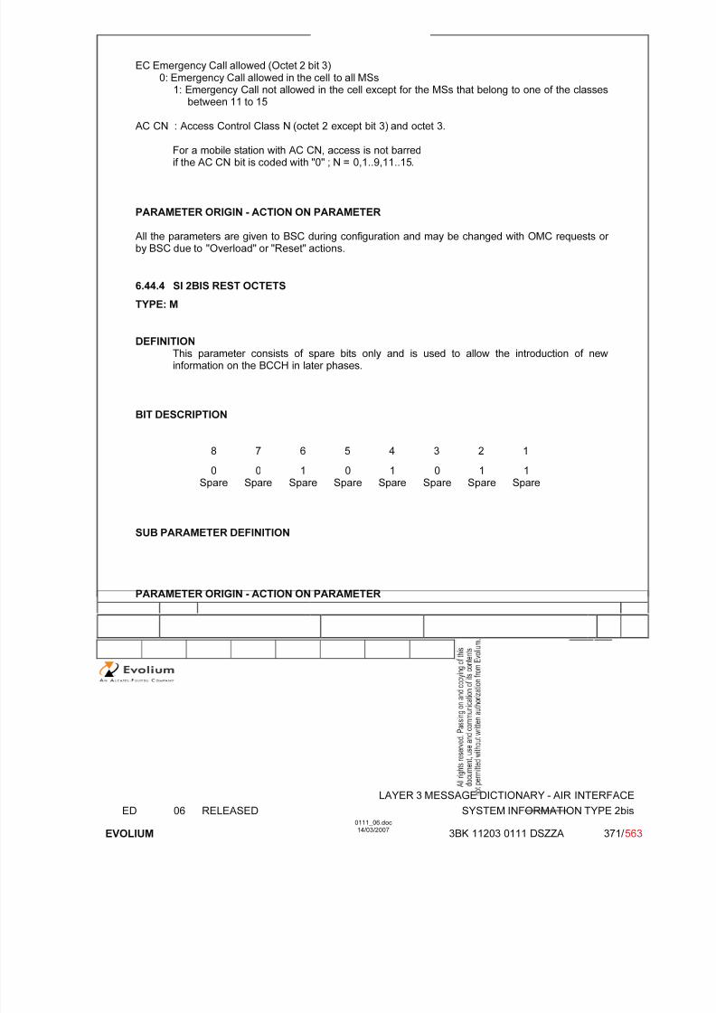
7/11/2019 1. Layer3 Air Interface Messages 0111_06
http://slidepdf.com/reader/full/1-layer3-air-interface-messages-011106 371/562
LAYER 3 MESSAGE DICTIONARY - AIR INTERFACE
ED 06 RELEASED SYSTEM INFORMATION TYPE 2bis
EVOLIUM
0111_06.doc14/03/2007
3BK 11203 0111 DSZZA 371/ 563
EC Emergency Call allowed (Octet 2 bit 3)0: Emergency Call allowed in the cell to all MSs
1: Emergency Call not allowed in the cell except for the MSs that belong to one of the classesbetween 11 to 15
AC CN : Access Control Class N (octet 2 except bit 3) and octet 3.
For a mobile station with AC CN, access is not barredif the AC CN bit is coded with "0" ; N = 0,1..9,11..15.
PARAMETER ORIGIN - ACTION ON PARAMETER
All the parameters are given to BSC during configuration and may be changed with OMC requests or by BSC due to "Overload" or "Reset" actions.
6.44.4 SI 2BIS REST OCTETS
TYPE: M
DEFINITIONThis parameter consists of spare bits only and is used to allow the introduction of newinformation on the BCCH in later phases.
BIT DESCRIPTION
8 7 6 5 4 3 2 1
0Spare
0Spare
1Spare
0Spare
1Spare
0Spare
1Spare
1Spare
SUB PARAMETER DEFINITION
PARAMETER ORIGIN - ACTION ON PARAMETER

7/11/2019 1. Layer3 Air Interface Messages 0111_06
http://slidepdf.com/reader/full/1-layer3-air-interface-messages-011106 372/562
LAYER 3 MESSAGE DICTIONARY - AIR INTERFACE
ED 06 RELEASED SYSTEM INFORMATION TYPE 2ter
EVOLIUM
0111_06.doc14/03/2007
3BK 11203 0111 DSZZA 372/ 563
6.45 SYSTEM INFORMATION TYPE 2TER
NAME SYSTEM INFORMATION TYPE 2TER
INTERFACE RADIO ABIS A
CHANNEL/ USAGE
BCCH
3GPP-REF 44.018
FUNCTION This message is sent optionally on the BCCH by the network to stations withinthe cell giving information on the extension of the BCCH allocation in theneighbour cells. The SI2ter message may also provide the MS with informationon the 2G-to-3G cell reselections.
DIRECTION From: BTS To: MS
INFORMATION ELEMENT NAME TYPE COMMENT LENGTH(byte)
INFORMATIONELEMENT
LISTL2 Pseudo Length
Header Extended BCCH Frequency ListSI 2ter Rest Octets
M V
M V M V M V
(1)1
2164
IMPLEMENTATION MAXIMUM LENGTH 23
NORMAL SITUATION ABNORMAL SITUATION TIMER
FOLLOWINGEVENT
SPECIFDOC. REF.
BSS Init of Telecom part (ref. [19])Overload Control (ref. [16])
(1) The ALCATEL BSS is compliant to GSM ETR 09.94 for phase 1 MS in biband networks. L2pseudo-length of SYSTEM INFORMATION TYPE 2ter is set to 0.
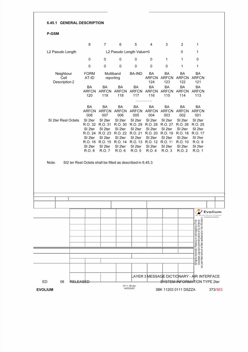
7/11/2019 1. Layer3 Air Interface Messages 0111_06
http://slidepdf.com/reader/full/1-layer3-air-interface-messages-011106 373/562
LAYER 3 MESSAGE DICTIONARY - AIR INTERFACE
ED 06 RELEASED SYSTEM INFORMATION TYPE 2ter
EVOLIUM
0111_06.doc14/03/2007
3BK 11203 0111 DSZZA 373/ 563
6.45.1 GENERAL DESCRIPTION
P-GSM
8 7 6 5 4 3 2 1
L2 Pseudo Length L2 Pseudo Length Value=0 0 1
0 0 0 0 0 1 1 0
0 0 0 0 0 0 1 1
FORMAT-ID
Multibandreporting
BA-IND BAARFCN
124
BAARFCN
123
BAARFCN
122
BAARFCN
121
BAARFCN
120
BAARFCN
119
BAARFCN
118
BAARFCN
117
BAARFCN
116
BAARFCN
115
BAARFCN
114
BAARFCN
113
Neighbour Cell
Description 2
................
BAARFCN008
BAARFCN007
BAARFCN006
BAARFCN005
BAARFCN004
BAARFCN003
BAARFCN002
BAARFCN001
SI 2ter Rest Octets SI 2ter R.O. 32
SI 2ter R.O. 31
SI 2ter R.O. 30
SI 2ter R.O. 29
SI 2ter R.O. 28
SI 2ter R.O. 27
SI 2ter R.O. 26
SI 2ter R.O. 25
SI 2ter R.O. 24
SI 2ter R.O. 23
SI 2ter R.O. 22
SI 2ter R.O. 21
SI 2ter R.O. 20
SI 2ter R.O. 19
SI 2ter R.O. 18
SI 2ter R.O. 17
SI 2ter R.O. 16
SI 2ter R.O. 15
SI 2ter R.O. 14
SI 2ter R.O. 13
SI 2ter R.O. 12
SI 2ter R.O. 11
SI 2ter R.O. 10
SI 2ter R.O. 9
SI 2ter R.O. 8
SI 2ter R.O. 7
SI 2ter R.O. 6
SI 2ter R.O. 5
SI 2ter R.O. 4
SI 2ter R.O. 3
SI 2ter R.O. 2
SI 2ter R.O. 1
Note: SI2 ter Rest Octets shall be filled as described in 6.45.3.
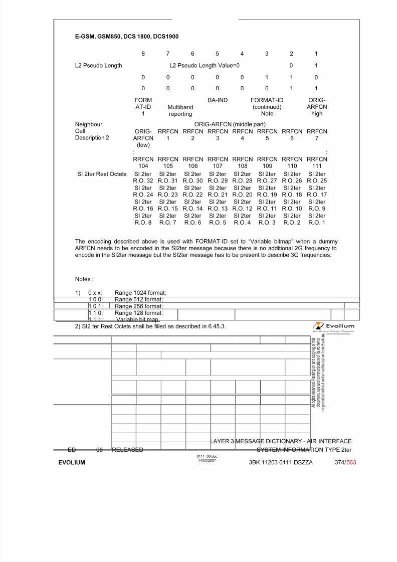
7/11/2019 1. Layer3 Air Interface Messages 0111_06
http://slidepdf.com/reader/full/1-layer3-air-interface-messages-011106 374/562
LAYER 3 MESSAGE DICTIONARY - AIR INTERFACE
ED 06 RELEASED SYSTEM INFORMATION TYPE 2ter
EVOLIUM
0111_06.doc14/03/2007
3BK 11203 0111 DSZZA 374/ 563
E-GSM, GSM850, DCS 1800, DCS1900
8 7 6 5 4 3 2 1
L2 Pseudo Length L2 Pseudo Length Value=0 0 1
0 0 0 0 0 1 1 0
0 0 0 0 0 0 1 1
FORMAT-ID
1Multibandreporting
BA-IND FORMAT-ID(continued)
Note
ORIG-ARFCN
high
ORIG-ARFCN (middle part)Neighbour CellDescription 2
ORIG-ARFCN
(low)
RRFCN1
RRFCN2
RRFCN3
RRFCN4
RRFCN5
RRFCN6
RRFCN7
: :
RRFCN104
RRFCN105
RRFCN106
RRFCN107
RRFCN108
RRFCN109
RRFCN110
RRFCN111
SI 2ter Rest Octets SI 2ter R.O. 32
SI 2ter R.O. 31
SI 2ter R.O. 30
SI 2ter R.O. 29
SI 2ter R.O. 28
SI 2ter R.O. 27
SI 2ter R.O. 26
SI 2ter R.O. 25
SI 2ter R.O. 24
SI 2ter R.O. 23
SI 2ter R.O. 22
SI 2ter R.O. 21
SI 2ter R.O. 20
SI 2ter R.O. 19
SI 2ter R.O. 18
SI 2ter R.O. 17
SI 2ter R.O. 16
SI 2ter R.O. 15
SI 2ter R.O. 14
SI 2ter R.O. 13
SI 2ter R.O. 12
SI 2ter R.O. 11
SI 2ter R.O. 10
SI 2ter R.O. 9
SI 2ter R.O. 8
SI 2ter R.O. 7
SI 2ter R.O. 6
SI 2ter R.O. 5
SI 2ter R.O. 4
SI 2ter R.O. 3
SI 2ter R.O. 2
SI 2ter R.O. 1
The encoding described above is used with FORMAT-ID set to “Variable bitmap” when a dummyARFCN needs to be encoded in the SI2ter message because there is no additional 2G frequency toencode in the SI2ter message but the SI2ter message has to be present to describe 3G frequencies.
Notes :
1) 0 x x: Range 1024 format;1 0 0: Range 512 format;1 0 1: Range 256 format;1 1 0: Range 128 format;1 1 1: Variable bit map.
2) SI2 ter Rest Octets shall be filled as described in 6.45.3.

7/11/2019 1. Layer3 Air Interface Messages 0111_06
http://slidepdf.com/reader/full/1-layer3-air-interface-messages-011106 375/562
LAYER 3 MESSAGE DICTIONARY - AIR INTERFACE
ED 06 RELEASED SYSTEM INFORMATION TYPE 2ter
EVOLIUM
0111_06.doc14/03/2007
3BK 11203 0111 DSZZA 375/ 563
6.45.2 EXTENDED BCCH FREQUENCY LIST / NEIGHBOUR CELLS DESCRIPTION 2
TYPE: M
DEFINITION
To provide the absolute radio frequency channel numbers of the BCCH carriers to be monitored by
the MS in the cell. Used for cell selection/reselection.
BIT DESCRIPTION
Bitmap 0 Format supported
8 7 6 5 4 3 2 1
0FORMAT-ID
MultibandReporting
BA-IND BAARFCN
124
BAARFCN
123
BAARFCN
122
BAARFCN
121
1
BA
ARFCN120
BA
ARFCN119
BA
ARFCN118
BA
ARFCN117
BA
ARFCN116
BA
ARFCN115
BA
ARFCN114
BA
ARFCN113
2
................
BAARFCN
008
BAARFCN
007
BAARFCN
006
BAARFCN
005
BAARFCN
004
BAARFCN
003
BAARFCN
002
BAARFCN
001
16
SUB PARAMETER DEFINITION
FORMAT-ID Format identifier Multiband reporting Binary coded minimum number of cells of each supported band to be included
in MEASUREMENT REPORT message (if available). Range 0 to 3, set byO&M.
BA-IND BCCH allocation sequence number indicationRange 0 to 1
BA ARFCN N BCCH Allocation Absolute RF Channel Number Nif ARFCN = N belongs to the BCCH allocation, BA ARFCN N bit is coded with"1" N = 1,2 ... 124if not, BA ARFCN N bit is coded with "0" ; N=1,2 ...124
(Note : the number of neighbour BCCH frequencies is limited to 32)

7/11/2019 1. Layer3 Air Interface Messages 0111_06
http://slidepdf.com/reader/full/1-layer3-air-interface-messages-011106 376/562
LAYER 3 MESSAGE DICTIONARY - AIR INTERFACE
ED 06 RELEASED SYSTEM INFORMATION TYPE 2ter
EVOLIUM
0111_06.doc14/03/2007
3BK 11203 0111 DSZZA 376/ 563
Range 1024 format supported
8 7 6 5 4 3 2 1
1FORMAT-ID
MultibandReporting
BA-IND 0
FORMAT-ID
F0 W(1) (high part) 1
W(1) (low part) 2
W(2) (high part) 3
W(2)(low)
W(3) (high part) 4
W(3) (low part) W(4) (high part) 5
W(4) (low part) W(5) (high part) 6
W(5) (low part) W(6) (high part) 7
W(6) (low part) W(7) (high part) 8
W(7) (low part) W(8) (high part) 9
W(8)(low)
W(9) 10
W(10) W(11)(high)
11
W(11) (low part) W(12) (high part) 12
W(12) (low part) W(13) (high part) 13
W(13) (low part) W(14) (high part) 14
W(14) (low part) W(15) (high part) 15
W(15) (low part) W(16) 16
SUB PARAMETER DEFINITION
FORMAT-ID Format identifier Multiband reporting Binary coded minimum number of cells of each supported band to be
included in MEASUREMENT REPORT message (if available). Range 0 to 3,set by O&M
BA-IND BCCH allocation sequence number indicationRange 0 to 1
F0 Frequency indicator 0 ARFCN 0 is not a member of the set1 ARFCN 0 is a member of the set
W(i) Each W(i) encodes a non negative integer in binaryif W(k) is null, W(K+1) to W(16) must be null also

7/11/2019 1. Layer3 Air Interface Messages 0111_06
http://slidepdf.com/reader/full/1-layer3-air-interface-messages-011106 377/562
LAYER 3 MESSAGE DICTIONARY - AIR INTERFACE
ED 06 RELEASED SYSTEM INFORMATION TYPE 2ter
EVOLIUM
0111_06.doc14/03/2007
3BK 11203 0111 DSZZA 377/ 563
Range 512 format supported
8 7 6 5 4 3 2 1
1FORMAT-ID
MultibandReporting
BA-IND 1 0 0FORMAT-ID(continued)
ORIG-ARFCN
1
ORIG-ARFCN (middle part) 2
ORIG-ARFCN
W(1) (high part) 3
W(1) (low part) W(2) (high part) 4
W(2) (low) W(3) (high part) 5
W(3) (low part) W(4) (high part) 6
W(4)(low)
W(5) 7
W(6) W(7)(high)
8
W(7) (low part) W(8) (high part) 9
W(8) (low part) W(9) (high part) 10
W(9) (low part) W(10) 11
W(11) W(12) (high) 12
W(12) (low part) W(13) (high part) 13
W(13) (low part) W(14) 14
W(15) W(16) (high) 15
W(16) (low part) W(17) 16
SUB PARAMETER DEFINITION
FORMAT-ID Format identifier Multiband reporting Binary coded minimum number of cells of each supported band to be
included in MEASUREMENT REPORT message (if available). Range 0 to 3,set by O&M
BA-IND BCCH allocation sequence number indicationRange 0 to 1
ORIG-ARFCN This field encodes the ARFCN of one frequency belonging to the set. Thisvalue is also used as the origin of the bit map to generate all the other frequencies.
W(i) Each W(i) encodes a non negative integer in binary.if W(k) is null, W(K+1) to W(17) must be null also.
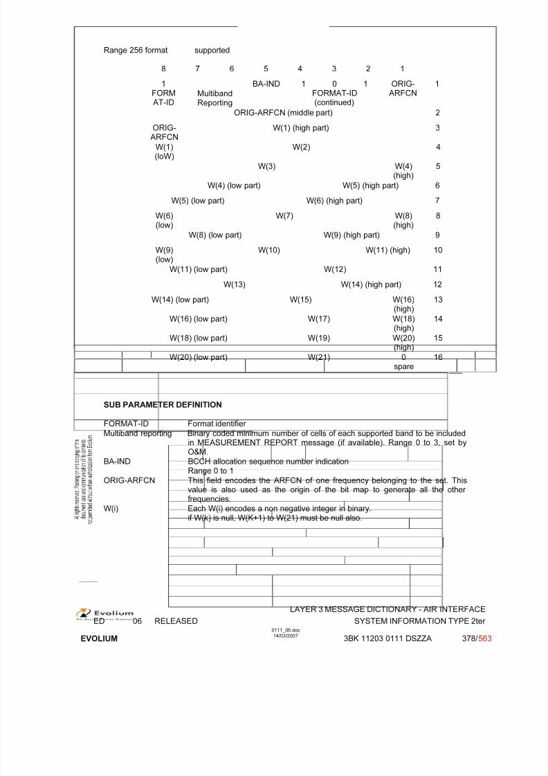
7/11/2019 1. Layer3 Air Interface Messages 0111_06
http://slidepdf.com/reader/full/1-layer3-air-interface-messages-011106 378/562
LAYER 3 MESSAGE DICTIONARY - AIR INTERFACE
ED 06 RELEASED SYSTEM INFORMATION TYPE 2ter
EVOLIUM
0111_06.doc14/03/2007
3BK 11203 0111 DSZZA 378/ 563
Range 256 format supported
8 7 6 5 4 3 2 1
1FORMAT-ID
MultibandReporting
BA-IND 1 0 1FORMAT-ID(continued)
ORIG-ARFCN
1
ORIG-ARFCN (middle part) 2
ORIG-ARFCN
W(1) (high part) 3
W(1)(loW)
W(2) 4
W(3) W(4)(high)
5
W(4) (low part) W(5) (high part) 6
W(5) (low part) W(6) (high part) 7
W(6)(low)
W(7) W(8)(high)
8
W(8) (low part) W(9) (high part) 9W(9)(low)
W(10) W(11) (high) 10
W(11) (low part) W(12) 11
W(13) W(14) (high part) 12
W(14) (low part) W(15) W(16)(high)
13
W(16) (low part) W(17) W(18)(high)
14
W(18) (low part) W(19) W(20)(high)
15
W(20) (low part) W(21) 0spare
16
SUB PARAMETER DEFINITION
FORMAT-ID Format identifier
Multiband reporting Binary coded minimum number of cells of each supported band to be includedin MEASUREMENT REPORT message (if available). Range 0 to 3, set byO&M.
BA-IND BCCH allocation sequence number indicationRange 0 to 1
ORIG-ARFCN This field encodes the ARFCN of one frequency belonging to the set. Thisvalue is also used as the origin of the bit map to generate all the other frequencies.
W(i) Each W(i) encodes a non negative integer in binary.if W(k) is null, W(K+1) to W(21) must be null also.

7/11/2019 1. Layer3 Air Interface Messages 0111_06
http://slidepdf.com/reader/full/1-layer3-air-interface-messages-011106 379/562
LAYER 3 MESSAGE DICTIONARY - AIR INTERFACE
ED 06 RELEASED SYSTEM INFORMATION TYPE 2ter
EVOLIUM
0111_06.doc14/03/2007
3BK 11203 0111 DSZZA 379/ 563
Range 128 format supported
8 7 6 5 4 3 2 1
1FORMAT-ID
MultibandReporting
BA-IND 1 1 0FORMAT-ID(continued)
ORIG-ARFCN
1
ORIG-ARFCN (middle part) 2
ORIG-ARFCN
W(1) 3
W(2) W(3) (high part) 4
W(3) (low part) W(4) (high part) 5
W(4)(low)
W(5) W(6) (high part) 6
W(6) (low part) W(7) 7
W(8) W(9) 8
W(10) W(11) 9
W(12) W(13) 10
W(14) W(15) 11
W(16) W(17) W(18) (high) 12
W(18)(low)
W(19) W(20) W(21)(high)
13
W(21) (low) W(22) W(23) 14
W(24) W(25) W(26) (high) 15
W(26)(low)
W(27) W(28) 0spare
16
SUB PARAMETER DEFINITION
FORMAT-ID Format identifier Multiband reporting Binary coded minimum number of cells of each supported band to be
included in MEASUREMENT REPORT message (if available). Range 0 to 3,set by O&M.
BA-IND BCCH allocation sequence number indicationRange 0 to 1.
ORIG-ARFCN This field encodes the ARFCN of one frequency belonging to the set. Thisvalue is also used as the origin of the bit map to generate all the other frequencies.
W(i) Each W(i) encodes a non negative integer in binary.if W(k) is null, W(K+1) to W(28) must be null also.

7/11/2019 1. Layer3 Air Interface Messages 0111_06
http://slidepdf.com/reader/full/1-layer3-air-interface-messages-011106 380/562
LAYER 3 MESSAGE DICTIONARY - AIR INTERFACE
ED 06 RELEASED SYSTEM INFORMATION TYPE 2ter
EVOLIUM
0111_06.doc14/03/2007
3BK 11203 0111 DSZZA 380/ 563
Variable Bit Map format supported
8 7 6 5 4 3 2 1
1FORM
AT-ID
Multiband
Reporting
BA-IND 1 1 1FORMAT-ID
(continued)
ORIG-ARFCN
high
1
ORIG-ARFCN (middle part) 2
ORIG-ARFCN
(low)
RRFCN1
RRFCN2
RRFCN3
RRFCN4
RRFCN5
RRFCN6
RRFCN7
: :
RRFCN104
RRFCN105
RRFCN106
RRFCN107
RRFCN108
RRFCN109
RRFCN110
RRFCN111
16
SUB PARAMETER DEFINITION
FORMAT-ID Format identifier Multiband reporting Binary coded minimum number of cells of each supported band to be
included in MEASUREMENT REPORT message (if available). Range 0 to 3,set by O&M.
BA-IND BCCH allocation sequence number indicationRange 0 to 1
ORIG-ARFCN This field encodes the ARFCN of one frequency belonging to the set. Thisvalue is also used as the origin of the bit map to generate all the other frequencies.
RRFCN N Relative radio frequency channel number NFor an RF channel with ARFCN = ORIG-ARFCN + N) mod 1024 belongingto the set, then RRFCN N bit is coded as '1'.For an RF channel with ARFCN = (ORIG-ARFCN + N) mod 1024 notbelonging to the set, then RRFCN N bit is coded as '0'.Note: the number of neighbour BCCH frequencies is limited to 32
The following setting of the variable format is used when a dummy ARFCN needs to be encoded inthe SI2ter message:
FORMAT-ID Set to “Variable bitmap”Multiband reporting Set to “00”BA-IND BCCH allocation sequence number indication
Range 0 to 1.
ORIG-ARFCN This field encodes the dummy ARFCN defined by the parameter DUMMY_ARFCN_FOR_SI2TER. This value is also used as the origin of the bitmap to generate all the other frequencies.
RRFCN N Relative radio frequency channel number NAll the RRFCN are set to “0”.
PARAMETER ORIGIN - ACTION ON PARAMETER
All the parameters are given during configuration and updated by OMC requests.
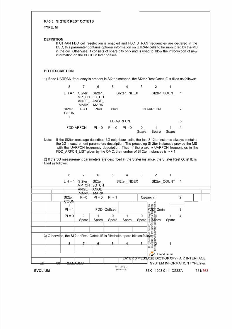
7/11/2019 1. Layer3 Air Interface Messages 0111_06
http://slidepdf.com/reader/full/1-layer3-air-interface-messages-011106 381/562
LAYER 3 MESSAGE DICTIONARY - AIR INTERFACE
ED 06 RELEASED SYSTEM INFORMATION TYPE 2ter
EVOLIUM
0111_06.doc14/03/2007
3BK 11203 0111 DSZZA 381/ 563
6.45.3 SI 2TER REST OCTETS
TYPE: M
DEFINITIONIf UTRAN FDD cell reselection is enabled and FDD UTRAN frequencies are declared in theBSC, this parameter contains optional information on UTRAN cells to be monitored by the MS
in the cell. Otherwise, it consists of spare bits only and is used to allow the introduction of newinformation on the BCCH in later phases.
BIT DESCRIPTION
1) If one UARFCN frequency is present in SI2ter instance, the SI2ter Rest Octet IE is filled as follows:
8 7 6 5 4 3 2 1
L|H = 1 SI2ter_ MP_CH
ANGE_ MARK
SI2ter_ 3G_CH
ANGE_ MARK
SI2ter_INDEX SI2ter_COUNT 1
SI2ter_ COUN
T
PI=1 PI=0 PI=1 FDD-ARFCN 2
FDD-ARFCN 3
FDD-ARFCN PI = 0 PI = 0 PI = 0 0Spare
1Spare
1Spare
4
Note: If the SI2ter message describes 3G neighbour cells, the last SI 2ter instance always containsthe 3G measurement parameters description. The preceding SI 2ter instances provide the MS with the UARFCN frequency description. Thus, if there are n UARFCN frequencies in the
FDD_ARFCN_LIST given by the OMC, the number of SI 2ter instances is n + 1.
2) If the 3G measurement parameters are described in the SI2ter instance, the SI 2ter Rest Octet IE isfilled as follows:
8 7 6 5 4 3 2 1
L|H = 1 SI2ter_ MP_CHANGE_ MARK
SI2ter_ 3G_CHANGE_ MARK
SI2ter_INDEX SI2ter_COUNT 1
SI2ter_
COUNT
PI=0 PI = 0 PI = 1 Qsearch_I 2
PI = 1 FDD_Qoffset FDD_Qmin 3
PI = 0 0Spare
1Spare
0Spare
1Spare
0Spare
1Spare
1Spare
4
3) Otherwise, the SI 2ter Rest Octets IE is filled with spare bits as follows:
8 7 6 5 4 3 2 1
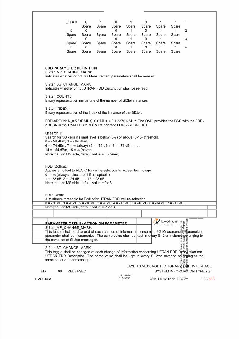
7/11/2019 1. Layer3 Air Interface Messages 0111_06
http://slidepdf.com/reader/full/1-layer3-air-interface-messages-011106 382/562
LAYER 3 MESSAGE DICTIONARY - AIR INTERFACE
ED 06 RELEASED SYSTEM INFORMATION TYPE 2ter
EVOLIUM
0111_06.doc14/03/2007
3BK 11203 0111 DSZZA 382/ 563
L|H = 0 0Spare
1Spare
0Spare
1Spare
0Spare
1Spare
1Spare
1
0Spare
0Spare
1Spare
0Spare
1Spare
0Spare
1Spare
1Spare
2
0Spare
0Spare
1Spare
0Spare
1Spare
0Spare
1Spare
1Spare
3
0
Spare
0
Spare
1
Spare
0
Spare
1
Spare
0
Spare
1
Spare
1
Spare
4
SUB PARAMETER DEFINITIONSI2ter_MP_CHANGE_MARK:Indicates whether or not 3G Measurement parameters shall be re-read.
SI2ter_3G_CHANGE_MARK:Indicates whether or not UTRAN FDD Description shall be re-read.
SI2ter_COUNT :Binary representation minus one of the number of SI2ter instances.
SI2ter_INDEX :Binary representation of the index of the instance of the SI2ter.
FDD-ARFCN: Nu = 5 * (F MHz), 0.0 MHz ≤ F ≤ 3276.6 MHz. The OMC provides the BSC with the FDD-ARFCN in the O&M FDD ARFCN list denoted FDD_ARFCN_LIST.
Qsearch_I:Search for 3G cells if signal level is below (0-7) or above (8-15) threshold.0 = - 98 dBm, 1 = - 94 dBm, … ,
6 = - 74 dBm, 7 = ∞ (always) 8 = - 78 dBm, 9 = - 74 dBm, … ,
14 = - 54 dBm, 15 = ∞ (never).
Note that, on MS side, default value = ∞ (never).
FDD_Qoffset:Applies an offset to RLA_C for cell re-selection to access technology.
0 = - ∞ (always select a cell if acceptable),1 = -28 dB, 2 = -24 dB, … , 15 = 28 dB.Note that, on MS side, default value = 0 dB.
FDD_Qmin:A minimum threshold for Ec/No for UTRAN FDD cell re-selection.0 = -20 dB, 1 = -6 dB, 2 = -18 dB, 3 = -8 dB, 4 = -16 dB, 5 = -10 dB, 6 = -14 dB, 7 = -12 dB.
Note that, on MS side, default value = -12 dB.
PARAMETER ORIGIN - ACTION ON PARAMETERSI2ter_MP_CHANGE_MARK:This toggle shall be changed at each change of information concerning 3G Measurement Parametersparameter shall be incremented. The same value shall be kept in every SI 2ter instance belonging tothe same set of SI 2ter messages.
SI2ter_3G_CHANGE_MARK:This toggle shall be changed at each change of information concerning UTRAN FDD Description andUTRAN TDD Description. The same value shall be kept in every SI 2ter instance belonging to the
same set of SI 2ter messages.
7/11/2019 1. Layer3 Air Interface Messages 0111_06
http://slidepdf.com/reader/full/1-layer3-air-interface-messages-011106 383/562
LAYER 3 MESSAGE DICTIONARY - AIR INTERFACE
ED 06 RELEASED SYSTEM INFORMATION TYPE 2ter
EVOLIUM
0111_06.doc14/03/2007
3BK 11203 0111 DSZZA 383/ 563
SI2ter_INDEX:The SI2ter_INDEX field is binary coded, range 0 to 7, and indexes each instance of SI2ter.
All other sub-parameters are set by O & M and stored in BSC and may change according to OMCaction.

7/11/2019 1. Layer3 Air Interface Messages 0111_06
http://slidepdf.com/reader/full/1-layer3-air-interface-messages-011106 384/562
LAYER 3 MESSAGE DICTIONARY - AIR INTERFACE
ED 06 RELEASED SYSTEM INFORMATION TYPE 2quater
EVOLIUM
0111_06.doc14/03/2007
3BK 11203 0111 DSZZA 384/ 563
6.46 SYSTEM INFORMATION TYPE 2QUATER
NAME SYSTEM INFORMATION TYPE 2QUATER
INTERFACE RADIO ABIS A
CHANNEL/ USAGE
BCCH/ BCCH extended
3GPP-REF 44.018
FUNCTION This message is sent optionally on either the BCCH or the BCCH extended( if it isconfigured in the cell) by the network to stations within the cell giving informationon additional measurement and reporting parameters and/or UTRAN neighbour cells.
DIRECTION From: BTS To: MS
INFORMATION ELEMENT NAME TYPE COMMENT LENGTH(byte)
INFORMATIONELEMENT
LISTL2 Pseudo Length
Header SI 2quater Rest Octets
M V
M V M V
(1)1
220
IMPLEMENTATION MAXIMUM LENGTH 23
NORMAL SITUATION ABNORMAL SITUATION TIMER
FOLLOWINGEVENT
SPECIFDOC. REF.
BSS Init of Telecom part (ref. [19])Overload Control (ref. [16])
(1) The ALCATEL BSS is compliant to GSM ETR 09.94 for phase 1 MS in biband networks. L2pseudo-length of SYSTEM INFORMATION TYPE 2quater is set to 0.

7/11/2019 1. Layer3 Air Interface Messages 0111_06
http://slidepdf.com/reader/full/1-layer3-air-interface-messages-011106 385/562
LAYER 3 MESSAGE DICTIONARY - AIR INTERFACE
ED 06 RELEASED SYSTEM INFORMATION TYPE 2quater
EVOLIUM
0111_06.doc14/03/2007
3BK 11203 0111 DSZZA 385/ 563
6.46.1 GENERAL DESCRIPTION
8 7 6 5 4 3 2 1
L2 Pseudo Length L2 Pseudo Length Value=0 0 1
0 0 0 0 0 1 1 0
0 0 0 0 0 1 1 1
SI 2quater RestOctets
…....
SI2 quater Rest Octets shall be filled as described in 6.45.3.
……..
6.46.2 SI 2QUATER REST OCTETS
TYPE: M
DEFINITIONThe SI 2quater Rest Octets information element contains neighbour cell lists for UTRAN cells. For cellreselection, it is used to build the 3G Cell Reselection list.
BIT DESCRIPTION
Case of 3 UTRAN FDD ARFCNs (for a 2G cell , the number of ARFCNs is lower or equal to 3) andPBCCH not activated in the cell.
8 7 6 5 4 3 2 1
BA_ IND
3G_ BA_
IND
MP_CHANGE_
MARK
SI2quater_INDEX SI2quater_CO
UNT
1
SI2quater_COUNT PI=0 PI=0 PI=0 PI=0 PI=0 2
PI=0 PI=0 PI=1 PI=0 PI=0 PI=1 PI=0 PI=1 3
PI=0 FDD_ARFCN 4
FDD_ARFCN FDD_Indic0
5
NR_OF_FDD_CELLS PI=1 PI=0 FDD_ARFCN
6
FDD_ARFCN 7

7/11/2019 1. Layer3 Air Interface Messages 0111_06
http://slidepdf.com/reader/full/1-layer3-air-interface-messages-011106 386/562
LAYER 3 MESSAGE DICTIONARY - AIR INTERFACE
ED 06 RELEASED SYSTEM INFORMATION TYPE 2quater
EVOLIUM
0111_06.doc14/03/2007
3BK 11203 0111 DSZZA 386/ 563
FDD_ARFCN FDD_Indic0
NR_OF_FDD_CELLS
8
NR_OF_FDD_CELLS PI=1 PI=0 FDD_ARFCN 9
FDD_ARFCN 10
FDD_ARFCN FDD_Indic0
NR_OF_FDD_CELLS 11
NR_OF _FDD_ CELLS
PI=0 PI=0 PI=1 Qsearch_I 12
Qsearch_C_Ini
tial
PI=1 FDD_Qoffset FDD_REP_QU
ANT
FDD_MULTIRA T_REP
ORTING
13
FDD_MULTIRA T_REP
ORTING
FDD_Qmin PI=0 PI=1 Qsearch_P
14
Qsearch_P 3G_SEARCH_
PRIO
PI=0 PI=0 PI=0 PI=0 15
Case of 3 UTRAN FDD ARFCNs (for a 2G cell , the number of ARFCNs is lower or equal to 3) andPBCCH activated in the cell.
8 7 6 5 4 3 2 1
BA_ IND
3G_ BA_ IND
MP_CHANGE_ MARK
SI2quater_INDEX SI2quater_COUNT
1
SI2quater_COUNT PI=0 PI=0 PI=0 PI=0 PI=0 2
PI=0 PI=0 PI=1 PI=0 PI=0 PI=1 PI=0 PI=1 3
PI=0 FDD_ARFCN 4
FDD_ARFCN FDD_Indic0
5
NR_OF_FDD_CELLS PI=1 PI=0 FDD_ARFCN
6
FDD_ARFCN 7
FDD_ARFCN FDD_Indic0
NR_OF_FDD_CELLS
8
NR_OF_FDD_CELLS PI=1 PI=0 FDD_ARFCN 9
FDD_ARFCN 10
FDD_ARFCN FDD_Indic0
NR_OF_FDD_CELLS 11
NR_OF _FDD_ CELLS
PI=0 PI=0 PI=1 Qsearch_I 12
Qsearch_C_Ini
tial
PI=1 FDD_Qoffset FDD_REP_QU
ANT
FDD_MU
LTIRAT_ REPORTI
NG
13
FDD_MU
LTIRAT_ REPORTI
NG
FDD_Qmin PI=0 PI=0 Spare1
14

7/11/2019 1. Layer3 Air Interface Messages 0111_06
http://slidepdf.com/reader/full/1-layer3-air-interface-messages-011106 387/562
LAYER 3 MESSAGE DICTIONARY - AIR INTERFACE
ED 06 RELEASED SYSTEM INFORMATION TYPE 2quater
EVOLIUM
0111_06.doc14/03/2007
3BK 11203 0111 DSZZA 387/ 563
SUB PARAMETER DEFINITION
BA_IND:BCCH allocation sequence number indication.Range 0 to 1.
3G_BA_IND:3G BCCH allocation sequence number indication.
Indicates whether or not the MS shall re-read all instances and rebuild the 3G Neighbour Cell list.
MP_CHANGE_MARK:Indicates whether or not 3G Measurement parameters shall be re-read.0 at initialisation.
SI2quater_INDEX :This field is binary coded, range 0 to 15, and indexes each instance of SI2quater Rest Octet
information element.
SI2quater_COUNT :Binary representation minus one of the number of SI2quater instances.
FDD_ARFCN:UTRAN FDD central frequency.This IE set by O&M is defined as the UARFCN in 3GPP TS 25.101.
FDD_Indic0:This field indicates if the FDD_CELL_INFORMATION parameter value ‘0000000000’ is a member of the set or not.Set to 0
NR_OF_FDD_CELLSSet to 31
Qsearch_I:Search for 3G cells if signal level is below (0-7) or above (8-15) threshold.0 = - 98 dBm, 1 = - 94 dBm, … ,
6 = - 74 dBm, 7 = ∞ (always) 8 = - 78 dBm, 9 = - 74 dBm, … ,
14 = - 54 dBm, 15 = ∞ (never).
Note that, on MS side, default value = ∞ (never).Set by O&M
Qsearch_C_Initial
Indicates the Qsearch value to be used in connected mode before Qsearch_C is received,Set to 0 (use Q_Isearch)
FDD_Qoffset:Applies an offset to RLA_C for cell re-selection to access technology.
(0 = - ∞ (always select a cell if acceptable),1 = -28 dB, 2 = -24 dB, … , 15 = 28 dB.Note that, on MS side, default value = 0 dB.)???Set by O&M.
FDD_REP_QUANT:Indicates the reporting quantity for UTRAN FDD cells.Set to 0.
7/11/2019 1. Layer3 Air Interface Messages 0111_06
http://slidepdf.com/reader/full/1-layer3-air-interface-messages-011106 388/562
LAYER 3 MESSAGE DICTIONARY - AIR INTERFACE
ED 06 RELEASED SYSTEM INFORMATION TYPE 2quater
EVOLIUM
0111_06.doc14/03/2007
3BK 11203 0111 DSZZA 388/ 563
FDD_MULTIRAT_REPORTINGthe number of cells from the access technology/mode FDD (one or more) that shall be included in thelist of strongest cells or in the measurement report.Set to 0
FD_Qmin
A minimum threshold for Ec/No for UTRAN FDD cell re-selectionSet by O&M
Qsearch_PSearch for 3G cells if signal level below threshold (0-7) or above threshold (8-15)( for PBCCH).Set equal to Qsearch_I
3G_SEARCH_PRIOIndicate if 3G cells may be searched when BSIC decoding is requiredSet by O&M
PARAMETER ORIGIN - ACTION ON PARAMETER
BA_IND :The BA-IND is a one bit field which allows the BSC to differentiate MEASUREMENT REPORTsrelated to BCCH BA or to SACCH BA. To achieve this, the BSC shall ensure that BA-IND_SACCHis always the opposite of BA-IND_BCCH.
3G_BA_IND :It shall be toggled each time each time 3G Neighbour Cell information is changed.When the 3G_BA_IND parameter is changed, the MS shall re-read all instances and rebuild the3G Neighbour Cell list.
MP_CHANGE_MARK :
This parameter shall be toggled, each time 3G Measurement have been changed.

7/11/2019 1. Layer3 Air Interface Messages 0111_06
http://slidepdf.com/reader/full/1-layer3-air-interface-messages-011106 389/562
LAYER 3 MESSAGE DICTIONARY - AIR INTERFACE
ED 06 RELEASED SYSTEM INFORMATION TYPE 3
EVOLIUM
0111_06.doc14/03/2007
3BK 11203 0111 DSZZA 389/ 563
6.47 SYSTEM INFORMATION TYPE 3
NAME SYSTEM INFORMATION TYPE 3
INTERFACE RADIO ABIS A
CHANNEL/ USAGE
BCCH
3GPP-REF 44.018
FUNCTION This message is sent on the BCCH by the network to cell giving information of control of the RACH, of location area identification, of cell identity and variousother information about the cell.
DIRECTION From: BTS To: MS
INFORMATION ELEMENT NAME TYPE COMMENT LENGTH(byte)
INFORMATIONELEMENT
LISTL2 Pseudo LengthHeader Cell IdentityLocation Area ID.Control Channel DescriptionCell Options ( BCCH )Cell Selection ParametersRACH Control ParametersSI 3 Rest Octets
M V M V M V M V M V M V M V M V M V
122531234
IMPLEMENTATION MAXIMUM LENGTH 23
NORMAL SITUATION ABNORMAL SITUATION TIMER
FOLLOWINGEVENT
SPECIFDOC. REF.
Paging Access Control (ref. [1])Overload Control (ref. [16])BSS Initialisation of the Telecom part (ref. [19])
BSS Global Reset (ref. [21])System Information Management (ref. [24])

7/11/2019 1. Layer3 Air Interface Messages 0111_06
http://slidepdf.com/reader/full/1-layer3-air-interface-messages-011106 390/562
LAYER 3 MESSAGE DICTIONARY - AIR INTERFACE
ED 06 RELEASED SYSTEM INFORMATION TYPE 3
EVOLIUM
0111_06.doc14/03/2007
3BK 11203 0111 DSZZA 390/ 563
6.47.1 GENERAL DESCRIPTION
8 7 6 5 4 3 2 1
L2 Pseudo Length L2 Pseudo Length Value=18 0 1
0 0 0 0 0 1 1 0
0 0 0 1 1 0 1 1
Cell Identity Cell Identity value
Cell Identity value (continued)
MCC Digit 2 MCC Digit 1
Location AreaIdentification
MNC Digit 3 (Note) MCC Digit 3
MNC Digit 2 MNC Digit 1
LAC
LAC (continued)
MSCR ATT BS-AG-BLKS-RES CCCH-CONF
Control ChannelDescription
0Spare
0Spare
0Spare
0 0CBQ2
BS-PA-MFRMS
T 3212 Timeout value
Cell Options0
SparePWRC DTX Radio-Link-Timeout
Cell Selection
Parameters
CELL RESELECT
HYSTERESIS
MS-TXPWR-MAX-CCH
ACS NECI RXLEV-ACCESS-MIN
Max Retrans TX-Integer CellBar
Acces
RE
RACH ControlParameters
ACC15
ACC14
ACC13
ACC12
ACC11
ECACC9
ACC8
ACC7
ACC6
ACC5
ACC4
ACC3
ACC2
ACC1
ACC0
SI 3 Rest Octets See the tables below for the detail
Note 3 digits MNC is supported. Note that in case where only two digits MNC is used, the field“MNC Digit 3” shall be filled in with “1111”.
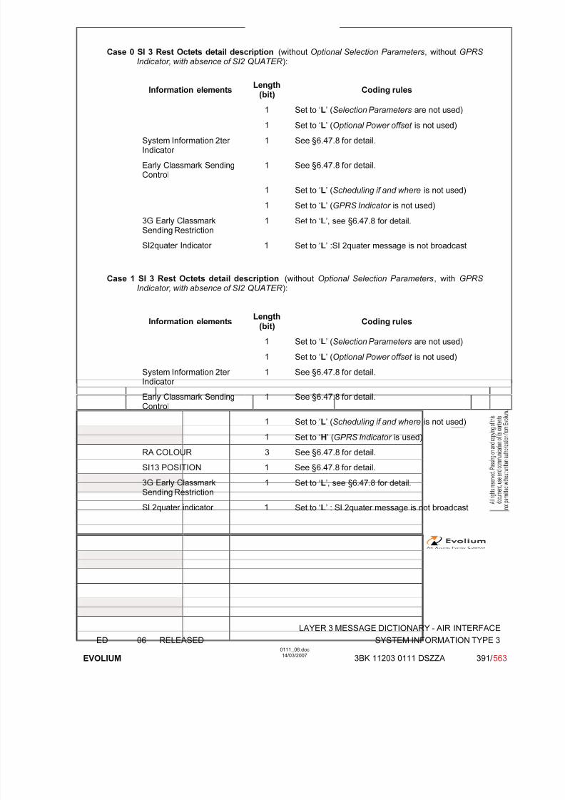
7/11/2019 1. Layer3 Air Interface Messages 0111_06
http://slidepdf.com/reader/full/1-layer3-air-interface-messages-011106 391/562
LAYER 3 MESSAGE DICTIONARY - AIR INTERFACE
ED 06 RELEASED SYSTEM INFORMATION TYPE 3
EVOLIUM
0111_06.doc14/03/2007
3BK 11203 0111 DSZZA 391/ 563
Case 0 SI 3 Rest Octets detail description (without Optional Selection Parameters, without GPRS Indicator, with absence of SI2 QUATER ):
Information elements Length
(bit) Coding rules
1 Set to ‘L’ (Selection Parameters are not used)
1 Set to ‘L’ (Optional Power offset is not used)
System Information 2ter Indicator
1 See §6.47.8 for detail.
Early Classmark SendingControl
1 See §6.47.8 for detail.
1 Set to ‘L’ (Scheduling if and where is not used)
1 Set to ‘L’ (GPRS Indicator is not used)
3G Early ClassmarkSending Restriction
1 Set to ‘L’, see §6.47.8 for detail.
SI2quater Indicator 1 Set to ‘L’ :SI 2quater message is not broadcast
Case 1 SI 3 Rest Octets detail description (without Optional Selection Parameters, with GPRS Indicator, with absence of SI2 QUATER ):
Information elements Length
(bit) Coding rules
1 Set to ‘L’ (Selection Parameters are not used)
1 Set to ‘L’ (Optional Power offset is not used)
System Information 2ter Indicator
1 See §6.47.8 for detail.
Early Classmark SendingControl
1 See §6.47.8 for detail.
1 Set to ‘L’ (Scheduling if and where is not used)
1 Set to ‘H’ (GPRS Indicator is used)
RA COLOUR 3 See §6.47.8 for detail.
SI13 POSITION 1 See §6.47.8 for detail.
3G Early Classmark
Sending Restriction
1 Set to ‘L’, see §6.47.8 for detail.
SI 2quater indicator 1 Set to ‘L’ : SI 2quater message is not broadcast

7/11/2019 1. Layer3 Air Interface Messages 0111_06
http://slidepdf.com/reader/full/1-layer3-air-interface-messages-011106 392/562
LAYER 3 MESSAGE DICTIONARY - AIR INTERFACE
ED 06 RELEASED SYSTEM INFORMATION TYPE 3
EVOLIUM
0111_06.doc14/03/2007
3BK 11203 0111 DSZZA 392/ 563
Case 2 SI 3 Rest Octets detail description (with Optional Selection Parameters, without GPRS Indicator, with absence of SI2 QUATER ):
Information elements Length
(bit) Coding rules
1 Set to ‘H’ (Selection Parameters are used)
CBQ 1 See §6.47.8 for detail.
CELL_RESELECT_OFFSET 6 See §6.47.8 for detail.
TEMPORARY_OFFSET 3 See §6.47.8 for detail.
PENALTY_TIME 5 See §6.47.8 for detail.
1 Set to ‘L’ (Optional Power offset is not used)
System Information 2ter Indicator
1 See §6.47.8 for detail.
Early Classmark SendingControl
1 See §6.47.8 for detail.
1 Set to ‘L’ (Scheduling if and where is not used)
1 Set to ‘L’ (GPRS Indicator is not used)
3G Early ClassmarkSending Restriction
1 Set to ‘L’, see §6.47.8 for detail.
SI 2quater indicator 1 Set to ‘L’ : SI 2quater message is not broadcast

7/11/2019 1. Layer3 Air Interface Messages 0111_06
http://slidepdf.com/reader/full/1-layer3-air-interface-messages-011106 393/562
LAYER 3 MESSAGE DICTIONARY - AIR INTERFACE
ED 06 RELEASED SYSTEM INFORMATION TYPE 3
EVOLIUM
0111_06.doc14/03/2007
3BK 11203 0111 DSZZA 393/ 563
Case 3 SI 3 Rest Octets detail description (with Optional Selection Parameters, with GPRS Indicator, with absence of SI2 QUATER ):
Information elements Length
(bit) Coding rules
1 Set to ‘H’ (Selection Parameters are used)
CBQ 1 See §6.47.8 for detail.
CELL_RESELECT_OFFSET 6 See §6.47.8 for detail.
TEMPORARY_OFFSET 3 See §6.47.8 for detail.
PENALTY_TIME 5 See §6.47.8 for detail.
1 Set to ‘L’ (Optional Power offset is not used)
System Information 2ter Indicator
1 See §6.47.8 for detail.
Early Classmark SendingControl
1 See §6.47.8 for detail.
1 Set to ‘L’ (Scheduling if and where is not used)
1 Set to ‘H’ (GPRS Indicator is used)
RA COLOUR 3 See §6.47.8 for detail.
SI13 POSITION 1 See §6.47.8 for detail.
3G Early ClassmarkSending Restriction
1 Set to ‘L’, see §6.47.8 for detail.
SI 2quater indicator 1 Set to ‘L’ : SI 2quater message is not broadcast

7/11/2019 1. Layer3 Air Interface Messages 0111_06
http://slidepdf.com/reader/full/1-layer3-air-interface-messages-011106 394/562
LAYER 3 MESSAGE DICTIONARY - AIR INTERFACE
ED 06 RELEASED SYSTEM INFORMATION TYPE 3
EVOLIUM
0111_06.doc14/03/2007
3BK 11203 0111 DSZZA 394/ 563
Case 4 SI 3 Rest Octets detail description (with Optional Selection Parameters, with GPRS Indicator, with presence of SI2 QUARTER ).
Information elements Length
(bit) Coding rules
1 Set to ‘H’ (Selection Parameters are used)
CBQ 1 See §6.47.8 for detail.
CELL_RESELECT_OFFSET 6 See §6.47.8 for detail.
TEMPORARY_OFFSET 3 See §6.47.8 for detail.
PENALTY_TIME 5 See §6.47.8 for detail.
1 Set to ‘L’ (Optional Power offset is not used)
System Information 2ter Indicator
1 See §6.47.8 for detail.
Early Classmark SendingControl
1 See §6.47.8 for detail.
1 Set to ‘L’ (Scheduling if and where is not used)
1 Set to ‘H’ (GPRS Indicator is used)
RA COLOUR 3 See §6.47.8 for detail.
SI13 POSITION 1 See §6.47.8 for detail.
3G Early ClassmarkSending Restriction
1 Set to ‘L’, see §6.47.8 for detail.
SI 2quater indicator 1 Set to ‘H’ if SI 2quater message is broadcast
SI2quater_POSITION 1 - 0 : SYSTEM INFORMATION TYPE 2 quater message is sent on BCCH Norm.
- 1 SYSTEM INFORMATION TYPE 2 quater message is sent on BCCH Ext.
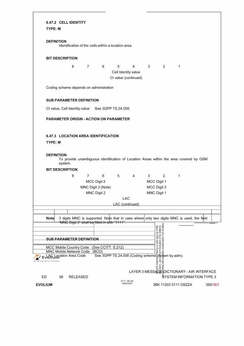
7/11/2019 1. Layer3 Air Interface Messages 0111_06
http://slidepdf.com/reader/full/1-layer3-air-interface-messages-011106 395/562
LAYER 3 MESSAGE DICTIONARY - AIR INTERFACE
ED 06 RELEASED SYSTEM INFORMATION TYPE 3
EVOLIUM
0111_06.doc14/03/2007
3BK 11203 0111 DSZZA 395/ 563
6.47.2 CELL IDENTITY
TYPE: M
DEFINITIONIdentification of the cells within a location area.
BIT DESCRIPTION
8 7 6 5 4 3 2 1
Cell Identity value
CI value (continued)
Coding scheme depends on administration
SUB PARAMETER DEFINITION
CI value, Cell Identity value See 3GPP TS 24.008.
PARAMETER ORIGIN - ACTION ON PARAMETER
6.47.3 LOCATION AREA IDENTIFICATION
TYPE: M
DEFINITION
To provide unambiguous identification of Location Areas within the area covered by GSMsystem.
BIT DESCRIPTION
8 7 6 5 4 3 2 1
MCC Digit 2 MCC Digit 1
MNC Digit 3 (Note) MCC Digit 3
MNC Digit 2 MNC Digit 1
LAC
LAC (continued)
Note 3 digits MNC is supported. Note that in case where only two digits MNC is used, the field“MNC Digit 3” shall be filled in with “1111”.
SUB PARAMETER DEFINITION
MCC Mobile Country Code (See CCITT. E.212)MNC Mobile Network Code (BCD)LAC Location Area Code See 3GPP TS 24.008 (Coding scheme chosen by adm).
7/11/2019 1. Layer3 Air Interface Messages 0111_06
http://slidepdf.com/reader/full/1-layer3-air-interface-messages-011106 396/562
LAYER 3 MESSAGE DICTIONARY - AIR INTERFACE
ED 06 RELEASED SYSTEM INFORMATION TYPE 3
EVOLIUM
0111_06.doc14/03/2007
3BK 11203 0111 DSZZA 396/ 563
PARAMETER ORIGIN - ACTION ON PARAMETER
All these parameters will be given to BSC during the Configuration.

7/11/2019 1. Layer3 Air Interface Messages 0111_06
http://slidepdf.com/reader/full/1-layer3-air-interface-messages-011106 397/562
LAYER 3 MESSAGE DICTIONARY - AIR INTERFACE
ED 06 RELEASED SYSTEM INFORMATION TYPE 3
EVOLIUM
0111_06.doc14/03/2007
3BK 11203 0111 DSZZA 397/ 563
6.47.4 CONTROL CHANNEL DESCRIPTION
TYPE: M
DEFINITIONTo provide a variety of information about a cell
BIT DESCRIPTION
8 7 6 5 4 3 2 1
MSCR ATT BS-AG-BLKS-RES CCCH-CONF
0Spare
0Spare
0Spare
0 0CBQ2
BS-PA-M FRMS
T 3212 Timeout value
bit 8 of octet 1 and bits 4, 5, 6, 7, 8 of octet 2 are spare.
SUB PARAMETER DEFINITION
MSCR, MSC Release. Set by O&M according to the MSC Release.
Bit 8
0 MSC is Release '98 or older 1 MSC is Release '99 onwards
ATT, Attach-detach allowed. Set by O&M according to MSC and VLR options.
Bit 70 MSs in the cell are not allowed to apply IMSI attach and detach procedure.
1 MSs in the cell shall apply IMSI attach and detach procedure.
BS-AG-BLKS-RES,
The BS-AG-BLKS-RES field is coded as the binary representation of the number of blocksreserved for access grant.
Range 0 to 2 if CCCH-CONF = "001"0 to 7 for other values of CCCH-CONF
All other values are reserved in the first case
CCCH-CONF Bits3 2 1
0 0 0 1 basic physical channel used for CCCH, not combined with SDCCHs0 0 1 1 basic physical channel used for CCCH, combined with SDCCHs0 1 0 2 basic physical channel used for CCCH, not combined with SDCCHs1 0 0 3 basic physical channel used for CCCH, not combined with SDCCHs1 1 0 4 basic physical channels used for CCCH, not combined with SDCCHsAll other values are reserved
CBQ2, Cell Bar Qualify 2. Always set to ‘00’Bits5 40 0 Cell Bar Qualify 2 inactive0 1 Reserved, shall be interpreted as 111 0 Voice not supported, cell not barred, norm. cell selection priority1 1 Voice not supported, cell not barred, low cell selection priority
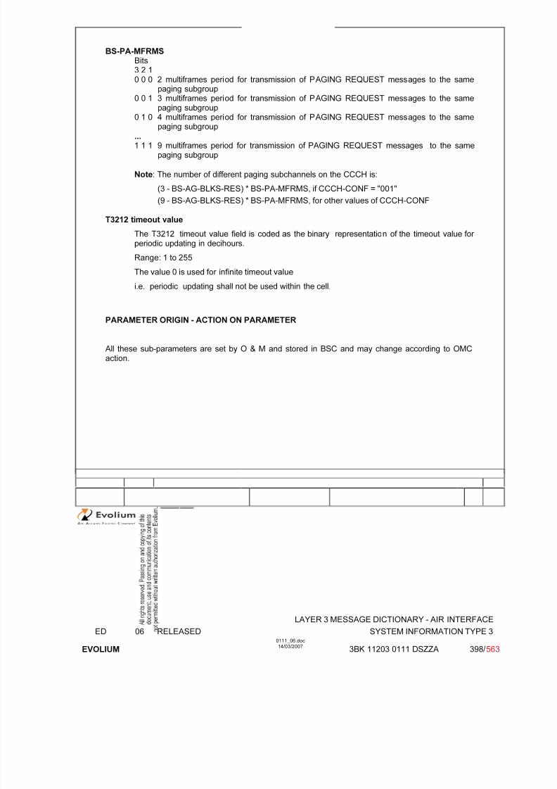
7/11/2019 1. Layer3 Air Interface Messages 0111_06
http://slidepdf.com/reader/full/1-layer3-air-interface-messages-011106 398/562
LAYER 3 MESSAGE DICTIONARY - AIR INTERFACE
ED 06 RELEASED SYSTEM INFORMATION TYPE 3
EVOLIUM
0111_06.doc14/03/2007
3BK 11203 0111 DSZZA 398/ 563
BS-PA-MFRMS Bits3 2 10 0 0 2 multiframes period for transmission of PAGING REQUEST messages to the same
paging subgroup0 0 1 3 multiframes period for transmission of PAGING REQUEST messages to the same
paging subgroup
0 1 0 4 multiframes period for transmission of PAGING REQUEST messages to the samepaging subgroup...1 1 1 9 multiframes period for transmission of PAGING REQUEST messages to the same
paging subgroup
Note: The number of different paging subchannels on the CCCH is:
(3 - BS-AG-BLKS-RES) * BS-PA-MFRMS, if CCCH-CONF = "001"
(9 - BS-AG-BLKS-RES) * BS-PA-MFRMS, for other values of CCCH-CONF
T3212 timeout value
The T3212 timeout value field is coded as the binary representation of the timeout value for
periodic updating in decihours.
Range: 1 to 255
The value 0 is used for infinite timeout value
i.e. periodic updating shall not be used within the cell.
PARAMETER ORIGIN - ACTION ON PARAMETER
All these sub-parameters are set by O & M and stored in BSC and may change according to OMCaction.

7/11/2019 1. Layer3 Air Interface Messages 0111_06
http://slidepdf.com/reader/full/1-layer3-air-interface-messages-011106 399/562
LAYER 3 MESSAGE DICTIONARY - AIR INTERFACE
ED 06 RELEASED SYSTEM INFORMATION TYPE 3
EVOLIUM
0111_06.doc14/03/2007
3BK 11203 0111 DSZZA 399/ 563
6.47.5 CELL OPTIONS (BCCH)
TYPE: M
DEFINITIONTo provide a variety of information about a cell.
BIT DESCRIPTION
8 7 6 5 4 3 2 1
0 PWRC DTX Radio-Link-Timeout
SUB PARAMETER DEFINITION
PWRC : Power control indicator
0 MS shall include measurement on the BCCH carrier. PWRC is not set1 MS shall not include measurement on the BCCH carrier. PWRC is set
DTX : DTX indicator value 00 MS may use discontinuous transmissionvalue 01 MS shall use discontinuous transmissionvalue 10 MS shall not use discontinuous transmission
Radio-Link-Timeout
0000: 4 SACCH blocks0001: 8 SACCH blocks0010: 12 SACCH blocks....
..1110: 60 SACCH blocks1111: 64 SACCH blocks
See 3GPP TS. 05.08
PARAMETER ORIGIN - ACTION ON PARAMETER
Information known by BSC (via O&M operation) and send to MS on BCCH.

7/11/2019 1. Layer3 Air Interface Messages 0111_06
http://slidepdf.com/reader/full/1-layer3-air-interface-messages-011106 400/562
LAYER 3 MESSAGE DICTIONARY - AIR INTERFACE
ED 06 RELEASED SYSTEM INFORMATION TYPE 3
EVOLIUM
0111_06.doc14/03/2007
3BK 11203 0111 DSZZA 400/ 563
6.47.6 CELL SELECTION PARAMETERS
TYPE: M
DEFINITIONTo provide a variety of information about a cell.
BIT DESCRIPTION
8 7 6 5 4 3 2 1
CELL RESELECTHYSTERESIS
MS-TXPWR-MAX-CCH
ACS NECI RXLEV-ACCESS-MIN
SUB PARAMETER DEFINITION
CELL RESELECT HYSTERESIS Bits 8 7 6
0 0 0 0 dB RXLEV hysteresis for LA re-selection0 0 1 2 dB RXLEV hysteresis for LA re-selection0 1 0 4 dB RXLEV hysteresis for LA re-selection0 1 1 6 dB RXLEV hysteresis for LA re-selection1 0 0 8 dB RXLEV hysteresis for LA re-selection1 0 1 10 dB RXLEV hysteresis for LA re-selection1 1 0 12 dB RXLEV hysteresis for LA re-selection1 1 1 14 dB RXLEV hysteresis for LA re-selection
MS-TXPWR-MAX-CCH: binary representation of the maximum power control level
an MS may use when accessing on a CCHGSM 900 coding: range 0 to 19; step size = 2 dBm; 0: 43 dBm, ...,
15: 13 dBm, 19: 5 dBm, see §6.2.4 and §6.20.6for detail.
DCS 1800 coding: range 0 to 15; step size = 2 dBm; 0: 30 dBm, ...,13: 4dBm, 15: 0 dBm, see §6.2.4 and §6.20.6 for detail.
DCS 1900 coding: range 0 to 15, 30, 31; 30: 33 dBm, 31: 32 dBm,0: 30 dBm, 1: 28 dBm, ..., 14: 2dBm, 15: 0 dBm,see §6.2.4 and §6.20.6 for detail.
RXLEV-ACCESS-MIN : binary representation of the minimum received signal level at the MS for
which it is permitted to access the system (value 0 to 63 - 3GPP TS. 05.08)
ACS Additional reselection parameter indication.0 System information type 16 and 17 are not broadcast on the BCCH.1 System information type 16 and 17 are broadcast on the BCCH.
NECI 0 New establishment causes are not supported1 New establishment causes are supported Not supported
PARAMETER ORIGIN - ACTION ON PARAMETER

7/11/2019 1. Layer3 Air Interface Messages 0111_06
http://slidepdf.com/reader/full/1-layer3-air-interface-messages-011106 401/562
LAYER 3 MESSAGE DICTIONARY - AIR INTERFACE
ED 06 RELEASED SYSTEM INFORMATION TYPE 3
EVOLIUM
0111_06.doc14/03/2007
3BK 11203 0111 DSZZA 401/ 563
6.47.7 RACH CONTROL PARAMETER
TYPE: M
DEFINITIONTo provide parameters used to control the RACH utilisation.
BIT DESCRIPTION
8 7 6 5 4 3 2 1
MaxRetrans
TX-Integer CellBar
Acces
RE
ACC15
ACC14
ACC13
ACC12
ACC11
ECC10
ACC09
ACC08
ACC07
ACC06
ACC05
ACC04
ACC03
ACC02
ACC01
ACC00
SUB PARAMETER DEFINITION
Max Retrans 00 1 re transmission01 2 re transmissions10 4 re transmissions11 7 re transmissions
TX Integer Number of time slots to spread transmissionBits 6 5 4 3
0 0 0 0 3 slots used to spread transmission0 0 0 1 4 slots used to spread transmission0 0 1 0 5 slots used to spread transmission0 0 1 1 6 slots used to spread transmission0 1 0 0 7 slots used to spread transmission0 1 0 1 8 slots used to spread transmission0 1 1 0 9 slots used to spread transmission0 1 1 1 10 slots used to spread transmission1 0 0 0 11 slots used to spread transmission1 0 0 1 12 slots used to spread transmission1 0 1 0 14 slots used to spread transmission1 0 1 1 16 slots used to spread transmission1 1 0 0 20 slots used to spread transmission1 1 0 1 25 slots used to spread transmission1 1 1 0 32 slots used to spread transmission1 1 1 1 50 slots used to spread transmission
Cell Bar Access: Cell barred for access0: the cell is not barred.1: the cell is barred.
RE Call Re-establishment allowed0: Re-establishment allowed in the cell1: Re-establishment not allowed in the cell

7/11/2019 1. Layer3 Air Interface Messages 0111_06
http://slidepdf.com/reader/full/1-layer3-air-interface-messages-011106 402/562
LAYER 3 MESSAGE DICTIONARY - AIR INTERFACE
ED 06 RELEASED SYSTEM INFORMATION TYPE 3
EVOLIUM
0111_06.doc14/03/2007
3BK 11203 0111 DSZZA 402/ 563
EC Emergency Call allowed (Octet 2 bit 3)0: Emergency Call allowed in the cell to all MSs1: Emergency Call not allowed in the cell except for the MSs that belong to one of the classes
between 11 to 15
AC CN : Access Control Class N (octet 2 except bit 3) and octet 3.
For a mobile station with AC CN, access is not barredif the AC CN bit is coded with "0" ; N = 0,1..9,11..15.
PARAMETER ORIGIN - ACTION ON PARAMETER
All the parameters are given to BSC during configuration and may be changed with OMC requests or by BSC due to "Overload" or "Reset" actions.
6.47.8 SI 3 REST OCTETS
TYPE: M
DEFINITIONThis IE provides parameters used by the mobile for cell reselection purposes. It also indicates whether GPRS service is supported in the cell.
BIT DESCRIPTION
<SI3 Rest Octet> ::= <Optional selection parameters><Optional Power offset><System Information 2ter Indicator>
<Early Classmark Sending Control><Scheduling if and where>{L | H <GPRS Indicator> }<3G Early Classmark Sending Restriction>{L | H < SI2quater Indicator : < SI2quater Indicator struct > > }<spare padding> ;
<Optional Selection Parameters> ::= L | H <Selection Parameters>;<Selection Parameters> ::=
<CBQ: bit (1)> <CELL_RESELECT_OFFSET : bit (6)>
<TEMPORARY_OFFSET: bit (3)> <PENALTY_TIME: bit (5)>;
<Optional Power Offset> ::= L | H <Power Offset: bit (2)>;<System Information 2ter Indicator> ::= L | H;<Early Classmark Sending Control> ::= L | H;<Scheduling if and where>::= L | H <WHERE: bit (3)>;<GPRS Indicator> ::= < RA COLOUR : bit (3) >
< SI13 POSITION : bit >;<3G Early Classmark Sending Restriction>::= L | H;< SI2quater Indicator struct > ::= L | H < SI2quater_POSITION : bit > ;
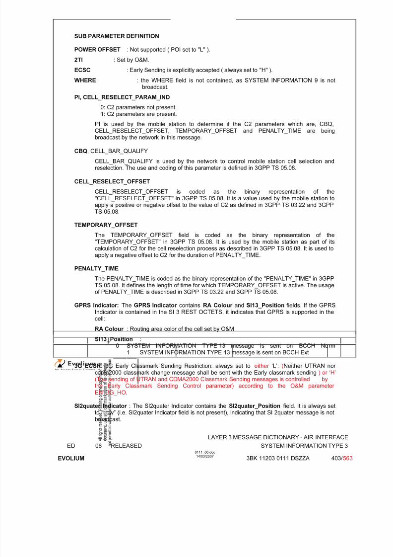
7/11/2019 1. Layer3 Air Interface Messages 0111_06
http://slidepdf.com/reader/full/1-layer3-air-interface-messages-011106 403/562
LAYER 3 MESSAGE DICTIONARY - AIR INTERFACE
ED 06 RELEASED SYSTEM INFORMATION TYPE 3
EVOLIUM
0111_06.doc14/03/2007
3BK 11203 0111 DSZZA 403/ 563
SUB PARAMETER DEFINITION
POWER OFFSET : Not supported ( POI set to "L" ).
2TI : Set by O&M.
ECSC : Early Sending is explicitly accepted ( always set to "H" ).
WHERE : the WHERE field is not contained, as SYSTEM INFORMATION 9 is not
broadcast.
PI, CELL_RESELECT_PARAM_IND
0: C2 parameters not present.1: C2 parameters are present.
PI is used by the mobile station to determine if the C2 parameters which are, CBQ,CELL_RESELECT_OFFSET, TEMPORARY_OFFSET and PENALTY_TIME are beingbroadcast by the network in this message.
CBQ, CELL_BAR_QUALIFY
CELL_BAR_QUALIFY is used by the network to control mobile station cell selection andreselection. The use and coding of this parameter is defined in 3GPP TS 05.08.
CELL_RESELECT_OFFSET
CELL_RESELECT_OFFSET is coded as the binary representation of the"CELL_RESELECT_OFFSET" in 3GPP TS 05.08. It is a value used by the mobile station toapply a positive or negative offset to the value of C2 as defined in 3GPP TS 03.22 and 3GPPTS 05.08.
TEMPORARY_OFFSET
The TEMPORARY_OFFSET field is coded as the binary representation of the"TEMPORARY_OFFSET" in 3GPP TS 05.08. It is used by the mobile station as part of itscalculation of C2 for the cell reselection process as described in 3GPP TS 05.08. It is used to
apply a negative offset to C2 for the duration of PENALTY_TIME.
PENALTY_TIME
The PENALTY_TIME is coded as the binary representation of the "PENALTY_TIME" in 3GPPTS 05.08. It defines the length of time for which TEMPORARY_OFFSET is active. The usageof PENALTY_TIME is described in 3GPP TS 03.22 and 3GPP TS 05.08.
GPRS Indicator: The GPRS Indicator contains RA Colour and SI13_Position fields. If the GPRSIndicator is contained in the SI 3 REST OCTETS, it indicates that GPRS is supported in thecell:
RA Colour : Routing area color of the cell set by O&M
SI13_Position :0 SYSTEM INFORMATION TYPE 13 message is sent on BCCH Norm
1 SYSTEM INFORMATION TYPE 13 message is sent on BCCH Ext
3G ECSR: 3G Early Classmark Sending Restriction: always set to either ‘L’: (Neither UTRAN nor cdma2000 classmark change message shall be sent with the Early classmark sending) or ‘H’(The sending of UTRAN and CDMA2000 Classmark Sending messages is controlled bythe Early Classmark Sending Control parameter) according to the O&M parameter EN_3G_HO.
SI2quater Indicator : The SI2quater Indicator contains the SI2quater_Position field. It is always setto “Low” (i.e. SI2quater Indicator field is not present), indicating that SI 2quater message is notbroadcast.
7/11/2019 1. Layer3 Air Interface Messages 0111_06
http://slidepdf.com/reader/full/1-layer3-air-interface-messages-011106 404/562
LAYER 3 MESSAGE DICTIONARY - AIR INTERFACE
ED 06 RELEASED SYSTEM INFORMATION TYPE 3
EVOLIUM
0111_06.doc14/03/2007
3BK 11203 0111 DSZZA 404/ 563
PARAMETER ORIGIN - ACTION ON PARAMETER

7/11/2019 1. Layer3 Air Interface Messages 0111_06
http://slidepdf.com/reader/full/1-layer3-air-interface-messages-011106 405/562
LAYER 3 MESSAGE DICTIONARY - AIR INTERFACE
ED 06 RELEASED SYSTEM INFORMATION TYPE 4
EVOLIUM
0111_06.doc14/03/2007
3BK 11203 0111 DSZZA 405/ 563
6.48 SYSTEM INFORMATION TYPE 4
NAME SYSTEM INFORMATION TYPE 4
INTERFACE RADIO ABIS A
CHANNEL/ USAGE
BCCH
3GPP-REF 44.018
FUNCTION This message is sent on the BCCH by the network giving information on controlof the RACH, the location area identification, the cell identity and various other information about the cell.
DIRECTION From: BSC To: MS
INFORMATION ELEMENT NAME TYPE COMMENT LENGTH(byte)
INFORMATIONELEMENT
LISTL2 Pseudo LengthHeader Location area ID.Cell Selection Parameters.RACH Control ParametersCBCH channel descriptionCBCH Mobile allocationSI 4 Rest Octets
M V
M V M V M V O TV C TLV M V
125234
3-60-10
IMPLEMENTATION MAXIMUM LENGTH 23
NORMAL SITUATION ABNORMAL SITUATION TIMER
FOLLOWINGEVENT
SPECIFDOC. REF.
BSS Initialisation of the telecom part (ref. [19])System Information Management (ref. [24])

7/11/2019 1. Layer3 Air Interface Messages 0111_06
http://slidepdf.com/reader/full/1-layer3-air-interface-messages-011106 406/562
LAYER 3 MESSAGE DICTIONARY - AIR INTERFACE
ED 06 RELEASED SYSTEM INFORMATION TYPE 4
EVOLIUM
0111_06.doc14/03/2007
3BK 11203 0111 DSZZA 406/ 563
6.48.1 GENERAL DESCRIPTION
8 7 6 5 4 3 2 1
L2 Pseudo Length L2 Pseudo Length Value 0 1
0 0 0 0 0 1 1 00 0 0 1 1 1 0 0
MCC Digit 2 MCC Digit 1
Location Area MNC Digit 3 (Note) MCC Digit 3
Identification MNC Digit 2 MNC Digit 1
LAC
LAC (continued)
Cell selectionParameters
CELL RESELECTHYSTERESIS
MS-TXPWR-MAX-CCH
ACS NECI RXLEV-ACCESS-MIN
Max Retrans TX-Integer Cell
Bar Acces
RE
RACH ControlParameters
ACC15
ACC14
ACC13
ACC12
ACC11
ECACC9
ACC8
ACC7
ACC6
ACC5
ACC4
ACC3
ACC2
ACC1
ACC0
0 1 1 0 0 1 0 0
CBCH ChannelDescription
Channel type and TDMA offset TN
(optional) TSC H=1-> MAIO (high part)
H=0-> spare ARFCN (Hpart)
MAIO low part H S N
A R F C N (low part)
0 1 1 1 0 0 1 0
Length of mobile alloc. contents ≤ 2
CBCH MobileAllocation
MAC8n
MAC
8n-1
MAC
8n-7
(conditional) : :
MAC8
MAC1
SI 4 Rest Octets See the tables below for the detail
Note 3 digits MNC is supported. Note that in case where only two digits MNC is used, the field“MNC Digit 3” shall be filled in with “1111”.

7/11/2019 1. Layer3 Air Interface Messages 0111_06
http://slidepdf.com/reader/full/1-layer3-air-interface-messages-011106 407/562
LAYER 3 MESSAGE DICTIONARY - AIR INTERFACE
ED 06 RELEASED SYSTEM INFORMATION TYPE 4
EVOLIUM
0111_06.doc14/03/2007
3BK 11203 0111 DSZZA 407/ 563
Case 0 SI 4 Rest Octets detail description (without Optional Selection Parameters and GPRS isdisable:
Information elements Length
(bit) Coding rules
1 Set to ‘L’ (Selection Parameters are not used)
1 Set to ‘L’ (Optional Power offset is not used)
1 Set to ‘L’ (GPRS Indicator is not used)
1 Set to ‘L’ (Break indicator is used)
1 Set to ‘L’ or ‘H’ (Break indicator)
Case 1 SI 4 Rest Octets detail description (without Optional Selection Parameters and GPRS isenable:
Information elements Length(bit)
Coding rules
1 Set to ‘L’ (Selection Parameters are not used)
1 Set to ‘L’ (Optional Power offset is not used)
1 Set to ‘H’ (GPRS Indicator is used)
RA COLOUR 3 See §6.48.7 for detail.
SI13 POSITION 1 See §6.48.7 for detail.
1 Set to ‘L’ (Break indicator is used)
1 Set to ‘L’ or ‘H’ (Break indicator)
Case 2 SI 4 Rest Octets detail description (with Optional Selection Parameters and GPRS isdisable:
Information elements Length
(bit) Coding rules
1 Set to ‘H’ (Selection Parameters are used)
CBQ 1 See §6.48.7 for detail.
CELL_RESELECT_OFFSET 6 See §6.48.7 for detail.
TEMPORARY_OFFSET 3 See §6.48.7 for detail.
PENALTY_TIME 5 See §6.48.7 for detail.
1 Set to ‘L’ (Optional Power offset is not used)
1 Set to ‘L’ (GPRS Indicator is not used)
1 Set to ‘L’ (Break indicator is used)
1 Set to ‘L’ or ‘H’ (Break indicator)
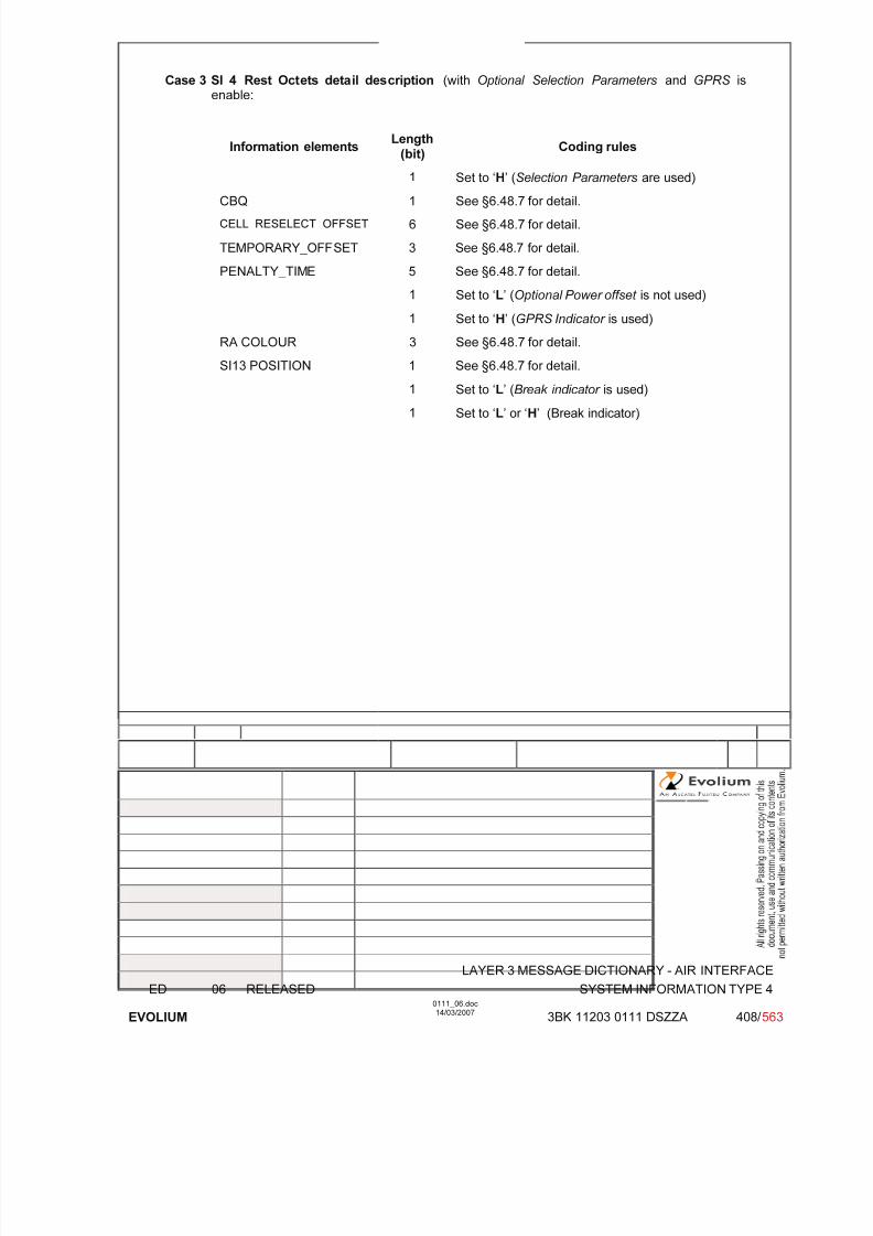
7/11/2019 1. Layer3 Air Interface Messages 0111_06
http://slidepdf.com/reader/full/1-layer3-air-interface-messages-011106 408/562
LAYER 3 MESSAGE DICTIONARY - AIR INTERFACE
ED 06 RELEASED SYSTEM INFORMATION TYPE 4
EVOLIUM
0111_06.doc14/03/2007
3BK 11203 0111 DSZZA 408/ 563
Case 3 SI 4 Rest Octets detail description (with Optional Selection Parameters and GPRS isenable:
Information elements Length
(bit) Coding rules
1 Set to ‘H’ (Selection Parameters are used)
CBQ 1 See §6.48.7 for detail.
CELL_RESELECT_OFFSET 6 See §6.48.7 for detail.
TEMPORARY_OFFSET 3 See §6.48.7 for detail.
PENALTY_TIME 5 See §6.48.7 for detail.
1 Set to ‘L’ (Optional Power offset is not used)
1 Set to ‘H’ (GPRS Indicator is used)
RA COLOUR 3 See §6.48.7 for detail.
SI13 POSITION 1 See §6.48.7 for detail.
1 Set to ‘L’ (Break indicator is used)
1 Set to ‘L’ or ‘H’ (Break indicator)
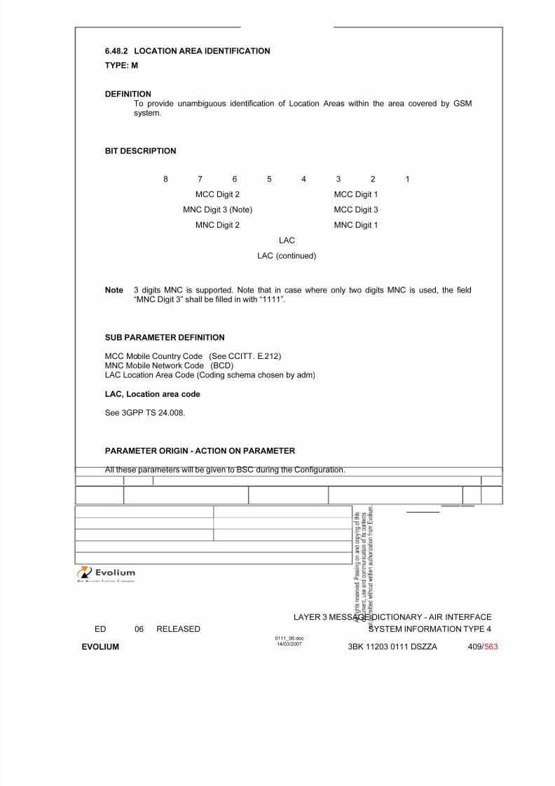
7/11/2019 1. Layer3 Air Interface Messages 0111_06
http://slidepdf.com/reader/full/1-layer3-air-interface-messages-011106 409/562
LAYER 3 MESSAGE DICTIONARY - AIR INTERFACE
ED 06 RELEASED SYSTEM INFORMATION TYPE 4
EVOLIUM
0111_06.doc14/03/2007
3BK 11203 0111 DSZZA 409/ 563
6.48.2 LOCATION AREA IDENTIFICATION
TYPE: M
DEFINITIONTo provide unambiguous identification of Location Areas within the area covered by GSMsystem.
BIT DESCRIPTION
8 7 6 5 4 3 2 1
MCC Digit 2 MCC Digit 1
MNC Digit 3 (Note) MCC Digit 3
MNC Digit 2 MNC Digit 1
LAC
LAC (continued)
Note 3 digits MNC is supported. Note that in case where only two digits MNC is used, the field“MNC Digit 3” shall be filled in with “1111”.
SUB PARAMETER DEFINITION
MCC Mobile Country Code (See CCITT. E.212)
MNC Mobile Network Code (BCD)LAC Location Area Code (Coding schema chosen by adm)
LAC, Location area code
See 3GPP TS 24.008.
PARAMETER ORIGIN - ACTION ON PARAMETER
All these parameters will be given to BSC during the Configuration.
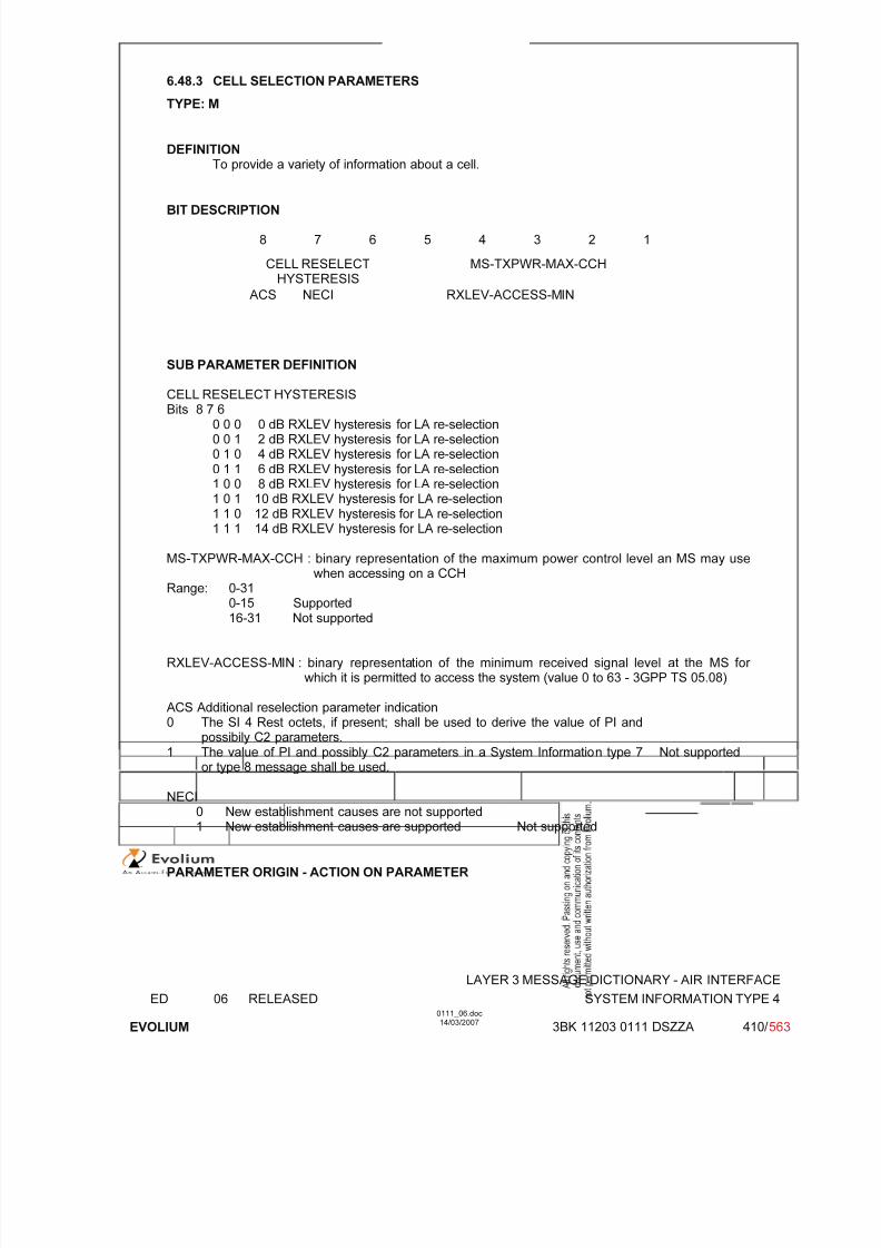
7/11/2019 1. Layer3 Air Interface Messages 0111_06
http://slidepdf.com/reader/full/1-layer3-air-interface-messages-011106 410/562
LAYER 3 MESSAGE DICTIONARY - AIR INTERFACE
ED 06 RELEASED SYSTEM INFORMATION TYPE 4
EVOLIUM
0111_06.doc14/03/2007
3BK 11203 0111 DSZZA 410/ 563
6.48.3 CELL SELECTION PARAMETERS
TYPE: M
DEFINITIONTo provide a variety of information about a cell.
BIT DESCRIPTION
8 7 6 5 4 3 2 1
CELL RESELECTHYSTERESIS
MS-TXPWR-MAX-CCH
ACS NECI RXLEV-ACCESS-MIN
SUB PARAMETER DEFINITION
CELL RESELECT HYSTERESISBits 8 7 6
0 0 0 0 dB RXLEV hysteresis for LA re-selection0 0 1 2 dB RXLEV hysteresis for LA re-selection0 1 0 4 dB RXLEV hysteresis for LA re-selection0 1 1 6 dB RXLEV hysteresis for LA re-selection1 0 0 8 dB RXLEV hysteresis for LA re-selection1 0 1 10 dB RXLEV hysteresis for LA re-selection1 1 0 12 dB RXLEV hysteresis for LA re-selection1 1 1 14 dB RXLEV hysteresis for LA re-selection
MS-TXPWR-MAX-CCH : binary representation of the maximum power control level an MS may use
when accessing on a CCHRange: 0-31
0-15 Supported16-31 Not supported
RXLEV-ACCESS-MIN : binary representation of the minimum received signal level at the MS for which it is permitted to access the system (value 0 to 63 - 3GPP TS 05.08)
ACS Additional reselection parameter indication0 The SI 4 Rest octets, if present; shall be used to derive the value of PI and
possibily C2 parameters.1 The value of PI and possibly C2 parameters in a System Information type 7
or type 8 message shall be used.
Not supported
NECI0 New establishment causes are not supported1 New establishment causes are supported Not supported
PARAMETER ORIGIN - ACTION ON PARAMETER

7/11/2019 1. Layer3 Air Interface Messages 0111_06
http://slidepdf.com/reader/full/1-layer3-air-interface-messages-011106 411/562
LAYER 3 MESSAGE DICTIONARY - AIR INTERFACE
ED 06 RELEASED SYSTEM INFORMATION TYPE 4
EVOLIUM
0111_06.doc14/03/2007
3BK 11203 0111 DSZZA 411/ 563
6.48.4 RACH CONTROL PARAMETER
TYPE: M
DEFINITIONTo provide parameters used to control the RACH utilisation.
BIT DESCRIPTION
8 7 6 5 4 3 2 1
MaxRetrans
TX-Integer CellBar
Acces
RE
ACC15
ACC14
ACC13
ACC12
ACC11
ECC10
ACC09
ACC08
ACC07
ACC06
ACC05
ACC04
ACC03
ACC02
ACC01
ACC00
SUB PARAMETER DEFINITION
Max Retrans 00 1 re transmission01 2 re transmissions10 4 re transmissions11 7 re transmissions
TX Integer Number of time slots to spread transmissionBits 6 5 4 3
0 0 0 0 3 slots used to spread transmission0 0 0 1 4 slots used to spread transmission
0 0 1 0 5 slots used to spread transmission0 0 1 1 6 slots used to spread transmission0 1 0 0 7 slots used to spread transmission0 1 0 1 8 slots used to spread transmission0 1 1 0 9 slots used to spread transmission0 1 1 1 10 slots used to spread transmission1 0 0 0 11 slots used to spread transmission1 0 0 1 12 slots used to spread transmission1 0 1 0 14 slots used to spread transmission1 0 1 1 16 slots used to spread transmission1 1 0 0 20 slots used to spread transmission1 1 0 1 25 slots used to spread transmission1 1 1 0 32 slots used to spread transmission1 1 1 1 50 slots used to spread transmission
Cell Bar Access: Cell barred for access0: the cell is not barred.1: the cell is barred.
RE Call Re-establishment allowed0: Re-establishment allowed in the cell1: Re-establishment not allowed in the cell
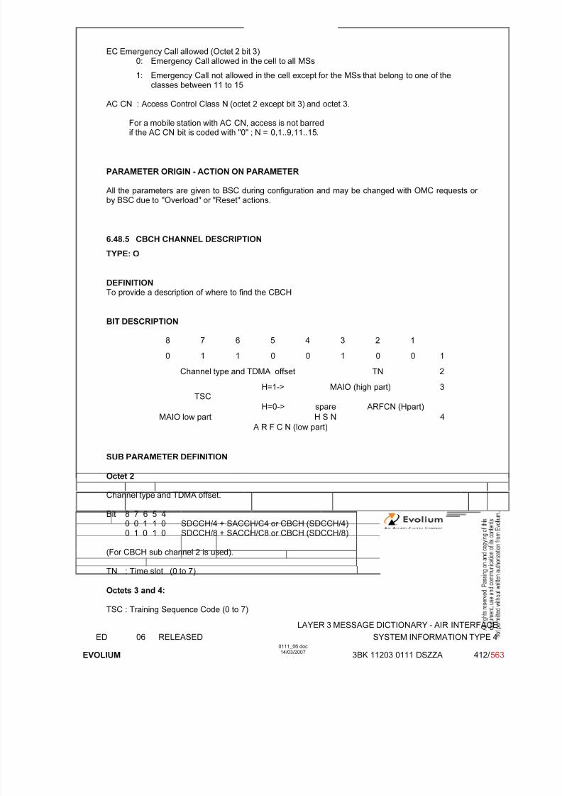
7/11/2019 1. Layer3 Air Interface Messages 0111_06
http://slidepdf.com/reader/full/1-layer3-air-interface-messages-011106 412/562
LAYER 3 MESSAGE DICTIONARY - AIR INTERFACE
ED 06 RELEASED SYSTEM INFORMATION TYPE 4
EVOLIUM
0111_06.doc14/03/2007
3BK 11203 0111 DSZZA 412/ 563
EC Emergency Call allowed (Octet 2 bit 3)0: Emergency Call allowed in the cell to all MSs
1: Emergency Call not allowed in the cell except for the MSs that belong to one of theclasses between 11 to 15
AC CN : Access Control Class N (octet 2 except bit 3) and octet 3.
For a mobile station with AC CN, access is not barredif the AC CN bit is coded with "0" ; N = 0,1..9,11..15.
PARAMETER ORIGIN - ACTION ON PARAMETER
All the parameters are given to BSC during configuration and may be changed with OMC requests or by BSC due to "Overload" or "Reset" actions.
6.48.5 CBCH CHANNEL DESCRIPTION
TYPE: O
DEFINITIONTo provide a description of where to find the CBCH
BIT DESCRIPTION
8 7 6 5 4 3 2 1
0 1 1 0 0 1 0 0 1
Channel type and TDMA offset TN 2
TSCH=1-> MAIO (high part) 3
H=0-> spare ARFCN (Hpart)
MAIO low part H S N 4
A R F C N (low part)
SUB PARAMETER DEFINITION
Octet 2
Channel type and TDMA offset.
Bit 8 7 6 5 40 0 1 1 0 SDCCH/4 + SACCH/C4 or CBCH (SDCCH/4)0 1 0 1 0 SDCCH/8 + SACCH/C8 or CBCH (SDCCH/8)
(For CBCH sub channel 2 is used).
TN : Time slot (0 to 7)
Octets 3 and 4:
TSC : Training Sequence Code (0 to 7)
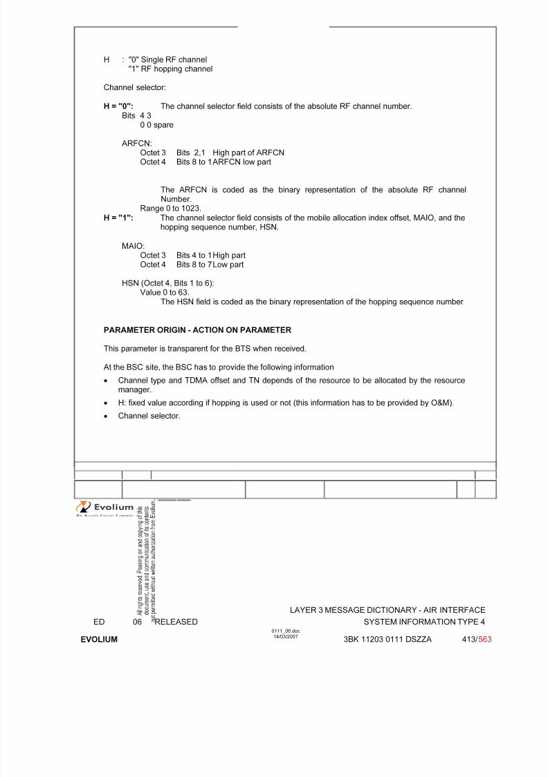
7/11/2019 1. Layer3 Air Interface Messages 0111_06
http://slidepdf.com/reader/full/1-layer3-air-interface-messages-011106 413/562
LAYER 3 MESSAGE DICTIONARY - AIR INTERFACE
ED 06 RELEASED SYSTEM INFORMATION TYPE 4
EVOLIUM
0111_06.doc14/03/2007
3BK 11203 0111 DSZZA 413/ 563
H : "0" Single RF channel"1" RF hopping channel
Channel selector:
H = "0": The channel selector field consists of the absolute RF channel number.
Bits 4 30 0 spare
ARFCN:Octet 3 Bits 2,1 High part of ARFCNOctet 4 Bits 8 to 1 ARFCN low part
The ARFCN is coded as the binary representation of the absolute RF channelNumber.
Range 0 to 1023.H = "1": The channel selector field consists of the mobile allocation index offset, MAIO, and the
hopping sequence number, HSN.
MAIO:Octet 3 Bits 4 to 1 High partOctet 4 Bits 8 to 7 Low part
HSN (Octet 4, Bits 1 to 6):Value 0 to 63.
The HSN field is coded as the binary representation of the hopping sequence number.
PARAMETER ORIGIN - ACTION ON PARAMETER
This parameter is transparent for the BTS when received.
At the BSC site, the BSC has to provide the following information
• Channel type and TDMA offset and TN depends of the resource to be allocated by the resourcemanager.
• H: fixed value according if hopping is used or not (this information has to be provided by O&M).
• Channel selector.

7/11/2019 1. Layer3 Air Interface Messages 0111_06
http://slidepdf.com/reader/full/1-layer3-air-interface-messages-011106 414/562
LAYER 3 MESSAGE DICTIONARY - AIR INTERFACE
ED 06 RELEASED SYSTEM INFORMATION TYPE 4
EVOLIUM
0111_06.doc14/03/2007
3BK 11203 0111 DSZZA 414/ 563
6.48.6 CBCH MOBILE ALLOCATION
TYPE: C
DEFINITIONIf the CBCH channel description indicates frequency hopping, then this IE is always present.
BIT DESCRIPTION
8 7 6 5 4 3 2 1
0 1 1 1 0 0 1 0
Length of mobile alloc. contents ≤ 2
MAC8n
MAC
8n-1
MAC
8n-7
: :
MAC8
MAC1
SUB PARAMETER DEFINITION
MA length depends on the relative frequency span of the frequencies in the cell allocation frequencylist.
MA Ci: Mobile Allocation RF channel i - the RF channels represented in the MA Ci bit fields arethose which in the cell channel description information element are coded with "1" in the CA
ARFCN N bit fields.
MA Ci = CA ARFCN N(i) i = 1,2...NF(NF = Number of Frequencies in the CA frequency list).
For a RF channel belonging to the Mobile Allocation the MA Ci bit is coded with a "1",for a RF channel not belonging to the Mobile Allocation, the MA C bit is coded with a "0".
PARAMETER ORIGIN - ACTION ON PARAMETER
The parameter is transparent for the BTS when received from the BSC.
Note: Conditional message, if Frequency Hopping system is used, then IE is present else not.
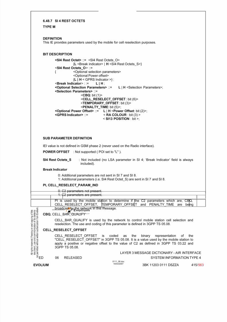
7/11/2019 1. Layer3 Air Interface Messages 0111_06
http://slidepdf.com/reader/full/1-layer3-air-interface-messages-011106 415/562
LAYER 3 MESSAGE DICTIONARY - AIR INTERFACE
ED 06 RELEASED SYSTEM INFORMATION TYPE 4
EVOLIUM
0111_06.doc14/03/2007
3BK 11203 0111 DSZZA 415/ 563
6.48.7 SI 4 REST OCTETS
TYPE M
DEFINITIONThis IE provides parameters used by the mobile for cell reselection purposes.
BIT DESCRIPTION
<SI4 Rest Octet> ::= <SI4 Rest Octets_O>{L <Break indicator> | H <SI4 Rest Octets_S>}
<SI4 Rest Octets_O> ::={ <Optional selection parameters>
<Optional Power offset>{L | H < GPRS Indicator >} ;
<Break Indicator > : := L | H ; <Optional Selection Parameters> ::= L | H <Selection Parameters>;<Selection Parameters> ::=
<CBQ: bit (1)>
<CELL_RESELECT_OFFSET : bit (6)> <TEMPORARY_OFFSET: bit (3)> <PENALTY_TIME: bit (5)>;
<Optional Power Offset> ::= L | H <Power Offset: bit (2)>;<GPRS Indicator> ::= < RA COLOUR : bit (3) >
< SI13 POSITION : bit >;
SUB PARAMETER DEFINITION
IEI value is not defined in GSM phase 2 (never used on the Radio interface).
POWER OFFSET : Not supported ( POI set to "L" ).
SI4 Rest Octets_S : Not included (no LSA parameter in SI 4; ‘Break Indicator’ field is alwaysincluded).
Break Indicator
0: Additional parameters are not sent in SI 7 and SI 8.1: Additional parameters (i.e. SI4 Rest Octet_S) are sent in SI 7 and SI 8.
PI, CELL_RESELECT_PARAM_IND
0: C2 parameters not present.1: C2 parameters are present.
PI is used by the mobile station to determine if the C2 parameters which are, CBQ,CELL_RESELECT_OFFSET, TEMPORARY_OFFSET and PENALTY_TIME are beingbroadcast by the network in this message.
CBQ, CELL_BAR_QUALIFY
CELL_BAR_QUALIFY is used by the network to control mobile station cell selection andreselection. The use and coding of this parameter is defined in 3GPP TS 05.08.
CELL_RESELECT_OFFSET
CELL_RESELECT_OFFSET is coded as the binary representation of the"CELL_RESELECT_OFFSET" in 3GPP TS 05.08. It is a value used by the mobile station toapply a positive or negative offset to the value of C2 as defined in 3GPP TS 03.22 and
3GPP TS 05.08.

7/11/2019 1. Layer3 Air Interface Messages 0111_06
http://slidepdf.com/reader/full/1-layer3-air-interface-messages-011106 416/562
LAYER 3 MESSAGE DICTIONARY - AIR INTERFACE
ED 06 RELEASED SYSTEM INFORMATION TYPE 4
EVOLIUM
0111_06.doc14/03/2007
3BK 11203 0111 DSZZA 416/ 563
TEMPORARY_OFFSET
The TEMPORARY_OFFSET field is coded as the binary representation of the"TEMPORARY_OFFSET" in 3GPP TS 05.08. It is used by the mobile station as part of itscalculation of C2 for the cell reselection process as described in 3GPP TS 05.08. It is used toapply a negative offset to C2 for the duration of PENALTY_TIME.
PENALTY_TIME
The PENALTY_TIME is coded as the binary representation of the "PENALTY_TIME" in3GPP TS 05.08. It defines the length of time for which TEMPORARY_OFFSET is active. Theusage of PENALTY_TIME is described in 3GPP TS 03.22 and 3GPP TS 05.08.
GPRS Indicator: The GPRS Indicator contains RA Colour and SI13_Position fields. If the GPRSIndicator is contained in the SI 4 REST OCTETS, it indicates that GPRS is supported in thecell:
RA Colour : Routing area color of the cell set by O&M
SI13_Position :0 SYSTEM INFORMATION TYPE 13 message is sent on BCCH Norm1 SYSTEM INFORMATION TYPE 13 message is sent on BCCH Ext
PARAMETER ORIGIN - ACTION ON PARAMETER
The CBQ and RACH control parameters are given to the BSC during configuration and may bechanged with OMC requests and may be modified by the BSC during "Overload" or "Reset" actions.

7/11/2019 1. Layer3 Air Interface Messages 0111_06
http://slidepdf.com/reader/full/1-layer3-air-interface-messages-011106 417/562
LAYER 3 MESSAGE DICTIONARY - AIR INTERFACE
ED 06 RELEASED SYSTEM INFORMATION TYPE 5
EVOLIUM
0111_06.doc14/03/2007
3BK 11203 0111 DSZZA 417/ 563
6.49 SYSTEM INFORMATION TYPE 5
NAME SYSTEM INFORMATION TYPE 5
INTERFACE RADIO ABIS A
CHANNEL/ USAGE
SACCH
3GPP-REF 44.018
FUNCTION This message is sent on the SACCH by the network to stations within the cellgiving information on the BCCH allocation in the neighbour cells.
DIRECTION From: BTS To: MS
INFORMATION ELEMENT NAME TYPE COMMENT LENGTH(byte)
INFORMATIONELEMENT
LISTHeader BCCH Frequency List(Note) M V
216
IMPLEMENTATION MAXIMUM LENGTH 18
NORMAL SITUATION ABNORMAL SITUATION TIMER
FOLLOWINGEVENT
SPECIFDOC. REF.
BSS Initialisation of the telecom part (ref. [19])
Note: In case of VGCS,
• if only SI5 is sent by the BSS;
• or if SI5bis is also sent by the BSS but the BCCH frequency of the serving cell is not includedin SI5bis;
then the BCCH Frequency List MIE shall include the BCCH frequency of the serving cell (see 3GPPTS 43.022, section 5.2.1).

7/11/2019 1. Layer3 Air Interface Messages 0111_06
http://slidepdf.com/reader/full/1-layer3-air-interface-messages-011106 418/562
LAYER 3 MESSAGE DICTIONARY - AIR INTERFACE
ED 06 RELEASED SYSTEM INFORMATION TYPE 5
EVOLIUM
0111_06.doc14/03/2007
3BK 11203 0111 DSZZA 418/ 563
6.49.1 GENERAL DESCRIPTION
P-GSM
8 7 6 5 4 3 2 1
0 0 0 0 0 1 1 0
0 0 0 1 1 1 0 1
0 0FORMAT-ID
EXT-IND
BA-IND BAARFCN
124
BAARFCN
123
BAARFCN
122
BAARFCN
121
BCCH BAARFCN
120
BAARFCN
119
BAARFCN
118
BAARFCN
117
BAARFCN
116
BAARFCN
115
BAARFCN
114
BAARFCN
113
Frequency ................
List BAARFCN
8
BAARFCN
7
BAARFCN
6
BAARFCN
5
BAARFCN
4
BAARFCN
3
BAARFCN
2
BAARFCN
1
E-GSM, GSM850, DCS1800, DCS1900 and Biband
8 7 6 5 4 3 2 1
0 0 0 0 0 1 1 0
0 0 0 1 1 1 0 1
1 0FORMAT-ID
EXT-IND
BA-INDFORMAT-ID
(continued) Note
ORIG-ARFCN
high
BCCH ORIG-ARFCN (middle part)
FrequencyList
ORIG-ARFCN
(low)
RRFCN1
RRFCN2
RRFCN3
RRFCN4
RRFCN5
RRFCN6
RRFCN7
: :
RRFCN104
RRFCN105
RRFCN106
RRFCN107
RRFCN108
RRFCN109
RRFCN110
RRFCN111
Note: 0 x x: Range 1024 format;
1 0 0: Range 512 format;1 0 1: Range 256 format;1 1 0: Range 128 format;1 1 1: Variable bit map.

7/11/2019 1. Layer3 Air Interface Messages 0111_06
http://slidepdf.com/reader/full/1-layer3-air-interface-messages-011106 419/562
LAYER 3 MESSAGE DICTIONARY - AIR INTERFACE
ED 06 RELEASED SYSTEM INFORMATION TYPE 5
EVOLIUM
0111_06.doc14/03/2007
3BK 11203 0111 DSZZA 419/ 563
6.49.2 BCCH FREQUENCY LIST / NEIGHBOUR CELLS DESCRIPTION
TYPE: M
DEFINITIONTo provide the absolute radio frequency channel numbers of the BCCH carriers to bemonitored by the MS in the cell.
Used in this case for handover purposes.
BIT DESCRIPTION
Bitmap 0 Format supported for P-GSM.
8 7 6 5 4 3 2 1
0 0FORMAT-ID
EXT-IND
BA-IND BAARFCN
124
BAARFCN
123
BAARFCN
122
BAARFCN
121
1
BAARFCN
120
BAARFCN
119
BAARFCN
118
BAARFCN
117
BAARFCN
116
BAARFCN
115
BAARFCN
114
BAARFCN
113
2
................
BAARFCN
008
BAARFCN
007
BAARFCN
006
BAARFCN
005
BAARFCN
004
BAARFCN
003
BAARFCN
002
BAARFCN
001
16
SUB PARAMETER DEFINITION
FORMAT-ID : Format identifier.
EXT-IND : Extension Indication0 IE carries the complete BA1 IE carries a part of the BA
BA-IND : BCCH allocation sequence number indicationRange 0 to 1.
BA ARFCN N : BCCH Allocation Absolute RF Channel Number N- if ARFCN = N belongs to the BCCH allocation,
BA ARFCN N bit is coded with "1"
N = 1,2 ... 124- if not BA ARFCN N bit is coded with "0" ;
N=1,2 ...124(Note: the number of neighbour BCCH frequencies is limited to 32)
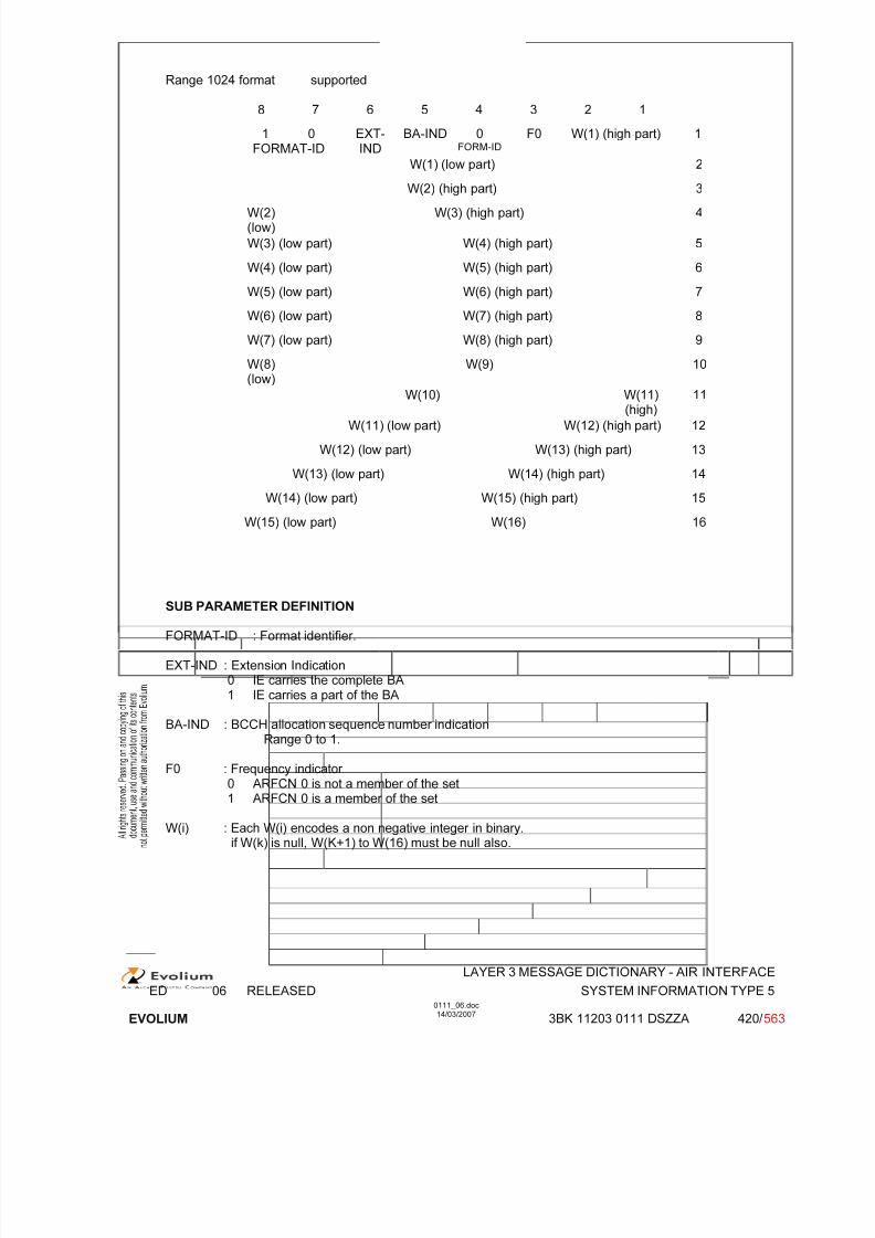
7/11/2019 1. Layer3 Air Interface Messages 0111_06
http://slidepdf.com/reader/full/1-layer3-air-interface-messages-011106 420/562
LAYER 3 MESSAGE DICTIONARY - AIR INTERFACE
ED 06 RELEASED SYSTEM INFORMATION TYPE 5
EVOLIUM
0111_06.doc14/03/2007
3BK 11203 0111 DSZZA 420/ 563
Range 1024 format supported
8 7 6 5 4 3 2 1
1 0FORMAT-ID
EXT-IND
BA-IND 0FORM-ID
F0 W(1) (high part) 1
W(1) (low part) 2
W(2) (high part) 3
W(2)(low)
W(3) (high part) 4
W(3) (low part) W(4) (high part) 5
W(4) (low part) W(5) (high part) 6
W(5) (low part) W(6) (high part) 7
W(6) (low part) W(7) (high part) 8
W(7) (low part) W(8) (high part) 9
W(8)
(low)
W(9) 10
W(10) W(11)(high)
11
W(11) (low part) W(12) (high part) 12
W(12) (low part) W(13) (high part) 13
W(13) (low part) W(14) (high part) 14
W(14) (low part) W(15) (high part) 15
W(15) (low part) W(16) 16
SUB PARAMETER DEFINITION
FORMAT-ID : Format identifier.
EXT-IND : Extension Indication0 IE carries the complete BA1 IE carries a part of the BA
BA-IND : BCCH allocation sequence number indicationRange 0 to 1.
F0 : Frequency indicator 0 ARFCN 0 is not a member of the set1 ARFCN 0 is a member of the set
W(i) : Each W(i) encodes a non negative integer in binary.if W(k) is null, W(K+1) to W(16) must be null also.
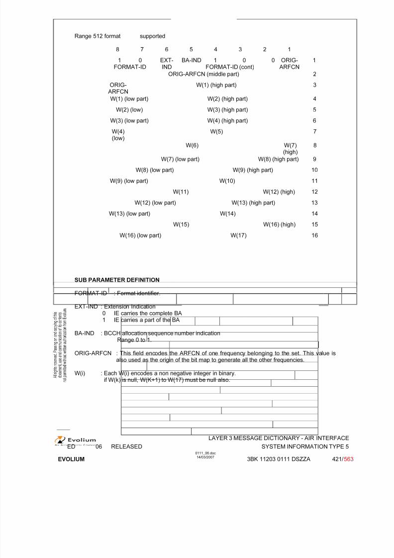
7/11/2019 1. Layer3 Air Interface Messages 0111_06
http://slidepdf.com/reader/full/1-layer3-air-interface-messages-011106 421/562
LAYER 3 MESSAGE DICTIONARY - AIR INTERFACE
ED 06 RELEASED SYSTEM INFORMATION TYPE 5
EVOLIUM
0111_06.doc14/03/2007
3BK 11203 0111 DSZZA 421/ 563
Range 512 format supported
8 7 6 5 4 3 2 1
1 0FORMAT-ID
EXT-IND
BA-IND 1 0 0FORMAT-ID (cont)
ORIG-ARFCN
1
ORIG-ARFCN (middle part) 2
ORIG-ARFCN
W(1) (high part) 3
W(1) (low part) W(2) (high part) 4
W(2) (low) W(3) (high part) 5
W(3) (low part) W(4) (high part) 6
W(4)(low)
W(5) 7
W(6) W(7)(high)
8
W(7) (low part) W(8) (high part) 9
W(8) (low part) W(9) (high part) 10
W(9) (low part) W(10) 11
W(11) W(12) (high) 12
W(12) (low part) W(13) (high part) 13
W(13) (low part) W(14) 14
W(15) W(16) (high) 15
W(16) (low part) W(17) 16
SUB PARAMETER DEFINITION
FORMAT-ID : Format identifier.
EXT-IND : Extension Indication0 IE carries the complete BA1 IE carries a part of the BA
BA-IND : BCCH allocation sequence number indicationRange 0 to 1.
ORIG-ARFCN : This field encodes the ARFCN of one frequency belonging to the set. This value isalso used as the origin of the bit map to generate all the other frequencies.
W(i) : Each W(i) encodes a non negative integer in binary.if W(k) is null, W(K+1) to W(17) must be null also.
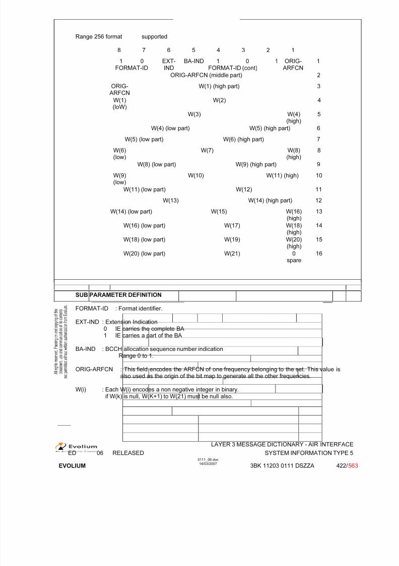
7/11/2019 1. Layer3 Air Interface Messages 0111_06
http://slidepdf.com/reader/full/1-layer3-air-interface-messages-011106 422/562
LAYER 3 MESSAGE DICTIONARY - AIR INTERFACE
ED 06 RELEASED SYSTEM INFORMATION TYPE 5
EVOLIUM
0111_06.doc14/03/2007
3BK 11203 0111 DSZZA 422/ 563
Range 256 format supported
8 7 6 5 4 3 2 1
1 0FORMAT-ID
EXT-IND
BA-IND 1 0 1FORMAT-ID (cont)
ORIG-ARFCN
1
ORIG-ARFCN (middle part) 2
ORIG-ARFCN
W(1) (high part) 3
W(1)(loW)
W(2) 4
W(3) W(4)(high)
5
W(4) (low part) W(5) (high part) 6
W(5) (low part) W(6) (high part) 7
W(6)(low)
W(7) W(8)(high)
8
W(8) (low part) W(9) (high part) 9
W(9)(low)
W(10) W(11) (high) 10
W(11) (low part) W(12) 11
W(13) W(14) (high part) 12
W(14) (low part) W(15) W(16)(high)
13
W(16) (low part) W(17) W(18)(high)
14
W(18) (low part) W(19) W(20)(high)
15
W(20) (low part) W(21) 0
spare
16
SUB PARAMETER DEFINITION
FORMAT-ID : Format identifier.
EXT-IND : Extension Indication0 IE carries the complete BA1 IE carries a part of the BA
BA-IND : BCCH allocation sequence number indicationRange 0 to 1.
ORIG-ARFCN : This field encodes the ARFCN of one frequency belonging to the set. This value isalso used as the origin of the bit map to generate all the other frequencies.
W(i) : Each W(i) encodes a non negative integer in binary.if W(k) is null, W(K+1) to W(21) must be null also.

7/11/2019 1. Layer3 Air Interface Messages 0111_06
http://slidepdf.com/reader/full/1-layer3-air-interface-messages-011106 423/562
LAYER 3 MESSAGE DICTIONARY - AIR INTERFACE
ED 06 RELEASED SYSTEM INFORMATION TYPE 5
EVOLIUM
0111_06.doc14/03/2007
3BK 11203 0111 DSZZA 423/ 563
Range 128 format supported
8 7 6 5 4 3 2 1
1 0FORMAT-ID
EXT-IND
BA-IND 1 1 1FORMAT-ID (cont)
ORIG-ARFCN
1
ORIG-ARFCN (middle part) 2
ORIG-ARFCN
W(1) 3
W(2) W(3) (high part) 4
W(3) (low part) W(4) (high part) 5
W(4)(low)
W(5) W(6) (high part) 6
W(6) (low part) W(7) 7
W(8) W(9) 8
W(10) W(11) 9
W(12) W(13) 10
W(14) W(15) 11
W(16) W(17) W(18) (high) 12
W(18)(low)
W(19) W(20) W(21)(high)
13
W(21) (low) W(22) W(23) 14
W(24) W(25) W(26) (high) 15
W(26)(low)
W(27) W(28) 0spare
16
SUB PARAMETER DEFINITION
FORMAT-ID : Format identifier.
EXT-IND : Extension Indication0 IE carries the complete BA1 IE carries a part of the BA
BA-IND : BCCH allocation sequence number indicationRange 0 to 1.
ORIG-ARFCN : This field encodes the ARFCN of one frequency belonging to the set. This value isalso used as the origin of the bit map to generate all the other frequencies.
W(i) : Each W(i) encodes a non negative integer in binary.if W(k) is null, W(K+1) to W(28) must be null also.
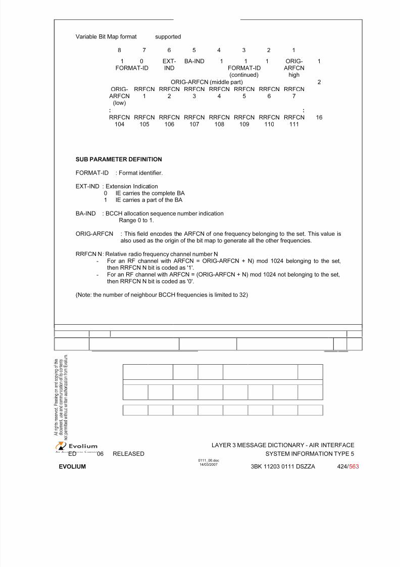
7/11/2019 1. Layer3 Air Interface Messages 0111_06
http://slidepdf.com/reader/full/1-layer3-air-interface-messages-011106 424/562
LAYER 3 MESSAGE DICTIONARY - AIR INTERFACE
ED 06 RELEASED SYSTEM INFORMATION TYPE 5
EVOLIUM
0111_06.doc14/03/2007
3BK 11203 0111 DSZZA 424/ 563
Variable Bit Map format supported
8 7 6 5 4 3 2 1
1 0FORMAT-ID
EXT-IND
BA-IND 1 1 1FORMAT-ID(continued)
ORIG-ARFCN
high
1
ORIG-ARFCN (middle part) 2
ORIG-ARFCN
(low)
RRFCN1
RRFCN2
RRFCN3
RRFCN4
RRFCN5
RRFCN6
RRFCN7
: :
RRFCN104
RRFCN105
RRFCN106
RRFCN107
RRFCN108
RRFCN109
RRFCN110
RRFCN111
16
SUB PARAMETER DEFINITION
FORMAT-ID : Format identifier.
EXT-IND : Extension Indication0 IE carries the complete BA1 IE carries a part of the BA
BA-IND : BCCH allocation sequence number indicationRange 0 to 1.
ORIG-ARFCN : This field encodes the ARFCN of one frequency belonging to the set. This value isalso used as the origin of the bit map to generate all the other frequencies.
RRFCN N : Relative radio frequency channel number N
- For an RF channel with ARFCN = ORIG-ARFCN + N) mod 1024 belonging to the set,then RRFCN N bit is coded as '1'.
- For an RF channel with ARFCN = (ORIG-ARFCN + N) mod 1024 not belonging to the set,then RRFCN N bit is coded as '0'.
(Note: the number of neighbour BCCH frequencies is limited to 32)

7/11/2019 1. Layer3 Air Interface Messages 0111_06
http://slidepdf.com/reader/full/1-layer3-air-interface-messages-011106 425/562
LAYER 3 MESSAGE DICTIONARY - AIR INTERFACE
ED 06 RELEASED SYSTEM INFORMATION TYPE 5bis
EVOLIUM
0111_06.doc14/03/2007
3BK 11203 0111 DSZZA 425/ 563
6.50 SYSTEM INFORMATION TYPE 5BIS
NAME SYSTEM INFORMATION TYPE 5BIS
INTERFACE RADIO ABIS A
CHANNEL/ USAGE
SACCH
3GPP-REF 44.018
FUNCTION This message is sent on the SACCH by the network to stations within the cellgiving information on the extension of the BCCH allocation in the neighbour cells.
DIRECTION From: BTS To: MS
INFORMATION ELEMENT NAME TYPE COMMENT LENGTH(byte)
INFORMATIONELEMENT
LIST
Header Extension of the BCCH Frequency List(Note)
M V M V
216
IMPLEMENTATION MAXIMUM LENGTH 18
NORMAL SITUATION ABNORMAL SITUATION TIMER
FOLLOWINGEVENT
SPECIFDOC. REF.
BSS Initialisation of the telecom part (ref. [19])
Note: In case of VGCS, and if BCCH frequency of the serving cell is not included in SI5, then theExtension of the BCCH Frequency List MIE of SI5bis shall include the BCCH frequency of theserving cell (see 3GPP TS 43.022, section 5.2.1).

7/11/2019 1. Layer3 Air Interface Messages 0111_06
http://slidepdf.com/reader/full/1-layer3-air-interface-messages-011106 426/562
LAYER 3 MESSAGE DICTIONARY - AIR INTERFACE
ED 06 RELEASED SYSTEM INFORMATION TYPE 5bis
EVOLIUM
0111_06.doc14/03/2007
3BK 11203 0111 DSZZA 426/ 563
6.50.1 GENERAL DESCRIPTION
DCS1800, DCS1900, GSM850, E-GSM and Biband
8 7 6 5 4 3 2 1
0 0 0 0 0 1 1 0
0 0 0 1 1 1 0 1
1 0FORMAT-ID
EXT-IND
BA-IND FORMAT-ID(continued) Note
ORIG-ARFCN
high
BCCH ORIG-ARFCN (middle part)
FrequencyList
ORIG-ARFCN
(low)
RRFCN1
RRFCN2
RRFCN3
RRFCN4
RRFCN5
RRFCN6
RRFCN7
: :
RRFCN
104
RRFCN
105
RRFCN
106
RRFCN
107
RRFCN
108
RRFCN
109
RRFCN
110
RRFCN
111
Note: 0 x x: Range 1024 format;1 0 0: Range 512 format;1 0 1: Range 256 format;1 1 0: Range 128 format;1 1 1: Variable bit map.

7/11/2019 1. Layer3 Air Interface Messages 0111_06
http://slidepdf.com/reader/full/1-layer3-air-interface-messages-011106 427/562
LAYER 3 MESSAGE DICTIONARY - AIR INTERFACE
ED 06 RELEASED SYSTEM INFORMATION TYPE 5bis
EVOLIUM
0111_06.doc14/03/2007
3BK 11203 0111 DSZZA 427/ 563
6.50.2 EXTENSION OF THE BCCH FREQUENCY LIST / NEIGHBOUR CELLS DESCRIPTION
TYPE: M
DEFINITIONTo provide the absolute radio frequency channel numbers of the extension of the BCCHcarriers to be monitored by the MS in the cell.
Used in this case for handover purposes.
BIT DESCRIPTION
Range 1024 format supported
8 7 6 5 4 3 2 1
1 0FORMAT-ID
EXT-IND
BA-IND 0FORM-ID
F0 W(1) (high part) 1
W(1) (low part) 2
W(2) (high part) 3
W(2)(low)
W(3) (high part) 4
W(3) (low part) W(4) (high part) 5
W(4) (low part) W(5) (high part) 6
W(5) (low part) W(6) (high part) 7
W(6) (low part) W(7) (high part) 8
W(7) (low part) W(8) (high part) 9
W(8)(low) W(9) 10
W(10) W(11)(high)
11
W(11) (low part) W(12) (high part) 12
W(12) (low part) W(13) (high part) 13
W(13) (low part) W(14) (high part) 14
W(14) (low part) W(15) (high part) 15
W(15) (low part) W(16) 16
SUB PARAMETER DEFINITION
FORMAT-ID : Format identifier.
EXT-IND : Extension Indication0 IE carries the complete BA1 IE carries a part of the BA
BA-IND : BCCH allocation sequence number indicationRange 0 to 1.
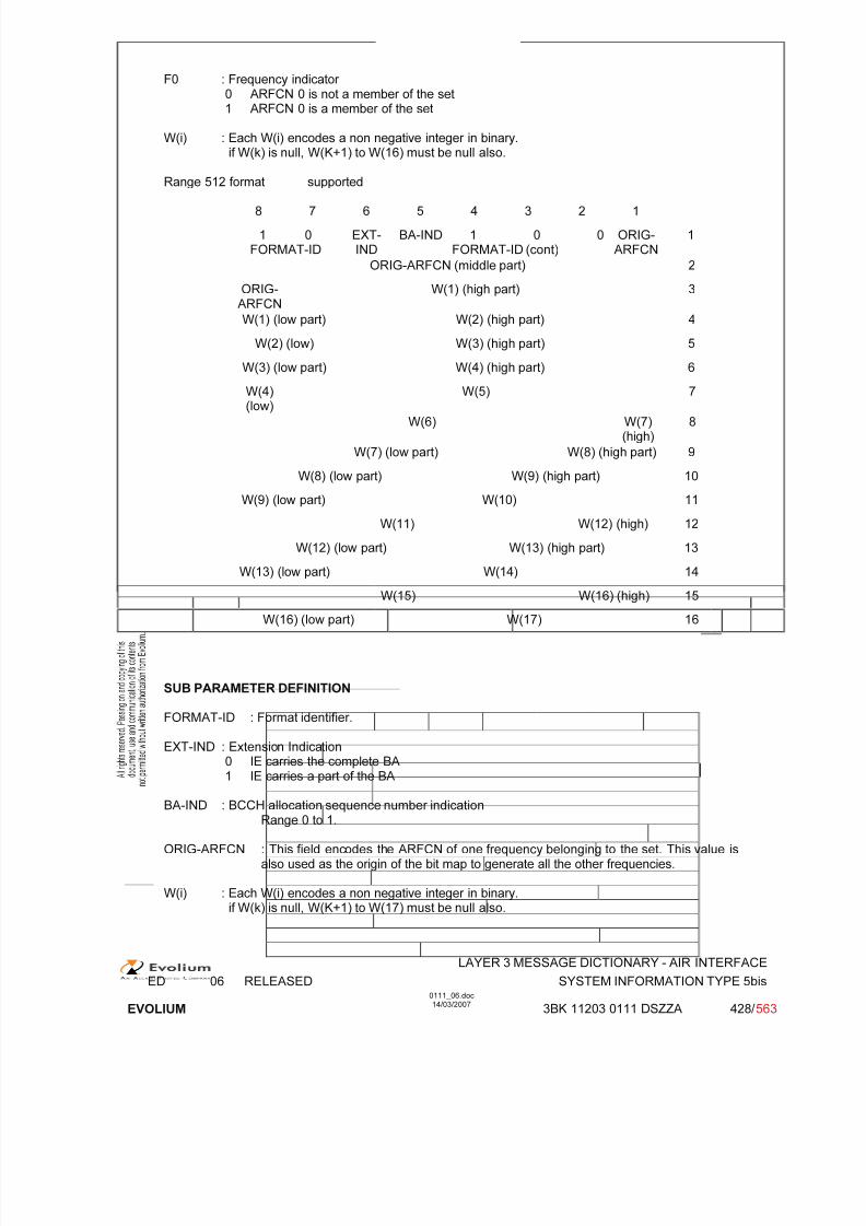
7/11/2019 1. Layer3 Air Interface Messages 0111_06
http://slidepdf.com/reader/full/1-layer3-air-interface-messages-011106 428/562
LAYER 3 MESSAGE DICTIONARY - AIR INTERFACE
ED 06 RELEASED SYSTEM INFORMATION TYPE 5bis
EVOLIUM
0111_06.doc14/03/2007
3BK 11203 0111 DSZZA 428/ 563
F0 : Frequency indicator 0 ARFCN 0 is not a member of the set1 ARFCN 0 is a member of the set
W(i) : Each W(i) encodes a non negative integer in binary.if W(k) is null, W(K+1) to W(16) must be null also.
Range 512 format supported
8 7 6 5 4 3 2 1
1 0FORMAT-ID
EXT-IND
BA-IND 1 0 0FORMAT-ID (cont)
ORIG-ARFCN
1
ORIG-ARFCN (middle part) 2
ORIG-ARFCN
W(1) (high part) 3
W(1) (low part) W(2) (high part) 4
W(2) (low) W(3) (high part) 5
W(3) (low part) W(4) (high part) 6
W(4)(low)
W(5) 7
W(6) W(7)(high)
8
W(7) (low part) W(8) (high part) 9
W(8) (low part) W(9) (high part) 10
W(9) (low part) W(10) 11
W(11) W(12) (high) 12
W(12) (low part) W(13) (high part) 13
W(13) (low part) W(14) 14
W(15) W(16) (high) 15
W(16) (low part) W(17) 16
SUB PARAMETER DEFINITION
FORMAT-ID : Format identifier.
EXT-IND : Extension Indication0 IE carries the complete BA1 IE carries a part of the BA
BA-IND : BCCH allocation sequence number indicationRange 0 to 1.
ORIG-ARFCN : This field encodes the ARFCN of one frequency belonging to the set. This value isalso used as the origin of the bit map to generate all the other frequencies.
W(i) : Each W(i) encodes a non negative integer in binary.if W(k) is null, W(K+1) to W(17) must be null also.
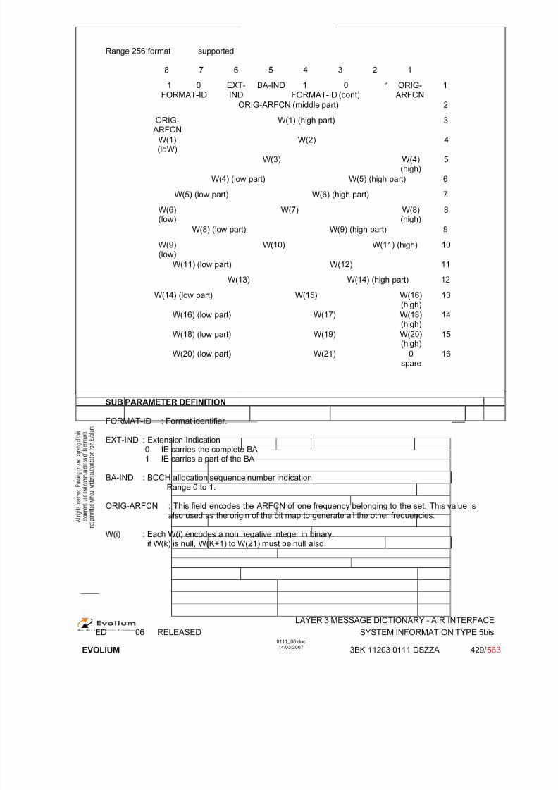
7/11/2019 1. Layer3 Air Interface Messages 0111_06
http://slidepdf.com/reader/full/1-layer3-air-interface-messages-011106 429/562
LAYER 3 MESSAGE DICTIONARY - AIR INTERFACE
ED 06 RELEASED SYSTEM INFORMATION TYPE 5bis
EVOLIUM
0111_06.doc14/03/2007
3BK 11203 0111 DSZZA 429/ 563
Range 256 format supported
8 7 6 5 4 3 2 1
1 0FORMAT-ID
EXT-IND
BA-IND 1 0 1FORMAT-ID (cont)
ORIG-ARFCN
1
ORIG-ARFCN (middle part) 2
ORIG-ARFCN
W(1) (high part) 3
W(1)(loW)
W(2) 4
W(3) W(4)(high)
5
W(4) (low part) W(5) (high part) 6
W(5) (low part) W(6) (high part) 7
W(6)(low)
W(7) W(8)(high)
8
W(8) (low part) W(9) (high part) 9
W(9)(low)
W(10) W(11) (high) 10
W(11) (low part) W(12) 11
W(13) W(14) (high part) 12
W(14) (low part) W(15) W(16)(high)
13
W(16) (low part) W(17) W(18)(high)
14
W(18) (low part) W(19) W(20)(high)
15
W(20) (low part) W(21) 0
spare
16
SUB PARAMETER DEFINITION
FORMAT-ID : Format identifier.
EXT-IND : Extension Indication0 IE carries the complete BA1 IE carries a part of the BA
BA-IND : BCCH allocation sequence number indication
Range 0 to 1.
ORIG-ARFCN : This field encodes the ARFCN of one frequency belonging to the set. This value isalso used as the origin of the bit map to generate all the other frequencies.
W(i) : Each W(i) encodes a non negative integer in binary.if W(k) is null, W(K+1) to W(21) must be null also.
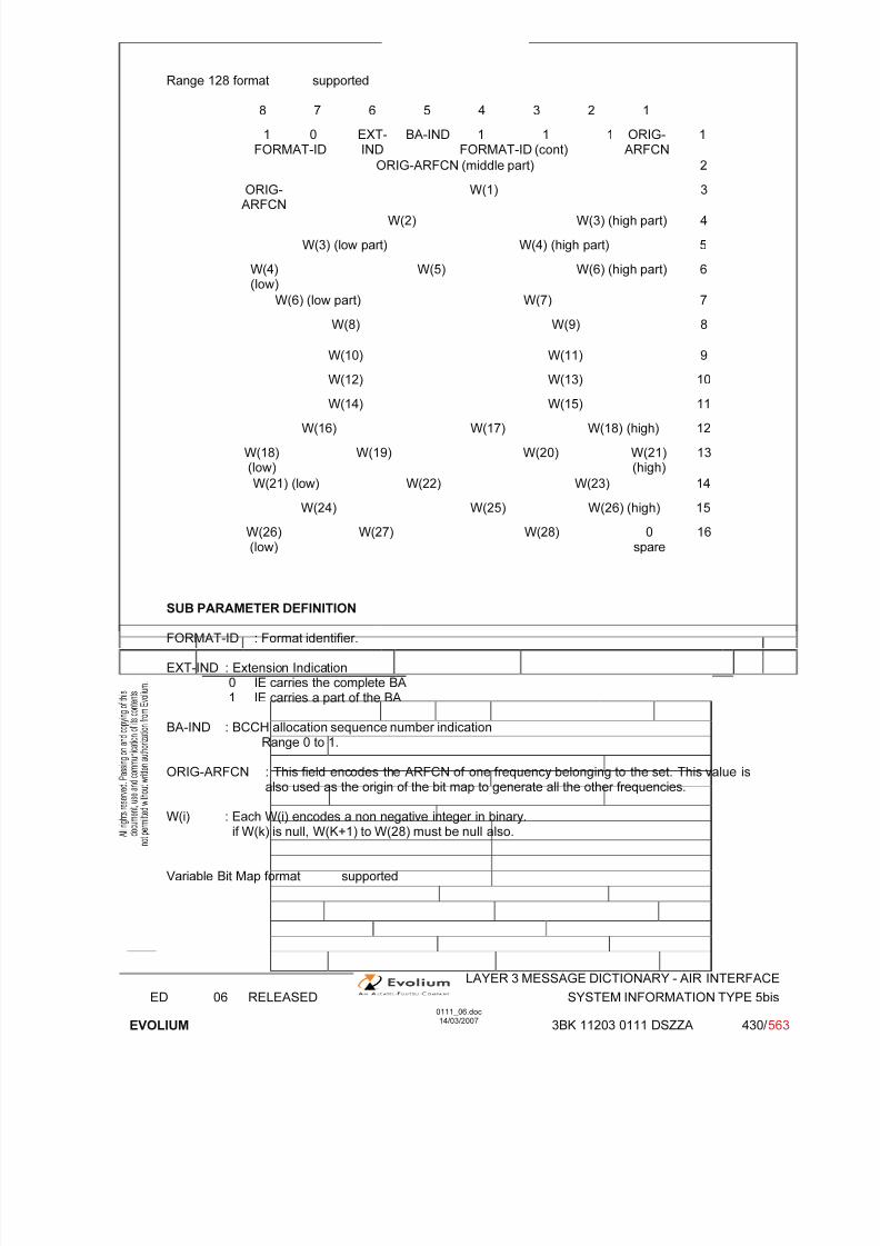
7/11/2019 1. Layer3 Air Interface Messages 0111_06
http://slidepdf.com/reader/full/1-layer3-air-interface-messages-011106 430/562
LAYER 3 MESSAGE DICTIONARY - AIR INTERFACE
ED 06 RELEASED SYSTEM INFORMATION TYPE 5bis
EVOLIUM
0111_06.doc14/03/2007
3BK 11203 0111 DSZZA 430/ 563
Range 128 format supported
8 7 6 5 4 3 2 1
1 0FORMAT-ID
EXT-IND
BA-IND 1 1 1FORMAT-ID (cont)
ORIG-ARFCN
1
ORIG-ARFCN (middle part) 2
ORIG-ARFCN
W(1) 3
W(2) W(3) (high part) 4
W(3) (low part) W(4) (high part) 5
W(4)(low)
W(5) W(6) (high part) 6
W(6) (low part) W(7) 7
W(8) W(9) 8
W(10) W(11) 9
W(12) W(13) 10
W(14) W(15) 11
W(16) W(17) W(18) (high) 12
W(18)(low)
W(19) W(20) W(21)(high)
13
W(21) (low) W(22) W(23) 14
W(24) W(25) W(26) (high) 15
W(26)(low)
W(27) W(28) 0spare
16
SUB PARAMETER DEFINITION
FORMAT-ID : Format identifier.
EXT-IND : Extension Indication0 IE carries the complete BA1 IE carries a part of the BA
BA-IND : BCCH allocation sequence number indicationRange 0 to 1.
ORIG-ARFCN : This field encodes the ARFCN of one frequency belonging to the set. This value isalso used as the origin of the bit map to generate all the other frequencies.
W(i) : Each W(i) encodes a non negative integer in binary.if W(k) is null, W(K+1) to W(28) must be null also.
Variable Bit Map format supported
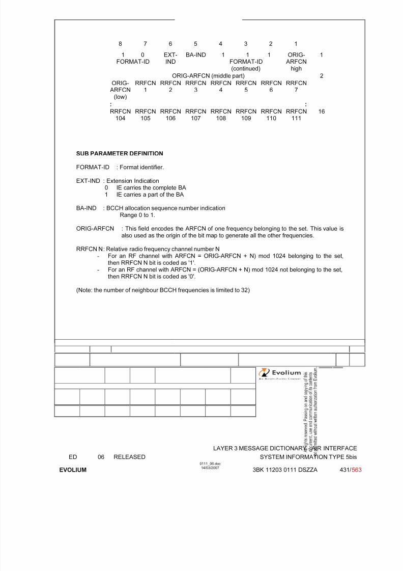
7/11/2019 1. Layer3 Air Interface Messages 0111_06
http://slidepdf.com/reader/full/1-layer3-air-interface-messages-011106 431/562
LAYER 3 MESSAGE DICTIONARY - AIR INTERFACE
ED 06 RELEASED SYSTEM INFORMATION TYPE 5bis
EVOLIUM
0111_06.doc14/03/2007
3BK 11203 0111 DSZZA 431/ 563
8 7 6 5 4 3 2 1
1 0FORMAT-ID
EXT-IND
BA-IND 1 1 1FORMAT-ID(continued)
ORIG-ARFCN
high
1
ORIG-ARFCN (middle part) 2
ORIG-
ARFCN(low)
RRFCN
1
RRFCN
2
RRFCN
3
RRFCN
4
RRFCN
5
RRFCN
6
RRFCN
7
: :
RRFCN104
RRFCN105
RRFCN106
RRFCN107
RRFCN108
RRFCN109
RRFCN110
RRFCN111
16
SUB PARAMETER DEFINITION
FORMAT-ID : Format identifier.
EXT-IND : Extension Indication0 IE carries the complete BA1 IE carries a part of the BA
BA-IND : BCCH allocation sequence number indicationRange 0 to 1.
ORIG-ARFCN : This field encodes the ARFCN of one frequency belonging to the set. This value isalso used as the origin of the bit map to generate all the other frequencies.
RRFCN N : Relative radio frequency channel number N- For an RF channel with ARFCN = ORIG-ARFCN + N) mod 1024 belonging to the set,
then RRFCN N bit is coded as '1'.- For an RF channel with ARFCN = (ORIG-ARFCN + N) mod 1024 not belonging to the set,
then RRFCN N bit is coded as '0'.
(Note: the number of neighbour BCCH frequencies is limited to 32)
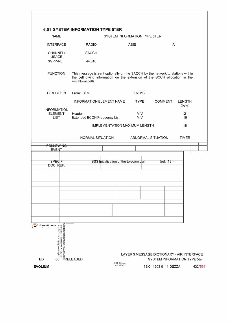
7/11/2019 1. Layer3 Air Interface Messages 0111_06
http://slidepdf.com/reader/full/1-layer3-air-interface-messages-011106 432/562
LAYER 3 MESSAGE DICTIONARY - AIR INTERFACE
ED 06 RELEASED SYSTEM INFORMATION TYPE 5ter
EVOLIUM
0111_06.doc14/03/2007
3BK 11203 0111 DSZZA 432/ 563
6.51 SYSTEM INFORMATION TYPE 5TER
NAME SYSTEM INFORMATION TYPE 5TER
INTERFACE RADIO ABIS A
CHANNEL/ USAGE
SACCH
3GPP-REF 44.018
FUNCTION This message is sent optionally on the SACCH by the network to stations withinthe cell giving information on the extension of the BCCH allocation in theneighbour cells.
DIRECTION From: BTS To: MS
INFORMATION ELEMENT NAME TYPE COMMENT LENGTH(byte)
INFORMATIONELEMENT
LISTHeader Extended BCCH Frequency List
M V M V
216
IMPLEMENTATION MAXIMUM LENGTH 18
NORMAL SITUATION ABNORMAL SITUATION TIMER
FOLLOWING
EVENT
SPECIFDOC. REF.
BSS Initialisation of the telecom part (ref. [19])

7/11/2019 1. Layer3 Air Interface Messages 0111_06
http://slidepdf.com/reader/full/1-layer3-air-interface-messages-011106 433/562
LAYER 3 MESSAGE DICTIONARY - AIR INTERFACE
ED 06 RELEASED SYSTEM INFORMATION TYPE 5ter
EVOLIUM
0111_06.doc14/03/2007
3BK 11203 0111 DSZZA 433/ 563
6.51.1 GENERAL DESCRIPTION
P-GSM
8 7 6 5 4 3 2 1
0 0 0 0 0 1 1 0
0 0 0 1 1 1 0 1
1FORMAT-ID Multiband
reportingBA-IND
BAARFCN
124
BAARFCN
123
BAARFCN
122
BAARFCN
121
BCCH BAARFCN
120
BAARFCN
119
BAARFCN
118
BAARFCN
117
BAARFCN
116
BAARFCN
115
BAARFCN
114
BAARFCN
113
Frequency ................
List BAARFCN
8
BAARFCN
7
BAARFCN
6
BAARFCN
5
BAARFCN
4
BAARFCN
3
BAARFCN
2
BAARFCN
1
E-GSM, DCS 1800, DCS1900, GSM850 and Biband
8 7 6 5 4 3 2 1
0 0 0 0 0 1 1 0
0 0 0 1 1 1 0 1
1FORMAT-ID Multibandreporting
BA-IND FORMAT-ID(continued)Note 1
ORIG-ARFCNhigh
BCCH ORIG-ARFCN (middle part)
FrequencyList
ORIG-ARFCN
(low)
RRFCN1
RRFCN2
RRFCN3
RRFCN4
RRFCN5
RRFCN6
RRFCN7
: :
RRFCN104
RRFCN105
RRFCN106
RRFCN107
RRFCN108
RRFCN109
RRFCN110
RRFCN111
Note 1: 0 x x: Range 1024 format;
1 0 0: Range 512 format;1 0 1: Range 256 format;1 1 0: Range 128 format;1 1 1: Variable bit map.

7/11/2019 1. Layer3 Air Interface Messages 0111_06
http://slidepdf.com/reader/full/1-layer3-air-interface-messages-011106 434/562
LAYER 3 MESSAGE DICTIONARY - AIR INTERFACE
ED 06 RELEASED SYSTEM INFORMATION TYPE 5ter
EVOLIUM
0111_06.doc14/03/2007
3BK 11203 0111 DSZZA 434/ 563
6.51.2 EXTENDED BCCH FREQUENCY LIST / NEIGHBOUR CELLS DESCRIPTION 2
TYPE: M
DEFINITIONTo provide the absolute radio frequency channel numbers of the extended BCCH carriers tobe monitored by the MS in the cell.
Used in this case for handover purposes.
BIT DESCRIPTION
Bitmap 0 Format supported for P-GSM.
8 7 6 5 4 3 2 1
0FORMAT-ID Multiband
Reporting
BA-IND BAARFCN
124
BAARFCN
123
BAARFCN
122
BAARFCN
121
1
BAARFCN
120
BAARFCN
119
BAARFCN
118
BAARFCN
117
BAARFCN
116
BAARFCN
115
BAARFCN
114
BAARFCN
113
2
................
BAARFCN
008
BAARFCN
007
BAARFCN
006
BAARFCN
005
BAARFCN
004
BAARFCN
003
BAARFCN
002
BAARFCN
001
16
SUB PARAMETER DEFINITION
FORMAT-ID Format identifier Multiband reporting Binary coded minimum number of cells of each supported band to be included
in MEASUREMENT REPORT message (if available). Range 0 to 3, set byO&M.
BA-IND BCCH allocation sequence number indicationRange 0 to 1
BA ARFCN N BCCH Allocation Absolute RF Channel Number Nif ARFCN = N belongs to the BCCH allocation,BA ARFCN N bit is coded with "1", N = 1,2 ...124if not, BA ARFCN N bit is coded with "0", N=1,2 ...124
(Note: the number of neighbour BCCH frequencies is limited to 32)

7/11/2019 1. Layer3 Air Interface Messages 0111_06
http://slidepdf.com/reader/full/1-layer3-air-interface-messages-011106 435/562
LAYER 3 MESSAGE DICTIONARY - AIR INTERFACE
ED 06 RELEASED SYSTEM INFORMATION TYPE 5ter
EVOLIUM
0111_06.doc14/03/2007
3BK 11203 0111 DSZZA 435/ 563
Range 1024 format supported
8 7 6 5 4 3 2 1
1FORMAT-ID
MultibandReporting
BA-IND 0
FORMAT-ID
F0 W(1) (high part) 1
W(1) (low part) 2
W(2) (high part) 3
W(2)(low)
W(3) (high part) 4
W(3) (low part) W(4) (high part) 5
W(4) (low part) W(5) (high part) 6
W(5) (low part) W(6) (high part) 7
W(6) (low part) W(7) (high part) 8
W(7) (low part) W(8) (high part) 9
W(8)(low)
W(9) 10
W(10) W(11)(high)
11
W(11) (low part) W(12) (high part) 12
W(12) (low part) W(13) (high part) 13
W(13) (low part) W(14) (high part) 14
W(14) (low part) W(15) (high part) 15
W(15) (low part) W(16) 16
SUB PARAMETER DEFINITION
FORMAT-ID Format identifier Multiband reporting Binary coded minimum number of cells of each supported band to be included
in MEASUREMENT REPORT message (if available). Range 0 to 3, set byO&M.
BA-IND BCCH allocation sequence number indicationRange 0 to 1.
F0 Frequency indicator 0 ARFCN 0 is not a member of the set1 ARFCN 0 is a member of the set
W(i) Each W(i) encodes a non negative integer in binary.if W(k) is null, W(K+1) to W(16) must be null also.

7/11/2019 1. Layer3 Air Interface Messages 0111_06
http://slidepdf.com/reader/full/1-layer3-air-interface-messages-011106 436/562
LAYER 3 MESSAGE DICTIONARY - AIR INTERFACE
ED 06 RELEASED SYSTEM INFORMATION TYPE 5ter
EVOLIUM
0111_06.doc14/03/2007
3BK 11203 0111 DSZZA 436/ 563
Range 512 format supported
8 7 6 5 4 3 2 1
1FORMAT-ID Multiband
Reporting
BA-IND 1 0 0FORMAT-ID(continued)
ORIG-ARFCN
1
ORIG-ARFCN (middle part) 2
ORIG-ARFCN
W(1) (high part) 3
W(1) (low part) W(2) (high part) 4
W(2) (low) W(3) (high part) 5
W(3) (low part) W(4) (high part) 6
W(4)(low)
W(5) 7
W(6) W(7)(high)
8
W(7) (low part) W(8) (high part) 9
W(8) (low part) W(9) (high part) 10
W(9) (low part) W(10) 11
W(11) W(12) (high) 12
W(12) (low part) W(13) (high part) 13
W(13) (low part) W(14) 14
W(15) W(16) (high) 15
W(16) (low part) W(17) 16
SUB PARAMETER DEFINITION
FORMAT-ID Format identifier Multiband reporting Binary coded minimum number of cells of each supported band to be included
in MEASUREMENT REPORT message (if available). Range 0 to 3, set byO&M.
BA-IND BCCH allocation sequence number indicationRange 0 to 1
ORIG-ARFCN This field encodes the ARFCN of one frequency belonging to the set. Thisvalue is also used as the origin of the bit map to generate all the other frequencies
W(i) Each W(i) encodes a non negative integer in binary.if W(k) is null, W(K+1) to W(17) must be null also.

7/11/2019 1. Layer3 Air Interface Messages 0111_06
http://slidepdf.com/reader/full/1-layer3-air-interface-messages-011106 437/562
LAYER 3 MESSAGE DICTIONARY - AIR INTERFACE
ED 06 RELEASED SYSTEM INFORMATION TYPE 5ter
EVOLIUM
0111_06.doc14/03/2007
3BK 11203 0111 DSZZA 437/ 563
Range 256 format supported
8 7 6 5 4 3 2 1
1FORMAT-ID Multiband
reporting
BA-IND 1 0 1FORMAT-ID(continued)
ORIG-ARFCN
1
ORIG-ARFCN (middle part) 2
ORIG-ARFCN
W(1) (high part) 3
W(1)(loW)
W(2) 4
W(3) W(4)(high)
5
W(4) (low part) W(5) (high part) 6
W(5) (low part) W(6) (high part) 7
W(6)
(low)
W(7) W(8)
(high)
8
W(8) (low part) W(9) (high part) 9
W(9)(low)
W(10) W(11) (high) 10
W(11) (low part) W(12) 11
W(13) W(14) (high part) 12
W(14) (low part) W(15) W(16)(high)
13
W(16) (low part) W(17) W(18)(high)
14
W(18) (low part) W(19) W(20)
(high)
15
W(20) (low part) W(21) 0spare
16
SUB PARAMETER DEFINITION
FORMAT-ID Format identifier Multiband reporting Binary coded minimum number of cells of each supported band to be included
in MEASUREMENT REPORT message (if available). Range 0 to 3, set byO&M.
BA-IND BCCH allocation sequence number indicationRange 0 to 1.
ORIG-ARFCN This field encodes the ARFCN of one frequency belonging to the set. Thisvalue is also used as the origin of the bit map to generate all the other frequencies.
W(i) Each W(i) encodes a non negative integer in binary.if W(k) is null, W(K+1) to W(21) must be null also.

7/11/2019 1. Layer3 Air Interface Messages 0111_06
http://slidepdf.com/reader/full/1-layer3-air-interface-messages-011106 438/562
LAYER 3 MESSAGE DICTIONARY - AIR INTERFACE
ED 06 RELEASED SYSTEM INFORMATION TYPE 5ter
EVOLIUM
0111_06.doc14/03/2007
3BK 11203 0111 DSZZA 438/ 563
Range 128 format supported
8 7 6 5 4 3 2 1
1FORMAT-ID Multiband
reporting
BA-IND 1 1 0FORMAT-ID(continued)
ORIG-ARFCN
1
ORIG-ARFCN (middle part) 2
ORIG-ARFCN
W(1) 3
W(2) W(3) (high part) 4
W(3) (low part) W(4) (high part) 5
W(4)(low)
W(5) W(6) (high part) 6
W(6) (low part) W(7) 7
W(8) W(9) 8
W(10) W(11) 9
W(12) W(13) 10
W(14) W(15) 11
W(16) W(17) W(18) (high) 12
W(18)(low)
W(19) W(20) W(21)(high)
13
W(21) (low) W(22) W(23) 14
W(24) W(25) W(26) (high) 15
W(26)
(low)
W(27) W(28) 0
spare
16
SUB PARAMETER DEFINITION
FORMAT-ID Format identifier Multiband reporting Binary coded minimum number of cells of each supported band to be included
in MEASUREMENT REPORT message (if available). Range 0 to 3, set byO&M.
BA-IND BCCH allocation sequence number indicationRange 0 to 1.
ORIG-ARFCN This field encodes the ARFCN of one frequency belonging to the set. Thisvalue is also used as the origin of the bit map to generate all the other frequencies.
W(i) Each W(i) encodes a non negative integer in binary.if W(k) is null, W(K+1) to W(28) must be null also.
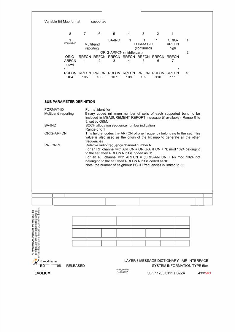
7/11/2019 1. Layer3 Air Interface Messages 0111_06
http://slidepdf.com/reader/full/1-layer3-air-interface-messages-011106 439/562
LAYER 3 MESSAGE DICTIONARY - AIR INTERFACE
ED 06 RELEASED SYSTEM INFORMATION TYPE 5ter
EVOLIUM
0111_06.doc14/03/2007
3BK 11203 0111 DSZZA 439/ 563
Variable Bit Map format supported
8 7 6 5 4 3 2 1
1FORMAT-ID Multiband
reporting
BA-IND 1 1 1FORMAT-ID(continued)
ORIG-ARFCN
high
1
ORIG-ARFCN (middle part) 2
ORIG-ARFCN
(low)
RRFCN1
RRFCN2
RRFCN3
RRFCN4
RRFCN5
RRFCN6
RRFCN7
: :
RRFCN104
RRFCN105
RRFCN106
RRFCN107
RRFCN108
RRFCN109
RRFCN110
RRFCN111
16
SUB PARAMETER DEFINITION
FORMAT-ID Format identifier Multiband reporting Binary coded minimum number of cells of each supported band to be
included in MEASUREMENT REPORT message (if available). Range 0 to3, set by O&M.
BA-IND BCCH allocation sequence number indicationRange 0 to 1
ORIG-ARFCN This field encodes the ARFCN of one frequency belonging to the set. Thisvalue is also used as the origin of the bit map to generate all the other frequencies
RRFCN N Relative radio frequency channel number NFor an RF channel with ARFCN = ORIG-ARFCN + N) mod 1024 belonging
to the set, then RRFCN N bit is coded as '1'.For an RF channel with ARFCN = (ORIG-ARFCN + N) mod 1024 notbelonging to the set, then RRFCN N bit is coded as '0'.Note: the number of neighbour BCCH frequencies is limited to 32

7/11/2019 1. Layer3 Air Interface Messages 0111_06
http://slidepdf.com/reader/full/1-layer3-air-interface-messages-011106 440/562
LAYER 3 MESSAGE DICTIONARY - AIR INTERFACE
ED 06 RELEASED SYSTEM INFORMATION TYPE 6
EVOLIUM
0111_06.doc14/03/2007
3BK 11203 0111 DSZZA 440/ 563
6.52 SYSTEM INFORMATION TYPE 6
NAME SYSTEM INFORMATION TYPE 6
INTERFACE RADIO ABIS A
CHANNEL/ USAGE SACCH
3GPP-REF 44.01844.018
FUNCTION This message is sent on the SACCH by the network to stations within the cellgiving information of location area and various other information about the cell.
DIRECTION From: BTS To: MS
INFORMATION ELEMENT NAME TYPE COMMENT LENGTH(byte)
INFORMATIONELEMENT
LISTHeader Cell IdentityLocation Area ID.Cell Options (SACCH)NCC permittedSI 6 Rest Octets
M V M V M V M V M V
225117
IMPLEMENTATION MAXIMUM LENGTH 18
NORMAL SITUATION ABNORMAL SITUATION TIMER
FOLLOWINGEVENT
SPECIFDOC. REF.
BSS Initialisation (ref. [19])

7/11/2019 1. Layer3 Air Interface Messages 0111_06
http://slidepdf.com/reader/full/1-layer3-air-interface-messages-011106 441/562
LAYER 3 MESSAGE DICTIONARY - AIR INTERFACE
ED 06 RELEASED SYSTEM INFORMATION TYPE 6
EVOLIUM
0111_06.doc14/03/2007
3BK 11203 0111 DSZZA 441/ 563
6.52.1 GENERAL DESCRIPTION
8 7 6 5 4 3 2 1
0 0 0 0 0 1 1 0
0 0 0 1 1 1 1 0
Cell Cell Identity value
Identity Cell Identity value (continued)
MCC Digit 2 MCC Digit 1
Location MNC Digit 3 (Note) MCC Digit 3
Area MNC Digit 2 MNC Digit 1
Identification LAC
LAC (continued)
Cell Option DTX PWRC DTX Radio-Link-Timeout
NCC Permitted NCC permitted
SI 6 Rest Octets See CSN.1 description in 6.52.6.
Note 3 digits MNC is supported. Note that in case where only two digits MNC is used, the field“MNC Digit 3” shall be filled in with “1111”.

7/11/2019 1. Layer3 Air Interface Messages 0111_06
http://slidepdf.com/reader/full/1-layer3-air-interface-messages-011106 442/562
LAYER 3 MESSAGE DICTIONARY - AIR INTERFACE
ED 06 RELEASED SYSTEM INFORMATION TYPE 6
EVOLIUM
0111_06.doc14/03/2007
3BK 11203 0111 DSZZA 442/ 563
6.52.2 CELL IDENTITY
TYPE: M
DEFINITIONIdentification of the cells within a location area.
BIT DESCRIPTION
8 7 6 5 4 3 2 1
Cell Identity value
CI value (continued)
Coding scheme depends on administration
SUB PARAMETER DEFINITION
CI value, Cell Identity value: See 3GPP TS 24.008.
PARAMETER ORIGIN - ACTION ON PARAMETER
6.52.3 LOCATION AREA IDENTIFICATION
TYPE: M
DEFINITIONTo provide unambiguous identification of Location Areas within the area covered by GSMsystem.
BIT DESCRIPTION
8 7 6 5 4 3 2 1
MCC Digit 2 MCC Digit 1
MNC Digit 3 (Note) MCC Digit 3MNC Digit 2 MNC Digit 1
LAC
LAC (continued)
Note 3 digits MNC is supported. Note that in case where only two digits MNC is used, the field“MNC Digit 3” shall be filled in with “1111”.
SUB PARAMETER DEFINITION

7/11/2019 1. Layer3 Air Interface Messages 0111_06
http://slidepdf.com/reader/full/1-layer3-air-interface-messages-011106 443/562
LAYER 3 MESSAGE DICTIONARY - AIR INTERFACE
ED 06 RELEASED SYSTEM INFORMATION TYPE 6
EVOLIUM
0111_06.doc14/03/2007
3BK 11203 0111 DSZZA 443/ 563
MCC Mobile Country Code (See CCITT. E.212)MNC Mobile Network Code (BCD)LAC Location Area Code See 3GPP TS 24.008 (Coding scheme chosen by adm)
PARAMETER ORIGIN - ACTION ON PARAMETERAll these parameters will be given to BSC during the Configuration.

7/11/2019 1. Layer3 Air Interface Messages 0111_06
http://slidepdf.com/reader/full/1-layer3-air-interface-messages-011106 444/562
LAYER 3 MESSAGE DICTIONARY - AIR INTERFACE
ED 06 RELEASED SYSTEM INFORMATION TYPE 6
EVOLIUM
0111_06.doc14/03/2007
3BK 11203 0111 DSZZA 444/ 563
6.52.4 CELL OPTIONS (SACCH)
TYPE: M
DEFINITIONTo provide a variety of information about a cell.
BIT DESCRIPTION
8 7 6 5 4 3 2 1
DTX PWRC DTX Radio-Link-Timeout
SUB PARAMETER DEFINITION
PWRC: Power control indicator 0: MS shall include measurement on the BCCH carrier. PWRC is not set1: MS shall not include measurement on the BCCH carrier. PWRC is set
DTX: DTX indicator
000: MS may use uplink discontinuous transmission on a TCH/F,MS shall not use uplink discontinuous transmission on TCH/H.
001: MS shall use uplink discontinuous transmission on a TCH/F,MS shall not use uplink discontinuous transmission on TCH/H.
010: MS shall not use uplink discontinuous transmission on a TCH/F,MS shall not use uplink discontinuous transmission on TCH/H.
011: MS shall use uplink discontinuous transmission on a TCH/F,MS may use uplink discontinuous transmission on TCH/H.
100: MS may use uplink discontinuous transmission on a TCH/F,MS may use uplink discontinuous transmission on TCH/H.
101: MS shall use uplink discontinuous transmission on a TCH/F,MS shall use uplink discontinuous transmission on TCH/H.
110: MS shall not use uplink discontinuous transmission on a TCH/F,MS shall use uplink discontinuous transmission on TCH/H.
111: MS may use uplink discontinuous transmission on a TCH/F,MS shall use uplink discontinuous transmission on TCH/H.
Radio-Link-Timeout
0000: 4 SACCH blocks0001: 8 SACCH blocks0010: 12 SACCH blocks…
1110: 60 SACCH blocks1111: 64 SACCH blocks
See 3GPP TS 05.08.
PARAMETER ORIGIN - ACTION ON PARAMETER
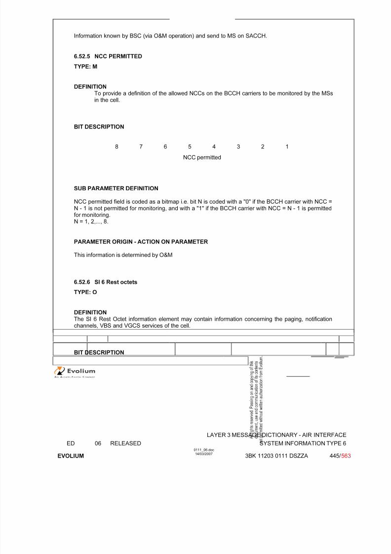
7/11/2019 1. Layer3 Air Interface Messages 0111_06
http://slidepdf.com/reader/full/1-layer3-air-interface-messages-011106 445/562
LAYER 3 MESSAGE DICTIONARY - AIR INTERFACE
ED 06 RELEASED SYSTEM INFORMATION TYPE 6
EVOLIUM
0111_06.doc14/03/2007
3BK 11203 0111 DSZZA 445/ 563
Information known by BSC (via O&M operation) and send to MS on SACCH.
6.52.5 NCC PERMITTED
TYPE: M
DEFINITIONTo provide a definition of the allowed NCCs on the BCCH carriers to be monitored by the MSsin the cell.
BIT DESCRIPTION
8 7 6 5 4 3 2 1
NCC permitted
SUB PARAMETER DEFINITION
NCC permitted field is coded as a bitmap i.e. bit N is coded with a "0" if the BCCH carrier with NCC =N - 1 is not permitted for monitoring, and with a "1" if the BCCH carrier with NCC = N - 1 is permittedfor monitoring.N = 1, 2,..., 8.
PARAMETER ORIGIN - ACTION ON PARAMETER
This information is determined by O&M
6.52.6 SI 6 Rest octets
TYPE: O
DEFINITIONThe SI 6 Rest Octet information element may contain information concerning the paging, notificationchannels, VBS and VGCS services of the cell.
BIT DESCRIPTION

7/11/2019 1. Layer3 Air Interface Messages 0111_06
http://slidepdf.com/reader/full/1-layer3-air-interface-messages-011106 446/562
LAYER 3 MESSAGE DICTIONARY - AIR INTERFACE
ED 06 RELEASED SYSTEM INFORMATION TYPE 6
EVOLIUM
0111_06.doc14/03/2007
3BK 11203 0111 DSZZA 446/ 563
SI6 rest octets> ::=
{L I H <PCH and NCH info>}
{L I H <VBS/VGCS options : bit(2)>}
{ < DTM_support : bit == L >I < DTM_support : bit == H >
< RAC : bit (8) >< MAX_LAPDm : bit (3) > }
< Band indicator >{ L | H < GPRS_MS_TXPWR_MAX_CCH : bit (5) > }
<implicit spare >;
PCH and NCH info> ::=<Paging channel restructuring><NLN(SACCH) : bit(2)>{0 I 1 <Call priority : bit (3)>}<NLN status(SACCH) : bit >;
paging channel restructuring> ::=1| -- paging channel is restructured0 -- paging channel is not restructured
<VBS/VGCS options> ::=<inband notifications><inband pagings>;
<inband notifications>::=0| -- the network does not provide notification on FACCH so that the mobile should
inspect the NCH for notifications1 -- the mobile shall be notified on incoming high priority VBS/VGCS calls through
NOTIFICATION/FACCH, the mobile need not to inspect the NCH
<inband pagings>::=0| -- the network does not provide paging information on FACCH so that the mobile
should inspect the PCH for pagings1 -- the mobile shall be notified on incoming high priority point-to-point calls
through NOTIFICATION/FACCH, the mobile need not to inspect the PCH
< Band indicator > ::=< BAND_INDICATOR : bit == L > -- ARFCN indicates 1800 band
| < BAND_INDICATOR : bit == H > ; -- ARFCN indicates 1900 band
SUB PARAMETER DEFINITION
PCH and NCH info
Presence indicator is set to L when the feature VGCS is disable else set to H.
This info element includes :- Paging channel restructuring that indicates if the paging channel is restructured.- Call priority that indicates the highest priority associated with VBS/VGCS calls in a cell.- NLN(Notification List Number) and NLN status :
They are managed on a per cell basis. There will be one Notification List ( of messages) per cell.
- When ever there is a modification in the Notification List due to a new voice group call (a newNotification message is added because a new VGCS call establishment) the NLN isincremented ( modulo 4). The NLN status is not touched.
- When there is change in the content of the Notification message or Notification List due to
existing voice group calls (there is a voice group call removed from the list or there is a
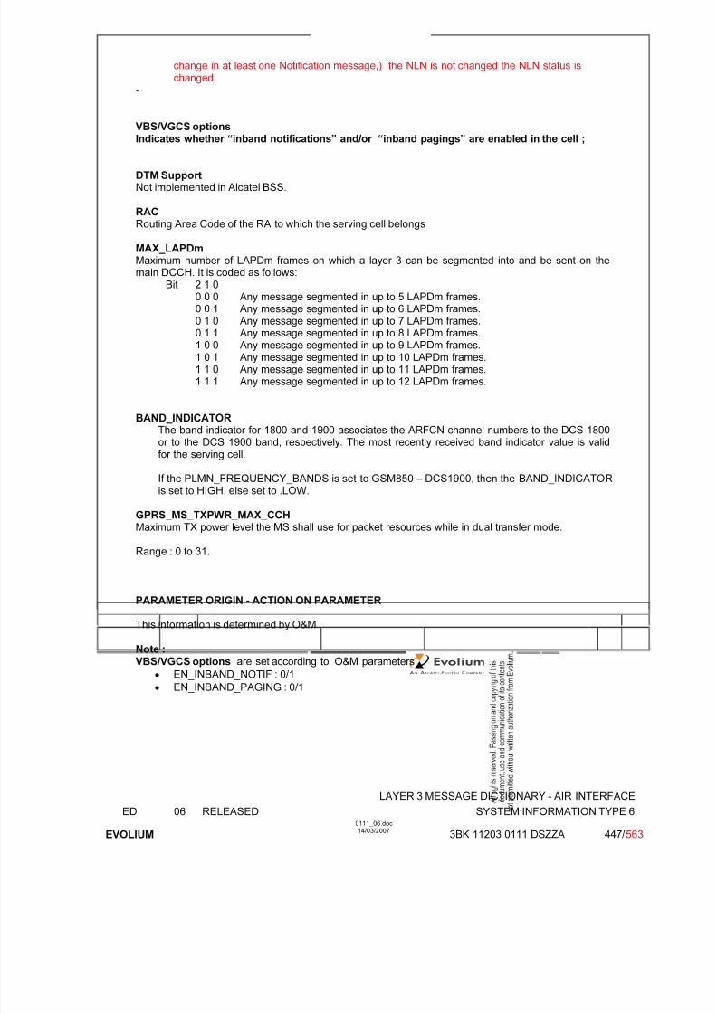
7/11/2019 1. Layer3 Air Interface Messages 0111_06
http://slidepdf.com/reader/full/1-layer3-air-interface-messages-011106 447/562
LAYER 3 MESSAGE DICTIONARY - AIR INTERFACE
ED 06 RELEASED SYSTEM INFORMATION TYPE 6
EVOLIUM
0111_06.doc14/03/2007
3BK 11203 0111 DSZZA 447/ 563
change in at least one Notification message,) the NLN is not changed the NLN status ischanged.
-
VBS/VGCS optionsIndicates whether “inband notifications” and/or “inband pagings” are enabled in the cell ;
DTM SupportNot implemented in Alcatel BSS.
RACRouting Area Code of the RA to which the serving cell belongs
MAX_LAPDmMaximum number of LAPDm frames on which a layer 3 can be segmented into and be sent on themain DCCH. It is coded as follows:
Bit 2 1 00 0 0 Any message segmented in up to 5 LAPDm frames.
0 0 1 Any message segmented in up to 6 LAPDm frames.0 1 0 Any message segmented in up to 7 LAPDm frames.0 1 1 Any message segmented in up to 8 LAPDm frames.1 0 0 Any message segmented in up to 9 LAPDm frames.1 0 1 Any message segmented in up to 10 LAPDm frames.1 1 0 Any message segmented in up to 11 LAPDm frames.1 1 1 Any message segmented in up to 12 LAPDm frames.
BAND_INDICATORThe band indicator for 1800 and 1900 associates the ARFCN channel numbers to the DCS 1800or to the DCS 1900 band, respectively. The most recently received band indicator value is validfor the serving cell.
If the PLMN_FREQUENCY_BANDS is set to GSM850 – DCS1900, then the BAND_INDICATORis set to HIGH, else set to .LOW.
GPRS_MS_TXPWR_MAX_CCHMaximum TX power level the MS shall use for packet resources while in dual transfer mode.
Range : 0 to 31.
PARAMETER ORIGIN - ACTION ON PARAMETER
This information is determined by O&M
Note :VBS/VGCS options are set according to O&M parameters
• EN_INBAND_NOTIF : 0/1
• EN_INBAND_PAGING : 0/1

7/11/2019 1. Layer3 Air Interface Messages 0111_06
http://slidepdf.com/reader/full/1-layer3-air-interface-messages-011106 448/562
LAYER 3 MESSAGE DICTIONARY - AIR INTERFACE
ED 06 RELEASED SYSTEM INFORMATION TYPE 7 AND 8
EVOLIUM
0111_06.doc14/03/2007
3BK 11203 0111 DSZZA 448/ 563
6.53 SYSTEM INFORMATION TYPE 7 and 8
NAME SYSTEM INFORMATION TYPE 7SYSTEM INFORMATION TYPE 8
INTERFACE RADIO ABIS A
CHANNEL/ USAGE BCCH Extended
3GPP-REF 44.01844.018
FUNCTIONThe SYSTEM INFORMATION TYPE 7 and 8 messages, related to SoLSA, canonly be sent on the BCCH Extended.
DIRECTION From: BTS To: MS
INFORMATION ELEMENT NAME TYPE COMMENT LENGTH(byte)
INFORMATION
ELEMENTLIST
L2 Pseudo LengthHeader SI 7 Rest Octets or SI 8 Rest Octets
M V M V M V
12
20 max.
IMPLEMENTATION MAXIMUM LENGTH 23
NORMAL SITUATION ABNORMAL SITUATION TIMER
FOLLOWINGEVENT
SPECIFDOC. REF.
System Information Management (ref. [24])

7/11/2019 1. Layer3 Air Interface Messages 0111_06
http://slidepdf.com/reader/full/1-layer3-air-interface-messages-011106 449/562
LAYER 3 MESSAGE DICTIONARY - AIR INTERFACE
ED 06 RELEASED SYSTEM INFORMATION TYPE 7 AND 8
EVOLIUM
0111_06.doc14/03/2007
3BK 11203 0111 DSZZA 449/ 563
6.53.1 GENERAL DESCRIPTION
SYSTEM INFORMATION TYPE 7:
8 7 6 5 4 3 2 1
L2 Pseudo Length L2 Pseudo Length Value=1 0 1
0 0 0 0 0 1 1 0
0 0 0 1 1 1 1 1
SI 7 Rest Octets See the table below for the detail
(20 bytes maximum)
SYSTEM INFORMATION TYPE 8:
8 7 6 5 4 3 2 1
L2 Pseudo Length L2 Pseudo Length Value=1 0 1
0 0 0 0 0 1 1 0
0 0 0 1 1 0 0 0
SI 8 Rest Octets See the table below for the detail
(20 bytes maximum)
SI 7 Rest Octets or SI 8 Rest Octets detail description:
Information elements Length (bit) Coding rules
1 Set to ‘H’ (LSA Parameters is used)PRIO_THR 3 See §6.53.2 for detail.
LSA_OFFSET 3 See §6.53.3 for detail.
1 Set to ‘0’ (Exclusive MCC/MNC is not used)
1 Set to ‘H’ (Cell Identity is used)
Cell Identity 16 See §6.53.4 for detail.
1 Set to ‘H’ (LSA ID information is used)
LSA ID information 134maximum
A list of LSA_IDs can be added until the 20 octetsof the SI 7 Rest Octets or SI 8 Rest Octets are

7/11/2019 1. Layer3 Air Interface Messages 0111_06
http://slidepdf.com/reader/full/1-layer3-air-interface-messages-011106 450/562
LAYER 3 MESSAGE DICTIONARY - AIR INTERFACE
ED 06 RELEASED SYSTEM INFORMATION TYPE 7 AND 8
EVOLIUM
0111_06.doc14/03/2007
3BK 11203 0111 DSZZA 450/ 563
full, see §6.53.5 for detail.
7/11/2019 1. Layer3 Air Interface Messages 0111_06
http://slidepdf.com/reader/full/1-layer3-air-interface-messages-011106 451/562
LAYER 3 MESSAGE DICTIONARY - AIR INTERFACE
ED 06 RELEASED SYSTEM INFORMATION TYPE 7 AND 8
EVOLIUM
0111_06.doc14/03/2007
3BK 11203 0111 DSZZA 451/ 563
6.53.2 PRIO_THR
TYPE: M
DEFINITION
The PRIO_THR field is a signal threshold used by the mobile station to determine whether prioritised
cell re-selection shall apply. The use and coding of this parameters is defined in 3GPP TS 05.08.
BIT DESCRIPTION
SUB PARAMETER DEFINITION
PARAMETER ORIGIN - ACTION ON PARAMETER
6.53.3 LSA_OFFSET
TYPE: M
DEFINITION
The LSA_OFFSET field applies an offset for LSA reselection between cells with same LSA priorities.The use and coding of this parameters is defined in 3GPP TS 05.08.
BIT DESCRIPTION
SUB PARAMETER DEFINITION
PARAMETER ORIGIN - ACTION ON PARAMETER
7/11/2019 1. Layer3 Air Interface Messages 0111_06
http://slidepdf.com/reader/full/1-layer3-air-interface-messages-011106 452/562
LAYER 3 MESSAGE DICTIONARY - AIR INTERFACE
ED 06 RELEASED SYSTEM INFORMATION TYPE 7 AND 8
EVOLIUM
0111_06.doc14/03/2007
3BK 11203 0111 DSZZA 452/ 563
6.53.4 CELL IDENTITY
TYPE: M
DEFINITION
The purpose of the Cell Identity is to identify a cell within a location area. The Cell Identity is defined in
3GPP TS 44.01844.018.
BIT DESCRIPTION
SUB PARAMETER DEFINITION
PARAMETER ORIGIN - ACTION ON PARAMETER

7/11/2019 1. Layer3 Air Interface Messages 0111_06
http://slidepdf.com/reader/full/1-layer3-air-interface-messages-011106 453/562
LAYER 3 MESSAGE DICTIONARY - AIR INTERFACE
ED 06 RELEASED SYSTEM INFORMATION TYPE 7 AND 8
EVOLIUM
0111_06.doc14/03/2007
3BK 11203 0111 DSZZA 453/ 563
6.53.5 LSA ID INFORMATION
TYPE: M
DEFINITIONThe purpose of the LSA_ID field is to identify a LSA (Localised Service Area).
BIT DESCRIPTION
<LSA ID information> ::= <LSA identity>{0 | 1 <LSA ID information>};
<LSA identity> ::= {0 <LSA_ID : bit (24)>|1 <ShortLSA_ID : bit (10)>};
Note: maximum of 5 long LSA_IDs (24 bits), or 11 ShortLSA_IDs (10 bits), or a mixture of the twocould be accomodated within SI 7 or SI 8 message.
SUB PARAMETER DEFINITION
PARAMETER ORIGIN - ACTION ON PARAMETER
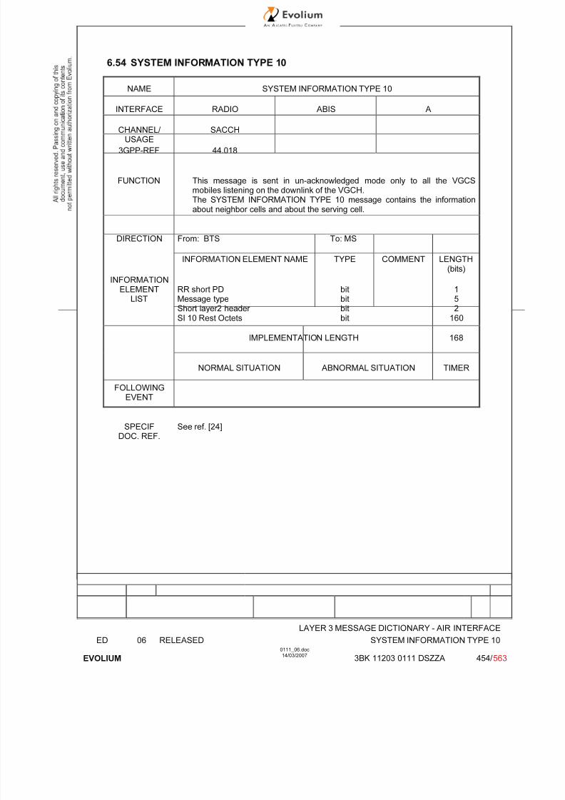
7/11/2019 1. Layer3 Air Interface Messages 0111_06
http://slidepdf.com/reader/full/1-layer3-air-interface-messages-011106 454/562
LAYER 3 MESSAGE DICTIONARY - AIR INTERFACE
ED 06 RELEASED SYSTEM INFORMATION TYPE 10
EVOLIUM
0111_06.doc14/03/2007
3BK 11203 0111 DSZZA 454/ 563
6.54 SYSTEM INFORMATION TYPE 10
NAME SYSTEM INFORMATION TYPE 10
INTERFACE RADIO ABIS A
CHANNEL/ USAGE
SACCH
3GPP-REF 44.018
FUNCTION This message is sent in un-acknowledged mode only to all the VGCSmobiles listening on the downlink of the VGCH.The SYSTEM INFORMATION TYPE 10 message contains the informationabout neighbor cells and about the serving cell.
DIRECTION From: BTS To: MS
INFORMATION ELEMENT NAME TYPE COMMENT LENGTH(bits)
INFORMATIONELEMENT
LISTRR short PDMessage typeShort layer2 header SI 10 Rest Octets
bitbitbitbit
152
160
IMPLEMENTATION LENGTH 168
NORMAL SITUATION ABNORMAL SITUATION TIMER
FOLLOWINGEVENT
SPECIFDOC. REF.
See ref. [24]
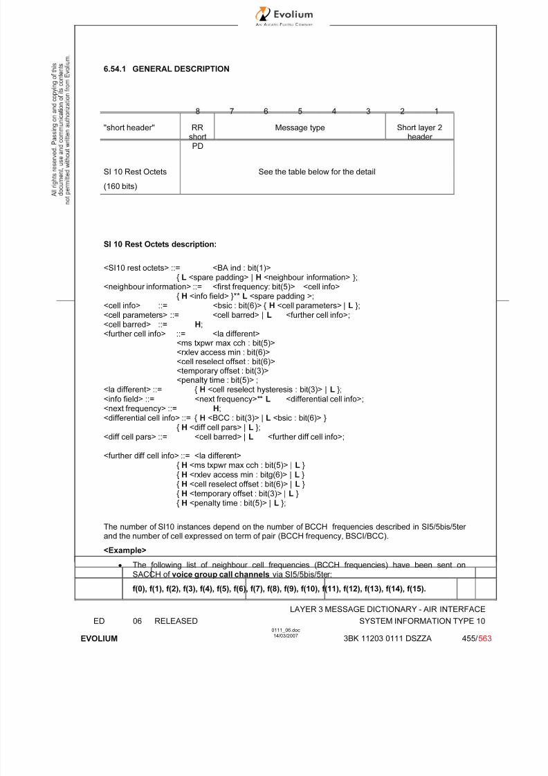
7/11/2019 1. Layer3 Air Interface Messages 0111_06
http://slidepdf.com/reader/full/1-layer3-air-interface-messages-011106 455/562
LAYER 3 MESSAGE DICTIONARY - AIR INTERFACE
ED 06 RELEASED SYSTEM INFORMATION TYPE 10
EVOLIUM
0111_06.doc14/03/2007
3BK 11203 0111 DSZZA 455/ 563
6.54.1 GENERAL DESCRIPTION
8 7 6 5 4 3 2 1
"short header" RRshortPD
Message type Short layer 2header
SI 10 Rest Octets See the table below for the detail
(160 bits)
SI 10 Rest Octets description:
<SI10 rest octets> ::= <BA ind : bit(1)>{ L <spare padding> | H <neighbour information> };
<neighbour information> ::= <first frequency: bit(5)> <cell info>{ H <info field> }** L <spare padding >;
<cell info> ::= <bsic : bit(6)> { H <cell parameters> | L };<cell parameters> ::= <cell barred> | L <further cell info>;<cell barred> ::= H;<further cell info> ::= <la different>
<ms txpwr max cch : bit(5)><rxlev access min : bit(6)><cell reselect offset : bit(6)><temporary offset : bit(3)><penalty time : bit(5)> ;
<la different> ::= { H <cell reselect hysteresis : bit(3)> | L };
<info field> ::= <next frequency>** L <differential cell info>;<next frequency> ::= H;<differential cell info> ::= { H <BCC : bit(3)> | L <bsic : bit(6)> }
{ H <diff cell pars> | L };<diff cell pars> ::= <cell barred> | L <further diff cell info>;
<further diff cell info> ::= <la different>{ H <ms txpwr max cch : bit(5)> | L }
{ H <rxlev access min : bitg(6)> | L }{ H <cell reselect offset : bit(6)> | L }{ H <temporary offset : bit(3)> | L }{ H <penalty time : bit(5)> | L };
The number of SI10 instances depend on the number of BCCH frequencies described in SI5/5bis/5ter and the number of cell expressed on term of pair (BCCH frequency, BSCI/BCC).
<Example>
• The following list of neighbour cell frequencies (BCCH frequencies) have been sent onSACCH of voice group call channels via SI5/5bis/5ter:
f(0), f(1), f(2), f(3), f(4), f(5), f(6), f(7), f(8), f(9), f(10), f(11), f(12), f(13), f(14), f(15).
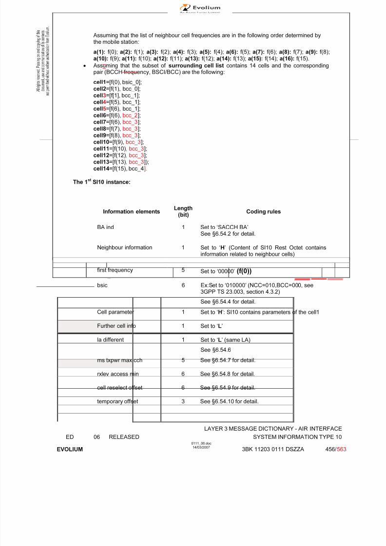
7/11/2019 1. Layer3 Air Interface Messages 0111_06
http://slidepdf.com/reader/full/1-layer3-air-interface-messages-011106 456/562
LAYER 3 MESSAGE DICTIONARY - AIR INTERFACE
ED 06 RELEASED SYSTEM INFORMATION TYPE 10
EVOLIUM
0111_06.doc14/03/2007
3BK 11203 0111 DSZZA 456/ 563
Assuming that the list of neighbour cell frequencies are in the following order determined bythe mobile station:
a(1): f(0); a(2): f(1); a(3): f(2); a(4): f(3); a(5): f(4); a(6): f(5); a(7): f(6); a(8): f(7); a(9): f(8); a(10): f(9); a(11): f(10); a(12): f(11); a(13): f(12); a(14): f(13); a(15): f(14); a(16): f(15).
• Assuming that the subset of surrounding cell list contains 14 cells and the correspondingpair (BCCH frequency, BSCI/BCC) are the following:
cell1=[f(0), bsic_0];cell2=[f(1), bcc_0];cell3=[f[1], bcc_1];cell4=[f(5), bcc_1];cell5=[f(6), bcc_1];cell6=[f(6), bcc_2];cell7=[f(6), bcc_3];
cell8=[f(7), bcc_3];cell9=[f(8), bcc_3];cell10=[f(9), bcc_3];cell11=[f(10), bcc_3];cell12=[f(12), bcc_3];cell13=[f(13), bcc_3]);
cell14=[f(15), bcc_4].
The 1st
SI10 instance:
Information elements Length
(bit)Coding rules
BA ind 1 Set to ‘SACCH BA’See §6.54.2 for detail.
Neighbour information 1 Set to ‘H’ (Content of SI10 Rest Octet contains
information related to neighbour cells)
first frequency 5 Set to ‘00000’ (f(0))
bsic 6 Ex:Set to ‘010000’ (NCC=010,BCC=000, see3GPP TS 23.003, section 4.3.2)
See §6.54.4 for detail.
Cell parameter 1 Set to ‘H’: SI10 contains parameters of the cell1
Further cell info 1 Set to ‘L’
la different 1 Set to ‘L’ (same LA)
See §6.54.6
ms txpwr max cch 5 See §6.54.7 for detail.
rxlev access min 6 See §6.54.8 for detail.
cell reselect offset 6 See §6.54.9 for detail.
temporary offset 3 See §6.54.10 for detail.

7/11/2019 1. Layer3 Air Interface Messages 0111_06
http://slidepdf.com/reader/full/1-layer3-air-interface-messages-011106 457/562
LAYER 3 MESSAGE DICTIONARY - AIR INTERFACE
ED 06 RELEASED SYSTEM INFORMATION TYPE 10
EVOLIUM
0111_06.doc14/03/2007
3BK 11203 0111 DSZZA 457/ 563
Information elements Length
(bit)Coding rules
penalty time 5 See §6.54.11 for detail.
1 H
(H <info field>) (1st occurrence of <info field>)
1 H
(H (<next frequency>: f(1))
1 L
(<next frequency>**L))
1 H
(H <BCC: bit(3)>)
BCC 3 ‘000’
1 L
({H <diff cell pars> | L }; cell2 has the some cellinfo as cell1)
1 H
(H <info field>) (2nd
occurrence of <info field>)
1 L (<next frequency>**L))
Note: f(1) is re-used with different BCC.
1 H (H <BCC: bit(3)>)
BCC 3 ‘001’
1 H
({H <diff cell pars> | L }; cell3 has some different
cell info than cell2)
1 L
(L <further diff cell info>)
la different 1 L
(<la different> ::= { H <cell reselecthysteresis : bit(3)> | L };): same LA)
1 L
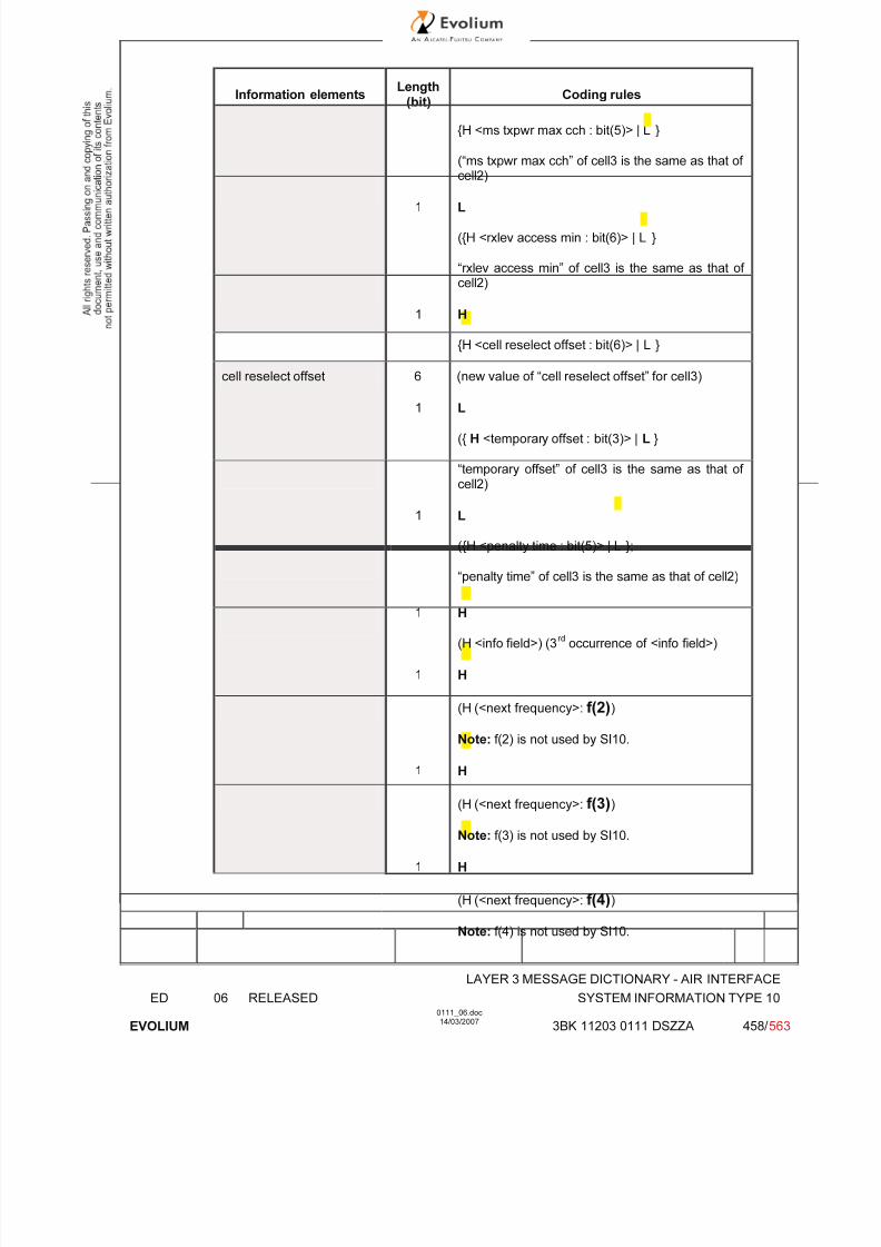
7/11/2019 1. Layer3 Air Interface Messages 0111_06
http://slidepdf.com/reader/full/1-layer3-air-interface-messages-011106 458/562
LAYER 3 MESSAGE DICTIONARY - AIR INTERFACE
ED 06 RELEASED SYSTEM INFORMATION TYPE 10
EVOLIUM
0111_06.doc14/03/2007
3BK 11203 0111 DSZZA 458/ 563
Information elements Length
(bit)Coding rules
{H <ms txpwr max cch : bit(5)> | L }
(“ms txpwr max cch” of cell3 is the same as that of cell2)
1 L
({H <rxlev access min : bit(6)> | L }
“rxlev access min” of cell3 is the same as that of cell2)
1 H
{H <cell reselect offset : bit(6)> | L }
cell reselect offset 6 (new value of “cell reselect offset” for cell3)
1 L
({ H <temporary offset : bit(3)> | L }
“temporary offset” of cell3 is the same as that of cell2)
1 L
({H <penalty time : bit(5)> | L };
“penalty time” of cell3 is the same as that of cell2)
1 H
(H <info field>) (3rd
occurrence of <info field>)
1 H
(H (<next frequency>: f(2))
Note: f(2) is not used by SI10.
1 H
(H (<next frequency>: f(3))
Note: f(3) is not used by SI10.
1 H
(H (<next frequency>: f(4))
Note: f(4) is not used by SI10.
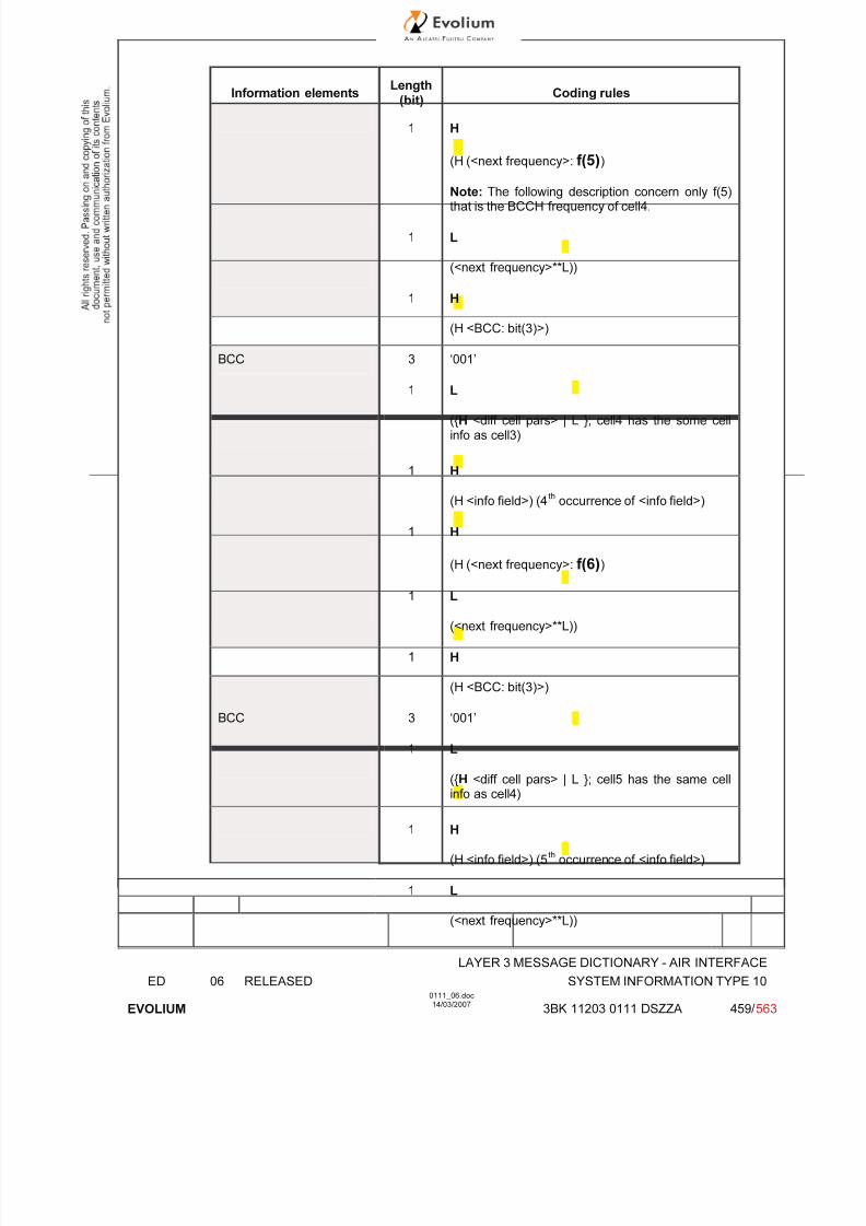
7/11/2019 1. Layer3 Air Interface Messages 0111_06
http://slidepdf.com/reader/full/1-layer3-air-interface-messages-011106 459/562
LAYER 3 MESSAGE DICTIONARY - AIR INTERFACE
ED 06 RELEASED SYSTEM INFORMATION TYPE 10
EVOLIUM
0111_06.doc14/03/2007
3BK 11203 0111 DSZZA 459/ 563
Information elements Length
(bit)Coding rules
1 H
(H (<next frequency>: f(5))
Note: The following description concern only f(5)that is the BCCH frequency of cell4.
1 L
(<next frequency>**L))
1 H
(H <BCC: bit(3)>)
BCC 3 ‘001’
1 L
({H <diff cell pars> | L }; cell4 has the some cellinfo as cell3)
1 H
(H <info field>) (4th
occurrence of <info field>)
1 H
(H (<next frequency>: f(6))
1 L
(<next frequency>**L))
1 H
(H <BCC: bit(3)>)
BCC 3 ‘001’
1 L
({H <diff cell pars> | L }; cell5 has the same cellinfo as cell4)
1 H
(H <info field>) (5th
occurrence of <info field>)
1 L
(<next frequency>**L))

7/11/2019 1. Layer3 Air Interface Messages 0111_06
http://slidepdf.com/reader/full/1-layer3-air-interface-messages-011106 460/562
LAYER 3 MESSAGE DICTIONARY - AIR INTERFACE
ED 06 RELEASED SYSTEM INFORMATION TYPE 10
EVOLIUM
0111_06.doc14/03/2007
3BK 11203 0111 DSZZA 460/ 563
Information elements Length
(bit)Coding rules
Note: f(6) is re-used with different BCC.
1 H
(H <BCC: bit(3)>)
BCC 3 ‘010’
1 H
({H <diff cell pars> | L }; cell6 has some differentcell info than cell5)
1 L
(L <further diff cell info>)
la different 1 L
(<la different> ::= { H <cell reselecthysteresis : bit(3)> | L };): same LA)
1 L
{H <ms txpwr max cch : bit(5)> | L }
(“ms txpwr max cch” of cell6 is the same as that of cell5)
1 L
({H <rxlev access min : bit(6)> | L }
“rxlev access min” of cell6 is the same as that of cell5)
1 L
{H <cell reselect offset : bit(6)> | L }
“cell reselect offset” of cell6 is the same as that of
cell5)
1 H
({ H <temporary offset : bit(3)> | L }
temporary offset 3 New value of “temporary offset” of cell6
1 L
({H <penalty time : bit(5)> | L };

7/11/2019 1. Layer3 Air Interface Messages 0111_06
http://slidepdf.com/reader/full/1-layer3-air-interface-messages-011106 461/562
LAYER 3 MESSAGE DICTIONARY - AIR INTERFACE
ED 06 RELEASED SYSTEM INFORMATION TYPE 10
EVOLIUM
0111_06.doc14/03/2007
3BK 11203 0111 DSZZA 461/ 563
Information elements Length
(bit)Coding rules
“penalty time” of cell6 is the same as that of cell5)
1 H
(H <info field>) (6th occurrence of <info field>)
1 L
(<next frequency>**L))
Note: f(6) is re-used with different BCC.
1 H
(H <BCC: bit(3)>)
BCC 3 ‘011’
1 L
({H <diff cell pars> | L }; cell7 has the same cellinfo as cell6)
1 H
(H <info field>) (7th
occurrence of <info field>)
1 H
(H (<next frequency>: f(7))
1 L
(<next frequency>**L))
1 H (H <BCC: bit(3)>)
BCC 3 ‘011’
1 H
({H <diff cell pars> | L }; cell8 has some differentcell info than cell7)
1 L
(L <further diff cell info>)
la different 1 L
(<la different> ::= { H <cell reselecthysteresis : bit(3)> | L };): same LA)

7/11/2019 1. Layer3 Air Interface Messages 0111_06
http://slidepdf.com/reader/full/1-layer3-air-interface-messages-011106 462/562
LAYER 3 MESSAGE DICTIONARY - AIR INTERFACE
ED 06 RELEASED SYSTEM INFORMATION TYPE 10
EVOLIUM
0111_06.doc14/03/2007
3BK 11203 0111 DSZZA 462/ 563
Information elements Length
(bit)Coding rules
1 L
{H <ms txpwr max cch : bit(5)> | L }
(“ms txpwr max cch” of cell8 is the same as that of cell7)
1 L
({H <rxlev access min : bit(6)> | L }
“rxlev access min” of cell8 is the same as that of cell7)
1 H
{H <cell reselect offset : bit(6)> | L }
cell reselect offset 6 (new value of “cell reselect offset” for cell11)
1 L
({ H <temporary offset : bit(3)> | L }
“temporary offset” of cell8 is the same as that of cell7)
1 L
({H <penalty time : bit(5)> | L };
“penalty time” of cell8 is the same as that of cell7)
1 H
(H <info field>) (8th
occurrence of <info field>)
1 H
(H (<next frequency>: f(8))
1 L
(<next frequency>**L))
1 H (H <BCC: bit(3)>)
BCC 3 ‘011’
1 H
({H <diff cell pars> | L }; cell9 has some differentcell info than cell8)
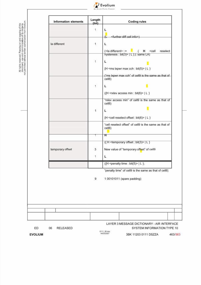
7/11/2019 1. Layer3 Air Interface Messages 0111_06
http://slidepdf.com/reader/full/1-layer3-air-interface-messages-011106 463/562
LAYER 3 MESSAGE DICTIONARY - AIR INTERFACE
ED 06 RELEASED SYSTEM INFORMATION TYPE 10
EVOLIUM
0111_06.doc14/03/2007
3BK 11203 0111 DSZZA 463/ 563
Information elements Length
(bit)Coding rules
1 L
(L <further diff cell info>)
la different 1 L
(<la different> ::= { H <cell reselecthysteresis : bit(3)> | L };): same LA)
1 L
{H <ms txpwr max cch : bit(5)> | L }
(“ms txpwr max cch” of cell9 is the same as that of cell8)
1 L
({H <rxlev access min : bit(6)> | L }
“rxlev access min” of cell9 is the same as that of cell8)
1 L
{H <cell reselect offset : bit(6)> | L }
“cell reselect offset” of cell9 is the same as that of cell8)
1 H
({ H <temporary offset : bit(3)> | L }
temporary offset 3 New value of “temporary offset” of cell9
1 L
({H <penalty time : bit(5)> | L };
“penalty time” of cell9 is the same as that of cell8)
9 1 00101011 (spare padding)

7/11/2019 1. Layer3 Air Interface Messages 0111_06
http://slidepdf.com/reader/full/1-layer3-air-interface-messages-011106 464/562
LAYER 3 MESSAGE DICTIONARY - AIR INTERFACE
ED 06 RELEASED SYSTEM INFORMATION TYPE 10
EVOLIUM
0111_06.doc14/03/2007
3BK 11203 0111 DSZZA 464/ 563
The 2nd
SI10 instance:
Information elements Length
(bit)Coding rules
BA ind 1 Set to ‘SACCH BA’See §6.54.2 for detail.
Neighbour information 1 Set to ‘H’ (Content of SI10 Rest Octet containsinformation related to neighbour cells)
first frequency 5 Set to ‘01001’ (f(9))
bsic 6 Ex:Set to ‘010011’ (NCC=010,BCC=011, see3GPP TS 23.003, section 4.3.2)
See §6.54.4 for detail.
Cell parameter 1 Set to ‘H’: SI10 contains parameters of the cell10(f(9))
Further cell info 1 Set to ‘L’
la different 1 Set to ‘L’ (same LA)
See §6.54.6
ms txpwr max cch 5 See §6.54.7 for detail.
rxlev access min 6 See §6.54.8 for detail.
cell reselect offset 6 See §6.54.9 for detail.
temporary offset 3 See §6.54.10 for detail.
penalty time 5 See §6.54.11 for detail.
1 H
(H <info field>) (1st
occurrence of <info field>)
1 H
(H (<next frequency>: f(10))
1 L
(<next frequency>**L))
1 H
(H <BCC: bit(3)>)
BCC 3 ‘011’

7/11/2019 1. Layer3 Air Interface Messages 0111_06
http://slidepdf.com/reader/full/1-layer3-air-interface-messages-011106 465/562
LAYER 3 MESSAGE DICTIONARY - AIR INTERFACE
ED 06 RELEASED SYSTEM INFORMATION TYPE 10
EVOLIUM
0111_06.doc14/03/2007
3BK 11203 0111 DSZZA 465/ 563
Information elements Length
(bit)Coding rules
1 L
({H <diff cell pars> | L }; cell11 (f(10)) has thesome cell info as cell10)
1 H
(H <info field>) (2nd
occurrence of <info field>)
1 H
(H (<next frequency>: f(11))
Note: f(11) is not used by SI10.
1 H
(H (<next frequency>: f(12))
1 L
(<next frequency>**L))
1 H
(H <BCC: bit(3)>)
BCC 3 ‘011’
1 L
({H <diff cell pars> | L }; cell12 [f(12)] has thesome cell info as cell11 [f(10)])
1 H
(H <info field>) (3rd
occurrence of <info field>)
1 H
(H (<next frequency>: f(13))
1 L
(<next frequency>**L))
1 H
(H <BCC: bit(3)>)
BCC 3 ‘011’
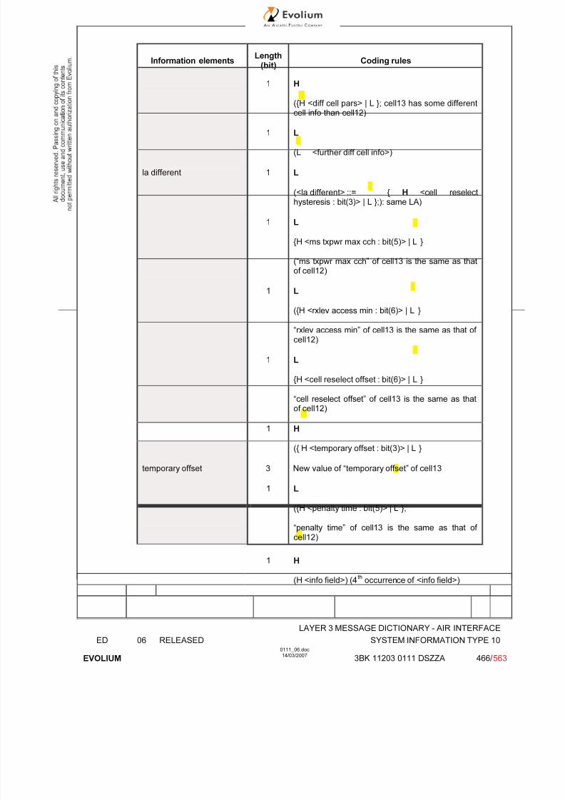
7/11/2019 1. Layer3 Air Interface Messages 0111_06
http://slidepdf.com/reader/full/1-layer3-air-interface-messages-011106 466/562
LAYER 3 MESSAGE DICTIONARY - AIR INTERFACE
ED 06 RELEASED SYSTEM INFORMATION TYPE 10
EVOLIUM
0111_06.doc14/03/2007
3BK 11203 0111 DSZZA 466/ 563
Information elements Length
(bit)Coding rules
1 H
({H <diff cell pars> | L }; cell13 has some differentcell info than cell12)
1 L
(L <further diff cell info>)
la different 1 L
(<la different> ::= { H <cell reselecthysteresis : bit(3)> | L };): same LA)
1 L
{H <ms txpwr max cch : bit(5)> | L }
(“ms txpwr max cch” of cell13 is the same as thatof cell12)
1 L
({H <rxlev access min : bit(6)> | L }
“rxlev access min” of cell13 is the same as that of cell12)
1 L
{H <cell reselect offset : bit(6)> | L }
“cell reselect offset” of cell13 is the same as thatof cell12)
1 H
({ H <temporary offset : bit(3)> | L }
temporary offset 3 New value of “temporary offset” of cell13
1 L
({H <penalty time : bit(5)> | L };
“penalty time” of cell13 is the same as that of cell12)
1 H
(H <info field>) (4th
occurrence of <info field>)

7/11/2019 1. Layer3 Air Interface Messages 0111_06
http://slidepdf.com/reader/full/1-layer3-air-interface-messages-011106 467/562
LAYER 3 MESSAGE DICTIONARY - AIR INTERFACE
ED 06 RELEASED SYSTEM INFORMATION TYPE 10
EVOLIUM
0111_06.doc14/03/2007
3BK 11203 0111 DSZZA 467/ 563
Information elements Length
(bit)Coding rules
1 H
(H (<next frequency>: f(14))
Note: f(14) is not used by SI10.
1 H
(H (<next frequency>: f(15))
1 L
(<next frequency>**L))
1 H
(H <BCC: bit(3)>)
BCC 3 ‘100’
1 L
({H <diff cell pars> | L }; cell14 has the some cellinfo as cell13)
75 011 00101011 00101011 00101011 0010101100101011 00101011 00101011 0010101100101011 (spare padding)
6.54.2 BA ind
BA-IND, BCCH allocation sequence number indication (octet 2). Range 0 to 1The BA-IND is needed to allow the network to discriminate measurements results related to different
BAs (e.g. BA(BCCH) and BA(SACCH)) sent to the MS.Information from the last received neighbour cell description in SYSTEM INFORMATION TYPE5/5bis/5ter is necessary for the mobile station to interpret <neighbour information>. If <BA ind> isdifferent from the last received BA IND value indicated in SYSTEM INFORMATION TYPE 5/5bis/5ter,<neighbour information> cannot be interpreted by the mobile station.
6.54.3 First frequency
It specifies a first frequency number n+1 where n is 0<= n <= 31.

7/11/2019 1. Layer3 Air Interface Messages 0111_06
http://slidepdf.com/reader/full/1-layer3-air-interface-messages-011106 468/562
LAYER 3 MESSAGE DICTIONARY - AIR INTERFACE
ED 06 RELEASED SYSTEM INFORMATION TYPE 10
EVOLIUM
0111_06.doc14/03/2007
3BK 11203 0111 DSZZA 468/ 563
6.54.4 Bsic
Each occurrence of bsic specifies a BSIC composed of a BCC(bit(3) and a NCC(bit(3)).Set by O& M
6.54.5 Cell barred
Indicates if cell is barred
6.54.6 La different
If "la different" contains a "cell reselect hysteresis : bit (3)", this means that the cell is to beconsidered by the mobile station to belong to a different location area and that for the cell, the cellreselect hysteresis specified in "cell reselect hysteresis : bit (3)" applies.If "la different" doesn't contain a "cell reselect hysteresis : bit (3)", this means that the cell is to beconsidered by the mobile station to belong to the same location area.
6.54.7 Ms txpwr max cch
Maximum transmission power an MS is allowed to use when accessing the cell until otherwisecommanded, broadcast on PBCCH for CS service establishment.Set by O&M
6.54.8 Rxlev access min
Minimum received level at the MS required for initial access to the cell.Set by O&M
6.54.9 Cell reselection offset
Permanent offset to C2 criterion.Set by O&M
6.54.10 Temporary offset
Offset applied to C2 criterion for the duration of PENALTY_TIMESet by O&M
6.54.11 Penalty time
Time during which MS shall apply TEMPORARY_OFFSET to C2 criterion.Set by O&M
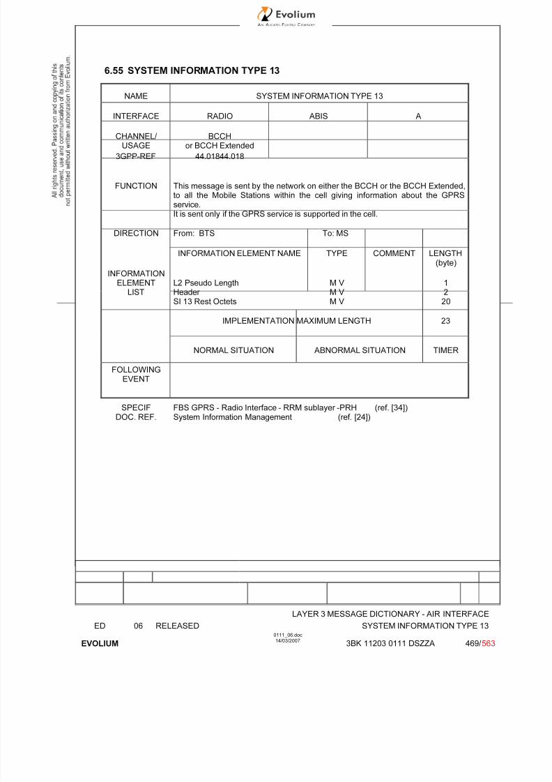
7/11/2019 1. Layer3 Air Interface Messages 0111_06
http://slidepdf.com/reader/full/1-layer3-air-interface-messages-011106 469/562
LAYER 3 MESSAGE DICTIONARY - AIR INTERFACE
ED 06 RELEASED SYSTEM INFORMATION TYPE 13
EVOLIUM
0111_06.doc14/03/2007
3BK 11203 0111 DSZZA 469/ 563
6.55 SYSTEM INFORMATION TYPE 13
NAME SYSTEM INFORMATION TYPE 13
INTERFACE RADIO ABIS A
CHANNEL/ USAGE
BCCHor BCCH Extended
3GPP-REF 44.01844.018
FUNCTION This message is sent by the network on either the BCCH or the BCCH Extended,to all the Mobile Stations within the cell giving information about the GPRSservice.It is sent only if the GPRS service is supported in the cell.
DIRECTION From: BTS To: MS
INFORMATION ELEMENT NAME TYPE COMMENT LENGTH(byte)
INFORMATIONELEMENT
LISTL2 Pseudo LengthHeader SI 13 Rest Octets
M V M V M V
1220
IMPLEMENTATION MAXIMUM LENGTH 23
NORMAL SITUATION ABNORMAL SITUATION TIMER
FOLLOWINGEVENT
SPECIFDOC. REF.
FBS GPRS - Radio Interface - RRM sublayer -PRH (ref. [34])System Information Management (ref. [24])

7/11/2019 1. Layer3 Air Interface Messages 0111_06
http://slidepdf.com/reader/full/1-layer3-air-interface-messages-011106 470/562
LAYER 3 MESSAGE DICTIONARY - AIR INTERFACE
ED 06 RELEASED SYSTEM INFORMATION TYPE 13
EVOLIUM
0111_06.doc14/03/2007
3BK 11203 0111 DSZZA 470/ 563
6.55.1 GENERAL DESCRIPTION
8 7 6 5 4 3 2 1
L2 Pseudo Length L2 Pseudo Length Value=0 0 1
0 0 0 0 0 1 1 00 0 0 0 0 0 0 0
SI 13 Rest Octets See the tables below for the detail
(20 bytes maximum)
SI 13 Rest Octets detail description (without PBCCH configured in the cell , in case of hoppingPDCH):
Information elements Length
(bit) Coding rules
1 Set to ‘H’ (Content of SI13 Rest Octet is notempty)
BCCH_CHANGE_MARK 3 See §6.55.2 for detail.
SI_CHANGE_FIELD 4 See §6.55.3 for detail.
1 Set to ‘1’.
SI13_CHANGE_MARK 2 See §6.55.4 for detail.
HSN 6 See §6.55.5 for detail.
1 Set to ‘0’ (RFL number list is not included).
1 Set to ‘0’ (MA_BITMAP is used).
MA_LENGTH 6 See §6.55.5 for detail.
MA_BITMAP val(MA_LENGTH) + 1
See §6.55.5 for detail.
1 Set to ‘0’ (PBCCH is not present in cell).
RAC 8 Routing Area Code, set to the ‘RA_CODE’ value.
SPGC_CCCH_SUP 1 Set to ‘0’ since SPLIT_PG_CYCLE on CCCH isnot supported.
PRIORITY_ACCESS_THR
3 Set to the ‘PRIORITY_ACCESS_THRESHOLD’value, see §6.55.6 for detail.
NETWORK_CONTROL_ ORDER
2 Set to the ‘NETWORK_CONTROL_ORDER’value, see §6.55.7 for detail.
NMO 2 Set to ‘NETWORK_OPERATION_MODE - 1’, see§6.55.8 for detail.
T3168 3 Set to the ‘T3168’ value, see §6.55.8 for detail.
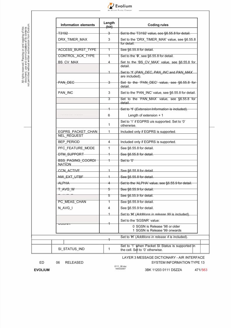
7/11/2019 1. Layer3 Air Interface Messages 0111_06
http://slidepdf.com/reader/full/1-layer3-air-interface-messages-011106 471/562
LAYER 3 MESSAGE DICTIONARY - AIR INTERFACE
ED 06 RELEASED SYSTEM INFORMATION TYPE 13
EVOLIUM
0111_06.doc14/03/2007
3BK 11203 0111 DSZZA 471/ 563
Information elements Length
(bit) Coding rules
T3192 3 Set to the ‘T3192’ value, see §6.55.8 for detail.
DRX_TIMER_MAX 3 Set to the ‘DRX_TIMER_MAX’ value, see §6.55.8for detail.
ACCESS_BURST_TYPE 1 See §6.55.8 for detail.
CONTROL_ACK_TYPE 1 Set to the ‘0’, see §6.55.8 for detail.
BS_CV_MAX 4 Set to the ‘BS_CV_MAX’ value, see §6.55.8 for detail.
1 Set to ‘1’ (PAN_DEC, PAN_INC and PAN_MAX are included).
PAN_DEC 3 Set to the ‘PAN_DEC’ value, see §6.55.8 for detail.
PAN_INC 3 Set to the ‘PAN_INC’ value, see §6.55.8 for detail.
PAN_MAX 3 Set to the ‘PAN_MAX’ value, see §6.55.8 for detail.
1 Set to ‘1’ (Extension Information is included).
Extension length 6 Length of extension + 1
1Set to ‘1’ if EGPRS uis supported. Set to ‘0’otherwise.
EGPRS_PACKET_CHANNEL_REQUEST
1 Included only if EGPRS is supported.
BEP_PERIOD 4 Included only if EGPRS is supported.
PFC_FEATURE_MODE 1 See §6.55.8 for detail.
DTM_SUPPORT 1 See §6.55.8 for detail.
BSS_PAGING_COORDINATION
1 Set to ‘0’
CCN_ACTIVE 1 See §6.55.8 for detail.
NW_EXT_UTBF 1 See §6.55.8 for detail.
ALPHA 4 Set to the ‘ALPHA’ value, see §6.55.9 for detail.
T_AVG_W 5 See §6.55.9 for detail.
T_AVG_T 5 See §6.55.9 for detail.
PC_MEAS_CHAN 1 See §6.55.9 for detail.
N_AVG_I 4 See §6.55.9 for detail.
1 Set to ‘H’ ( Additions in release 99 is included).
SGSNR 1Set to the ‘SGSNR’ value:
0 SGSN is Release '98 or older 1 SGSN is Release '99 onwards
1Set to ‘H’ ( Additions in release 4 is included).
SI_STATUS_IND 1Set to ‘1’ when Packet SI Status is supported inthe cell. Set to ‘0’ otherwise.

7/11/2019 1. Layer3 Air Interface Messages 0111_06
http://slidepdf.com/reader/full/1-layer3-air-interface-messages-011106 472/562
LAYER 3 MESSAGE DICTIONARY - AIR INTERFACE
ED 06 RELEASED SYSTEM INFORMATION TYPE 13
EVOLIUM
0111_06.doc14/03/2007
3BK 11203 0111 DSZZA 472/ 563
SI 13 Rest Octets detail description (with PBCCH configured in the cell, in case of non hoppingPDCHs):
Information elements Length
(bit) Coding rules
1 Set to ‘H’ (Content of SI13 Rest Octet is notempty)
BCCH_CHANGE_MARK 3 See §6.55.2 for detail.
SI_CHANGE_FIELD 4 See §6.55.3 for detail.
1 Set to ‘0’.
1 Set to ‘1’ (PBCCH is present in cell).
PSI1_REPEAT_PERIOD 4 See §6.55.10 for detail.
Pb 4 See §6.55.11 for detail.
TSC 3 See §6.55.11 for detail.
TN 3 See §6.55.11 for detail.
2 Set to ‘01’ ( ARFCN is used to describe thePBCCH frequency used, in case of non hoppingchannel)
ARFCN 10 See §6.55.11 for detail.
1 Set to ‘H’ ( Additions in release 99 is included).
SGSNR 1 Set to the ‘SGSNR’ value:0 SGSN is Release '98 or older 1 SGSN is Release '99 onwards
1Set to ‘H’ ( Additions in release 4 is included).
SI_STATUS_IND 1Set to ‘1’ when Packet SI Status is supported inthe cell. Set to ‘0’ otherwise.
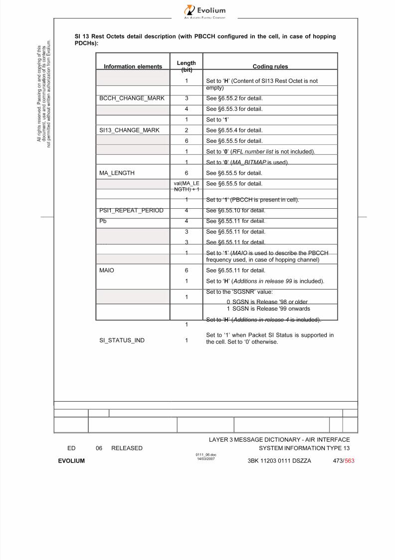
7/11/2019 1. Layer3 Air Interface Messages 0111_06
http://slidepdf.com/reader/full/1-layer3-air-interface-messages-011106 473/562
LAYER 3 MESSAGE DICTIONARY - AIR INTERFACE
ED 06 RELEASED SYSTEM INFORMATION TYPE 13
EVOLIUM
0111_06.doc14/03/2007
3BK 11203 0111 DSZZA 473/ 563
SI 13 Rest Octets detail description (with PBCCH configured in the cell, in case of hoppingPDCHs):
Information elements Length
(bit) Coding rules
1 Set to ‘H’ (Content of SI13 Rest Octet is not
empty)
BCCH_CHANGE_MARK 3 See §6.55.2 for detail.
SI_CHANGE_FIELD 4 See §6.55.3 for detail.
1 Set to ‘1’
SI13_CHANGE_MARK 2 See §6.55.4 for detail.
HSN 6 See §6.55.5 for detail.
1 Set to ‘0’ (RFL number list is not included).
1 Set to ‘0’ (MA_BITMAP is used).
MA_LENGTH 6 See §6.55.5 for detail.
MA_BITMAP val(MA_LENGTH) + 1
See §6.55.5 for detail.
1 Set to ‘1’ (PBCCH is present in cell).
PSI1_REPEAT_PERIOD 4 See §6.55.10 for detail.
Pb 4 See §6.55.11 for detail.
TSC 3 See §6.55.11 for detail.
TN 3 See §6.55.11 for detail.
1 Set to ‘1’ (MAIO is used to describe the PBCCH
frequency used, in case of hopping channel)
MAIO 6 See §6.55.11 for detail.
1 Set to ‘H’ ( Additions in release 99 is included).
SGSNR 1Set to the ‘SGSNR’ value:
0 SGSN is Release '98 or older 1 SGSN is Release '99 onwards
1Set to ‘H’ ( Additions in release 4 is included).
SI_STATUS_IND 1Set to ‘1’ when Packet SI Status is supported in
the cell. Set to ‘0’ otherwise.
7/11/2019 1. Layer3 Air Interface Messages 0111_06
http://slidepdf.com/reader/full/1-layer3-air-interface-messages-011106 474/562
LAYER 3 MESSAGE DICTIONARY - AIR INTERFACE
ED 06 RELEASED SYSTEM INFORMATION TYPE 13
EVOLIUM
0111_06.doc14/03/2007
3BK 11203 0111 DSZZA 474/ 563
6.55.2 BCCH_CHANGE_MARK
TYPE: M
DEFINITION
This field indicates the status of the information on BCCH. The value of this field may be changed
when information on BCCH is changed, see 3GPP TS 44.060.
BIT DESCRIPTION
SUB PARAMETER DEFINITION
PARAMETER ORIGIN - ACTION ON PARAMETER
The value of this field shall be increased by 1 each time the information content is changed on BCCH,but shall not be incremented when SI 13 only is modified.
6.55.3 SI_CHANGE_FIELD
TYPE: M
DEFINITION
SI_CHANGE_FIELD value indicates which SI among type 1, 2, 3, 4, 7, 8 (, 9) has changed at the lastBCCH_CHANGE_MARK indication. Range 0 to 15:
BIT DESCRIPTION
0 Update of unspecified SI message or SI messages: this is used in case of update of several different SI types (e.g. SI 16 & SI 17 modifications when LSA_IDs areconfigured in the cell)
1 Update of SI 1 message2 Update of SI 2, SI 2bis or SI 2ter message3 Update of SI 3, SI 4, SI 7 or SI 8 message4 Update of SI 9 message (not used, since SI 9 is not supported)5 Update of SI18 or SI20 message (not used, since SI 18 and SI 20 are not supported)6 Update of SI19 message(not used, since SI 19 is not supported)
All other values shall be interpreted as 'update of unknown SI message type'.
SUB PARAMETER DEFINITION
PARAMETER ORIGIN - ACTION ON PARAMETER
Upon changes of the contents of the RACH Control Parameters information element alone, it would besufficient that the SI_CHANGE_FIELD parameter indicates only one of the SI message containing theRACH Control Parameters (e.g. SI 1). But, in practice, the BSC only increments theBCCH_CHANGE_MARK value and does not update the SI_CHANGE_FIELD parameter. So the MS will get the last updated SI message(s) once more.
When there is no PBCCH configured in the cell, the BSC shall notify the MFS of anyBCCH_CHANGE_MARK modification with the new SI_CHANGE_FIELD value.
7/11/2019 1. Layer3 Air Interface Messages 0111_06
http://slidepdf.com/reader/full/1-layer3-air-interface-messages-011106 475/562
LAYER 3 MESSAGE DICTIONARY - AIR INTERFACE
ED 06 RELEASED SYSTEM INFORMATION TYPE 13
EVOLIUM
0111_06.doc14/03/2007
3BK 11203 0111 DSZZA 475/ 563
6.55.4 SI13_CHANGE_MARK
TYPE: O
DEFINITION
This field is the binary representation of the SI change mark identifying the GPRS Mobile Allocation
provided in SI13 messages.
BIT DESCRIPTION
Range: 0 to 3.
SUB PARAMETER DEFINITION
PARAMETER ORIGIN - ACTION ON PARAMETER
SI13_CHANGE_MARK is increased by 1 each time the GPRS Mobile Allocation or the Cell Allocationchanges (it is coded on 2 bits). The SI13_CHANGE_MARK is provided by the MFS through BSCGP
interface with cell radio configuration, see ref [36].

7/11/2019 1. Layer3 Air Interface Messages 0111_06
http://slidepdf.com/reader/full/1-layer3-air-interface-messages-011106 476/562
LAYER 3 MESSAGE DICTIONARY - AIR INTERFACE
ED 06 RELEASED SYSTEM INFORMATION TYPE 13
EVOLIUM
0111_06.doc14/03/2007
3BK 11203 0111 DSZZA 476/ 563
6.55.5 GPRS MOBILE ALLOCATION
TYPE: O
DEFINITION
This information element is the representation of the GPRS mobile allocation provided in SI13
message. It is identified by MA_NUMBER = 14 when referenced from a packet assignment message.The GPRS Mobile Allocation information element defines a set of radio frequency channels and ahopping sequence number (HSN), which may be allocated to a mobile station to define its channelconfiguration.
There are two alternative ways to encode the GPRS mobile allocation, using the MA_BITMAP or theARFCN index list. The MA_BITMAP is used by the Alcatel BSS.
BIT DESCRIPTION
< GPRS Mobile Allocation IE > ::=< HSN : bit (6) >{ 0 | 1 < RFL number list : < RFL number list struct > > }{ 0 < MA_LENGTH : bit (6) >
< MA_BITMAP : bit (val(MA_LENGTH) + 1) >
| 1 { 0 | 1 < ARFCN index list : < ARFCN index list struct > > } } ;
SUB PARAMETER DEFINITION
HSN (6 bit field)
This field is the binary representation of the hopping sequence number, Range: 0 to 63.
RFL number list (construction)
This construction is a list specifying the referenced set of reference frequency lists for thisinformation element. Note that the Alcatel BSS does not use this construction.
MA_BITMAP (variable length, 1 to 64 bit, field)
This field is a bitmap representing the radio frequency channels belonging to the GPRSmobile allocation. The number of bit positions in MA_BITMAP shall equal NF (NF: Number of Frequencies). The first bit position in MA_BITMAP corresponds to ARFCN_INDEX = NF-1, thelast position corresponds to ARFCN_INDEX = 0. Each bit position is coded:
0 the corresponding radio frequency channel does not belong to the GPRSmobile allocation;
1 the corresponding radio frequency channel belongs to the GPRS mobileallocation.
8 7 6 5 4 3 2 1
NF -1
: :
5 4 3 2 1 0
NF -2 NF -3 NF - 4 NF - 5 NF - 6 NF - 7 NF - 8
ARFCN index list (construction)
This construction is a list representing a set of radio frequency channels to be excluded fromthe definition of the GPRS mobile allocation. Note that the Alcatel BSS does not use thisconstruction.
PARAMETER ORIGIN - ACTION ON PARAMETER

7/11/2019 1. Layer3 Air Interface Messages 0111_06
http://slidepdf.com/reader/full/1-layer3-air-interface-messages-011106 477/562
LAYER 3 MESSAGE DICTIONARY - AIR INTERFACE
ED 06 RELEASED SYSTEM INFORMATION TYPE 13
EVOLIUM
0111_06.doc14/03/2007
3BK 11203 0111 DSZZA 477/ 563
6.55.6 PRIORITY_ACCESS_THR
TYPE: O
DEFINITION
This field is the binary representation of the parameter PRIORITY_ACCESS_THR.
BIT DESCRIPTION
0 0 0packet access is not allowed in the cell; 0 0 1spare, shall be interpreted as '000' (packet access not allowed);
0 1 0spare, shall be interpreted as '000' (packet access not allowed);0 1 1packet access is allowed for priority level 1;1 0 0packet access is allowed for priority level 1 to 2;1 0 1packet access is allowed for priority level 1 to 3;1 1 0packet access is allowed for priority level 1 to 4;1 1 1spare, shall be interpreted as '110' (packet access allowed).
SUB PARAMETER DEFINITION
PARAMETER ORIGIN - ACTION ON PARAMETER
6.55.7 NETWORK_CONTROL_ORDER
TYPE: O
DEFINITION
This field is the binary representation of the parameter NETWORK_CONTROL_ORDER.
BIT DESCRIPTION
0 0 NC0: MS controlled cell re-selection, no measurement reporting.0 1 NC1: MS controlled cell re-selection, MS sends measurement reports (not used).
1 0 NC2: Network controlled cell re-selection, MS sends measurement reports (not used).1 1 Reserved for future use, interpreted as NC0 by mobile station.
SUB PARAMETER DEFINITION
PARAMETER ORIGIN - ACTION ON PARAMETER
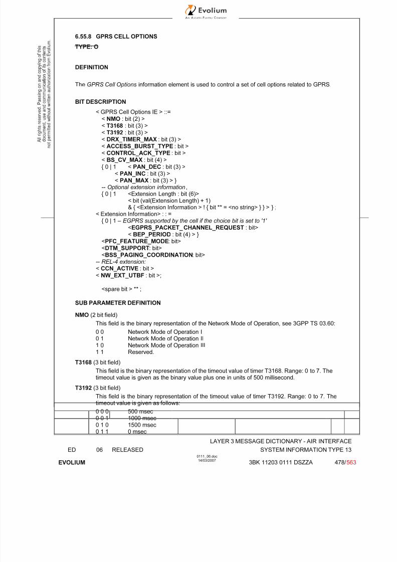
7/11/2019 1. Layer3 Air Interface Messages 0111_06
http://slidepdf.com/reader/full/1-layer3-air-interface-messages-011106 478/562
LAYER 3 MESSAGE DICTIONARY - AIR INTERFACE
ED 06 RELEASED SYSTEM INFORMATION TYPE 13
EVOLIUM
0111_06.doc14/03/2007
3BK 11203 0111 DSZZA 478/ 563
6.55.8 GPRS CELL OPTIONS
TYPE: O
DEFINITION
The GPRS Cell Options information element is used to control a set of cell options related to GPRS.
BIT DESCRIPTION
< GPRS Cell Options IE > ::=
< NMO : bit (2) >< T3168 : bit (3) >< T3192 : bit (3) >< DRX_TIMER_MAX : bit (3) >< ACCESS_BURST_TYPE : bit >< CONTROL_ACK_TYPE : bit >< BS_CV_MAX : bit (4) >
{ 0 | 1 < PAN_DEC : bit (3) >
< PAN_INC : bit (3) >< PAN_MAX : bit (3) > }
-- Optional extension information,{ 0 | 1 <Extension Length : bit (6)>
< bit (val(Extension Length) + 1)& { <Extension Information > ! { bit ** = <no string> } } > } ;
< Extension Information> : : ={ 0 | 1 – EGPRS supported by the cell if the choice bit is set to '1'
<EGPRS_PACKET_ CHANNEL_REQUEST : bit>< BEP_PERIOD : bit (4) > }
<PFC_FEATURE_MODE: bit><DTM_SUPPORT: bit><BSS_PAGING_COORDINATION: bit>
-- REL-4 extension: < CCN_ACTIVE : bit >
< NW_EXT_UTBF : bit >;
<spare bit > ** ;
SUB PARAMETER DEFINITION
NMO (2 bit field)
This field is the binary representation of the Network Mode of Operation, see 3GPP TS 03.60:
0 0 Network Mode of Operation I0 1 Network Mode of Operation II
1 0 Network Mode of Operation III1 1 Reserved.
T3168 (3 bit field)
This field is the binary representation of the timeout value of timer T3168. Range: 0 to 7. Thetimeout value is given as the binary value plus one in units of 500 millisecond.
T3192 (3 bit field)
This field is the binary representation of the timeout value of timer T3192. Range: 0 to 7. Thetimeout value is given as follows:
0 0 0 500 msec0 0 1 1000 msec0 1 0 1500 msec
0 1 1 0 msec

7/11/2019 1. Layer3 Air Interface Messages 0111_06
http://slidepdf.com/reader/full/1-layer3-air-interface-messages-011106 479/562
LAYER 3 MESSAGE DICTIONARY - AIR INTERFACE
ED 06 RELEASED SYSTEM INFORMATION TYPE 13
EVOLIUM
0111_06.doc14/03/2007
3BK 11203 0111 DSZZA 479/ 563
1 0 0 80 msec1 0 1 120 msec1 1 0 160 msec1 1 1 200 msec
DRX_TIMER_MAX (3 bit field)
This field is the binary representation of the parameter DRX_TIMER_MAX. Range: 0 to 7. Theparameter value is given as two taken to the power of the binary value minus one (2 (bv - 1) ) inunits of 1 second. The binary value zero indicates the parameter value zero (i.e, theparameter takes the values: 0, 1 s, 2 s, 4 s, .. 64 s.)
ACCESS_BURST_TYPE (1 bit field)
The ACCESS_BURST_TYPE field indicates if the 8 or 11 bit format shall be used in thePACKET CHANNEL REQUEST message, the PTCCH uplink block (3GPP TS 04.04) and inthe PACKET CONTROL ACKNOWLEDGMENT message when the format is four accessbursts. The field is coded as follows:
0 8-bit format shall be used1 11-bit format shall be used
CONTROL_ACK_TYPE (1 bit field)
This field is the binary representation of the default format of the PACKET CONTROLACKNOWLEDGMENT message:
0 default format is four access bursts1 default format is RLC/MAC control block. (not used)
BS_CV_MAX (4 bit field)
This field is the binary representation of the parameter BS_CV_MAX. Range: 0 to 15. Thevalue BS_CV_MAX=0 shall be interpreted as value BS_CV_MAX=1 for calculation of T3198,T3200 and N3104max values
PAN_DEC (3 bit field)
This field is the binary representation of the parameter PAN_DEC. If the field in not included,the default value 0 shall be used. Range: 0 to 7.
PAN_INC (3 bit field)
This field is the binary representation of the parameter PAN_INC. If the field in not included,the default value 0 shall be used. Range: 0 to 7.
PAN_MAX (3 bit field)
This field defines the maximum value allowed for counter N3102.0 0 0 maximum value allowed for counter N3102 is 40 0 1 maximum value allowed for counter N3102 is 8. . .1 1 1 maximum value allowed for counter N3102 is 32
If the PAN_MAX field in not included, the default value 0 (i.e. N3102 max = 4) shall be used.
Optional extension information:
EGPRS_PACKET_CHANNEL_REQUEST (1 bit field)
0 EGPRS capable MSs shall use EGPRS PACKET CHANNEL REQUESTmessage for uplink TBF establishment on the PRACH when there is a PBCCH inthe cell or on the RACH when there is no PBCCH in the cell.
1 EGPRS capable MSs shall use two phase packet access with PACKETCHANNEL REQUEST message on the PRACH for uplink TBF establishment when there is a PBCCH in the cell. EGPRS capable MSs shall use two phasepacket access with CHANNEL REQUEST message on the RACH when there isno PBCCH in the cell.

7/11/2019 1. Layer3 Air Interface Messages 0111_06
http://slidepdf.com/reader/full/1-layer3-air-interface-messages-011106 480/562
LAYER 3 MESSAGE DICTIONARY - AIR INTERFACE
ED 06 RELEASED SYSTEM INFORMATION TYPE 13
EVOLIUM
0111_06.doc14/03/2007
3BK 11203 0111 DSZZA 480/ 563
BEP_PERIOD (4 bit field)
This field contains the bit error probability (BEP) filter averaging period
PFC_FEATURE_MODE (1 bit field)
0 The network does not support packet flow context procedures.
1 The network supports packet flow context procedures.
DTM_SUPPORT (1 bit field)
This field indicates whether the cell supports DTM or not. It is coded as follows:
0 The cell does not support DTM procedures.
1 The cell supports DTM procedures. not used
BSS_PAGING_COORDINATION (1 bit field)
This field indicates the network support of CS paging co-ordination in packet transfer modeduring network mode of operation II and III. This field shall be ignored by the mobile stationduring network mode of operation I. It is coded as follows:
0 The cell does not support Circuit-Switched paging co-ordination
1 The cell supports Circuit-Switched paging co-ordination
CCN_ACTIVE (1 bit field)
This field indicates whether the cell supports Network Assisted Cell Change (NACC) or not. Itis coded as follows :
0 The cell does not support NACC procedures.
1 The cell supports NACC procedures.
NW_EXT_UTBF (1 bit field)
This field indicates whether the cell supports Uplink Extended TBF mode or not. It is coded asfollows :
0 The cell does not support Extended UL TBF mode procedures.
1 The cell supports Extended UL TBF mode procedures.
PARAMETER ORIGIN - ACTION ON PARAMETER
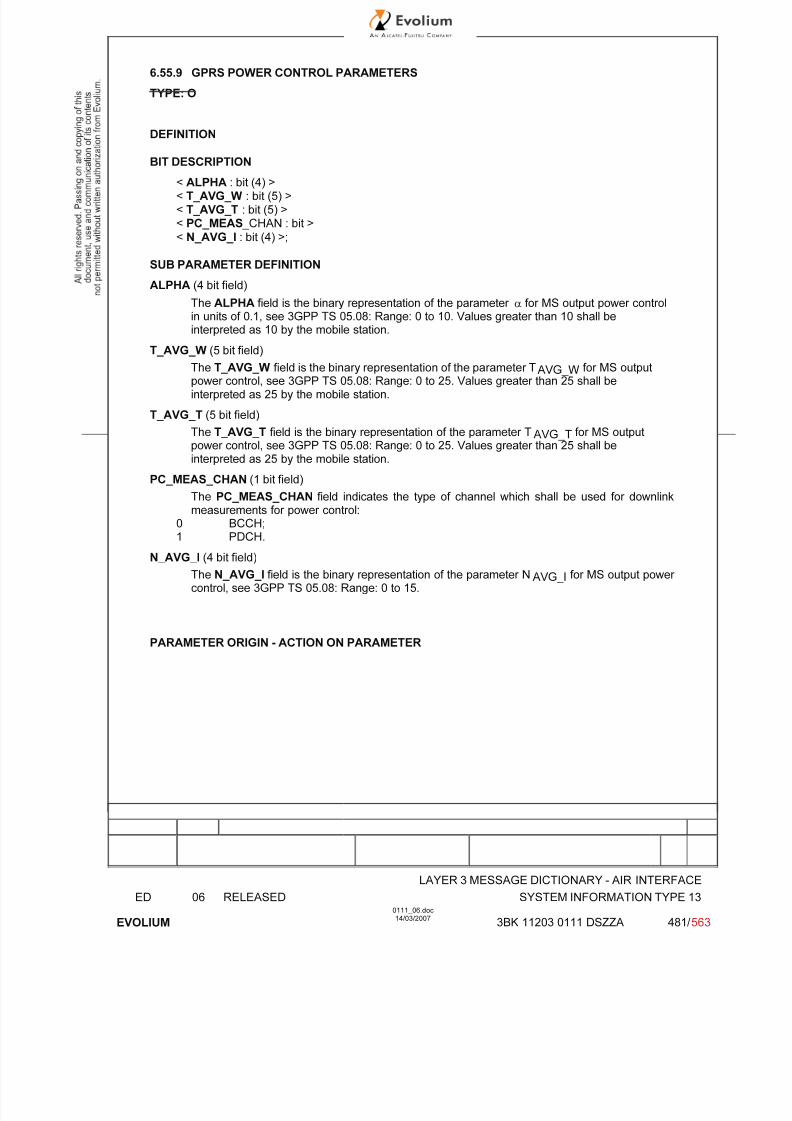
7/11/2019 1. Layer3 Air Interface Messages 0111_06
http://slidepdf.com/reader/full/1-layer3-air-interface-messages-011106 481/562
LAYER 3 MESSAGE DICTIONARY - AIR INTERFACE
ED 06 RELEASED SYSTEM INFORMATION TYPE 13
EVOLIUM
0111_06.doc14/03/2007
3BK 11203 0111 DSZZA 481/ 563
6.55.9 GPRS POWER CONTROL PARAMETERS
TYPE: O
DEFINITION
BIT DESCRIPTION
< ALPHA : bit (4) >< T_AVG_W : bit (5) >< T_AVG_T : bit (5) >< PC_MEAS _CHAN : bit >
< N_AVG_I : bit (4) >;
SUB PARAMETER DEFINITION
ALPHA (4 bit field)
The ALPHA field is the binary representation of the parameter α for MS output power controlin units of 0.1, see 3GPP TS 05.08: Range: 0 to 10. Values greater than 10 shall beinterpreted as 10 by the mobile station.
T_AVG_W (5 bit field)
The T_AVG_W field is the binary representation of the parameter TAVG_W for MS outputpower control, see 3GPP TS 05.08: Range: 0 to 25. Values greater than 25 shall beinterpreted as 25 by the mobile station.
T_AVG_T (5 bit field)
The T_AVG_T field is the binary representation of the parameter TAVG_T for MS outputpower control, see 3GPP TS 05.08: Range: 0 to 25. Values greater than 25 shall beinterpreted as 25 by the mobile station.
PC_MEAS_CHAN (1 bit field)
The PC_MEAS_CHAN field indicates the type of channel which shall be used for downlinkmeasurements for power control:
0 BCCH;1 PDCH.
N_AVG_I (4 bit field)
The N_AVG_I field is the binary representation of the parameter NAVG_I for MS output power control, see 3GPP TS 05.08: Range: 0 to 15.
PARAMETER ORIGIN - ACTION ON PARAMETER
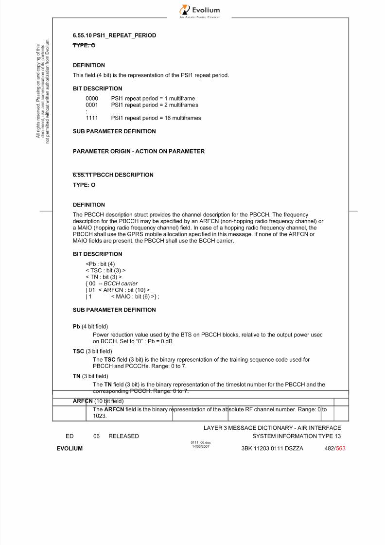
7/11/2019 1. Layer3 Air Interface Messages 0111_06
http://slidepdf.com/reader/full/1-layer3-air-interface-messages-011106 482/562
LAYER 3 MESSAGE DICTIONARY - AIR INTERFACE
ED 06 RELEASED SYSTEM INFORMATION TYPE 13
EVOLIUM
0111_06.doc14/03/2007
3BK 11203 0111 DSZZA 482/ 563
6.55.10 PSI1_REPEAT_PERIOD
TYPE: O
DEFINITION
This field (4 bit) is the representation of the PSI1 repeat period.
BIT DESCRIPTION
0000 PSI1 repeat period = 1 multiframe0001 PSI1 repeat period = 2 multiframes:1111 PSI1 repeat period = 16 multiframes
SUB PARAMETER DEFINITION
PARAMETER ORIGIN - ACTION ON PARAMETER
6.55.11 PBCCH DESCRIPTION
TYPE: O
DEFINITION
The PBCCH description struct provides the channel description for the PBCCH. The frequencydescription for the PBCCH may be specified by an ARFCN (non-hopping radio frequency channel) or a MAIO (hopping radio frequency channel) field. In case of a hopping radio frequency channel, thePBCCH shall use the GPRS mobile allocation specified in this message. If none of the ARFCN or MAIO fields are present, the PBCCH shall use the BCCH carrier.
BIT DESCRIPTION
<Pb : bit (4)< TSC : bit (3) >< TN : bit (3) >{ 00 -- BCCH carrier | 01 < ARFCN : bit (10) >| 1 < MAIO : bit (6) >} ;
SUB PARAMETER DEFINITION
Pb (4 bit field)
Power reduction value used by the BTS on PBCCH blocks, relative to the output power usedon BCCH. Set to “0” : Pb = 0 dB
TSC (3 bit field)
The TSC field (3 bit) is the binary representation of the training sequence code used for PBCCH and PCCCHs. Range: 0 to 7.
TN (3 bit field)
The TN field (3 bit) is the binary representation of the timeslot number for the PBCCH and thecorresponding PCCCH. Range: 0 to 7.
ARFCN (10 bit field)
The ARFCN field is the binary representation of the absolute RF channel number. Range: 0 to1023.
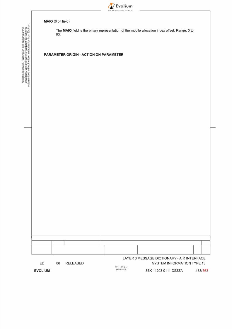
7/11/2019 1. Layer3 Air Interface Messages 0111_06
http://slidepdf.com/reader/full/1-layer3-air-interface-messages-011106 483/562
LAYER 3 MESSAGE DICTIONARY - AIR INTERFACE
ED 06 RELEASED SYSTEM INFORMATION TYPE 13
EVOLIUM
0111_06.doc14/03/2007
3BK 11203 0111 DSZZA 483/ 563
MAIO (6 bit field)
The MAIO field is the binary representation of the mobile allocation index offset. Range: 0 to63.
PARAMETER ORIGIN - ACTION ON PARAMETER
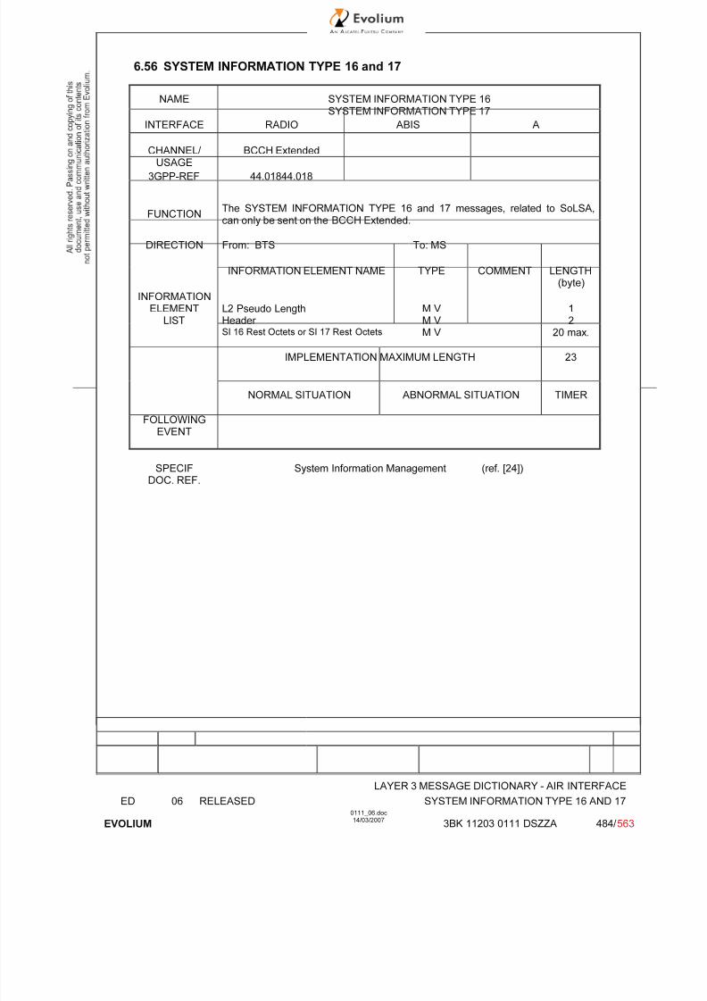
7/11/2019 1. Layer3 Air Interface Messages 0111_06
http://slidepdf.com/reader/full/1-layer3-air-interface-messages-011106 484/562
LAYER 3 MESSAGE DICTIONARY - AIR INTERFACE
ED 06 RELEASED SYSTEM INFORMATION TYPE 16 AND 17
EVOLIUM
0111_06.doc14/03/2007
3BK 11203 0111 DSZZA 484/ 563
6.56 SYSTEM INFORMATION TYPE 16 and 17
NAME SYSTEM INFORMATION TYPE 16SYSTEM INFORMATION TYPE 17
INTERFACE RADIO ABIS A
CHANNEL/ USAGE BCCH Extended
3GPP-REF 44.01844.018
FUNCTIONThe SYSTEM INFORMATION TYPE 16 and 17 messages, related to SoLSA,can only be sent on the BCCH Extended.
DIRECTION From: BTS To: MS
INFORMATION ELEMENT NAME TYPE COMMENT LENGTH(byte)
INFORMATION
ELEMENTLIST
L2 Pseudo LengthHeader SI 16 Rest Octets or SI 17 Rest Octets
M V M V M V
12
20 max.
IMPLEMENTATION MAXIMUM LENGTH 23
NORMAL SITUATION ABNORMAL SITUATION TIMER
FOLLOWINGEVENT
SPECIFDOC. REF.
System Information Management (ref. [24])

7/11/2019 1. Layer3 Air Interface Messages 0111_06
http://slidepdf.com/reader/full/1-layer3-air-interface-messages-011106 485/562
LAYER 3 MESSAGE DICTIONARY - AIR INTERFACE
ED 06 RELEASED SYSTEM INFORMATION TYPE 16 AND 17
EVOLIUM
0111_06.doc14/03/2007
3BK 11203 0111 DSZZA 485/ 563
6.56.1 GENERAL DESCRIPTION
SYSTEM INFORMATION TYPE 16:
8 7 6 5 4 3 2 1
L2 Pseudo Length L2 Pseudo Length Value=1 0 1
0 0 0 0 0 1 1 0
0 0 1 1 1 1 0 1
SI 16 Rest Octets See the table below for the detail
(20 bytes maximum)
SYSTEM INFORMATION TYPE 17:
8 7 6 5 4 3 2 1
L2 Pseudo Length L2 Pseudo Length Value=1 0 1
0 0 0 0 0 1 1 0
0 0 1 1 1 1 1 0
SI 17 Rest Octets See the table below for the detail
(20 bytes maximum)
SI 16 or SI 17 Rest Octets Rest Octets detail description:
Information elements Length(bit)
Coding rules
1 Set to ‘H’ (LSA Parameters are included)
PRIO_THR 3 See §6.56.2 for coding.
LSA_OFFSET 3 See §6.56.3 for coding.
1 Set to ‘0’ (Exclusive MCC and MNC are notincluded)
LSA ID information152
maximum
A list of LSA_IDs can be added until the 20 octets of the SI 16 or SI 17 Rest Octets Rest Octets are full, see§6.56.4 for detail.

7/11/2019 1. Layer3 Air Interface Messages 0111_06
http://slidepdf.com/reader/full/1-layer3-air-interface-messages-011106 486/562
LAYER 3 MESSAGE DICTIONARY - AIR INTERFACE
ED 06 RELEASED SYSTEM INFORMATION TYPE 16 AND 17
EVOLIUM
0111_06.doc14/03/2007
3BK 11203 0111 DSZZA 486/ 563

7/11/2019 1. Layer3 Air Interface Messages 0111_06
http://slidepdf.com/reader/full/1-layer3-air-interface-messages-011106 487/562
LAYER 3 MESSAGE DICTIONARY - AIR INTERFACE
ED 06 RELEASED SYSTEM INFORMATION TYPE 16 AND 17
EVOLIUM
0111_06.doc14/03/2007
3BK 11203 0111 DSZZA 487/ 563
6.56.2 PRIO_THR
TYPE: M
DEFINITION
The PRIO_THR field is a signal threshold used by the mobile station to determine whether prioritised
cell re-selection shall apply. The use and coding of this parameters is defined in 3GPP TS 05.08.
BIT DESCRIPTION
SUB PARAMETER DEFINITION
PARAMETER ORIGIN - ACTION ON PARAMETER
6.56.3 LSA_OFFSET
TYPE: M
DEFINITION
The LSA_OFFSET field applies an offset for LSA reselection between cells with same LSA priorities.The use and coding of this parameters is defined in 3GPP TS 05.08.
BIT DESCRIPTION
SUB PARAMETER DEFINITION
PARAMETER ORIGIN - ACTION ON PARAMETER
6.56.4 LSA ID INFORMATION
TYPE: M
DEFINITIONThe purpose of the LSA_ID field is to identify a LSA (Localised Service Area).
BIT DESCRIPTION
<LSA ID information> ::= <LSA identity>{0 | 1 <LSA ID information>};
<LSA identity> ::= {0 <LSA_ID : bit (24)>
|1 <ShortLSA_ID : bit (10)>}.
Note: maximum of 5 long LSA_IDs (24 bits), or 12 ShortLSA_IDs (10 bits), or a mixture of the twocould be accomodated within SI 16 or SI17 message.

7/11/2019 1. Layer3 Air Interface Messages 0111_06
http://slidepdf.com/reader/full/1-layer3-air-interface-messages-011106 488/562
LAYER 3 MESSAGE DICTIONARY - AIR INTERFACE
ED 06 RELEASED SYSTEM INFORMATION TYPE 16 AND 17
EVOLIUM
0111_06.doc14/03/2007
3BK 11203 0111 DSZZA 488/ 563
SUB PARAMETER DEFINITION
PARAMETER ORIGIN - ACTION ON PARAMETER

7/11/2019 1. Layer3 Air Interface Messages 0111_06
http://slidepdf.com/reader/full/1-layer3-air-interface-messages-011106 489/562
LAYER 3 MESSAGE DICTIONARY - AIR INTERFACE
ED 06 RELEASED TALKER INDICATION
EVOLIUM
0111_06.doc14/03/2007
3BK 11203 0111 DSZZA 489/ 563
6.57 TALKER INDICATION
NAME TALKER INDICATION
INTERFACE RADIO ABIS A
CHANNEL/ USAGE
FACCH
3GPP-REF 44.018
FUNCTION This message is sent by the mobile station to the network to give the talker information when a new layer 2 connection is established on a VGCS channelafter an uplink access.
DIRECTION From: MS To: BTS
INFORMATION ELEMENT NAME TYPE COMMENT
LENGTH(byte)
INFORMATIONELEMENT
LISTHeader Mobile Station Classmark 2Mobile Identity
M LV M LV
24
2-9
IMPLEMENTATION MAXIMUM LENGTH 16
NORMAL SITUATION ABNORMAL SITUATION TIMER
FOLLOWINGEVENT
SPECIFDOC. REF.
See ref [36]

7/11/2019 1. Layer3 Air Interface Messages 0111_06
http://slidepdf.com/reader/full/1-layer3-air-interface-messages-011106 490/562
LAYER 3 MESSAGE DICTIONARY - AIR INTERFACE
ED 06 RELEASED TALKER INDICATION
EVOLIUM
0111_06.doc14/03/2007
3BK 11203 0111 DSZZA 490/ 563
6.57.1 GENERAL DESCRIPTION
8 7 6 5 4 3 2 10 0 0 0 0 1 1 0
0 0 0 1 0 0 0 1
Length of MS classmark 2 contents
Mobile StationClassmark 2
0spare
Revisionlevel
ES-IND
A5/1 RF power Capability
0spare
PSCapa.
SS Screen.Indicator
SM.cap VBS VGCS
FC
CM3 0
spare
LCS
VACAP
UCS2 SoLSA CMSP A5/3 A5/2
Length of Mobile Identity contents
ID digit 1 OEI Type of ID
Mobile ID digit 3 ID digit 2
Identity ... ...
ID digit p+1 ID digit p
6.57.2 MS Classmark 2
TYPE: M
DEFINITION Defines certain attributes of the Mobile Station equipment in use on a particular transaction.
BIT DESCRIPTION
8 7 6 5 4 3 2 1
Length 1
0spare
Revisionlevel
ESIND
A5/1 RF power Capability
2
0spare
PSCapa.
SS Screen.Indicator
SM.cap VBS VGCS
FC 3
CM30
spareLCSVA
CAP
UCS2 SoLSA CMSP A5/3 A5/24
Bit 8 of octet 2 spare set to 0Bits 8 of octet 3 spare set to 0
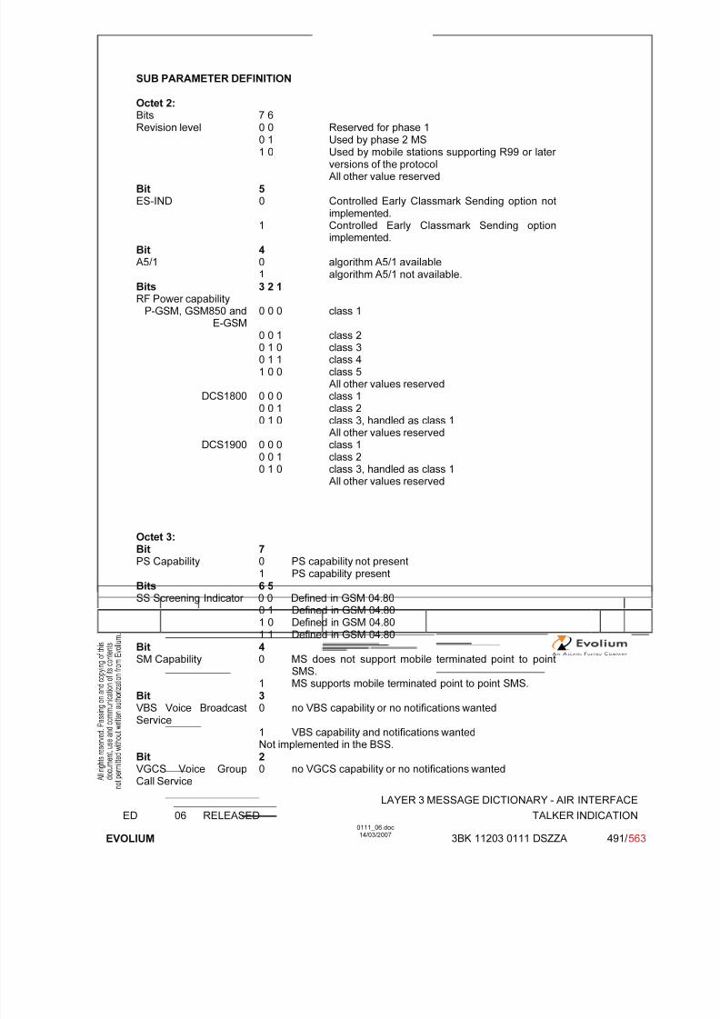
7/11/2019 1. Layer3 Air Interface Messages 0111_06
http://slidepdf.com/reader/full/1-layer3-air-interface-messages-011106 491/562
LAYER 3 MESSAGE DICTIONARY - AIR INTERFACE
ED 06 RELEASED TALKER INDICATION
EVOLIUM
0111_06.doc14/03/2007
3BK 11203 0111 DSZZA 491/ 563
SUB PARAMETER DEFINITION
Octet 2:Bits 7 6Revision level 0 0 Reserved for phase 1
0 1 Used by phase 2 MS
1 0 Used by mobile stations supporting R99 or later versions of the protocol All other value reserved
Bit 5ES-IND 0 Controlled Early Classmark Sending option not
implemented.1 Controlled Early Classmark Sending option
implemented.Bit 4A5/1 0 algorithm A5/1 available
1 algorithm A5/1 not available.Bits 3 2 1RF Power capability
P-GSM, GSM850 andE-GSM
0 0 0 class 1
0 0 1 class 20 1 0 class 30 1 1 class 41 0 0 class 5
All other values reservedDCS1800 0 0 0 class 1
0 0 1 class 20 1 0 class 3, handled as class 1
All other values reservedDCS1900 0 0 0 class 1
0 0 1 class 2
0 1 0 class 3, handled as class 1All other values reserved
Octet 3:Bit 7PS Capability 0 PS capability not present
1 PS capability presentBits 6 5SS Screening Indicator 0 0 Defined in GSM 04.80
0 1 Defined in GSM 04.80
1 0 Defined in GSM 04.801 1 Defined in GSM 04.80Bit 4SM Capability 0 MS does not support mobile terminated point to point
SMS.1 MS supports mobile terminated point to point SMS.
Bit 3VBS Voice BroadcastService
0 no VBS capability or no notifications wanted
1 VBS capability and notifications wantedNot implemented in the BSS.
Bit 2VGCS Voice Group
Call Service
0 no VGCS capability or no notifications wanted

7/11/2019 1. Layer3 Air Interface Messages 0111_06
http://slidepdf.com/reader/full/1-layer3-air-interface-messages-011106 492/562
LAYER 3 MESSAGE DICTIONARY - AIR INTERFACE
ED 06 RELEASED TALKER INDICATION
EVOLIUM
0111_06.doc14/03/2007
3BK 11203 0111 DSZZA 492/ 563
1 VGCS capability and notifications wanted
Bit 1FC FrequencyCapability
GSM900 0 The MS does not support the extension band G1 inaddition to the primary GSM band.
1 The MS does support the extension band G1.GSM850, DCS1800,DCS1900
0 Reserved for future use
Note: only FC is checked in this release and only in GSM900 configuration.
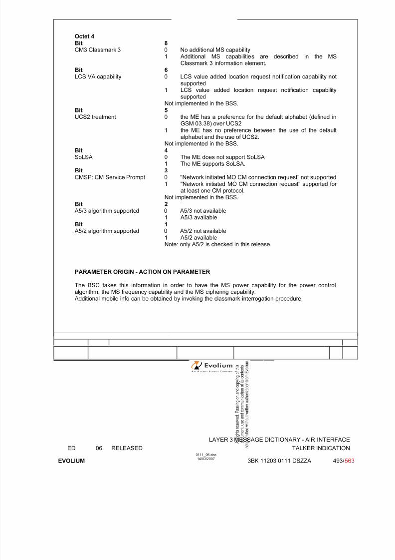
7/11/2019 1. Layer3 Air Interface Messages 0111_06
http://slidepdf.com/reader/full/1-layer3-air-interface-messages-011106 493/562
LAYER 3 MESSAGE DICTIONARY - AIR INTERFACE
ED 06 RELEASED TALKER INDICATION
EVOLIUM
0111_06.doc14/03/2007
3BK 11203 0111 DSZZA 493/ 563
Octet 4Bit 8CM3 Classmark 3 0 No additional MS capability
1 Additional MS capabilities are described in the MSClassmark 3 information element.
Bit 6LCS VA capability 0 LCS value added location request notification capability not
supported1 LCS value added location request notification capabilitysupported
Not implemented in the BSS.Bit 5UCS2 treatment 0 the ME has a preference for the default alphabet (defined in
GSM 03.38) over UCS21 the ME has no preference between the use of the default
alphabet and the use of UCS2.Not implemented in the BSS.
Bit 4SoLSA 0 The ME does not support SoLSA
1 The ME supports SoLSA.
Bit 3CMSP: CM Service Prompt 0 "Network initiated MO CM connection request" not supported1 "Network initiated MO CM connection request" supported for
at least one CM protocol.Not implemented in the BSS.
Bit 2A5/3 algorithm supported 0 A5/3 not available
1 A5/3 available
Bit 1A5/2 algorithm supported 0 A5/2 not available
1 A5/2 availableNote: only A5/2 is checked in this release.
PARAMETER ORIGIN - ACTION ON PARAMETER
The BSC takes this information in order to have the MS power capability for the power controlalgorithm, the MS frequency capability and the MS ciphering capability.Additional mobile info can be obtained by invoking the classmark interrogation procedure.

7/11/2019 1. Layer3 Air Interface Messages 0111_06
http://slidepdf.com/reader/full/1-layer3-air-interface-messages-011106 494/562
LAYER 3 MESSAGE DICTIONARY - AIR INTERFACE
ED 06 RELEASED TALKER INDICATION
EVOLIUM
0111_06.doc14/03/2007
3BK 11203 0111 DSZZA 494/ 563
6.57.3 Mobile Identity
TYPE: M
DEFINITIONTo provide either the IMSI, the TMSI or the IMEI. IMEISV is not used.
Note IMSI ≤ 15 digitsTMSI = 4 octetsIMEI = 15 digits
BIT DESCRIPTION
8 7 6 5 4 3 2 1
Length of Mobile Identity contents
ID digit 1 OEI Type of ID
ID digit 3 ID digit 2
: :
ID digit p+1 ID digit P
SUB PARAMETER DEFINITION
Type of ID: 0 0 1 IMSI0 1 0 IMEI Not used
0 1 1 IMEISV Not used1 0 0 TMSI0 0 0 No identity Not usedother values reserved
OEI: Odd Even Indicator
value 0: even number of identity digits (even for TMSI)1: odd number of digits
Filled digit :1 1 1 1
Octet 2
For the IMSI and the IMEI this field is coded using BCD coding. If the number of identify digits is eventhen bits 5 to 8 of the last octet shall be filled with an end mark coded as '1111'.If the mobile identity is the TMSI then bits 5 to 8 of octet 2 is coded as '1111' and bit 8 of octet 3 is themost significant bit, and bit 1 of the last octet is the least significant bit.
PARAMETER ORIGIN - ACTION ON PARAMETER

7/11/2019 1. Layer3 Air Interface Messages 0111_06
http://slidepdf.com/reader/full/1-layer3-air-interface-messages-011106 495/562
LAYER 3 MESSAGE DICTIONARY - AIR INTERFACE
ED 06 RELEASED UTRAN CLASSMARK CHANGE
EVOLIUM
0111_06.doc14/03/2007
3BK 11203 0111 DSZZA 495/ 563
6.58 UTRAN CLASSMARK CHANGE
NAME UTRAN CLASSMARK CHANGE
INTERFACE RADIO ABIS A
CHANNEL/ USAGE
FACCH/SDCCH Transparent
3GPP-REF 44.018 NA
FUNCTIONThis message is sent on the main DCCH by the mobile station to the network toindicate a UTRAN Classmark Change or as a response to a UTRAN classmarkenquiry.
DIRECTION From MS To BSS
INFORMATION ELEMENT NAME TYPE COMMENT LENGTH(byte)
INFORMATIONELEMENT
LISTHeader UTRAN Classmark
M V M LV
22-n
IMPLEMENTATION MAXIMUM LENGTH 4-n
NORMAL SITUATION ABNORMAL SITUATION TIMER
FOLLOWINGEVENT
BSC will forward the value part toMSC when 2G3G HO is
triggered.
SPECIFDOC. REF.
Classmark Handling [9]
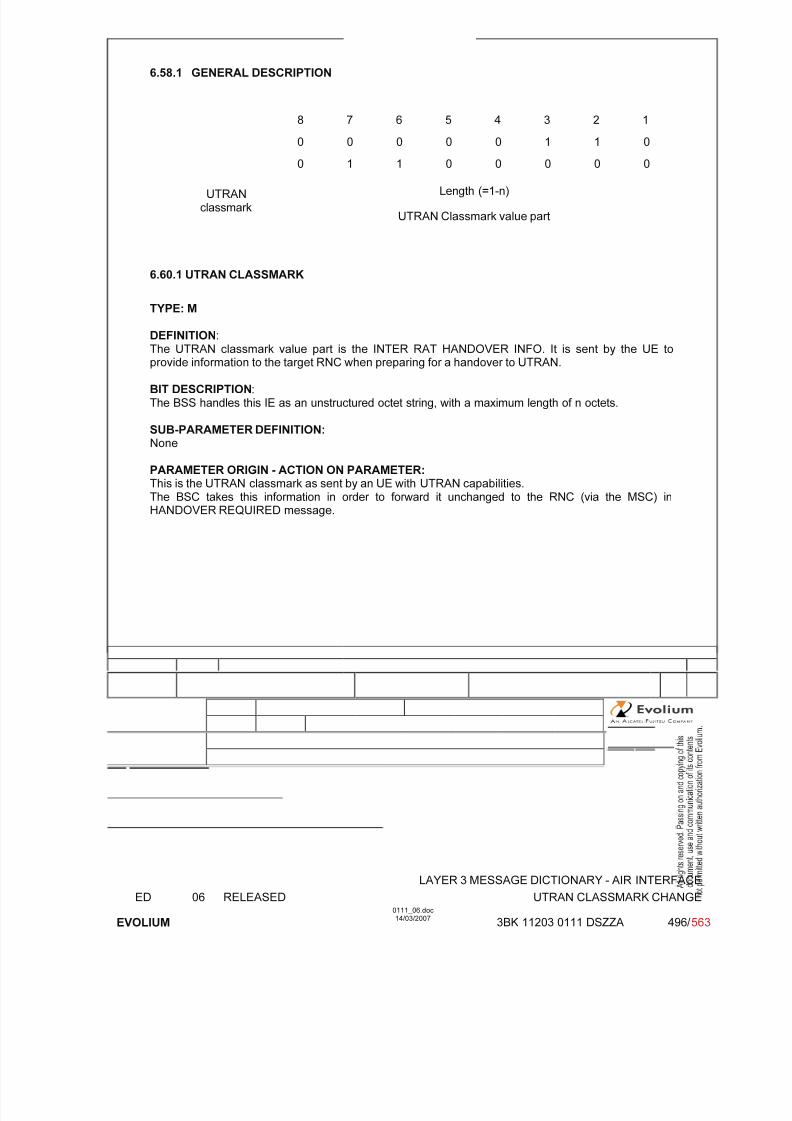
7/11/2019 1. Layer3 Air Interface Messages 0111_06
http://slidepdf.com/reader/full/1-layer3-air-interface-messages-011106 496/562
LAYER 3 MESSAGE DICTIONARY - AIR INTERFACE
ED 06 RELEASED UTRAN CLASSMARK CHANGE
EVOLIUM
0111_06.doc14/03/2007
3BK 11203 0111 DSZZA 496/ 563
6.58.1 GENERAL DESCRIPTION
8 7 6 5 4 3 2 1
0 0 0 0 0 1 1 0
0 1 1 0 0 0 0 0
Length (=1-n)UTRANclassmark
UTRAN Classmark value part
6.60.1 UTRAN CLASSMARK
TYPE: M
DEFINITION:
The UTRAN classmark value part is the INTER RAT HANDOVER INFO. It is sent by the UE toprovide information to the target RNC when preparing for a handover to UTRAN.
BIT DESCRIPTION:The BSS handles this IE as an unstructured octet string, with a maximum length of n octets.
SUB-PARAMETER DEFINITION: None
PARAMETER ORIGIN - ACTION ON PARAMETER:This is the UTRAN classmark as sent by an UE with UTRAN capabilities.The BSC takes this information in order to forward it unchanged to the RNC (via the MSC) inHANDOVER REQUIRED message.

7/11/2019 1. Layer3 Air Interface Messages 0111_06
http://slidepdf.com/reader/full/1-layer3-air-interface-messages-011106 497/562
LAYER 3 MESSAGE DICTIONARY - AIR INTERFACE
ED 06 RELEASED UPLINK ACCESS
EVOLIUM
0111_06.doc14/03/2007
3BK 11203 0111 DSZZA 497/ 563
6.59 UPLINK ACCESS
NAME UPLINK ACCESS
INTERFACE RADIO ABIS A
CHANNEL/ USAGE
RACH
3GPP-REF 44.018
FUNCTION This message is sent in random mode on the voice group call channel uplink. Itdoes not follow the basic format.
DIRECTION From: MS To: BTS
INFORMATION ELEMENT NAME TYPE COMMENT LENGTH(byte)
INFORMATIONELEMENT
LIST See the next page Unformatted 8bit field
1
IMPLEMENTATION MAXIMUM LENGTH 1
NORMAL SITUATION ABNORMAL SITUATION TIMER
FOLLOWINGEVENT
CHANNEL REQUIRED towardsthe BSC
_ _
SPECIFDOC. REF.
See ref [36]

7/11/2019 1. Layer3 Air Interface Messages 0111_06
http://slidepdf.com/reader/full/1-layer3-air-interface-messages-011106 498/562
LAYER 3 MESSAGE DICTIONARY - AIR INTERFACE
ED 06 RELEASED UPLINK ACCESS
EVOLIUM
0111_06.doc14/03/2007
3BK 11203 0111 DSZZA 498/ 563
6.59.1 GENERAL DESCRIPTION
8 7 6 5 4 3 2 1
Establ. Random
Cause Reference
6.59.2 ESTABLISHMENT CAUSE AND RANDOM REFERENCE
TYPE: M
DEFINITION
- ESTABLISHMENT CAUSE (octet 1)It indicates the reason for requesting the establishment of a connection. This field has a variablelength (from 3 bits up to 8 bits).
- RANDOM REFERENCE (octet 1) This is an unformatted field with variable length (from 5 bits down to 0 bits).
BIT DESCRIPTION The Uplink access message is coded as follows :(Random Reference field is filled with "x").
Message8 7 6 5 4 3 2 1
Meaning of Establishment Cause
1 1 0 x x x x x Subsequent talker uplink request
0 0 1 0 0 1 0 1 Reply on uplink access request
other values reserved for future use
PARAMETER ORIGIN - ACTION ON PARAMETER

7/11/2019 1. Layer3 Air Interface Messages 0111_06
http://slidepdf.com/reader/full/1-layer3-air-interface-messages-011106 499/562
LAYER 3 MESSAGE DICTIONARY - AIR INTERFACE
ED 06 RELEASED UPLINK BUSY
EVOLIUM
0111_06.doc14/03/2007
3BK 11203 0111 DSZZA 499/ 563
6.60 UPLINK BUSY
NAME UPLINK BUSY
INTERFACE RADIO ABIS A
CHANNEL/ USAGE
FACCH
3GPP-REF 44.018
FUNCTION This message is broadcasted by the network in unacknowledged mode to informthe mobile station of the uplink status of the voice group call channel.
DIRECTION From: BTS To: MS
INFORMATION ELEMENT NAME TYPE COMMENT
LENGTH(byte)
INFORMATIONELEMENT
LISTHeader 2
IMPLEMENTATION LENGTH 2
NORMAL SITUATION ABNORMAL SITUATION TIMER
FOLLOWINGEVENT
SPECIFDOC. REF. See ref [36]

7/11/2019 1. Layer3 Air Interface Messages 0111_06
http://slidepdf.com/reader/full/1-layer3-air-interface-messages-011106 500/562
LAYER 3 MESSAGE DICTIONARY - AIR INTERFACE
ED 06 RELEASED UPLINK BUSY
EVOLIUM
0111_06.doc14/03/2007
3BK 11203 0111 DSZZA 500/ 563
6.60.1 GENERAL DESCRIPTION
8 7 6 5 4 3 2 1
Skip indicator &Protocol discriminator
0 0 0 0 0 1 1 0
Message type 0 0 1 0 1 0 1 0
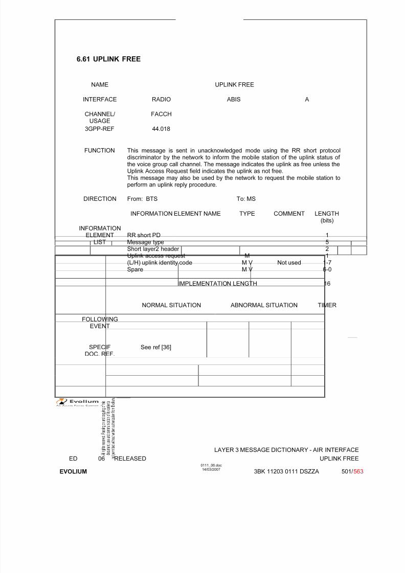
7/11/2019 1. Layer3 Air Interface Messages 0111_06
http://slidepdf.com/reader/full/1-layer3-air-interface-messages-011106 501/562
LAYER 3 MESSAGE DICTIONARY - AIR INTERFACE
ED 06 RELEASED UPLINK FREE
EVOLIUM
0111_06.doc14/03/2007
3BK 11203 0111 DSZZA 501/ 563
6.61 UPLINK FREE
NAME UPLINK FREE
INTERFACE RADIO ABIS A
CHANNEL/ USAGE
FACCH
3GPP-REF 44.018
FUNCTION This message is sent in unacknowledged mode using the RR short protocoldiscriminator by the network to inform the mobile station of the uplink status of the voice group call channel. The message indicates the uplink as free unless theUplink Access Request field indicates the uplink as not free.
This message may also be used by the network to request the mobile station toperform an uplink reply procedure.
DIRECTION From: BTS To: MS
INFORMATION ELEMENT NAME TYPE COMMENT LENGTH(bits)
INFORMATIONELEMENT
LISTRR short PDMessage typeShort layer2 header Uplink access request
(L/H) uplink identity codeSpare
M
M V M V Not used
1521
1-76-0
IMPLEMENTATION LENGTH 16
NORMAL SITUATION ABNORMAL SITUATION TIMER
FOLLOWINGEVENT
SPECIF
DOC. REF.
See ref [36]

7/11/2019 1. Layer3 Air Interface Messages 0111_06
http://slidepdf.com/reader/full/1-layer3-air-interface-messages-011106 502/562
LAYER 3 MESSAGE DICTIONARY - AIR INTERFACE
ED 06 RELEASED UPLINK FREE
EVOLIUM
0111_06.doc14/03/2007
3BK 11203 0111 DSZZA 502/ 563
6.61.1 GENERAL DESCRIPTION
8 7 6 5 4 3 2 1
"short header" RRshortPD
Message type Short layer 2header
L implicitspare
implicitspare
implicitspare
implicitspare
implicitspare
implicitspare
Uplinkaccessrequest H uplink identity code
6.61.2 UPLINK ACCESS REQUEST
TYPE: M
DEFINITION
L Mobile station shall not perform the uplink reply procedure;H Mobile station shall perform the uplink reply procedure.
When set to H, this element also indicates the uplink as not free for the uplink accessprocedure.
BIT DESCRIPTION One bit field

7/11/2019 1. Layer3 Air Interface Messages 0111_06
http://slidepdf.com/reader/full/1-layer3-air-interface-messages-011106 503/562
LAYER 3 MESSAGE DICTIONARY - AIR INTERFACE
ED 06 RELEASED UPLINK RELEASE
EVOLIUM
0111_06.doc14/03/2007
3BK 11203 0111 DSZZA 503/ 563
6.62 UPLINK RELEASE
NAME UPLINK RELEASE
INTERFACE RADIO ABIS A
CHANNEL/ USAGE
FACCH
3GPP-REF 44.018
FUNCTION This message is sent on the uplink of the voice group call channel to initiate adeactivation of the group transmit mode and to set the uplink free or on the uplinkby a talker on the dedicated channel or on the downlink of the voice group call
channel in order to reject an uplink access which was already granted by thenetwork
DIRECTION From: BTSFrom : MS
To: MSTo BTS
INFORMATION ELEMENT NAME TYPE COMMENT LENGTH(byte)
INFORMATIONELEMENT
LISTHeader RR Cause M V
21
IMPLEMENTATION LENGTH 3
NORMAL SITUATION ABNORMAL SITUATION TIMER
FOLLOWINGEVENT
SPECIFDOC. REF.
See ref [36]
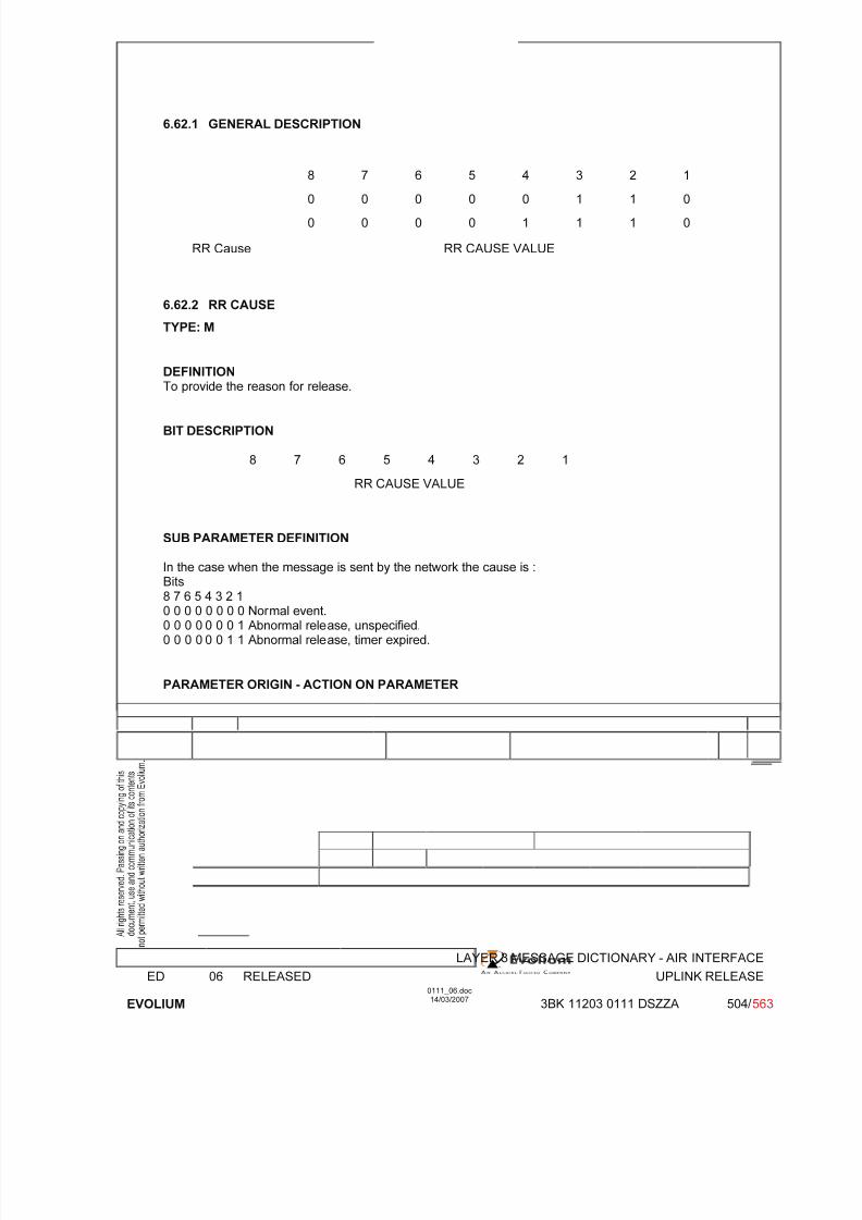
7/11/2019 1. Layer3 Air Interface Messages 0111_06
http://slidepdf.com/reader/full/1-layer3-air-interface-messages-011106 504/562
LAYER 3 MESSAGE DICTIONARY - AIR INTERFACE
ED 06 RELEASED UPLINK RELEASE
EVOLIUM
0111_06.doc14/03/2007
3BK 11203 0111 DSZZA 504/ 563
6.62.1 GENERAL DESCRIPTION
8 7 6 5 4 3 2 1
0 0 0 0 0 1 1 0
0 0 0 0 1 1 1 0
RR Cause RR CAUSE VALUE
6.62.2 RR CAUSE
TYPE: M
DEFINITIONTo provide the reason for release.
BIT DESCRIPTION
8 7 6 5 4 3 2 1
RR CAUSE VALUE
SUB PARAMETER DEFINITION
In the case when the message is sent by the network the cause is :Bits8 7 6 5 4 3 2 10 0 0 0 0 0 0 0 Normal event.0 0 0 0 0 0 0 1 Abnormal release, unspecified.0 0 0 0 0 0 1 1 Abnormal release, timer expired.
PARAMETER ORIGIN - ACTION ON PARAMETER
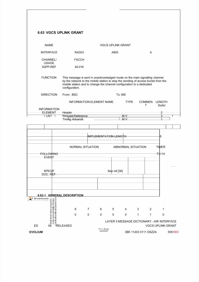
7/11/2019 1. Layer3 Air Interface Messages 0111_06
http://slidepdf.com/reader/full/1-layer3-air-interface-messages-011106 505/562
LAYER 3 MESSAGE DICTIONARY - AIR INTERFACE
ED 06 RELEASED VGCS UPLINK GRANT
EVOLIUM
0111_06.doc14/03/2007
3BK 11203 0111 DSZZA 505/ 563
6.63 VGCS UPLINK GRANT
NAME VGCS UPLINK GRANT
INTERFACE RADIO ABIS A
CHANNEL/ USAGE
FACCH
3GPP-REF 44.018
FUNCTION This message is sent in unacknowledged mode on the main signalling channelby the network to the mobile station to stop the sending of access bursts from themobile station and to change the channel configuration to a dedicated
configuration.
DIRECTION From: BSC To: MS
INFORMATION ELEMENT NAME TYPE COMMENT
LENGTH(byte)
INFORMATIONELEMENT
LISTHeader Request ReferenceTiming Advance
M V M V
231
IMPLEMENTATION LENGTH 6
NORMAL SITUATION ABNORMAL SITUATION TIMER
FOLLOWINGEVENT
T3115
SPECIF
DOC. REF.
See ref [36]
6.63.1 GENERAL DESCRIPTION
8 7 6 5 4 3 2 1
0 0 0 0 0 1 1 0
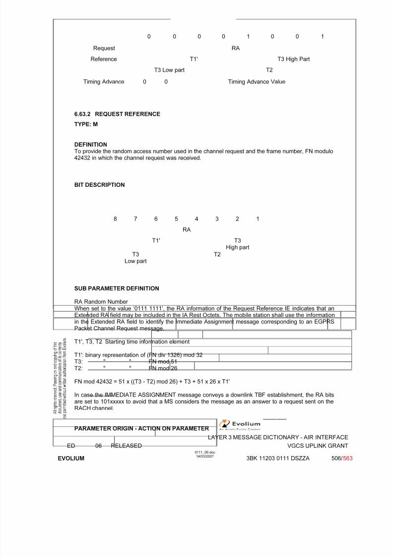
7/11/2019 1. Layer3 Air Interface Messages 0111_06
http://slidepdf.com/reader/full/1-layer3-air-interface-messages-011106 506/562
LAYER 3 MESSAGE DICTIONARY - AIR INTERFACE
ED 06 RELEASED VGCS UPLINK GRANT
EVOLIUM
0111_06.doc14/03/2007
3BK 11203 0111 DSZZA 506/ 563
0 0 0 0 1 0 0 1
Request RA
Reference T1' T3 High Part
T3 Low part T2
Timing Advance 0 0 Timing Advance Value
6.63.2 REQUEST REFERENCE
TYPE: M
DEFINITIONTo provide the random access number used in the channel request and the frame number, FN modulo42432 in which the channel request was received.
BIT DESCRIPTION
8 7 6 5 4 3 2 1
RA
T1' T3High part
T3Low part T2
SUB PARAMETER DEFINITION
RA Random Number When set to the value ‘0111 1111’, the RA information of the Request Reference IE indicates that anExtended RA field may be included in the IA Rest Octets. The mobile station shall use the informationin the Extended RA field to identify the Immediate Assignment message corresponding to an EGPRSPacket Channel Request message.
T1', T3, T2 Starting time information element
T1': binary representation of (FN div 1326) mod 32T3: " " FN mod 51T2: " " FN mod 26
FN mod 42432 = 51 x ((T3 - T2) mod 26) + T3 + 51 x 26 x T1'
In case the IMMEDIATE ASSIGNMENT message conveys a downlink TBF establishment, the RA bitsare set to 101xxxxx to avoid that a MS considers the message as an answer to a request sent on theRACH channel.
PARAMETER ORIGIN - ACTION ON PARAMETER

7/11/2019 1. Layer3 Air Interface Messages 0111_06
http://slidepdf.com/reader/full/1-layer3-air-interface-messages-011106 507/562
LAYER 3 MESSAGE DICTIONARY - AIR INTERFACE
ED 06 RELEASED VGCS UPLINK GRANT
EVOLIUM
0111_06.doc14/03/2007
3BK 11203 0111 DSZZA 507/ 563
RA: This information comes from the MS in Channel Required message addressed by the BTS. It isused to allow the MS to recognise its own request among those sent by the BSC at the same time.
T1', T3, T2 are also stored from Channel Required message Time of arrival (in terms of FrameNumber) of the Access Burst given by the BTS in the Channel Required message.
6.63.3 TIMING ADVANCE
TYPE: M
DEFINITIONTo provide Timing Advance value
BIT DESCRIPTION
8 7 6 5 4 3 2 1
0 0 Timing Advance Value
Bits 7, 8 are spare bits.
SUB PARAMETER DEFINITION
Binary representation of the timing advance in bit periods (1 bit period 48/13 s).
PARAMETER ORIGIN - ACTION ON PARAMETER
The access delay is stored by the BSC and sent to the MS as Timing advance.

7/11/2019 1. Layer3 Air Interface Messages 0111_06
http://slidepdf.com/reader/full/1-layer3-air-interface-messages-011106 508/562
LAYER 3 MESSAGE DICTIONARY - AIR INTERFACE
ED 06 RELEASED SMSCB MESSAGES
EVOLIUM
0111_06.doc14/03/2007
3BK 11203 0111 DSZZA 508/ 563
7 RADIO INTERFACE MESSAGES FOR SMSCB

7/11/2019 1. Layer3 Air Interface Messages 0111_06
http://slidepdf.com/reader/full/1-layer3-air-interface-messages-011106 509/562
LAYER 3 MESSAGE DICTIONARY - AIR INTERFACE
ED 06 RELEASED MESSAGE BLOCKS
EVOLIUM
0111_06.doc14/03/2007
3BK 11203 0111 DSZZA 509/ 563
7.1 MESSAGE BLOCKS
NAME MESSAGE BLOCKS
INTERFACE RADIO ABIS A
CHANNEL/ USAGE CBCH BTS Transparent
3GPP-REF 24.012
FUNCTION A CB message consists of a 88 octets of information. The 88 octet block issegmented into four 22 octet blocks. A 1 octet Block type is added as a header toeach 22 octet block. The overall blocks are thus 23 octets in length.The message blocks are sent on the CBCH by the network to all the MobileStations which are in idle mode in the cell. SMSCB message carries one page of CB information message (made of up to 15 pages) which may come fromdifferent sources and gives information (eg. traffic or weather reports) to the MSof a geographical area.
DIRECTION From: BTS To: MS
INFORMATION ELEMENT NAME TYPE COMMENT LENGTH
INFORMATIONELEMENT
LIST See following pages for thedescription.
IMPLEMENTATION MAXIMUM LENGTH 92
NORMAL SITUATION ABNORMAL SITUATION TIMER
FOLLOWINGEVENT
SPECIFDOC. REF.
SMSCB (ref. [23])

7/11/2019 1. Layer3 Air Interface Messages 0111_06
http://slidepdf.com/reader/full/1-layer3-air-interface-messages-011106 510/562
LAYER 3 MESSAGE DICTIONARY - AIR INTERFACE
ED 06 RELEASED MESSAGE BLOCKS
EVOLIUM
0111_06.doc14/03/2007
3BK 11203 0111 DSZZA 510/ 563
7.1.1 GENERAL DESCRIPTION
7.1.1.1 Normal message blocks
8 7 6 5 4 3 2 1
Spare LPD LB Sequence Number octet 1
0 0 1 0 0 0 0 0
First Block octet 2
SMSCB INFORMATION
octet23
Spare LPD LB Sequence Number octet24
0 0 1 0 0 0 0 1
Second Block octet25
SMSCB INFORMATION
octet46
Spare LPD LB Sequence Number octet47
0 0 1 0 0 0 1 0
Third Block octet48
SMSCB INFORMATION
octet69
Spare LPD LB Sequence Number octet70
0 0 1 1 0 0 1 1
Fourth Block octet71
SMSCB INFORMATION
octet92
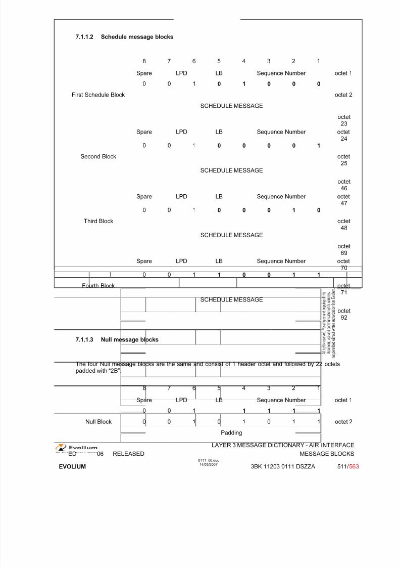
7/11/2019 1. Layer3 Air Interface Messages 0111_06
http://slidepdf.com/reader/full/1-layer3-air-interface-messages-011106 511/562
LAYER 3 MESSAGE DICTIONARY - AIR INTERFACE
ED 06 RELEASED MESSAGE BLOCKS
EVOLIUM
0111_06.doc14/03/2007
3BK 11203 0111 DSZZA 511/ 563
7.1.1.2 Schedule message blocks
8 7 6 5 4 3 2 1
Spare LPD LB Sequence Number octet 1
0 0 1 0 1 0 0 0
First Schedule Block octet 2
SCHEDULE MESSAGE
octet23
Spare LPD LB Sequence Number octet24
0 0 1 0 0 0 0 1
Second Block octet25
SCHEDULE MESSAGE
octet46
Spare LPD LB Sequence Number octet47
0 0 1 0 0 0 1 0
Third Block octet48
SCHEDULE MESSAGE
octet69
Spare LPD LB Sequence Number octet70
0 0 1 1 0 0 1 1
Fourth Block octet71
SCHEDULE MESSAGE
octet92
7.1.1.3 Null message blocks
The four Null message blocks are the same and consist of 1 header octet and followed by 22 octetspadded with “2B”.
8 7 6 5 4 3 2 1
Spare LPD LB Sequence Number octet 1
0 0 1 1 1 1 1
Null Block 0 0 1 0 1 0 1 1 octet 2
Padding
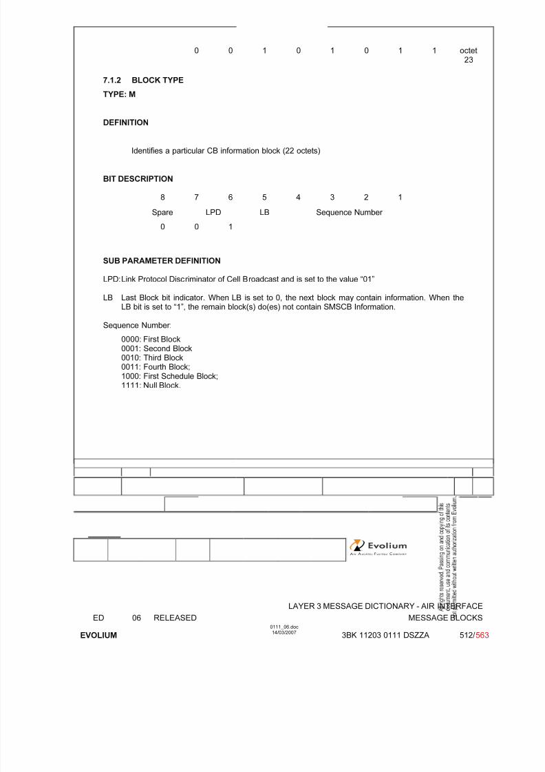
7/11/2019 1. Layer3 Air Interface Messages 0111_06
http://slidepdf.com/reader/full/1-layer3-air-interface-messages-011106 512/562
LAYER 3 MESSAGE DICTIONARY - AIR INTERFACE
ED 06 RELEASED MESSAGE BLOCKS
EVOLIUM
0111_06.doc14/03/2007
3BK 11203 0111 DSZZA 512/ 563
0 0 1 0 1 0 1 1 octet23
7.1.2 BLOCK TYPE
TYPE: M
DEFINITION
Identifies a particular CB information block (22 octets)
BIT DESCRIPTION
8 7 6 5 4 3 2 1
Spare LPD LB Sequence Number
0 0 1
SUB PARAMETER DEFINITION
LPD: Link Protocol Discriminator of Cell Broadcast and is set to the value “01”
LB Last Block bit indicator. When LB is set to 0, the next block may contain information. When theLB bit is set to “1”, the remain block(s) do(es) not contain SMSCB Information.
Sequence Number:
0000: First Block0001: Second Block
0010: Third Block0011: Fourth Block;1000: First Schedule Block;1111: Null Block.

7/11/2019 1. Layer3 Air Interface Messages 0111_06
http://slidepdf.com/reader/full/1-layer3-air-interface-messages-011106 513/562
LAYER 3 MESSAGE DICTIONARY - AIR INTERFACE
ED 06 RELEASED (E)GPRS MESSAGES
EVOLIUM
0111_06.doc14/03/2007
3BK 11203 0111 DSZZA 513/ 563
7.2 SMSCB SCHEDULE MESSAGE
NAME SMSCB SCHEDULE MESSAGE
INTERFACE RADIO ABIS A
CHANNEL/ USAGE
CBCH BTS Transparent
3GPP-REF 24.012
FUNCTION This message gives information relating to the CB information messages sentimmediately afterwards when DRX is activated.
DIRECTION From: BTS To: MS
INFORMATION ELEMENT NAME TYPE OMMENT LENGTH(byte)
INFORMATIONELEMENT
LISTSchedule message header New CBSMS Message BitmapNew CBSMS Message DescriptionOther Message DescriptionsPadding
M V M V O V O V O V
26
2-801-801-21
IMPLEMENTATION MAXIMUM LENGTH 88
NORMAL SITUATION ABNORMAL SITUATION TIMER
FOLLOWINGEVENT
SPECIFDOC. REF.
SMSCB (ref. [23])

7/11/2019 1. Layer3 Air Interface Messages 0111_06
http://slidepdf.com/reader/full/1-layer3-air-interface-messages-011106 514/562
LAYER 3 MESSAGE DICTIONARY - AIR INTERFACE
ED 06 RELEASED (E)GPRS MESSAGES
EVOLIUM
0111_06.doc14/03/2007
3BK 11203 0111 DSZZA 514/ 563
7.2.1 GENERAL DESCRIPTION
7.2.1.1 Schedule Message
8 7 6 5 4 3 2 1
Schedule message
header
Type
0 0
Begin Slot Number = 1 octet 1
spare0
spare0
End Slot Number = SCHEDULE_PERIOD octet 2
New CBSMSMessage Bitmap
NM 11
NM 2 NM 3 NM 4 NM 5 NM 6 NM 7 NM 8 octet 3
: :
NM 41 NM 42 NM 43 NM 44 NM 45 NM 46 NM 47 NM 48 octet 8
MDT
1
Message Identifier (High) octet 9
Message Identifier (Low) octet 10
: :
New CBSMS Message
MDT1
Message Identifier (High)
Description Message Identifier (Low)
MDT Repeated Message Slot Number
0 0
: :
MDT
1
Message Identifier (High)
Other MessageMessage Identifier (Low)
Descriptions : :
MDT1
Message Identifier (High)
Message Identifier (Low)
MDT Repeated Message Slot Number
0 0
: :
0 0 1 0 1 0 1 10 0 1 0 1 0 1 1
Padding : :
0 0 1 0 1 0 1 1 Note 1
Note 1: Octet 22, if the first block does not fill the 22 bytes;Octet 44, if the second block does not fill the 22 bytes;Octet 66, if the third block does not fill the 22 bytes;Octet 88, if the fourth block does not fill the 22 bytes.

7/11/2019 1. Layer3 Air Interface Messages 0111_06
http://slidepdf.com/reader/full/1-layer3-air-interface-messages-011106 515/562
LAYER 3 MESSAGE DICTIONARY - AIR INTERFACE
ED 06 RELEASED (E)GPRS MESSAGES
EVOLIUM
0111_06.doc14/03/2007
3BK 11203 0111 DSZZA 515/ 563
7.2.1.2 Unscheduled Schedule Message
The unscheduled schedule message differs from the schedule message only with Begin Slot Number which should be in range [2, SP].
8 7 6 5 4 3 2 1
Schedule messageheader
Type0 0
Begin Slot Number > 1 octet 1
spare0
spare0
End Slot Number octet 2
New CBSMS
NM 10
NM 2 NM 3 NM 4 NM 5 NM 6 NM 7 NM 8 octet 3
Message Bitmap : :
NM 41 NM 42 NM 43 NM 44 NM 45 NM 46 NM 47 NM 48 octet 8
MDT1
Message Identifier (High) octet 9
Message Identifier (Low) octet 10
: :
New CBSMS Message
MDT1
Message Identifier (High)
Description Message Identifier (Low)
MDT Repeated Message Slot Number
0 0
: :
MDT
1
Message Identifier (High)
Other MessageMessage Identifier (Low)
Descriptions : :
MDT1
Message Identifier (High)
Message Identifier (Low)
MDT Repeated Message Slot Number
0 0 0 0 0 0 0 1
: :
0 0 1 0 1 0 1 1
Padding : Padding :
0 0 1 0 1 0 1 1 Note 1
Note 1: Octet 22, if the first block does not fill the 22 bytes;Octet 44, if the second block does not fill the 22 bytes;Octet 66, if the third block does not fill the 22 bytes;Octet 88, if the fourth block does not fill the 22 bytes.

7/11/2019 1. Layer3 Air Interface Messages 0111_06
http://slidepdf.com/reader/full/1-layer3-air-interface-messages-011106 516/562
LAYER 3 MESSAGE DICTIONARY - AIR INTERFACE
ED 06 RELEASED (E)GPRS MESSAGES
EVOLIUM
0111_06.doc14/03/2007
3BK 11203 0111 DSZZA 516/ 563
7.2.1.3 Null Message transmission
8 7 6 5 4 3 2 1
Schedule messageheader
Type0 0
Begin Slot Number = 1 octet 1
spare0
spare0
End Slot Number octet 2
NM 10
NM 20
NM 30
NM 40
NM 50
NM 60
NM 70
NM 80
octet 3
New CBSMSMessage Bitmap : :
NM 410
NM 420
NM 430
NM 440
NM 450
NM 460
NM 470
NM 480
octet 8
MDT
0 1 0 0 0 0 0 0 octet 9
New CBSMS MessageDescription : :
0 1 0 0 0 0 0 0 octet SP+9(Note 1)
0 0 1 0 1 0 1 1 ctet SP+10
Padding
: :
0 0 1 0 1 0 1 1 (Note 2)
Note 1: SP (Schedule Period), the maximum value is 40Note 2: Octet 22, if the first block does not fill the 22 bytes;
Octet 44, if the second block does not fill the 22 bytes;Octet 66, if the third block does not fill the 22 bytes;

7/11/2019 1. Layer3 Air Interface Messages 0111_06
http://slidepdf.com/reader/full/1-layer3-air-interface-messages-011106 517/562
LAYER 3 MESSAGE DICTIONARY - AIR INTERFACE
ED 06 RELEASED (E)GPRS MESSAGES
EVOLIUM
0111_06.doc14/03/2007
3BK 11203 0111 DSZZA 517/ 563
7.2.2 SCHEDULE MESSAGE HEADER
TYPE: M
DEFINITION
Indicates the Schedule Message Type and defines the Schedule Period.
BIT DESCRIPTION
8 7 6 5 4 3 2 1
Type0 0
Begin Slot Number
spare0
spare0
End Slot Number
SUB PARAMETER DEFINITION
Type:Schedule Message Type is always set to 0 0.
Begin Slot Number:First message slot number relative to the Schedule Period following the Schedule Message.The Begin Slot Number field is coded in binary.Value range: 1 to 48.
End Slot Number:Last message slot number relative to the Schedule Period following the Schedule Message.The End Slot Number field is coded in binary, and its value must be greater than or equal tothe value of Begin Slot Number.Value range: 1 to 48.
PARAMETER ORIGIN - ACTION ON PARAMETER

7/11/2019 1. Layer3 Air Interface Messages 0111_06
http://slidepdf.com/reader/full/1-layer3-air-interface-messages-011106 518/562
LAYER 3 MESSAGE DICTIONARY - AIR INTERFACE
ED 06 RELEASED (E)GPRS MESSAGES
EVOLIUM
0111_06.doc14/03/2007
3BK 11203 0111 DSZZA 518/ 563
7.2.3 NEW CBSMS MESSAGE BITMAP
TYPE: M
DEFINITION
Defines the contents of message slots of the Schedule Period described in the ScheduleMessage.
BIT DESCRIPTION
8 7 6 5 4 3 2 1
NM 1 NM 2 NM 3 NM 4 NM 5 NM 6 NM 7 NM 8
NM 9 NM 10 NM 11 NM 12 NM 13 NM 14 NM 15 NM 16
NM 17 NM 18 NM 19 NM 20 NM 21 NM 22 NM 23 NM 24
NM 25 NM 26 NM 27 NM 28 NM 29 NM 30 NM 31 NM 32
NM 33 NM 34 NM 35 NM 36 NM 37 NM 38 NM 39 NM 40
NM 41 NM 42 NM 43 NM 44 NM 45 NM 46 NM 47 NM 48
SUB PARAMETER DEFINITION
NM i: The New Message bit i refers to the content of message slot i. Its meaning is as follows:1 The message slot contains an SMSCB message page which was either not sent during the
previous schedule period, or sent unscheduled during the preceding schedule period; or, themessage is indicated as of free usage, reading advised. The value is 1 both for the first
transmission of a given SMSCB message page in the schedule period or a repetition of it withinthe schedule period.
0 The message slot is such that value 1 is not suitable.
PARAMETER ORIGIN - ACTION ON PARAMETER
7.2.4 NEW CBSMS MESSAGE DESCRIPTION
TYPE: O
DEFINITION
Contains as many Message Descriptions as there are bits set to 1 in the New CBSMSMessage Bitmap. A Message Description is 1 or 2 octets long.

7/11/2019 1. Layer3 Air Interface Messages 0111_06
http://slidepdf.com/reader/full/1-layer3-air-interface-messages-011106 519/562
LAYER 3 MESSAGE DICTIONARY - AIR INTERFACE
ED 06 RELEASED (E)GPRS MESSAGES
EVOLIUM
0111_06.doc14/03/2007
3BK 11203 0111 DSZZA 519/ 563
BIT DESCRIPTION
First transmission of an SMSCB within the Schedule Period
8 7 6 5 4 3 2 1
MDT Message Identifier (high part) Octet 1
1
Message Identifier (low part) Octet 2
Retransmission indication
8 7 6 5 4 3 2 1
MDT Octet 10 0 Repeated Message Slot Number
Free Message Slot, optional reading
8 7 6 5 4 3 2 1
MDT 10 1 0 0 0 0 0 0
Free Message Slot, reading advised
8 7 6 5 4 3 2 1
MDT 10 1 0 0 0 0 0 1
SUB PARAMETER DEFINITION
MDT:Message Description Type:1: First transmission of the SMSCB within the Schedule Period,0 0: SMSCB message retransmission indication,0 1 0 0 0 0 0 0 Free Message Slot, optional reading,0 1 0 0 0 0 0 1 Free Message Slot, reading advised.
Message Identifier:
made of the lower 15 bits of the corresponding Message Identifier field of the SMSCBmessage.Repeated Message Slot Number:
Message slot number of the first transmission during the Schedule Period of the repeatedSMSCB message.Value range 1 to 47.
PARAMETER ORIGIN - ACTION ON PARAMETER

7/11/2019 1. Layer3 Air Interface Messages 0111_06
http://slidepdf.com/reader/full/1-layer3-air-interface-messages-011106 520/562
LAYER 3 MESSAGE DICTIONARY - AIR INTERFACE
ED 06 RELEASED (E)GPRS MESSAGES
EVOLIUM
0111_06.doc14/03/2007
3BK 11203 0111 DSZZA 520/ 563
7.2.5 OTHER MESSAGE DESCRIPTIONS
TYPE: O
DEFINITION
Contains as many Message Descriptions as there are bits set to 0 in the Schedule Perioddefined in the New CBSMS Message Bitmap. A Message Description is 1 or 2 octets long.
BIT DESCRIPTION
First transmission of an SMSCB within the Schedule Period
8 7 6 5 4 3 2 1
MDT Message Identifier (high part) Octet 11
Message Identifier (low part) Octet 2
Retransmission indication
8 7 6 5 4 3 2 1
MDT Octet 10 0 Repeated Message Slot Number
Free Message Slot, optional reading
8 7 6 5 4 3 2 1
MDT 10 1 0 0 0 0 0 0
Free Message Slot, reading advised
8 7 6 5 4 3 2 1MDT 1
0 1 0 0 0 0 0 1
SUB PARAMETER DEFINITION
MDT:Message Description Type:1: First transmission of the SMSCB within the Schedule Period,0 0: SMSCB message retransmission indication,0 1 0 0 0 0 0 0 Free Message Slot, optional reading,0 1 0 0 0 0 0 1 Free Message Slot, reading advised.
Message Identifier:made of the lower 15 bits of the corresponding Message Identifier field of the SMSCBmessage.
Repeated Message Slot Number:Message slot number of the first transmission during the schedule period of the repeatedSMSCB message.Value range 1 to 47.
PARAMETER ORIGIN - ACTION ON PARAMETER

7/11/2019 1. Layer3 Air Interface Messages 0111_06
http://slidepdf.com/reader/full/1-layer3-air-interface-messages-011106 521/562
LAYER 3 MESSAGE DICTIONARY - AIR INTERFACE
ED 06 RELEASED (E)GPRS MESSAGES
EVOLIUM
0111_06.doc14/03/2007
3BK 11203 0111 DSZZA 521/ 563
8 RADIO INTERFACE MESSAGES FOR (E)GPRS
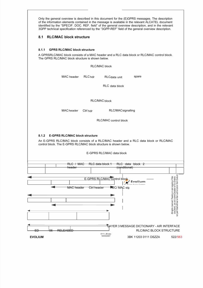
7/11/2019 1. Layer3 Air Interface Messages 0111_06
http://slidepdf.com/reader/full/1-layer3-air-interface-messages-011106 522/562
LAYER 3 MESSAGE DICTIONARY - AIR INTERFACE
ED 06 RELEASED RLC/MAC BLOCK STRUCTURE
EVOLIUM
0111_06.doc14/03/2007
3BK 11203 0111 DSZZA 522/ 563
Only the general overview is described in this document for the (E)GPRS messages. The descriptionof the information elements contained in the message is available in the relevant ALCATEL documentidentified by the “SPECIF. DOC. REF. field” of the general overview description, and in the relevant3GPP technical specification referenced by the “3GPP-REF” field of the general overview description.
8.1 RLC/MAC block structure
8.1.1 GPRS RLC/MAC block structure
A GPRSRLC/MAC block consists of a MAC header and a RLC data block or RLC/MAC control block.The GPRS RLC/MAC block structure is shown below.
RLC RLCMAC
RLC
RLC/MAC
RLC/MACMAC
RLC/MAC
RLC/MAC
spare
Ctrlheader
data unit
data block
block
signalling
hdr
control block
block
header
hdr
8.1.2 E-GPRS RLC/MAC block structure
An E-GPRS RLC/MAC block consists of a RLC/MAC header and a RLC data block or RLC/MACcontrol block. The E-GPRS RLC/MAC block structure is shown below.
MAC header Ctrl header RLC/ MAC sig
E-GPRS RLC/MAC control block
RLC / MACheader
RLC data block 1 RLC data block 2(conditional)
E-GPRS RLC/MAC data block

7/11/2019 1. Layer3 Air Interface Messages 0111_06
http://slidepdf.com/reader/full/1-layer3-air-interface-messages-011106 523/562
LAYER 3 MESSAGE DICTIONARY - AIR INTERFACE
ED 06 RELEASED RLC/MAC BLOCK STRUCTURE
EVOLIUM
0111_06.doc14/03/2007
3BK 11203 0111 DSZZA 523/ 563
8.1.3 RLC data blocks
8.1.3.1 GPRS RLC data blocks
The RLC data block consists of an RLC header, an RLC data unit, and spare bits. An RLC/MAC blockcontaining an RLC data block may be encoded using either channel coding scheme CS-1, CS-2, CS-3or CS-4. RLC/MAC blocks encoded using CS-1 do not contain spare bits. The size of the RLC data
block for each of the channel coding schemes is shown below.
Channel CodingScheme
RLC datablock size
without sparebits
Number of spare bits
RLC datablock size
(octets) (octets)
CS-1 22 0 22
CS-2 32 7 32 + 7/8
CS-3 38 3 38 + 3/8
CS-4 52 7 52 + 7/8
RLC data block size
8.1.3.1.1 Downlink GPRS RLC data blocks
The Downlink RLC data block together with its MAC header is formatted as shown below.
Bit8 7 6 5 4 3 2 1
PayloadType
RRBP S/P USF MAC header
PR TFI FBI Octet 1
BSN E Octet 2
Length indicator M E Octet 3 (optional)
.
.
.
.
.
.
Length indicator M E Octet M (optional)
Octet M+1
RLC data.
.
.Octet N-1Octet N
spare spare (if present)
See ref. [30] “FBS GPRS - Radio interface - RLC sublayer” for the semantic and the use of allinformation elements.

7/11/2019 1. Layer3 Air Interface Messages 0111_06
http://slidepdf.com/reader/full/1-layer3-air-interface-messages-011106 524/562
LAYER 3 MESSAGE DICTIONARY - AIR INTERFACE
ED 06 RELEASED RLC/MAC BLOCK STRUCTURE
EVOLIUM
0111_06.doc14/03/2007
3BK 11203 0111 DSZZA 524/ 563
8.1.3.1.2 Uplink GPRS RLC data blocks
The Uplink RLC data block together with its MAC header is formatted as shown below.
Bit8 7 6 5 4 3 2 1
PayloadType
Countdown Value SI R MAC header
spare TFI TI Octet 1BSN E Octet 2
Length indicator M E Octet 3 (optional)
.
.
.
.
.
.
Length indicator M E Octet M (optional)
Octet M+1 \ TLLI Octet M+2 }
(optional)Octet M+3 / Octet M+4 /
Octet M+5 (M+1 if noTLLI)
RLC data...Octet N-1Octet N
spare spare (if present)
See ref. [30] “FBS GPRS - Radio interface - RLC sublayer” for the semantic and the use of allinformation elements.
8.1.3.2 EGPRS RLC data blocks
The EGPRS RLC data block consists of a FBI (downlink) or TI (uplink) field and an E field followed byan EGPRS RLC data unit The EGPRS RLC data unit is a sequence of N2 octets that are numberedfrom 1 to N2. EGPRS RLC data blocks can be encoding using channel modulation and codingschemes MCS-1 to MCS-9.The size of the EGPRS RLC data unit for each of the channel coding schemes is shown in the tablebelow.

7/11/2019 1. Layer3 Air Interface Messages 0111_06
http://slidepdf.com/reader/full/1-layer3-air-interface-messages-011106 525/562
LAYER 3 MESSAGE DICTIONARY - AIR INTERFACE
ED 06 RELEASED RLC/MAC BLOCK STRUCTURE
EVOLIUM
0111_06.doc14/03/2007
3BK 11203 0111 DSZZA 525/ 563
Channel CodingScheme
EGPRS RLC data unit size (N2)(octets)
Family Comment
MCS-1 22 C
MCS-2 28 B
MCS-3 37 A
MCS-4 44 CMCS-5 56 B supported only in DL
MCS-6 74 A supported only in DL
MCS-7 2x56 B supported only in DL
MCS-8 2x68 A supported only in DL
MCS-9 2x74 A supported only in DL
8.1.3.2.1 Downlink EGPRS RLC data blocks
The EGPRS downlink RLC data blocks are formatted as follows :
Bit
2 1FBI E
Bit8 7 6 5 4 3 2 1
Length indicator E Octet 1 (note 1)(optional)
.
.
.
.
.
.
Length indicator E Octet M (optional)
Octet M+1
RLC data.
.
.Octet N2-1Octet N2
8.1.3.2.2 Downlink EGPRS RLC/MAC header
• Header type 1: header for MCS-7, MCS-8 and MCS-9 :The EGPRS combined downlink RLC/MAC header for MCS-7, MCS-8 and MCS-9 (header type 1) isformatted as described below.
Bit
8 7 6 5 4 3 2 1 OctetTFI RRBP ES/P USF 1
BSN1 PR TFI 2
BSN1 3
BSN2 BSN1
4
CPS BSN2 5
• Header type 2: header for MCS-6 and MCS-5 :The EGPRS combined downlink RLC/MAC header for MCS-5 and MCS-6 (header type 2) isformatted as follows :
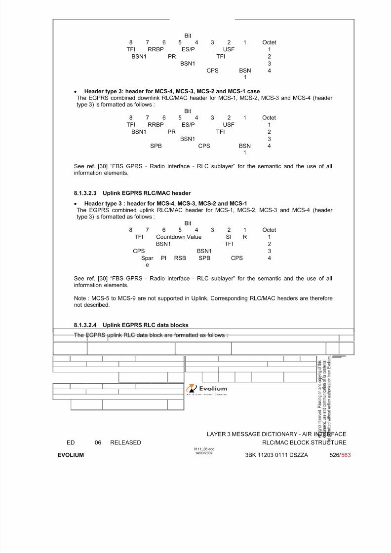
7/11/2019 1. Layer3 Air Interface Messages 0111_06
http://slidepdf.com/reader/full/1-layer3-air-interface-messages-011106 526/562
LAYER 3 MESSAGE DICTIONARY - AIR INTERFACE
ED 06 RELEASED RLC/MAC BLOCK STRUCTURE
EVOLIUM
0111_06.doc14/03/2007
3BK 11203 0111 DSZZA 526/ 563
Bit8 7 6 5 4 3 2 1 Octet
TFI RRBP ES/P USF 1
BSN1 PR TFI 2
BSN1 3
CPS BSN1
4
• Header type 3: header for MCS-4, MCS-3, MCS-2 and MCS-1 caseThe EGPRS combined downlink RLC/MAC header for MCS-1, MCS-2, MCS-3 and MCS-4 (header type 3) is formatted as follows :
Bit8 7 6 5 4 3 2 1 Octet
TFI RRBP ES/P USF 1
BSN1 PR TFI 2
BSN1 3
SPB CPS BSN1
4
See ref. [30] “FBS GPRS - Radio interface - RLC sublayer” for the semantic and the use of allinformation elements.
8.1.3.2.3 Uplink EGPRS RLC/MAC header
• Header type 3 : header for MCS-4, MCS-3, MCS-2 and MCS-1The EGPRS combined uplink RLC/MAC header for MCS-1, MCS-2, MCS-3 and MCS-4 (header type 3) is formatted as follows :
Bit8 7 6 5 4 3 2 1 Octet
TFI Countdown Value SI R 1
BSN1 TFI 2
CPS BSN1 3
Spar e
PI RSB SPB CPS 4
See ref. [30] “FBS GPRS - Radio interface - RLC sublayer” for the semantic and the use of allinformation elements.
Note : MCS-5 to MCS-9 are not supported in Uplink. Corresponding RLC/MAC headers are thereforenot described.
8.1.3.2.4 Uplink EGPRS RLC data blocks
The EGPRS uplink RLC data block are formatted as follows :

7/11/2019 1. Layer3 Air Interface Messages 0111_06
http://slidepdf.com/reader/full/1-layer3-air-interface-messages-011106 527/562
LAYER 3 MESSAGE DICTIONARY - AIR INTERFACE
ED 06 RELEASED RLC/MAC BLOCK STRUCTURE
EVOLIUM
0111_06.doc14/03/2007
3BK 11203 0111 DSZZA 527/ 563
Bit2 1
TI E
Bit8 7 6 5 4 3 2 1
Length indicator E Octet 1 (note 1)(optional)
.
.
.
.
.
.
Length indicator E Octet M (optional)
Octet M+1 \ TLLI Octet M+2 }
(optional)Octet M+3 / Octet M+4 /
PFI E Octet M + 5 /
Octet M+6
RLC data...Octet N2-1Octet N2
See ref. [30] “FBS GPRS - Radio interface - RLC sublayer” for the semantic and the use of allinformation elements.
8.1.4 (E)GPRS RLC/MAC control blocks
The (E)GPRS RLC/MAC control block consists of a control message contents field and in thedownlink direction an optional control header. (E)GPRS RLC/MAC control messages shall betransported within RLC/MAC control blocks. An RLC/MAC control block is always encoded using thecoding scheme CS-1.
8.1.4.1 Downlink (E)GPRS RLC/MAC control blocks
The Downlink RLC/MAC control block together with its MAC header is formatted as shown below.
Bit8 7 6 5 4 3 2 1
PayloadType RRBP S/P USF MAC header
Spare TFI D Octet 1 (optional)
Octet MControl Message Contents .
.
.Octet 21Octet 22
See ref. [31] “FBS GPRS - Radio interface - RLC sublayer” for the semantic and the use of allinformation elements.

7/11/2019 1. Layer3 Air Interface Messages 0111_06
http://slidepdf.com/reader/full/1-layer3-air-interface-messages-011106 528/562
LAYER 3 MESSAGE DICTIONARY - AIR INTERFACE
ED 06 RELEASED RLC/MAC BLOCK STRUCTURE
EVOLIUM
0111_06.doc14/03/2007
3BK 11203 0111 DSZZA 528/ 563
8.1.4.2 Uplink (E)GPRS RLC/MAC control blocks
The Downlink RLC/MAC control block together with its MAC header is formatted as shown below.
Bit8 7 6 5 4 3 2 1
PayloadType
spare R MAC header
Octet 1Octet 2Octet 3
Control Message Contents ...
Octet 21Octet 22
See ref. [30] “FBS GPRS - Radio interface - RLC sublayer” for the semantic and the use of allinformation elements.

7/11/2019 1. Layer3 Air Interface Messages 0111_06
http://slidepdf.com/reader/full/1-layer3-air-interface-messages-011106 529/562
LAYER 3 MESSAGE DICTIONARY - AIR INTERFACE
ED 06 RELEASED EGPRS PACKET DOWNLINK ACK/NACK
EVOLIUM
0111_06.doc14/03/2007
3BK 11203 0111 DSZZA 529/ 563
8.2 EGPRS PACKET DOWNLINK ACK/NACK
NAME EGPRS PACKET DOWNLINK ACK/NACK
INTERFACE RADIO ABIS A
CHANNEL/ USAGE
PACCH
3GPP-REF 44.060
FUNCTION This message is sent by the E-GPRS mobile station to the network on its PACCHto indicate the status of the downlink RLC data blocks received and to report thechannel quality of the downlink path.
The mobile station may optionally initiate an uplink TBF.
DIRECTION From: MS To: BTS
INFORMATION ELEMENT NAME TYPE COMMENT LENGTH(byte)
INFORMATIONELEMENT
LISTMAC header Control message contents
M V M V
122
IMPLEMENTATION MAXIMUM LENGTH 23
NORMAL SITUATION ABNORMAL SITUATION TIMER
FOLLOWINGEVENT
Receive window is updated. Notreceived blocks are
retransmitted. Downlink pathquality is assessed. Optionally an
uplink TBF is established.
SPECIFDOC. REF.
FBS GPRS - Radio interface - RRM sublayer - PCC (ref. [29])
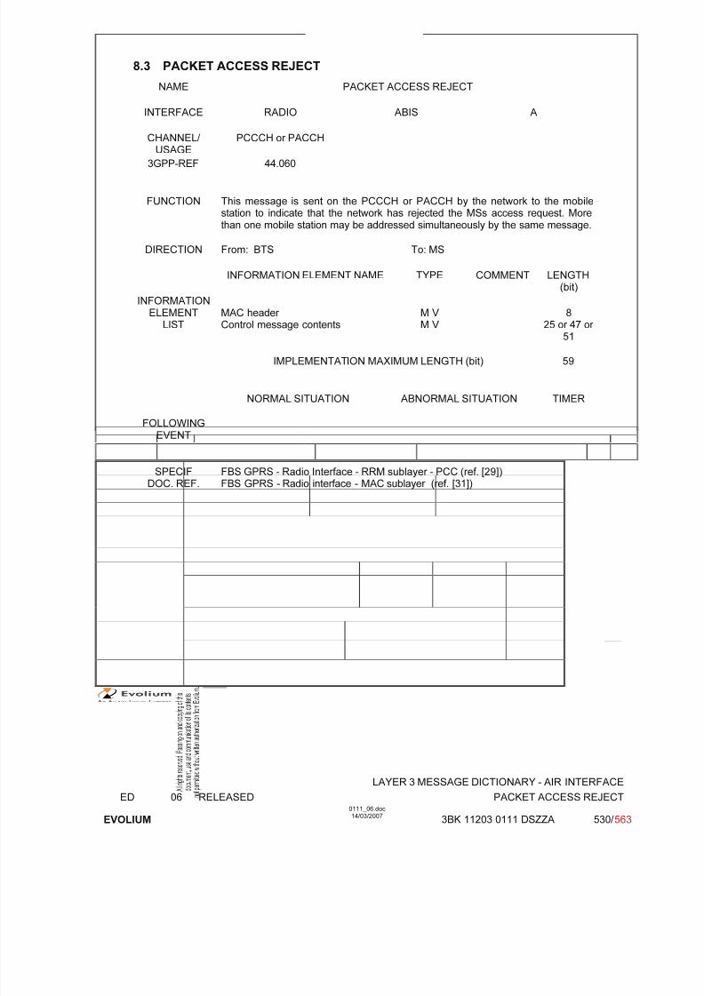
7/11/2019 1. Layer3 Air Interface Messages 0111_06
http://slidepdf.com/reader/full/1-layer3-air-interface-messages-011106 530/562
LAYER 3 MESSAGE DICTIONARY - AIR INTERFACE
ED 06 RELEASED PACKET ACCESS REJECT
EVOLIUM
0111_06.doc14/03/2007
3BK 11203 0111 DSZZA 530/ 563
8.3 PACKET ACCESS REJECT
NAME PACKET ACCESS REJECT
INTERFACE RADIO ABIS A
CHANNEL/
USAGE
PCCCH or PACCH
3GPP-REF 44.060
FUNCTION This message is sent on the PCCCH or PACCH by the network to the mobilestation to indicate that the network has rejected the MSs access request. Morethan one mobile station may be addressed simultaneously by the same message.
DIRECTION From: BTS To: MS
INFORMATION ELEMENT NAME TYPE COMMENT LENGTH(bit)
INFORMATIONELEMENT
LISTMAC header Control message contents
M V M V
825 or 47 or
51
IMPLEMENTATION MAXIMUM LENGTH (bit) 59
NORMAL SITUATION ABNORMAL SITUATION TIMER
FOLLOWINGEVENT
SPECIFDOC. REF.
FBS GPRS - Radio Interface - RRM sublayer - PCC (ref. [29])FBS GPRS - Radio interface - MAC sublayer (ref. [31])

7/11/2019 1. Layer3 Air Interface Messages 0111_06
http://slidepdf.com/reader/full/1-layer3-air-interface-messages-011106 531/562
LAYER 3 MESSAGE DICTIONARY - AIR INTERFACE
ED 06 RELEASED PACKET CELL CHANGE CONTINUE
EVOLIUM
0111_06.doc14/03/2007
3BK 11203 0111 DSZZA 531/ 563
8.4 PACKET CELL CHANGE CONTINUE
NAME PACKET CELL CHANGE CONTINUE
INTERFACE RADIO ABIS A
CHANNEL/ USAGE
PACCH
3GPP-REF 44.060
FUNCTION This message is sent by the network to the mobile station to command the mobilestation to continue the cell reselection procedure.
DIRECTION From: BTS To: MS
INFORMATION ELEMENT NAME TYPE COMMENT LENGTH(byte)
INFORMATIONELEMENT
LISTMAC header Control message contents
M V M V
122
IMPLEMENTATION MAXIMUM LENGTH 23
NORMAL SITUATION ABNORMAL SITUATION TIMER
FOLLOWINGEVENT
SPECIFDOC. REF.
FBS GPRS - Radio interface - RRM sublayer - PCC (ref. [29])

7/11/2019 1. Layer3 Air Interface Messages 0111_06
http://slidepdf.com/reader/full/1-layer3-air-interface-messages-011106 532/562
LAYER 3 MESSAGE DICTIONARY - AIR INTERFACE
ED 06 RELEASED PACKET CELL CHANGE FAILURE
EVOLIUM
0111_06.doc14/03/2007
3BK 11203 0111 DSZZA 532/ 563
8.5 PACKET CELL CHANGE FAILURE
NAME PACKET CELL CHANGE FAILURE
INTERFACE RADIO ABIS A
CHANNEL/
USAGE
PACCH
3GPP-REF 44.060
FUNCTION This message is sent by the mobile station to the network on its PACCH toindicate indicate that a commanded cell change order has failed.
DIRECTION From: MS To: BTS
INFORMATION ELEMENT NAME TYPE COMMENT LENGTH(byte)
INFORMATIONELEMENT
LISTMAC header Control message contents
M V M V
122
IMPLEMENTATION MAXIMUM LENGTH 23
NORMAL SITUATION ABNORMAL SITUATION TIMER
FOLLOWINGEVENT
SPECIFDOC. REF.
FBS GPRS - Radio interface - RRM sublayer - PCC (ref. [29])

7/11/2019 1. Layer3 Air Interface Messages 0111_06
http://slidepdf.com/reader/full/1-layer3-air-interface-messages-011106 533/562
LAYER 3 MESSAGE DICTIONARY - AIR INTERFACE
ED 06 RELEASED PACKET CELL CHANGE NOTIFICATION
EVOLIUM
0111_06.doc14/03/2007
3BK 11203 0111 DSZZA 533/ 563
8.6 PACKET CELL CHANGE NOTIFICATION
NAME PACKET CELL CHANGE NOTIFICATION
INTERFACE RADIO ABIS A
CHANNEL/ USAGE
PACCH
3GPP-REF 44.060
FUNCTION This message is sent by the mobile station to the network to inform the networkthat the cell re-selection criteria are now fulfilled and that the mobile station hasentered CCN mode
DIRECTION From: MS To: BTS
INFORMATION ELEMENT NAME TYPE COMMENT LENGTH(byte)
INFORMATIONELEMENT
LISTMAC header Control message contents
M V M V
122
IMPLEMENTATION MAXIMUM LENGTH 23
NORMAL SITUATION ABNORMAL SITUATION TIMER
FOLLOWING
EVENT
SPECIFDOC. REF.
FBS GPRS - Radio interface - RRM sublayer - PCC (ref. [29])

7/11/2019 1. Layer3 Air Interface Messages 0111_06
http://slidepdf.com/reader/full/1-layer3-air-interface-messages-011106 534/562
LAYER 3 MESSAGE DICTIONARY - AIR INTERFACE
ED 06 RELEASED PACKET CELL CHANGE ORDER
EVOLIUM
0111_06.doc14/03/2007
3BK 11203 0111 DSZZA 534/ 563
8.7 PACKET CELL CHANGE ORDER
NAME PACKET CELL CHANGE ORDER
INTERFACE RADIO ABIS A
CHANNEL/ USAGE
PACCH
3GPP-REF 44.060
FUNCTIONThis message is sent on the PACCH by the network to the mobile station tocommand the mobile station to leave the current cell and change to a new cell.
DIRECTION From: BTS To: MS
INFORMATION ELEMENT NAME TYPE COMMENT LENGTH(byte)
INFORMATIONELEMENT
LISTMAC header Control message contents
M V M V
122
IMPLEMENTATION MAXIMUM LENGTH 23
NORMAL SITUATION ABNORMAL SITUATION TIMER
FOLLOWINGEVENT
SPECIFDOC. REF.
FBS GPRS - Radio interface - RRM sublayer - PCC (ref. [29])

7/11/2019 1. Layer3 Air Interface Messages 0111_06
http://slidepdf.com/reader/full/1-layer3-air-interface-messages-011106 535/562
LAYER 3 MESSAGE DICTIONARY - AIR INTERFACE
ED 06 RELEASED PACKET CONTROL ACKNOWLEDGEMENT
EVOLIUM
0111_06.doc14/03/2007
3BK 11203 0111 DSZZA 535/ 563
8.8 PACKET CONTROL ACKNOWLEDGMENT
NAME PACKET CONTROL ACKNOWLEDGMENT
INTERFACE RADIO ABIS A
CHANNEL/
USAGE
PACCH
3GPP-REF 44.060
FUNCTION This message is sent on the PACCH by the mobile station to the network as ananswer to a polling request sent by the network in a previous downlink RLC/MACcontrol block through the RRBP mechanism.
The message is formatted as 4 identical access bursts. The access burst formatis 8 bits long (the 11 bits format is not implemented).
DIRECTION From: MS To: BTS
INFORMATION ELEMENT NAME TYPE COMMENT LENGTH(bit)
INFORMATIONELEMENT
LISTMessage_typeCTRL_ACK
M V M V
62
IMPLEMENTATION MAXIMUM LENGTH (bit) 8
NORMAL SITUATION ABNORMAL SITUATION TIMER
FOLLOWINGEVENT
The on-going procedure (e.g.TBF establishment) is continued.
The on-going procedure (e.g.TBF establishment) is stopped
and potentially restarted.
SPECIFDOC. REF.
FBS GPRS - Radio Interface - RRM sublayer - PCC (ref. [29])FBS GPRS - Radio interface - RLC sublayer (ref. [30])FBS GPRS - Radio interface - MAC sublayer (ref. [31])

7/11/2019 1. Layer3 Air Interface Messages 0111_06
http://slidepdf.com/reader/full/1-layer3-air-interface-messages-011106 536/562
LAYER 3 MESSAGE DICTIONARY - AIR INTERFACE
ED 06 RELEASED PACKET CHANNEL REQUEST
EVOLIUM
0111_06.doc14/03/2007
3BK 11203 0111 DSZZA 536/ 563
8.9 PACKET CHANNEL REQUEST
NAME PACKET CHANNEL REQUEST
INTERFACE RADIO ABIS A
CHANNEL/ USAGE PRACH
3GPP-REF 44.060
FUNCTION In a cell configured with a PBCCH channel, this message is sent by the mobilestation on the PRACH to perform an uplink access.
The message is 8 or 11 bits long.
DIRECTION From: MS To: BTS
INFORMATION ELEMENT NAME TYPE COMMENT LENGTH(bit)
INFORMATIONELEMENT
LISTSee 3GPP-REF.
IMPLEMENTATION MAXIMUM LENGTH (bit) 11
NORMAL SITUATION ABNORMAL SITUATION TIMER
FOLLOWINGEVENT
Establishment of an on-goingTBF or allocation of one uplink
radio block
SPECIFDOC. REF.
FBS GPRS - Radio Interface - RRM sublayer - PCC (ref. [29])FBS GPRS - Radio interface - MAC sublayer (ref. [31])

7/11/2019 1. Layer3 Air Interface Messages 0111_06
http://slidepdf.com/reader/full/1-layer3-air-interface-messages-011106 537/562
LAYER 3 MESSAGE DICTIONARY - AIR INTERFACE
ED 06 RELEASED PACKET DOWNLINK ACK/NACK
EVOLIUM
0111_06.doc14/03/2007
3BK 11203 0111 DSZZA 537/ 563
8.10 PACKET DOWNLINK ACK/NACK
NAME PACKET DOWNLINK ACK/NACK
INTERFACE RADIO ABIS A
CHANNEL/ USAGE PACCH
3GPP-REF 44.060
FUNCTION This message is sent by the mobile station to the network on its PACCH toindicate the status of the downlink RLC data blocks received and to report thechannel quality of the downlink path.
The mobile station may optionally initiate an uplink TBF.
DIRECTION From: MS To: BTS
INFORMATION ELEMENT NAME TYPE COMMENT LENGTH(byte)
INFORMATIONELEMENT
LISTMAC header Control message contents
M V M V
122
IMPLEMENTATION MAXIMUM LENGTH 23
NORMAL SITUATION ABNORMAL SITUATION TIMER
FOLLOWING
EVENT
Receive window is updated. Not
received blocks areretransmitted. Downlink path
quality is assessed. Optionally anuplink TBF is established.
SPECIFDOC. REF.
FBS GPRS - Radio interface - RLC sublayer (ref. [30])FBS GPRS - Radio interface - RRM sublayer - PCC (ref. [29])
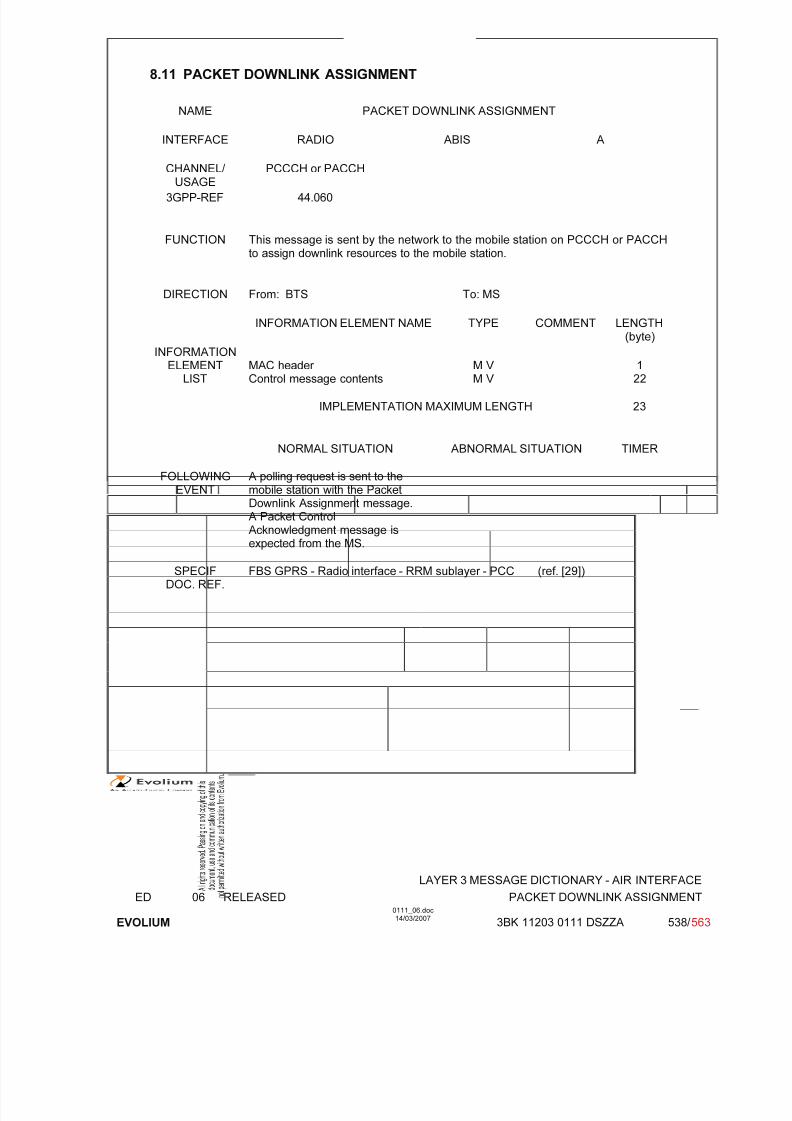
7/11/2019 1. Layer3 Air Interface Messages 0111_06
http://slidepdf.com/reader/full/1-layer3-air-interface-messages-011106 538/562
LAYER 3 MESSAGE DICTIONARY - AIR INTERFACE
ED 06 RELEASED PACKET DOWNLINK ASSIGNMENT
EVOLIUM
0111_06.doc14/03/2007
3BK 11203 0111 DSZZA 538/ 563
8.11 PACKET DOWNLINK ASSIGNMENT
NAME PACKET DOWNLINK ASSIGNMENT
INTERFACE RADIO ABIS A
CHANNEL/ USAGE PCCCH or PACCH
3GPP-REF 44.060
FUNCTION This message is sent by the network to the mobile station on PCCCH or PACCHto assign downlink resources to the mobile station.
DIRECTION From: BTS To: MS
INFORMATION ELEMENT NAME TYPE COMMENT LENGTH(byte)
INFORMATIONELEMENT
LISTMAC header Control message contents
M V M V
122
IMPLEMENTATION MAXIMUM LENGTH 23
NORMAL SITUATION ABNORMAL SITUATION TIMER
FOLLOWINGEVENT
A polling request is sent to themobile station with the PacketDownlink Assignment message.
A Packet ControlAcknowledgment message isexpected from the MS.
SPECIFDOC. REF.
FBS GPRS - Radio interface - RRM sublayer - PCC (ref. [29])

7/11/2019 1. Layer3 Air Interface Messages 0111_06
http://slidepdf.com/reader/full/1-layer3-air-interface-messages-011106 539/562
LAYER 3 MESSAGE DICTIONARY - AIR INTERFACE
ED 06 RELEASED PACKET DOWNLINK DUMMY CONTROL BLOCK
EVOLIUM
0111_06.doc14/03/2007
3BK 11203 0111 DSZZA 539/ 563
8.12 PACKET DOWNLINK DUMMY CONTROL BLOCK
NAME PACKET DOWNLINK DUMMY CONTROL BLOCK
INTERFACE RADIO ABIS A
CHANNEL/ USAGE PCCCH or PACCH
3GPP-REF 44.060
FUNCTION This message is sent by the network to the mobile station on PCCCH or PACCHas a fill message with the allocated USF for the corresponding uplink block incase there is no on-going downlink data transfer or in case of Ater desynchronization between the BTS and the MFS.
DIRECTION From: BTS To: MS
INFORMATION ELEMENT NAME TYPE COMMENT LENGTH(byte)
INFORMATIONELEMENT
LISTMAC header Control message contents
M V M V
122
IMPLEMENTATION MAXIMUM LENGTH 23
NORMAL SITUATION ABNORMAL SITUATION TIMER
FOLLOWINGEVENT
SPECIFDOC. REF.
FBS GPRS - Radio interface - MAC sublayer (ref. [31])
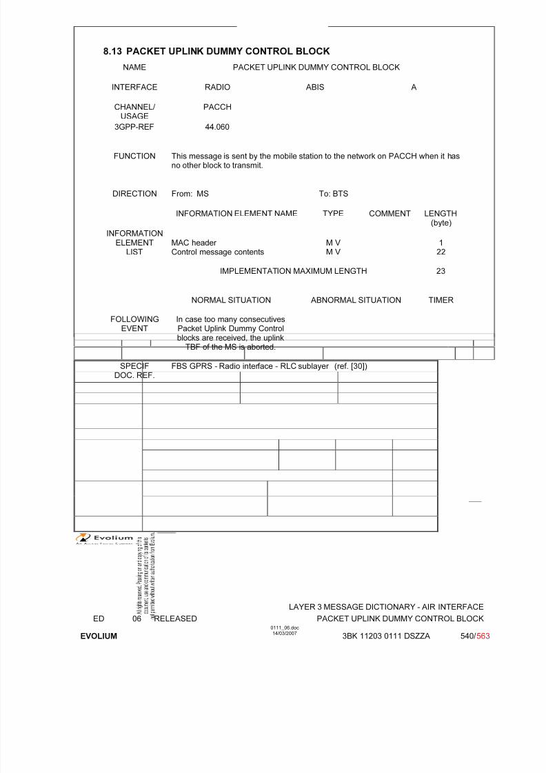
7/11/2019 1. Layer3 Air Interface Messages 0111_06
http://slidepdf.com/reader/full/1-layer3-air-interface-messages-011106 540/562
LAYER 3 MESSAGE DICTIONARY - AIR INTERFACE
ED 06 RELEASED PACKET UPLINK DUMMY CONTROL BLOCK
EVOLIUM
0111_06.doc14/03/2007
3BK 11203 0111 DSZZA 540/ 563
8.13 PACKET UPLINK DUMMY CONTROL BLOCK
NAME PACKET UPLINK DUMMY CONTROL BLOCK
INTERFACE RADIO ABIS A
CHANNEL/
USAGE
PACCH
3GPP-REF 44.060
FUNCTION This message is sent by the mobile station to the network on PACCH when it hasno other block to transmit.
DIRECTION From: MS To: BTS
INFORMATION ELEMENT NAME TYPE COMMENT LENGTH(byte)
INFORMATIONELEMENT
LISTMAC header Control message contents
M V M V
122
IMPLEMENTATION MAXIMUM LENGTH 23
NORMAL SITUATION ABNORMAL SITUATION TIMER
FOLLOWINGEVENT
In case too many consecutivesPacket Uplink Dummy Controlblocks are received, the uplink
TBF of the MS is aborted.
SPECIFDOC. REF.
FBS GPRS - Radio interface - RLC sublayer (ref. [30])
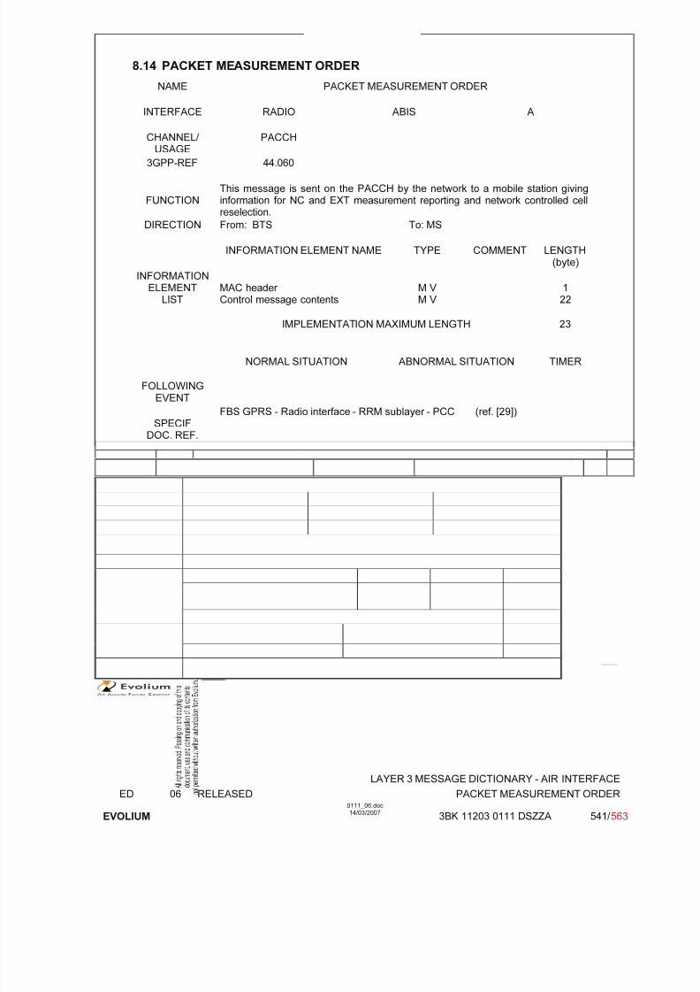
7/11/2019 1. Layer3 Air Interface Messages 0111_06
http://slidepdf.com/reader/full/1-layer3-air-interface-messages-011106 541/562
LAYER 3 MESSAGE DICTIONARY - AIR INTERFACE
ED 06 RELEASED PACKET MEASUREMENT ORDER
EVOLIUM
0111_06.doc14/03/2007
3BK 11203 0111 DSZZA 541/ 563
8.14 PACKET MEASUREMENT ORDER
NAME PACKET MEASUREMENT ORDER
INTERFACE RADIO ABIS A
CHANNEL/
USAGE
PACCH
3GPP-REF 44.060
FUNCTIONThis message is sent on the PACCH by the network to a mobile station givinginformation for NC and EXT measurement reporting and network controlled cellreselection.
DIRECTION From: BTS To: MS
INFORMATION ELEMENT NAME TYPE COMMENT LENGTH(byte)
INFORMATIONELEMENT
LISTMAC header Control message contents
M V M V
122
IMPLEMENTATION MAXIMUM LENGTH 23
NORMAL SITUATION ABNORMAL SITUATION TIMER
FOLLOWINGEVENT
SPECIFDOC. REF.
FBS GPRS - Radio interface - RRM sublayer - PCC (ref. [29])
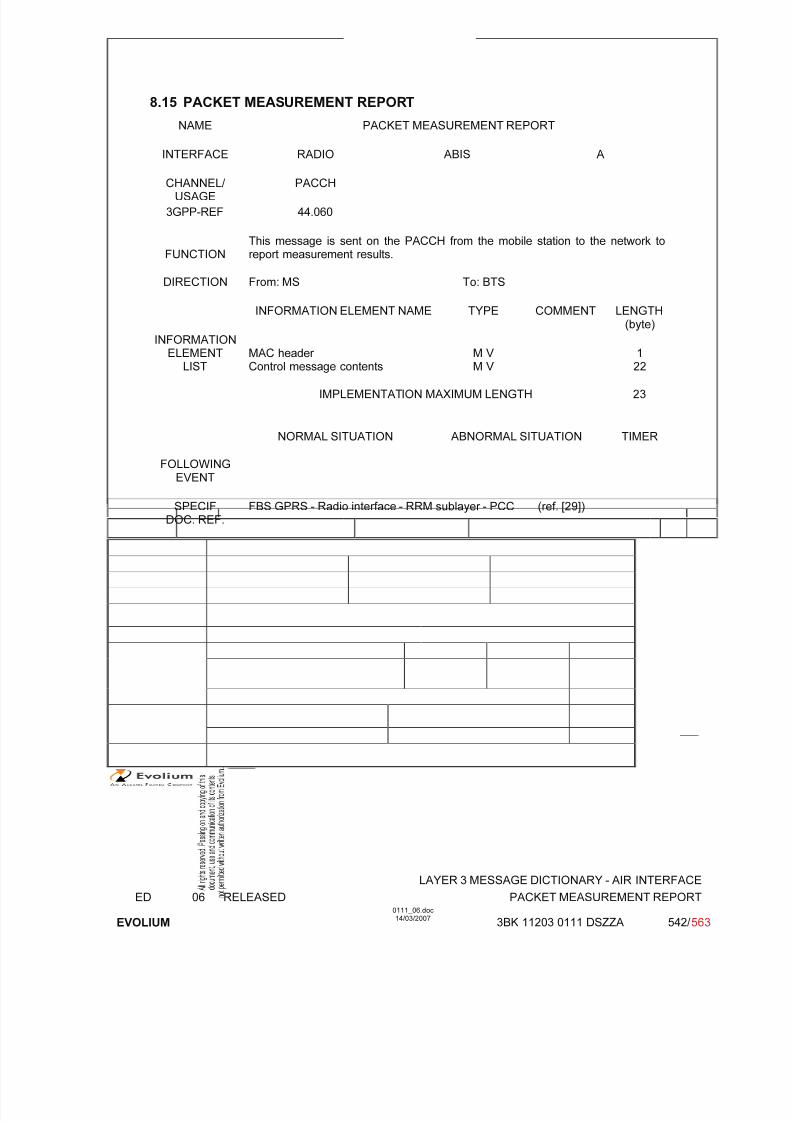
7/11/2019 1. Layer3 Air Interface Messages 0111_06
http://slidepdf.com/reader/full/1-layer3-air-interface-messages-011106 542/562
LAYER 3 MESSAGE DICTIONARY - AIR INTERFACE
ED 06 RELEASED PACKET MEASUREMENT REPORT
EVOLIUM
0111_06.doc14/03/2007
3BK 11203 0111 DSZZA 542/ 563
8.15 PACKET MEASUREMENT REPORT
NAME PACKET MEASUREMENT REPORT
INTERFACE RADIO ABIS A
CHANNEL/ USAGE
PACCH
3GPP-REF 44.060
FUNCTIONThis message is sent on the PACCH from the mobile station to the network toreport measurement results.
DIRECTION From: MS To: BTS
INFORMATION ELEMENT NAME TYPE COMMENT LENGTH(byte)
INFORMATIONELEMENTLIST
MAC header Control message contents
M V M V
122
IMPLEMENTATION MAXIMUM LENGTH 23
NORMAL SITUATION ABNORMAL SITUATION TIMER
FOLLOWINGEVENT
SPECIF
DOC. REF.
FBS GPRS - Radio interface - RRM sublayer - PCC (ref. [29])

7/11/2019 1. Layer3 Air Interface Messages 0111_06
http://slidepdf.com/reader/full/1-layer3-air-interface-messages-011106 543/562
LAYER 3 MESSAGE DICTIONARY - AIR INTERFACE
ED 06 RELEASED PACKET MOBILE TBF STATUS
EVOLIUM
0111_06.doc14/03/2007
3BK 11203 0111 DSZZA 543/ 563
8.16 PACKET MOBILE TBF STATUS
NAME PACKET MOBILE TBF STATUS
INTERFACE RADIO ABIS A
CHANNEL/ USAGE PACCH
3GPP-REF 44.060
FUNCTION This message is sent by the mobile station to the network on PACCH to indicatethat an erroneous message has been received related to either a downlink or anuplink TBF.
DIRECTION From: MS To: BTS
INFORMATION ELEMENT NAME TYPE COMMENT LENGTH(byte)
INFORMATIONELEMENT
LISTMAC header Control message contents
M V M V
122
IMPLEMENTATION MAXIMUM LENGTH 23
NORMAL SITUATION ABNORMAL SITUATION TIMER
FOLLOWINGEVENT
An error counter is incrementedin RLC layer.
SPECIFDOC. REF.
FBS GPRS - Radio interface - RLC sublayer (ref. [30])
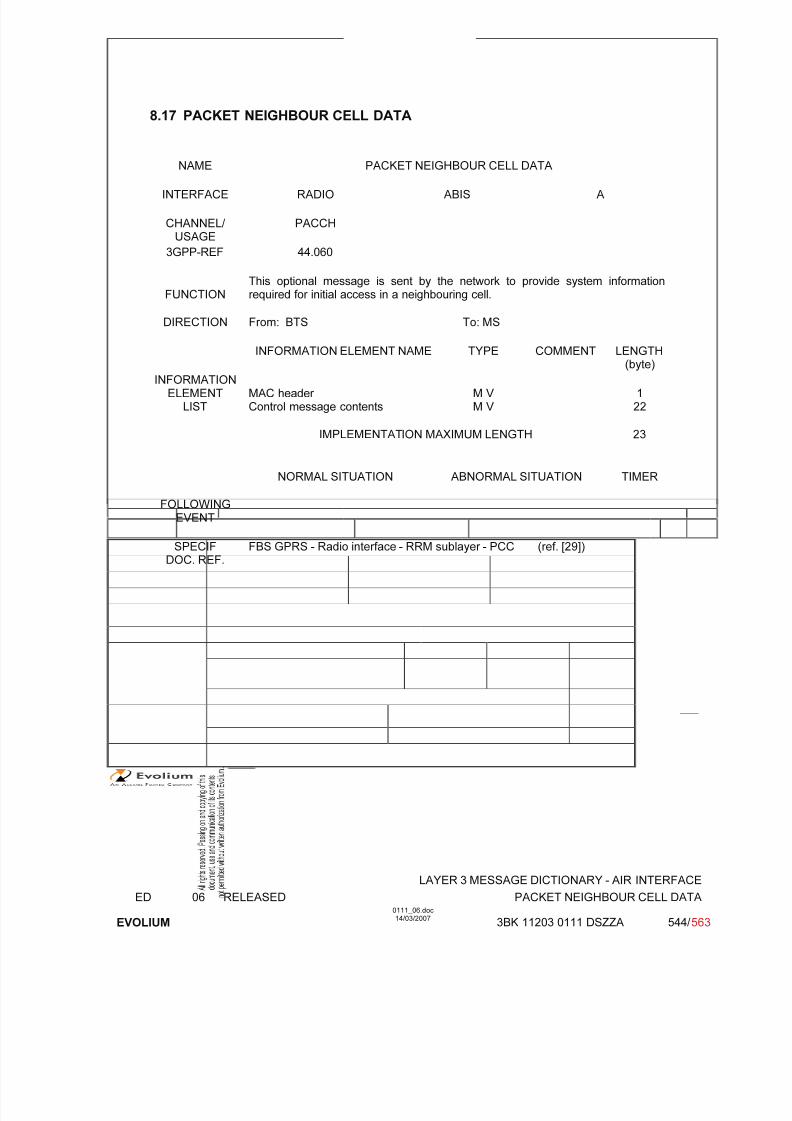
7/11/2019 1. Layer3 Air Interface Messages 0111_06
http://slidepdf.com/reader/full/1-layer3-air-interface-messages-011106 544/562
LAYER 3 MESSAGE DICTIONARY - AIR INTERFACE
ED 06 RELEASED PACKET NEIGHBOUR CELL DATA
EVOLIUM
0111_06.doc14/03/2007
3BK 11203 0111 DSZZA 544/ 563
8.17 PACKET NEIGHBOUR CELL DATA
NAME PACKET NEIGHBOUR CELL DATA
INTERFACE RADIO ABIS A
CHANNEL/ USAGE
PACCH
3GPP-REF 44.060
FUNCTIONThis optional message is sent by the network to provide system informationrequired for initial access in a neighbouring cell.
DIRECTION From: BTS To: MS
INFORMATION ELEMENT NAME TYPE COMMENT LENGTH(byte)
INFORMATIONELEMENT
LISTMAC header Control message contents
M V M V
122
IMPLEMENTATION MAXIMUM LENGTH 23
NORMAL SITUATION ABNORMAL SITUATION TIMER
FOLLOWING
EVENT
SPECIFDOC. REF.
FBS GPRS - Radio interface - RRM sublayer - PCC (ref. [29])
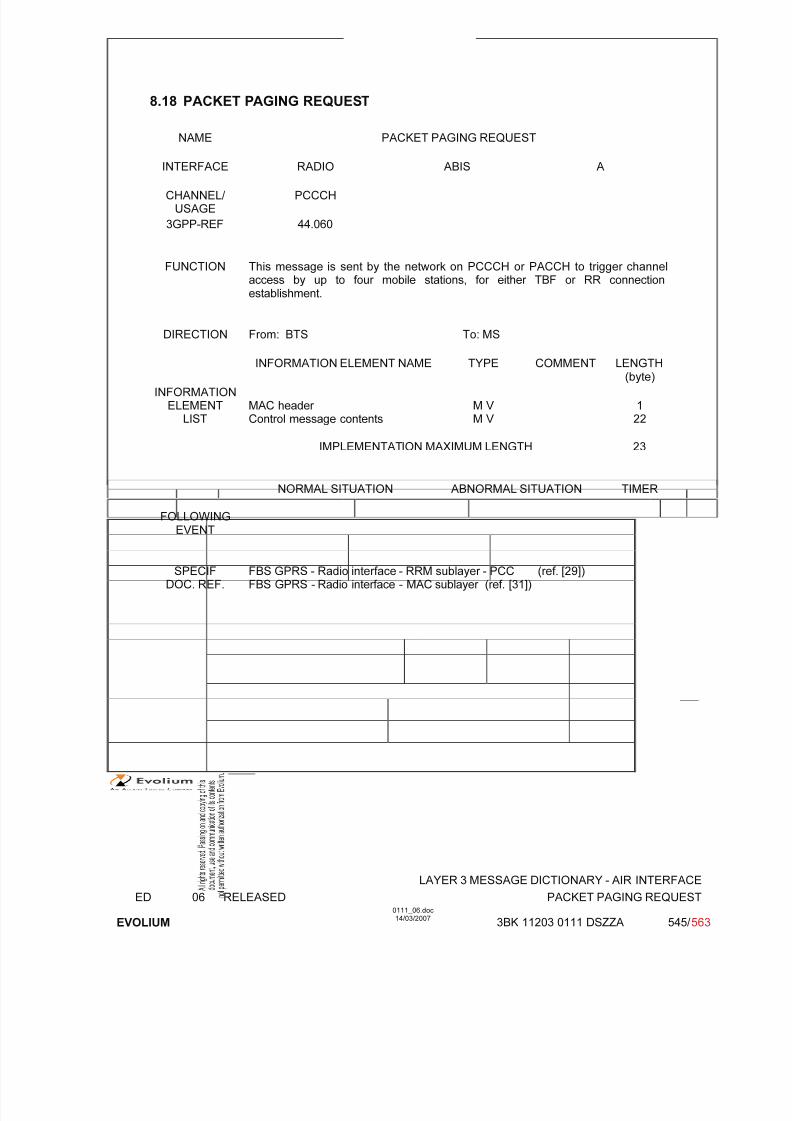
7/11/2019 1. Layer3 Air Interface Messages 0111_06
http://slidepdf.com/reader/full/1-layer3-air-interface-messages-011106 545/562
LAYER 3 MESSAGE DICTIONARY - AIR INTERFACE
ED 06 RELEASED PACKET PAGING REQUEST
EVOLIUM
0111_06.doc14/03/2007
3BK 11203 0111 DSZZA 545/ 563
8.18 PACKET PAGING REQUEST
NAME PACKET PAGING REQUEST
INTERFACE RADIO ABIS A
CHANNEL/ USAGE
PCCCH
3GPP-REF 44.060
FUNCTION This message is sent by the network on PCCCH or PACCH to trigger channelaccess by up to four mobile stations, for either TBF or RR connectionestablishment.
DIRECTION From: BTS To: MS
INFORMATION ELEMENT NAME TYPE COMMENT LENGTH(byte)
INFORMATIONELEMENT
LISTMAC header Control message contents
M V M V
122
IMPLEMENTATION MAXIMUM LENGTH 23
NORMAL SITUATION ABNORMAL SITUATION TIMER
FOLLOWINGEVENT
SPECIFDOC. REF.
FBS GPRS - Radio interface - RRM sublayer - PCC (ref. [29])FBS GPRS - Radio interface - MAC sublayer (ref. [31])

7/11/2019 1. Layer3 Air Interface Messages 0111_06
http://slidepdf.com/reader/full/1-layer3-air-interface-messages-011106 546/562
LAYER 3 MESSAGE DICTIONARY - AIR INTERFACE
ED 06 RELEASED PACKET PDCH RELEASE
EVOLIUM
0111_06.doc14/03/2007
3BK 11203 0111 DSZZA 546/ 563
8.19 PACKET PDCH RELEASE
NAME PACKET PDCH RELEASE
INTERFACE RADIO ABIS A
CHANNEL/ USAGE PACCH
3GPP-REF 44.060
FUNCTION This message is sent by the network on PACCH to notify all mobile stationslistening to that PDCH that one or more PDCHs will be immediatly released andbecome unavailable for packet data traffic.
DIRECTION From: BTS To: MS
INFORMATION ELEMENT NAME TYPE COMMENT LENGTH(byte)
INFORMATIONELEMENT
LISTMAC header Control message contents
M V M V
122
IMPLEMENTATION MAXIMUM LENGTH 23
NORMAL SITUATION ABNORMAL SITUATION TIMER
FOLLOWINGEVENT
SPECIFDOC. REF.
FBS GPRS - Radio interface - RRM sublayer - PCC (ref. [29])
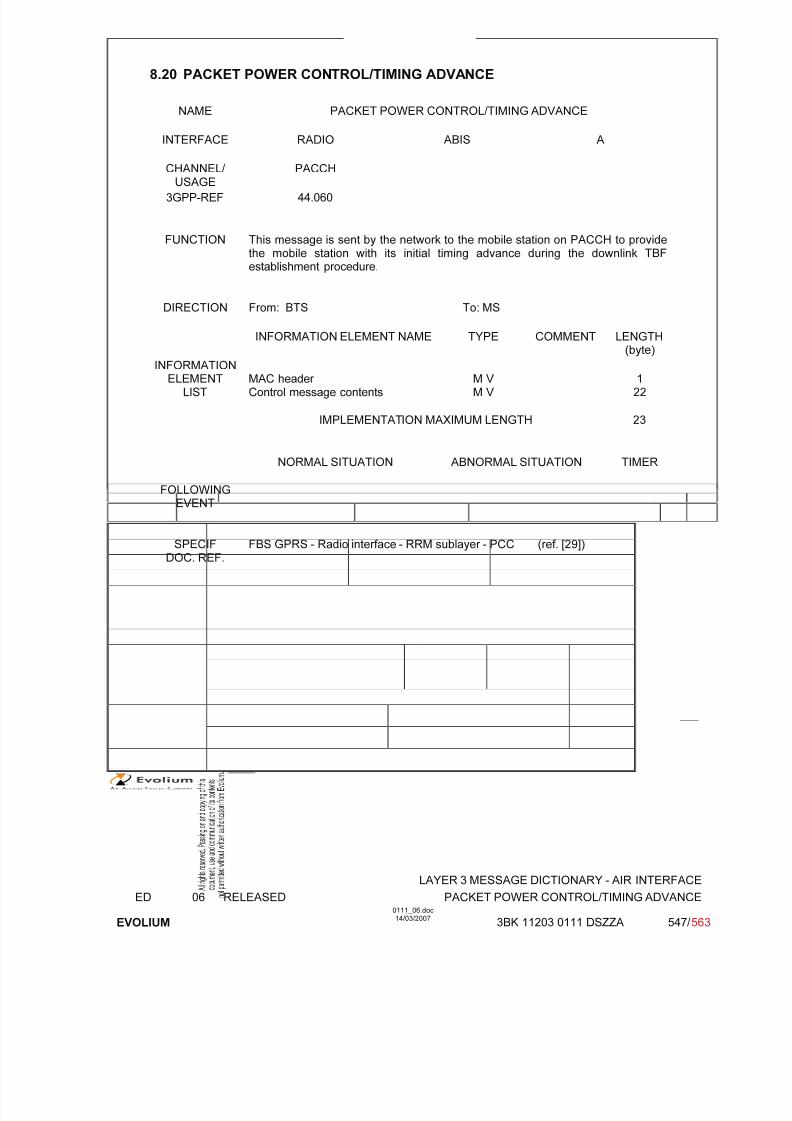
7/11/2019 1. Layer3 Air Interface Messages 0111_06
http://slidepdf.com/reader/full/1-layer3-air-interface-messages-011106 547/562
LAYER 3 MESSAGE DICTIONARY - AIR INTERFACE
ED 06 RELEASED PACKET POWER CONTROL/TIMING ADVANCE
EVOLIUM
0111_06.doc14/03/2007
3BK 11203 0111 DSZZA 547/ 563
8.20 PACKET POWER CONTROL/TIMING ADVANCE
NAME PACKET POWER CONTROL/TIMING ADVANCE
INTERFACE RADIO ABIS A
CHANNEL/ USAGE PACCH
3GPP-REF 44.060
FUNCTION This message is sent by the network to the mobile station on PACCH to providethe mobile station with its initial timing advance during the downlink TBFestablishment procedure.
DIRECTION From: BTS To: MS
INFORMATION ELEMENT NAME TYPE COMMENT LENGTH(byte)
INFORMATIONELEMENT
LISTMAC header Control message contents
M V M V
122
IMPLEMENTATION MAXIMUM LENGTH 23
NORMAL SITUATION ABNORMAL SITUATION TIMER
FOLLOWINGEVENT
SPECIFDOC. REF.
FBS GPRS - Radio interface - RRM sublayer - PCC (ref. [29])
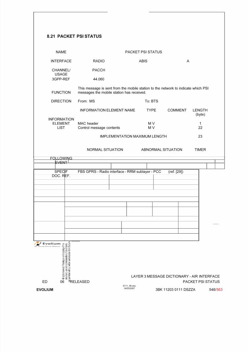
7/11/2019 1. Layer3 Air Interface Messages 0111_06
http://slidepdf.com/reader/full/1-layer3-air-interface-messages-011106 548/562
LAYER 3 MESSAGE DICTIONARY - AIR INTERFACE
ED 06 RELEASED PACKET PSI STATUS
EVOLIUM
0111_06.doc14/03/2007
3BK 11203 0111 DSZZA 548/ 563
8.21 PACKET PSI STATUS
NAME PACKET PSI STATUS
INTERFACE RADIO ABIS A
CHANNEL/ USAGE
PACCH
3GPP-REF 44.060
FUNCTIONThis message is sent from the mobile station to the network to indicate which PSImessages the mobile station has received.
DIRECTION From: MS To: BTS
INFORMATION ELEMENT NAME TYPE COMMENT LENGTH(byte)
INFORMATIONELEMENT
LISTMAC header Control message contents
M V M V
122
IMPLEMENTATION MAXIMUM LENGTH 23
NORMAL SITUATION ABNORMAL SITUATION TIMER
FOLLOWING
EVENT
SPECIFDOC. REF.
FBS GPRS - Radio interface - RRM sublayer - PCC (ref. [29])

7/11/2019 1. Layer3 Air Interface Messages 0111_06
http://slidepdf.com/reader/full/1-layer3-air-interface-messages-011106 549/562
LAYER 3 MESSAGE DICTIONARY - AIR INTERFACE
ED 06 RELEASED PACKET RESOURCE REQUEST
EVOLIUM
0111_06.doc14/03/2007
3BK 11203 0111 DSZZA 549/ 563
8.22 PACKET RESOURCE REQUEST
NAME PACKET RESOURCE REQUEST
INTERFACE RADIO ABIS A
CHANNEL/ USAGE PACCH
3GPP-REF 44.060
FUNCTION This message is sent by the mobile station to the network on PACCH to requestthe establishment of an uplink TBF (2 phase access) or to request a change inthe uplink allocated resources.
DIRECTION From: MS To: BTS
INFORMATION ELEMENT NAME TYPE COMMENT LENGTH(byte)
INFORMATIONELEMENT
LISTMAC header Control message contents
M V M V
122
IMPLEMENTATION MAXIMUM LENGTH 23
NORMAL SITUATION ABNORMAL SITUATION TIMER
FOLLOWINGEVENT
An uplink TBF is established incase of a 2 phase access.
SPECIFDOC. REF.
FBS GPRS - Radio interface - RRM sublayer - PCC (ref. [29])
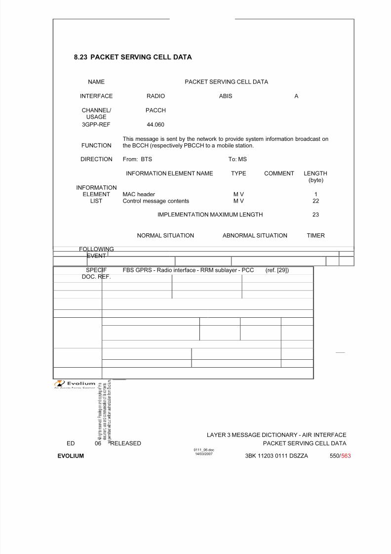
7/11/2019 1. Layer3 Air Interface Messages 0111_06
http://slidepdf.com/reader/full/1-layer3-air-interface-messages-011106 550/562
LAYER 3 MESSAGE DICTIONARY - AIR INTERFACE
ED 06 RELEASED PACKET SERVING CELL DATA
EVOLIUM
0111_06.doc14/03/2007
3BK 11203 0111 DSZZA 550/ 563
8.23 PACKET SERVING CELL DATA
NAME PACKET SERVING CELL DATA
INTERFACE RADIO ABIS A
CHANNEL/ USAGE
PACCH
3GPP-REF 44.060
FUNCTIONThis message is sent by the network to provide system information broadcast onthe BCCH (respectively PBCCH to a mobile station.
DIRECTION From: BTS To: MS
INFORMATION ELEMENT NAME TYPE COMMENT LENGTH(byte)
INFORMATIONELEMENT
LISTMAC header Control message contents
M V M V
122
IMPLEMENTATION MAXIMUM LENGTH 23
NORMAL SITUATION ABNORMAL SITUATION TIMER
FOLLOWING
EVENT
SPECIFDOC. REF.
FBS GPRS - Radio interface - RRM sublayer - PCC (ref. [29])
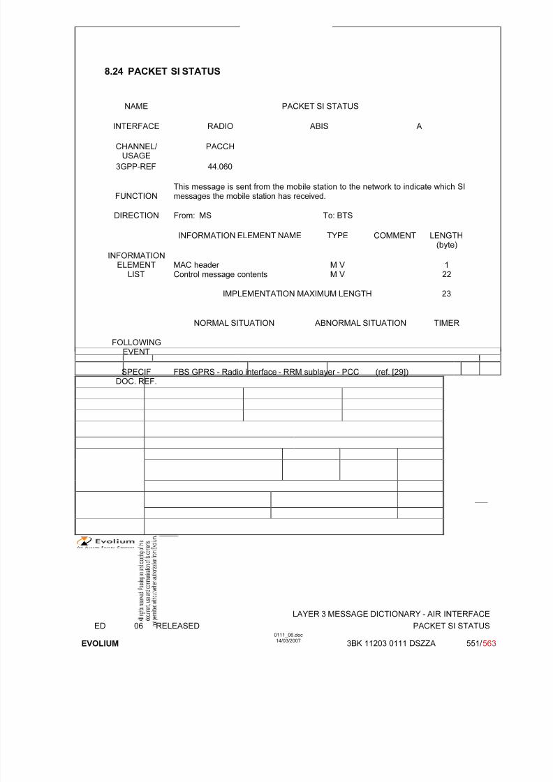
7/11/2019 1. Layer3 Air Interface Messages 0111_06
http://slidepdf.com/reader/full/1-layer3-air-interface-messages-011106 551/562
LAYER 3 MESSAGE DICTIONARY - AIR INTERFACE
ED 06 RELEASED PACKET SI STATUS
EVOLIUM
0111_06.doc14/03/2007
3BK 11203 0111 DSZZA 551/ 563
8.24 PACKET SI STATUS
NAME PACKET SI STATUS
INTERFACE RADIO ABIS A
CHANNEL/ USAGE
PACCH
3GPP-REF 44.060
FUNCTIONThis message is sent from the mobile station to the network to indicate which SImessages the mobile station has received.
DIRECTION From: MS To: BTS
INFORMATION ELEMENT NAME TYPE COMMENT LENGTH(byte)
INFORMATIONELEMENT
LISTMAC header Control message contents
M V M V
122
IMPLEMENTATION MAXIMUM LENGTH 23
NORMAL SITUATION ABNORMAL SITUATION TIMER
FOLLOWINGEVENT
SPECIFDOC. REF.
FBS GPRS - Radio interface - RRM sublayer - PCC (ref. [29])

7/11/2019 1. Layer3 Air Interface Messages 0111_06
http://slidepdf.com/reader/full/1-layer3-air-interface-messages-011106 552/562
LAYER 3 MESSAGE DICTIONARY - AIR INTERFACE
ED 06 RELEASED PACKET SYSTEM INFORMATION TYPE 1
EVOLIUM
0111_06.doc14/03/2007
3BK 11203 0111 DSZZA 552/ 563
8.25 PACKET SYSTEM INFORMATION TYPE 1
NAME PACKET SYSTEM INFORMATION TYPE 1
INTERFACE RADIO ABIS A
CHANNEL/ USAGE PBCCH or PACCH
3GPP-REF 44.060
FUNCTION This message is sent by the network on PBCCH giving information for cellselection, for control of the PRACH, for description of the control channel, and for power control.In case of a cell configured with PBCCH, the message is also sent periodically onPACCH to provide MS in packet transfer mode with the state of the packetsystem informations.
DIRECTION From: BTS To: MS
INFORMATION ELEMENT NAME TYPE COMMENT LENGTH(byte)
INFORMATIONELEMENT
LISTMAC header Control message contents
M V M V
122
IMPLEMENTATION MAXIMUM LENGTH 23
NORMAL SITUATION ABNORMAL SITUATION TIMER
FOLLOWINGEVENT
SPECIFDOC. REF.
FBS GPRS - Radio interface - RRM sublayer - PRH (ref. [34])

7/11/2019 1. Layer3 Air Interface Messages 0111_06
http://slidepdf.com/reader/full/1-layer3-air-interface-messages-011106 553/562
LAYER 3 MESSAGE DICTIONARY - AIR INTERFACE
ED 06 RELEASED PACKET SYSTEM INFORMATION TYPE 2
EVOLIUM
0111_06.doc14/03/2007
3BK 11203 0111 DSZZA 553/ 563
8.26 PACKET SYSTEM INFORMATION TYPE 2
NAME PACKET SYSTEM INFORMATION TYPE 2
INTERFACE RADIO ABIS A
CHANNEL/ USAGE PBCCH
3GPP-REF 44.060
FUNCTION This message is sent by the network on PBCCH giving information of referencefrequency list, cell allocation, GPRS mobile allocation and PCCCH description.
DIRECTION From: BTS To: MS
INFORMATION ELEMENT NAME TYPE COMMENT LENGTH(byte)
INFORMATIONELEMENT
LISTMAC header Control message contents
M V M V
122
IMPLEMENTATION MAXIMUM LENGTH 23
NORMAL SITUATION ABNORMAL SITUATION TIMER
FOLLOWINGEVENT
SPECIFDOC. REF.
FBS GPRS - Radio interface - RRM sublayer - PRH (ref. [34])
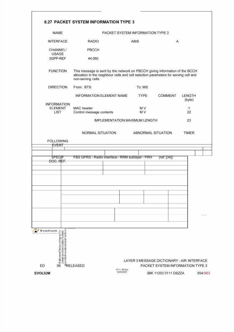
7/11/2019 1. Layer3 Air Interface Messages 0111_06
http://slidepdf.com/reader/full/1-layer3-air-interface-messages-011106 554/562
LAYER 3 MESSAGE DICTIONARY - AIR INTERFACE
ED 06 RELEASED PACKET SYSTEM INFORMATION TYPE 3
EVOLIUM
0111_06.doc14/03/2007
3BK 11203 0111 DSZZA 554/ 563
8.27 PACKET SYSTEM INFORMATION TYPE 3
NAME PACKET SYSTEM INFORMATION TYPE 3
INTERFACE RADIO ABIS A
CHANNEL/ USAGE PBCCH
3GPP-REF 44.060
FUNCTION This message is sent by the network on PBCCH giving information of the BCCHallocation in the neighbour cells and cell selection parameters for serving cell andnon-serving cells.
DIRECTION From: BTS To: MS
INFORMATION ELEMENT NAME TYPE COMMENT LENGTH(byte)
INFORMATIONELEMENT
LISTMAC header Control message contents
M V M V
122
IMPLEMENTATION MAXIMUM LENGTH 23
NORMAL SITUATION ABNORMAL SITUATION TIMER
FOLLOWINGEVENT
SPECIFDOC. REF.
FBS GPRS - Radio interface - RRM sublayer - PRH (ref. [34])
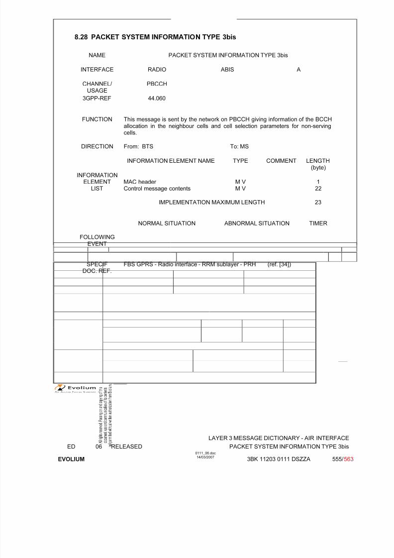
7/11/2019 1. Layer3 Air Interface Messages 0111_06
http://slidepdf.com/reader/full/1-layer3-air-interface-messages-011106 555/562
LAYER 3 MESSAGE DICTIONARY - AIR INTERFACE
ED 06 RELEASED PACKET SYSTEM INFORMATION TYPE 3bis
EVOLIUM
0111_06.doc14/03/2007
3BK 11203 0111 DSZZA 555/ 563
8.28 PACKET SYSTEM INFORMATION TYPE 3bis
NAME PACKET SYSTEM INFORMATION TYPE 3bis
INTERFACE RADIO ABIS A
CHANNEL/ USAGE PBCCH
3GPP-REF 44.060
FUNCTION This message is sent by the network on PBCCH giving information of the BCCHallocation in the neighbour cells and cell selection parameters for non-servingcells.
DIRECTION From: BTS To: MS
INFORMATION ELEMENT NAME TYPE COMMENT LENGTH(byte)
INFORMATIONELEMENT
LISTMAC header Control message contents
M V M V
122
IMPLEMENTATION MAXIMUM LENGTH 23
NORMAL SITUATION ABNORMAL SITUATION TIMER
FOLLOWINGEVENT
SPECIFDOC. REF.
FBS GPRS - Radio interface - RRM sublayer - PRH (ref. [34])
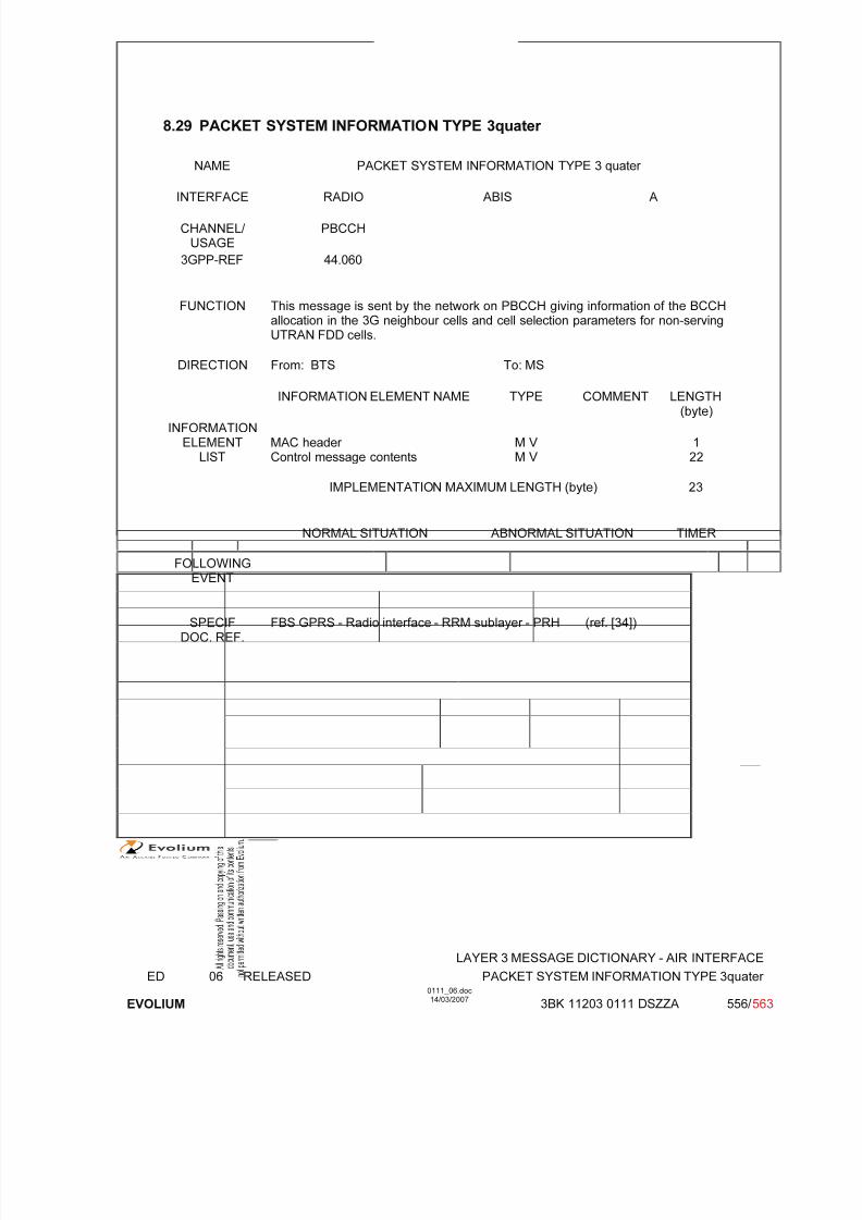
7/11/2019 1. Layer3 Air Interface Messages 0111_06
http://slidepdf.com/reader/full/1-layer3-air-interface-messages-011106 556/562
LAYER 3 MESSAGE DICTIONARY - AIR INTERFACE
ED 06 RELEASED PACKET SYSTEM INFORMATION TYPE 3quater
EVOLIUM
0111_06.doc14/03/2007
3BK 11203 0111 DSZZA 556/ 563
8.29 PACKET SYSTEM INFORMATION TYPE 3quater
NAME PACKET SYSTEM INFORMATION TYPE 3 quater
INTERFACE RADIO ABIS A
CHANNEL/ USAGE
PBCCH
3GPP-REF 44.060
FUNCTION This message is sent by the network on PBCCH giving information of the BCCHallocation in the 3G neighbour cells and cell selection parameters for non-servingUTRAN FDD cells.
DIRECTION From: BTS To: MS
INFORMATION ELEMENT NAME TYPE COMMENT LENGTH(byte)
INFORMATIONELEMENT
LISTMAC header Control message contents
M V M V
122
IMPLEMENTATION MAXIMUM LENGTH (byte) 23
NORMAL SITUATION ABNORMAL SITUATION TIMER
FOLLOWINGEVENT
SPECIFDOC. REF.
FBS GPRS - Radio interface - RRM sublayer - PRH (ref. [34])

7/11/2019 1. Layer3 Air Interface Messages 0111_06
http://slidepdf.com/reader/full/1-layer3-air-interface-messages-011106 557/562
LAYER 3 MESSAGE DICTIONARY - AIR INTERFACE
ED 06 RELEASED PACKET SYSTEM INFORMATION TYPE 8
EVOLIUM
0111_06.doc14/03/2007
3BK 11203 0111 DSZZA 557/ 563
8.30 PACKET SYSTEM INFORMATION TYPE 8
NAME PACKET SYSTEM INFORMATION TYPE 8
INTERFACE RADIO ABIS A
CHANNEL/ USAGE PBCCH and PACCH
3GPP-REF 44.060
FUNCTION This message is optionally sent by the network giving information about CellBroadcast Channel configuration.
DIRECTION From: BTS To: MS
INFORMATION ELEMENT NAME TYPE COMMENT LENGTH(byte)
INFORMATIONELEMENT
LISTMAC header Control message contents
M V M V
122
IMPLEMENTATION MAXIMUM LENGTH 23
NORMAL SITUATION ABNORMAL SITUATION TIMER
FOLLOWINGEVENT
SPECIFDOC. REF.
FBS GPRS - Radio interface - RRM sublayer - PRH (ref. [34])

7/11/2019 1. Layer3 Air Interface Messages 0111_06
http://slidepdf.com/reader/full/1-layer3-air-interface-messages-011106 558/562
LAYER 3 MESSAGE DICTIONARY - AIR INTERFACE
ED 06 RELEASED PACKET SYSTEM INFORMATION TYPE 13
EVOLIUM
0111_06.doc14/03/2007
3BK 11203 0111 DSZZA 558/ 563
8.31 PACKET SYSTEM INFORMATION TYPE 13
NAME PACKET SYSTEM INFORMATION TYPE 13
INTERFACE RADIO ABIS A
CHANNEL/ USAGE PACCH
3GPP-REF 44.060
FUNCTION In a cell without PBCCH, this message is sent by the network on PACCH toprovide mobile stations listening to the PDCH with GPRS cell specific access-related informations and with the status of the system informations.
DIRECTION From: BTS To: MS
INFORMATION ELEMENT NAME TYPE COMMENT LENGTH(byte)
INFORMATIONELEMENT
LISTMAC header Control message contents
M V M V
122
IMPLEMENTATION MAXIMUM LENGTH 23
NORMAL SITUATION ABNORMAL SITUATION TIMER
FOLLOWINGEVENT
SPECIFDOC. REF.
FBS GPRS - Radio interface - RRM sublayer - PRH (ref. [34])
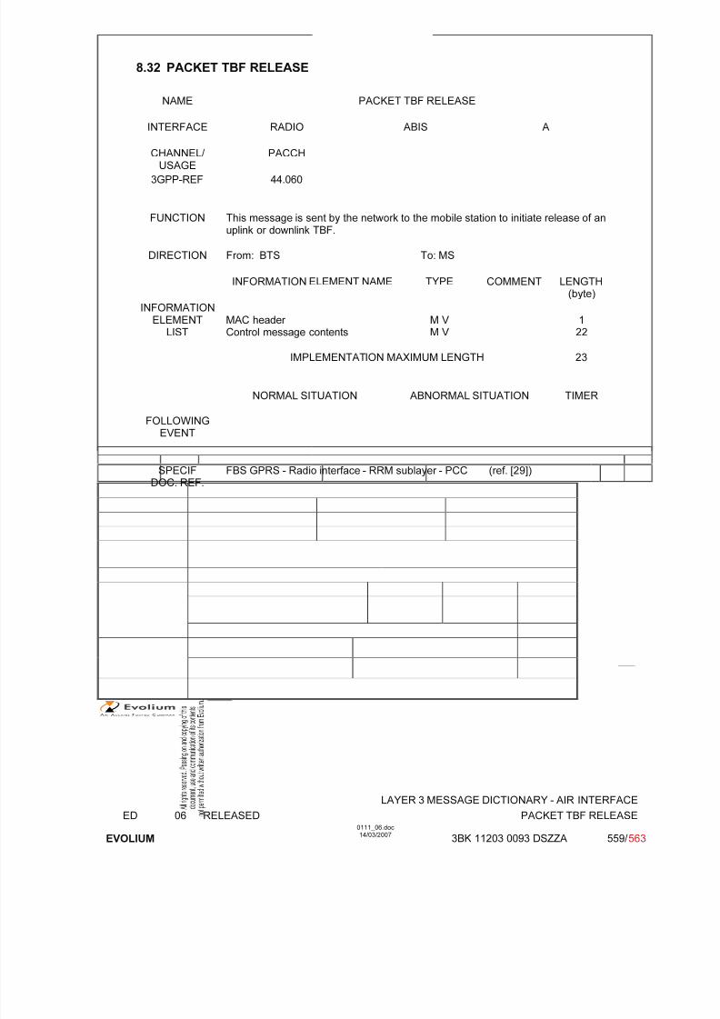
7/11/2019 1. Layer3 Air Interface Messages 0111_06
http://slidepdf.com/reader/full/1-layer3-air-interface-messages-011106 559/562
LAYER 3 MESSAGE DICTIONARY - AIR INTERFACE
ED 06 RELEASED PACKET TBF RELEASE
EVOLIUM
0111_06.doc14/03/2007
3BK 11203 0093 DSZZA 559/ 563
8.32 PACKET TBF RELEASE
NAME PACKET TBF RELEASE
INTERFACE RADIO ABIS A
CHANNEL/ USAGE PACCH
3GPP-REF 44.060
FUNCTION This message is sent by the network to the mobile station to initiate release of anuplink or downlink TBF.
DIRECTION From: BTS To: MS
INFORMATION ELEMENT NAME TYPE COMMENT LENGTH(byte)
INFORMATIONELEMENT
LISTMAC header Control message contents
M V M V
122
IMPLEMENTATION MAXIMUM LENGTH 23
NORMAL SITUATION ABNORMAL SITUATION TIMER
FOLLOWINGEVENT
SPECIFDOC. REF.
FBS GPRS - Radio interface - RRM sublayer - PCC (ref. [29])

7/11/2019 1. Layer3 Air Interface Messages 0111_06
http://slidepdf.com/reader/full/1-layer3-air-interface-messages-011106 560/562
LAYER 3 MESSAGE DICTIONARY - AIR INTERFACE
ED 06 RELEASED PACKET TIMESLOT RECONFIGURE
EVOLIUM
0111_06.doc14/03/2007
3BK 11203 0111 DSZZA 560/ 563
8.33 PACKET TIMESLOT RECONFIGURE
NAME PACKET TIMESLOT RECONFIGURE
INTERFACE RADIO ABIS A
CHANNEL/ USAGE PACCH
3GPP-REF 44.060
FUNCTION This message is sent on the PACCH by the network to the mobile station toassign uplink and downlink resources.
DIRECTION From: BTS To: MS
INFORMATION ELEMENT NAME TYPE COMMENT LENGTH(byte)
INFORMATIONELEMENT
LISTMAC header Control message contents
M V M V
122
IMPLEMENTATION MAXIMUM LENGTH 23
NORMAL SITUATION ABNORMAL SITUATION TIMER
FOLLOWINGEVENT
SPECIFDOC. REF.
FBS GPRS - Radio interface - RLC sublayer (ref. [30])
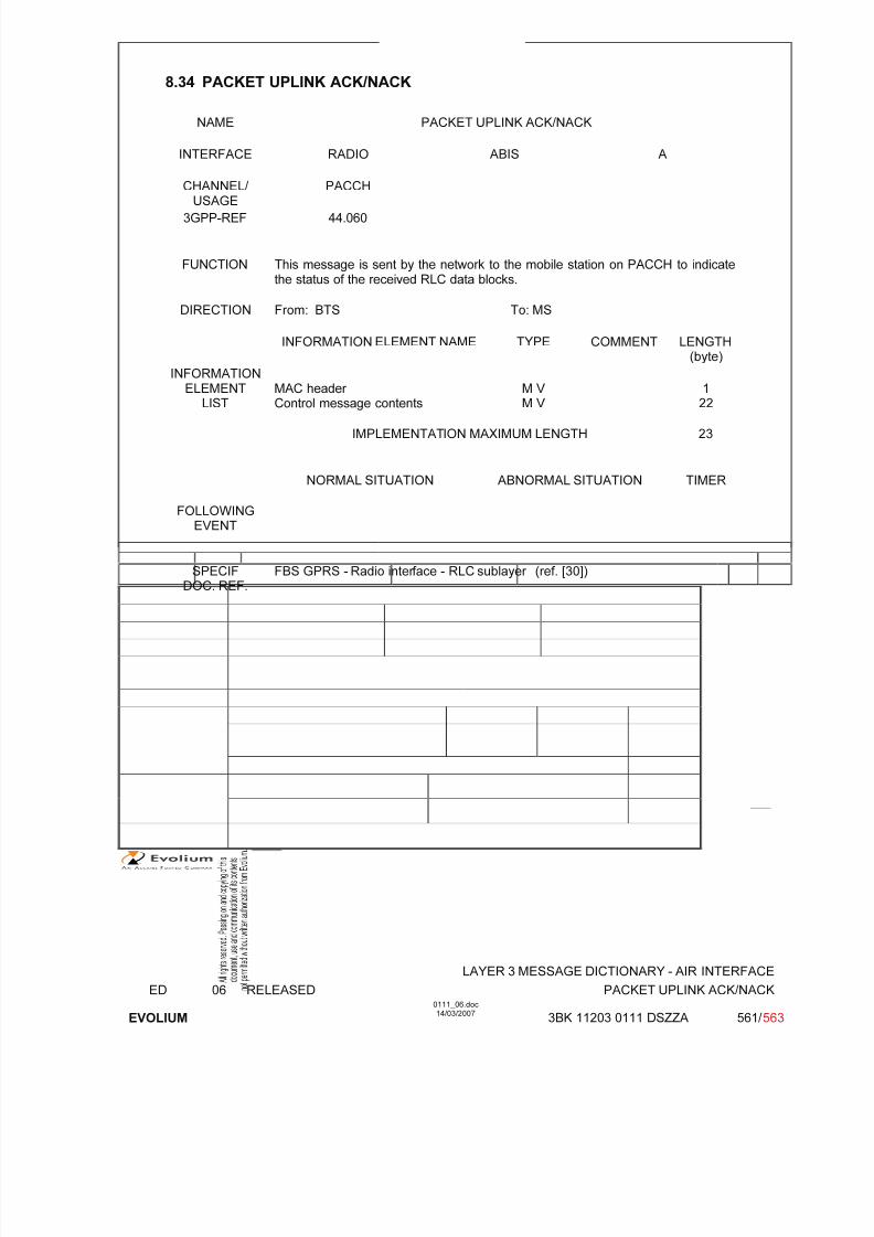
7/11/2019 1. Layer3 Air Interface Messages 0111_06
http://slidepdf.com/reader/full/1-layer3-air-interface-messages-011106 561/562
LAYER 3 MESSAGE DICTIONARY - AIR INTERFACE
ED 06 RELEASED PACKET UPLINK ACK/NACK
EVOLIUM
0111_06.doc14/03/2007
3BK 11203 0111 DSZZA 561/ 563
8.34 PACKET UPLINK ACK/NACK
NAME PACKET UPLINK ACK/NACK
INTERFACE RADIO ABIS A
CHANNEL/ USAGE PACCH
3GPP-REF 44.060
FUNCTION This message is sent by the network to the mobile station on PACCH to indicatethe status of the received RLC data blocks.
DIRECTION From: BTS To: MS
INFORMATION ELEMENT NAME TYPE COMMENT LENGTH(byte)
INFORMATIONELEMENT
LISTMAC header Control message contents
M V M V
122
IMPLEMENTATION MAXIMUM LENGTH 23
NORMAL SITUATION ABNORMAL SITUATION TIMER
FOLLOWINGEVENT
SPECIFDOC. REF.
FBS GPRS - Radio interface - RLC sublayer (ref. [30])

7/11/2019 1. Layer3 Air Interface Messages 0111_06
http://slidepdf.com/reader/full/1-layer3-air-interface-messages-011106 562/562
8.35 PACKET UPLINK ASSIGNMENT
NAME PACKET UPLINK ASSIGNMENT
INTERFACE RADIO ABIS A
CHANNEL/ USAGE PCCCH or PACCH
3GPP-REF 44.060
FUNCTION This message is sent by the network to the mobile station on PCCCH or PACCH