1. Introduction - Tokushima Ufemto.me.tokushima-u.ac.jp/introduction/thz/3-5/slide1.pdf ·...
30
Osaka University 1. Introduction
Transcript of 1. Introduction - Tokushima Ufemto.me.tokushima-u.ac.jp/introduction/thz/3-5/slide1.pdf ·...

Osaka University
1. Introduction

Osaka University
Background Frequency is a fundamental physical
quantity of electromagnetic wave
However, techniques of frequency measurement in THz region have been underdeveloped yet.
Advent of practical CW-THz sources (THz-QCL, UTC-PD,
RTD, etc)
Maintenance of THz frequency metrology is required for various
THz applications
Precise frequency measurement of CW-THz wave is required!

Osaka University
Conventional method (1) Frequency calibration based on water vapor absorption
ref) http://spec.jpl.nasa.gov/
Simple Pressure broadening of absorption line, discrete distribution

Osaka University
Conventional method (2) Electrical heterodyned method Optical interferometric method
cooling cooling
ΔL=(λ/2)*N
Difficult to cover all frequency region of THz wave (0.1~10THz) →Requirement of new method optimized for THz wave!

Osaka University
Optical comb and THz comb
Accurate, stable, broadband selectivity, high spectral purity, and absolute frequency calibration
Frequency ruler in THz region!
Photocarrier THz comb (PC-THz-comb)

Osaka University
Principle
(ML freq. = f)
(freq. = fx) Freq. domain
m: order of comb mode f: ML freq. fb: beat freq.
fb = fx −mfsign
measure

Osaka University
Determination of order of m
Shift of ML freq. by δf (f ® f+δf)
Change of beat freq. by δfb (fb ® fb+δfb)
m =δfbδf
fx = mf − fb (δfb/δf > 0)fx = mf + fb (δfb/δf < 0)

Osaka University
2. Ti:S-laser-based THz spectrum analyzer

Osaka University
Laser source for PC-THz comb

Osaka University
Stability of mode-locked frequency
Stability and accuracy of PC-THz comb is equal to those of Rb freq. standard

Osaka University
Experimental setup

Osaka University
Observation of beat signal (1) (90GHz freq. multiplier source)
f=81.6MHZ

Osaka University
Observation of beat signal (2)
fb signal
Signal-to-noise ratio Linewidth
>50dB
RBW=1Hz, sweep time=2.294s RBW=1kHz, sweep time=773ms
2.5mW@ test source
<0.6Hz@ test source
Detection limit = 25nW Linewidth < 1Hz
(90GHz freq. multiplier source)

Osaka University
Observation of beat signal (3)
RBW=100Hz, sweep time=165ms, full span=2kHz
Laser control : OFF Laser control : ON
(90GHz freq. multiplier source)

Osaka University
Observation of beat signal (4)
Freq. modulation of test source(100GHz±[email protected])
RBW=3kHz, sweep time=50ms,full span=300kHz
(freq. multiplier source wave)

Osaka University
Determination of absolute frequency ~Shift of ML frequency by 100Hz~
m =δfbδf
=454,027.976 − 333,027.731
81,823,857 − 81,823,757 =1210.00245
fx = mf + fb =1210 *81,823,757 + 454,027.976 = 99,007,119,997.976 Hz
Setting freq. of test source=99,007,200,000 Hz
error=2.004Hz

Osaka University
Frequency tuning of test source
Precision=2.8*10-11

Osaka University
3. Fiber-laser-based THz spectrum analyzer
~simple, compact, inexpensive, and robust system~

Osaka University
Er-doped fiber laser
PZT
Temp. control (Peltier)
ref) H. Inaba et al, Opt. Express 14, 5223 (2006)

Osaka University
Stabilization system of ML frequency

Osaka University
Photograph and cost of home-build fiber laser
COST
OSC ¥ 700,000
EDFA ¥ 650,000
Control electronics ¥ 400,000
45 cm
EDFA OSC

Osaka University
Autocorrelation signal and spectrum
Average power = 90mW@1550nm or 10mW@775nm Mode-locked frequency = 56MHz

Osaka University
Stability of ML frequency of fiber laser

Osaka University
Experimental setup
4mW

Osaka University
Observation of beat signal (1)
fb signal
Signal-to-noise ratio Linewidth
2.5mW@ test source
<0.6Hz@ test source
Detection limit = 2.5nW Linewidth < 1Hz
(80GHz active frequency multiplier)
60 dB

Osaka University
Comparison of fb beat signal Bowtie-type LTG-GaAs PCA

Osaka University
Frequency tuning of test source
Mean precision=2.2*10-11
(active frequency multiplier)

Osaka University
Experimental setup for UTC-PD

Osaka University
Real-time monitoring of beat signal 80GHz active freq. multiplier
(2.5 mW) 120GHz UTC-PD
(0.1 mW) Freq. span = 2 kHz Freq. span = 1.5 MHz
Sweep time=20 ms, RBW=10 kHz Sweep time=165 ms, RBW=100 Hz
Osaka University
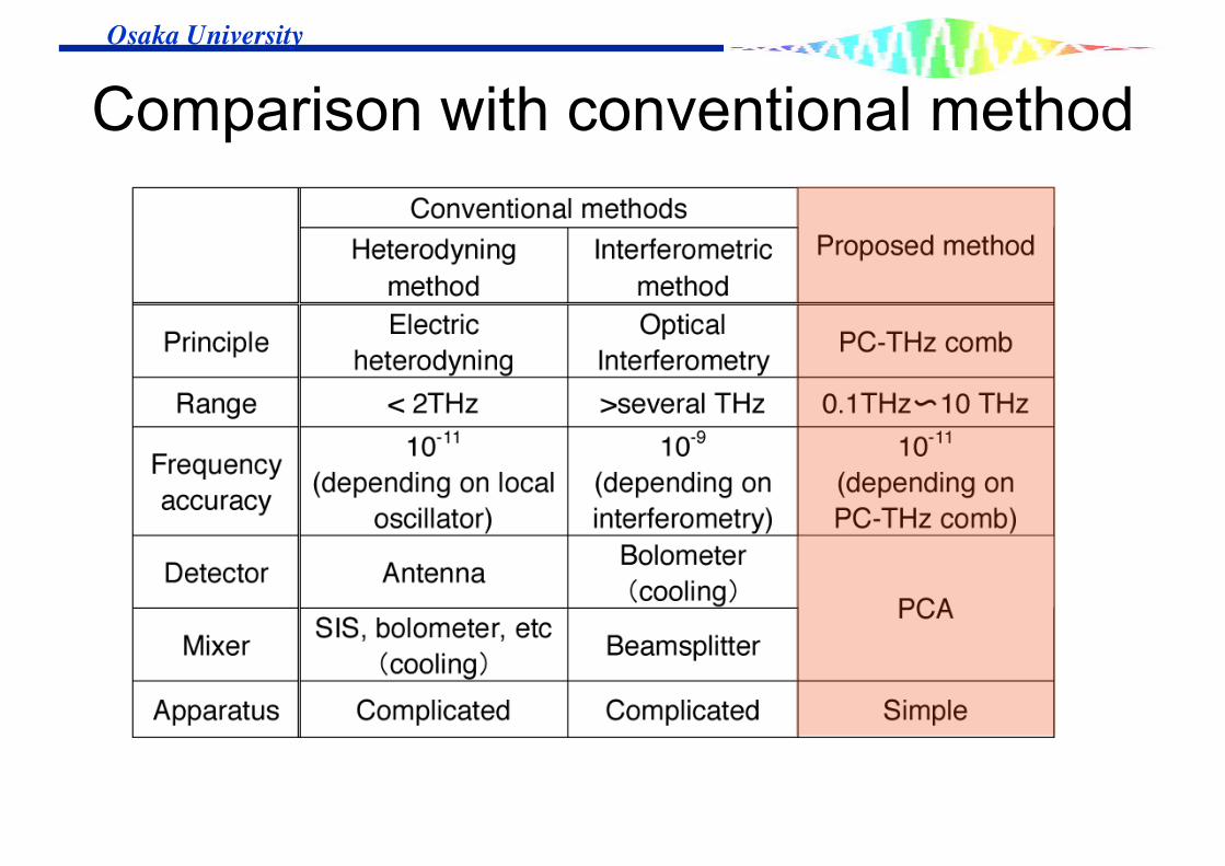
Comparison with conventional method