1 INTRODUCTION INSTALLATION INSTRUCTIONS 1 … OPERATED PHOTOELECTRIC DETECTOR AX-100TFR/AX-200 TFR...
12
-1- Warning Caution Warning Caution N219 1 2 3 4 5 6 INSTALLATION INSTRUCTIONS No.59-1552-1 090403 BATTERY OPERATED PHOTOELECTRIC DETECTOR AX-100TFR/AX-200 TFR BATTERY OPERATED PHOTOELECTRIC DETECTOR AX-100TFR/AX-200 TFR •AX-100TFR : Detection range: 30 m (100 ft.) •AX-200TFR : Detection range: 60 m (200 ft.) CONTENTS • Battery-operated detector Batteries are not included. Use four LSH20 (3.6 V, 13 Ah) batteries manufactured by SAFT. Battery life: AX-100TFR Approximately five years AX-200TFR Approximately three years (transmitter) Approximately five years (receiver) • Back box for wireless transmitters Back box can conceal two wireless transmitters and batteries. • N.C./N.O. selection switch Both N.C. and N.O. input wireless transmitters can be used. • Battery saving function for wireless transmitter Turning ON the battery saving timer switch reduces the battery consumption of the wireless transmitter. • Intermittent output function Turning ON the intermittent output function, alarm signals are sent periodically to avoid missed alarms while the beam is broken. • 4 channel beam frequency selector Crosstalk is eliminated with 4, channel selectable, beam frequencies. Used when stacking beams or for long range applications. • International protection IP55 • LED indicator for an easy alignment It flickers on/off to help with easy alignment located on the receiver. • D.Q. circuit (environmental disqualification) The environmental compensation circuit is designed to eliminate false alarms caused by snow, fog, heavy rain, ice and misalignment. • Tamper Form C output activates when either cover or back box or chassis is removed. • Beam interruption adjustment function This function allows you to select the suitable beam interruption time for any environment. FEATURES Failure to follow the instructions provided with this indication and improper handling may cause death or serious injury. Failure to follow the instructions provided with this indication and improper handling may cause injury and/or property damage. Do not use the product for purposes other than the detection of moving objects such as people and vehicles. Do not use the product to activate a shutter, etc., which may cause an accident. Do not touch the unit base or power terminals of the product with a wet hand (do not touch when the product is wet with rain, etc.). It may cause electric shock. Never attempt to disassemble or repair the product. It may cause fire or damage to the devices. Do not use batteries other than those specified. Specified batteries: Four LSH20 batteries manufactured by SAFT Do not use batteries that have different levels of power remaining (i.e., new and used batteries). Not observing the above may result in an explosion, leakage of electrolyte, emission of toxic gases or other outcomes that may be harmful to people and property. [Handling of Batteries] Fire, explosion and severe burn hazard. Do not recharge, short circuit, crush, disassemble, heat above 100°C (212°F), incinerate, or expose contents to water. Do not solder directly to the cell. Do not pour water over the product with a bucket, hose, etc. The water may enter, which may cause damage to the devices. Clean and check the product periodically for safe use. If any problem is found, do not attempt to use the product as it is and have the product repaired by a professional engineer or electrician. • Read this instruction manual carefully prior to installation. • After reading, store this manual carefully in an easily accessible place for reference. • This manual uses the following warning indications for correct use of the product, harm to you or other people and damage to your assets, which are described below. Be sure to understand the description before reading the rest of this manual. This symbol indicates prohibition. The specific prohibited action is provided in and/or around the figure. This symbol requires an action or gives an instruction. INTRODUCTION 1-1 BEFORE YOUR OPERATION 1 1-2 PRECAUTIONS 2 1-3 PARTS IDENTIFICATION 2 PREPARATIONS 2-1 ORDERING DETECTOR BATTERIES 2 2-2 CHECKING THE WIRELESS TRANSMITTER SIZE 2 INSTALLATION 3-1 WALL MOUNTING 3 3-2 POLE MOUNTING 4 3-3 MOUNTING IN THE BEAM TOWER 5 3-4 WIRING 7 SETTING 4-1 FUNCTION 8 4-2 4 CHANNEL BEAM FREQUENCY SELECTOR 8 4-3 OPTICAL ALIGNMENT 9 4-4 BEAM INTERRUPTION ADJUSTMENT 9 4-5 ADJUSTING OUTPUT 10 OPERATION CHECK 5-1 LED INDICATION 11 5-2 OPERATION CHECK 11 5-3 TROUBLE SHOOTING 11 SPECIFICATIONS 6-1 SPECIFICATIONS 12 6-2 DIMENSIONS & OPTION 12 INTRODUCTION 1 1-1 BEFORE YOUR OPERATION
Transcript of 1 INTRODUCTION INSTALLATION INSTRUCTIONS 1 … OPERATED PHOTOELECTRIC DETECTOR AX-100TFR/AX-200 TFR...

-1-
Warning
Caution
Warning
Caution
N219
1
2
3
4
5
6
INSTALLATION INSTRUCTIONSNo.59-1552-1 090403
BATTERY OPERATED PHOTOELECTRIC DETECTOR
AX-100TFR/AX-200 TFRBATTERY OPERATED PHOTOELECTRIC DETECTOR
AX-100TFR/AX-200 TFR•AX-100TFR : Detection range: 30 m (100 ft.)•AX-200TFR : Detection range: 60 m (200 ft.)
CONTENTS
• Battery-operated detectorBatteries are not included.Use four LSH20 (3.6 V, 13 Ah) batteries manufactured by SAFT. Battery life: AX-100TFR Approximately five years AX-200TFR Approximately three years (transmitter)
Approximately five years (receiver) • Back box for wireless transmitters
Back box can conceal two wireless transmitters and batteries.• N.C./N.O. selection switch
Both N.C. and N.O. input wireless transmitters can be used.• Battery saving function for wireless transmitter
Turning ON the battery saving timer switch reduces the battery consumption of the wireless transmitter.
• Intermittent output functionTurning ON the intermittent output function, alarm signals are sent periodically to avoid missed alarms while the beam is broken.
• 4 channel beam frequency selectorCrosstalk is eliminated with 4, channel selectable, beam frequencies. Used when stacking beams or for long range applications.
• International protectionIP55
• LED indicator for an easy alignmentIt flickers on/off to help with easy alignment located on the receiver.
• D.Q. circuit (environmental disqualification)The environmental compensation circuit is designed to eliminate false alarms caused by snow, fog, heavy rain, ice and misalignment.
• TamperForm C output activates when either cover or back box or chassis is removed.
• Beam interruption adjustment functionThis function allows you to select the suitable beam interruption time for any environment.
FEATURESFailure to follow the instructions provided with this indication and improper handling may cause death or serious injury.Failure to follow the instructions provided with this indication and improper handling may cause injury and/or property damage.
Do not use the product for purposes other than the detection of moving objects such as people and vehicles.Do not use the product to activate a shutter, etc., which may cause an accident.Do not touch the unit base or power terminals of the product with a wet hand (do not touch when the product is wet with rain, etc.). It may cause electric shock.Never attempt to disassemble or repair the product. It may cause fire or damage to the devices.Do not use batteries other than those specified.Specified batteries: Four LSH20 batteries manufactured by SAFTDo not use batteries that have different levels of power remaining (i.e., new and used batteries).Not observing the above may result in an explosion, leakage of electrolyte, emission of toxic gases or other outcomes that may be harmful to people and property.[Handling of Batteries]Fire, explosion and severe burn hazard. Do not recharge, short circuit, crush, disassemble, heat above 100°C (212°F), incinerate, or expose contents to water. Do not solder directly to the cell.
Do not pour water over the product with a bucket, hose, etc. The water may enter, which may cause damage to the devices.Clean and check the product periodically for safe use. If any problem is found, do not attempt to use the product as it is and have the product repaired by a professional engineer or electrician.
• Read this instruction manual carefully prior to installation.• After reading, store this manual carefully in an easily accessible place for reference.
• This manual uses the following warning indications for correct use of the product, harm to you or other people and damage to your assets, which are described below. Be sure to understand the description before reading the rest of this manual.
This symbol indicates prohibition. The specific prohibited action is provided in and/or around the figure.
This symbol requires an action or gives an instruction.
INTRODUCTION1-1 BEFORE YOUR OPERATION 11-2 PRECAUTIONS 21-3 PARTS IDENTIFICATION 2PREPARATIONS2-1 ORDERING DETECTOR BATTERIES 22-2 CHECKING THE WIRELESS TRANSMITTER SIZE 2INSTALLATION3-1 WALL MOUNTING 33-2 POLE MOUNTING 43-3 MOUNTING IN THE BEAM TOWER 53-4 WIRING 7SETTING4-1 FUNCTION 84-2 4 CHANNEL BEAM FREQUENCY SELECTOR 84-3 OPTICAL ALIGNMENT 94-4 BEAM INTERRUPTION ADJUSTMENT 94-5 ADJUSTING OUTPUT 10OPERATION CHECK5-1 LED INDICATION 115-2 OPERATION CHECK 115-3 TROUBLE SHOOTING 11SPECIFICATIONS6-1 SPECIFICATIONS 126-2 DIMENSIONS & OPTION 12
INTRODUCTION11-1 BEFORE YOUR OPERATION

-2-
1 m (3.3 ft.)
Receiver
Transmitter (different model)
Transmitter
21
2
1
3
AX-100TFR Detection range: 30 m (100 ft.)AX-200TFR Detection range: 60 m (200 ft.)
Installation Height0.7 m - 1 m(2.3 ft. - 3.3 ft.)
Install the unit on a stable surface.
Install the pole in a location where sufficient stability can be ensured.
Do not install the unit in a location where trees, leaves, or other objects that may swing in the wind may block the beam.
Do not install the receiver in a location where it is exposed to direct sunlight.
Observe the prescribed transmitter-receiver distance (range) and installation height.
The pole size should be 43 - 48 mm ( 1.69" - 1.89").
Do not allow the infrared beam from a different model to reach the receiver.
Install the unit more than 1 m (3.3 ft.) away from the wall or fence that are running parallel to the beam.
ChassisBack boxMain unitCover
Back box lock screwHarness retainer plateCover lock screw
Accessories>>
Removing the Back Box >>
Removing the Cover >>
Velcro tape: 2 setsU-brackets: 2Mounting plate
lock screws Pole mounting bracket set
Pole brackets: 6
M3×8 screws: 6M4×20 screws: 4M4×30 screws: 4
Loosen the back box lock screw.
Pull
Press
Loosen the cover lock screw.
Pull
Use two wireless transmitters for the each of receivers and transmitters. When wireless transmitters with two or more inputs are available, use one wireless transmitter for the each of transmitters and receivers.The following figure shows the dimensions of the wireless transmitter installation space in the back box. Note that transmitters with dimensions greater than those are not applicable.
Specified batteries: Four LSH20 batteries manufactured by SAFTFor information about batteries, visit the following website and contact your local SAFT sales representative.http://www.saftbatteries.com/Contacts/tabid/72/FP/9/FROM/PRODUIT/Default.aspx
• Be sure to monitor the alarm and low battery outputs.• To monitor the tamper output, include a wireless transmitter
supporting three or more inputs into the system.
Note>>
1-2 PRECAUTIONS
PREPARATIONS2
2-1 ORDERING DETECTOR BATTERIES
2-2 CHECKING THE WIRELESS TRANSMITTER SIZE
1-3 PARTS IDENTIFICATION42.5 (1.67)
42.5 (1.67)
26.5 (1.04)26.5
(1.04)
78 (3
.07)
78 (3
.07)
66 (2.60)
154
(6.0
6)
154
(6.0
6)
Unit: mm (inch)
The cross ( ) mark indicates prohibition.

-3-
1
2
3
Remove the chassis from the back box.
Fix the chassis to the wall.
Connect the cables from the back box to the wireless transmitters.
Wall mounting screws (M4×20, supplied)
Receiver-Wireless Transmitter Connection
Yellow/Yellow-white cable: For alarmGreen/Green-white cable: For low batteryBlack/Black-white cable: For tamper
Transmitter-Wireless Transmitter Connection
Green/Green-white cable: For low batteryBlack/Black-white cable: For tamper
Insert the specified batteries into the back box.
Fix the wireless transmitters in the back box.
Run the cables so that they are not pinched between the chassis and back box.
Install the back box onto the chassis.
Tighten the back box lock screw.
Warning• Do not use batteries other than those specified. Specified batteries: Four LSH20 batteries manufactured by SAFT• Do not mix batteries that have different levels of
power remaining (i.e., new and used batteries). Not observing the above may result in an explosion,
leakage of electrolyte, emission of toxic gases or other outcomes that may be harmful to people and property.
Caution• When N.O. wireless transmitters are used, see
“Using the N.O. type transmitter” in sec. “3-4” to change the wiring.
• Use the specified batteries for the wireless transmitters.
Cut the supplied Velcro tape to an appropriate length and apply.
4
5
6
7
Specified batteriesSAFT LSH203.6 V 13 Ah
INSTALLATION3
3-1 WALL MOUNTING
CautionAfter mounting the chassis, wiggle the tamper bushing with your thumb and forefinger to ensure the tamper works properly.
CautionRemove all batteries prior to replacing with new ones. If this is not followed, the low battery indicator LED will not reset and continue to flicker.

-4-
Tighten the back box lock screw.
1
2
3
4
5Remove the chassis from the back box.
Using a screwdriver or similar tool, break the knockout portion as shown.
Install three pole mounting brackets on the chassis.
Fix the chassis on the pole.
Take steps 3 through 6 refer to sec. “3-1” to install the wireless transmitters and batteries in the back box, and then install the back box on the chassis.
Knockout two locations pairing in a horizontal line.
Install the bracket in the knocked-out locations in step 2 .
Install the bracket in the knocked-out locations in step 2 .
Pole mounting bracket (supplied)
M3×8 screw (supplied)
U-bracket (supplied)
M4×30 screw (supplied)
Remove the chassis from the back box.
Using a screwdriver or similar tool, break the knockout portion as shown.
Install three pole mounting brackets on the chassis.
Choose a different pair of knockouts.
Pole mounting bracket (supplied)
M3×8 screw (supplied)
Pole mounting bracket (supplied)
M3×8 screw (supplied)
1
2
3
Detector 1 Detector 2
Detector 1 Detector 2
3-2 POLE MOUNTING-Single set
-Two detectors in opposing directions
After mounting the chassis, wiggle the tamper bushing with your thumb and forefinger to ensure the tamper works properly.
Caution
-5-
Caution
1
2
3
4
5
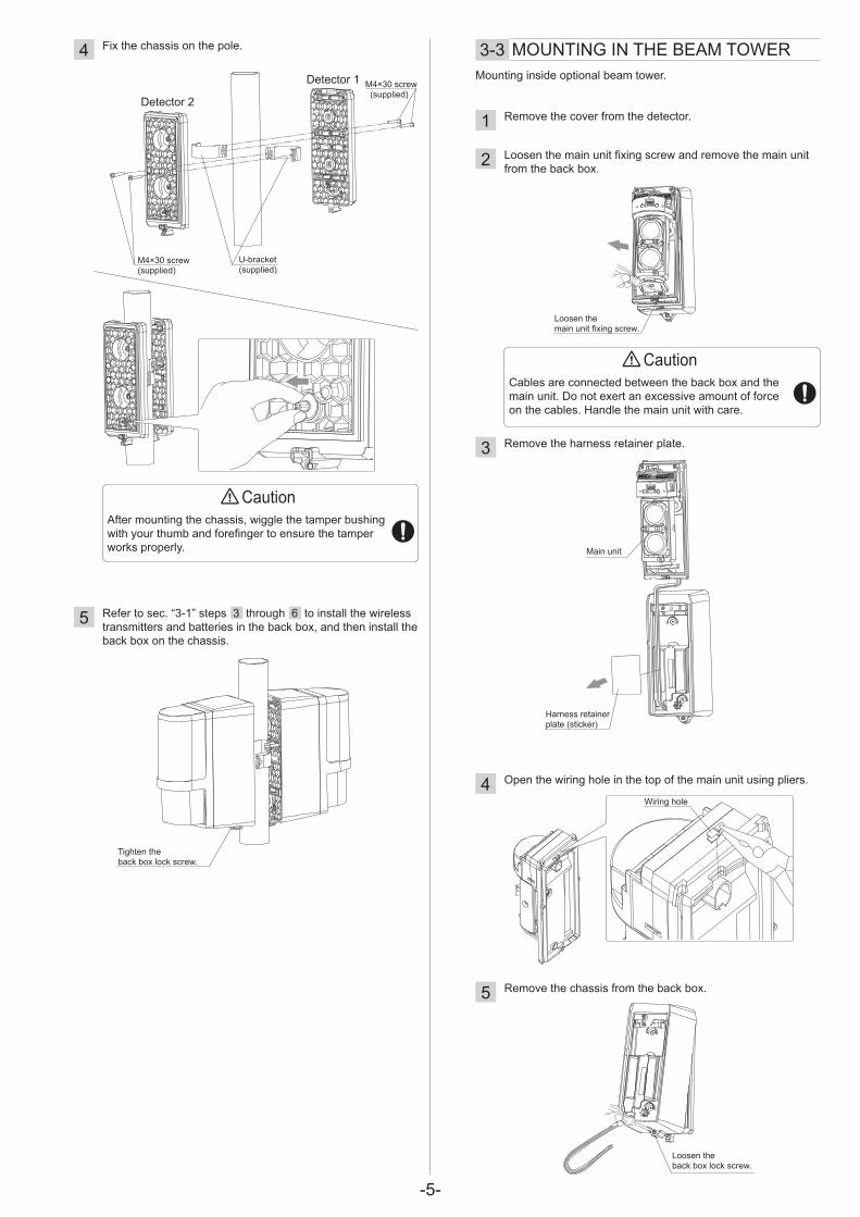
Remove the cover from the detector.
Loosen the main unit fixing screw and remove the main unit from the back box.
Remove the harness retainer plate.
Open the wiring hole in the top of the main unit using pliers.
Remove the chassis from the back box.
Loosen the back box lock screw.
Wiring hole
Loosen the main unit fixing screw.
Main unit
Harness retainer plate (sticker)
Cables are connected between the back box and the main unit. Do not exert an excessive amount of force on the cables. Handle the main unit with care.
3-3 MOUNTING IN THE BEAM TOWER
Tighten the back box lock screw.
Fix the chassis on the pole.
Refer to sec. “3-1” steps 3 through 6 to install the wireless transmitters and batteries in the back box, and then install the back box on the chassis.
U-bracket (supplied)
M4×30 screw (supplied)
M4×30 screw (supplied)
4
5
Detector 1
Detector 2
CautionAfter mounting the chassis, wiggle the tamper bushing with your thumb and forefinger to ensure the tamper works properly.
Mounting inside optional beam tower.

-6-
Caution
Tamper bushing(option: MP-4)
After completing the settings and operation check, insert the tamper bushing into each transmitter/receiver.8
• The switch selection is not recognized with the tamper bushing inserted.
Remove the tamper bushing before selecting a function using the switch.
• After completing the settings, be sure to insert the tamper bushing to check that all LEDs are OFF.
Without the tamper busing, the LEDs are kept ON, which consumes more battery power.
• Monitor Jack Output become disable when tamper bushing inserted.
• When inserting the tamper bushing, the beam alignment test point will be disabled. Please complete the alignment procedure before inserting tamper bushing.
Insert a flat-blade screwdriver, and twist it lightly to remove the tamper bushing.
How to remove the tamper bushing >>
Tighten the screws.
Fix the chassis and main unit mounting bracket (optional) in the tower.
Refer to sec. “3-1” steps 3 through 6 to install the wireless transmitters and batteries in the back box, and then install the back box on the chassis.Install the main unit on the main unit mounting bracket.
Main unit mounting bracket (option: MP-4)
6
7
CautionAfter mounting the chassis, wiggle the tamper bushing with your thumb and forefinger to ensure the tamper works properly.
250
mm
(9.8
inch
) or l
ess

-7-
+ – NC COM NO
+ – NC COM NO
+ – NC COM NO + – NC COM NO
+ – NC COM NO + – NC COM NO
NC COM NO+ –SP SP
NC/NO
+ – NC COM NO NC COM NONC/NO NC/NO+ – NC COM NO NC COM NONC/NO NC/NO
+ –SP SP
NC/NO + –SP SP
NC/NO
+ –SP SP
NC/NO NC COM NO
POWER ALARM DQ LB TAMPER POWER ALARM DQ LB TAMPER
POWER
SP SP
LB POWER
SP SP
LB
TAMPERPOWER
SP SP
LB TAMPERPOWER
SP SP
LB
Gre
en
Gre
en-w
hite
Black
Black-white
Bla
ck-w
hite
When N.O. wireless transmitters are used, change the wiring and switch settings from initial setting.
This product is provided with wiring based on the assumption that N.C. wireless transmitters are used.Connect the cables from the back box (Yellow/Yellow-white, Green/Green-white, and Black/Black-white) to the respective terminals on the wireless transmitters.
Receivers
Back box
Back box
TransmitterAX-100/200TFR
TransmitterAX-100/200TFR (BE)
Alarmoutput
Low batteryoutput
TamperoutputPOWER TAMPER
Receivers
Back box
Back box
Wireless transmitter
Red
Red
-whi
te
Gre
en
Gre
en-w
hite
Black
Bla
ck-w
hite
Bla
ck-w
hite
Black
Alarmoutput
Low batteryoutput
Tamperoutput
POWER TAMPER
Wireless transmitter
Red
Red
-whi
te
Yellow
Yellow-whiteYellow
Yellow-white
Gre
en
Gre
en-w
hite
Bla
ck-w
hite
Black
Black
Low batteryoutput
TamperoutputPOWER TAMPER
Wireless transmitter
Red
Red
-whi
te
Gre
en
Gre
en-w
hite
Bla
ck-w
hiteBlack
Black
Low batteryoutput
TamperoutputPOWER TAMPER
TransmitterAX-100/200TFR
Back box Wireless transmitter
Red
Red
-whi
te
Gre
en
Gre
en-w
hite
Bla
ck-w
hite
Blac
k-wh
ite
Black
Black
Exchange the connections.
Cut the wires and connect to two terminals.
Turn ON switch No. 5.
Turn ON switch No. 3.
Exchange the connections.
Cut the wires and connect to two terminals.
Turn ON switch No. 3.
Exchange the connections.Cut the wires and connect to two terminals.
Back box
Low batteryoutput
TamperoutputPOWER TAMPER
Wireless transmitter
Red
Red
-whi
te
Gre
en
Gre
en-w
hite
Bla
ck-w
hite
Black
Black
TransmitterAX-100/200TFR (BE)
Back box
Low batteryoutput
TamperoutputPOWER TAMPER
Wireless transmitter
Red
Red
-whi
te Black
• To monitor the tamper output, include a wireless transmitter supporting three or more inputs into the system.
• When you want to use the D.Q. output, share the terminal with the alarm, low battery, or tamper output. For information about wiring, see the wiring diagram in “Setting the D.Q. output” in “4-5”.
NOTE>>
3-4 WIRING-Using the N.C. type transmitter -Using the N.O. type transmitter
-8-
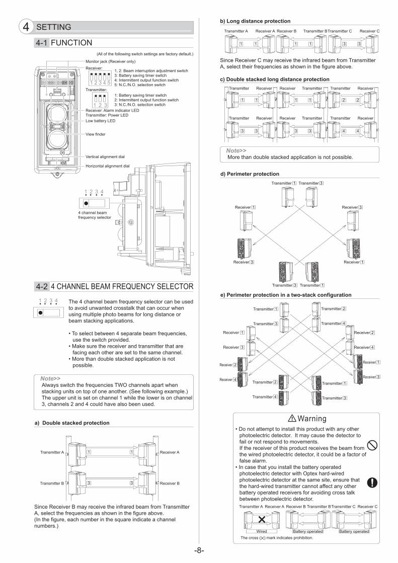
1, 2: Beam interruption adjustment switch3: Battery saving timer switch4: Intermittent output function switch5: N.C./N.O. selection switch
1: Battery saving timer switch2: Intermittent output function switch3: N.C./N.O. selection switch
Monitor jack (Receiver only)
Receiver: Alarm indicator LEDTransmitter: Power LEDLow battery LED
Vertical alignment dial
Horizontal alignment dial
View finder
4 channel beam frequency selector
Receiver:
Transmitter:
4-2 4 CHANNEL BEAM FREQUENCY SELECTOR
Warning
The 4 channel beam frequency selector can be used to avoid unwanted crosstalk that can occur when using multiple photo beams for long distance or beam stacking applications.
• To select between 4 separate beam frequencies, use the switch provided.
• Make sure the receiver and transmitter that are facing each other are set to the same channel.
• More than double stacked application is not possible.
a) Double stacked protection
Since Receiver B may receive the infrared beam from Transmitter A, select the frequencies as shown in the figure above.(In the figure, each number in the square indicate a channel numbers.)
b) Long distance protection
Since Receiver C may receive the infrared beam from Transmitter A, select their frequencies as shown in the figure above.
c) Double stacked long distance protection
d) Perimeter protection
e) Perimeter protection in a two-stack configuration
Transmitter A Receiver A
Transmitter B Receiver B
Transmitter A Receiver A
1 1
1 1
3 3
Transmitter Receiver
Transmitter Receiver
1 1
Transmitter
Receiver
1
Transmitter 1Transmitter 3
Transmitter 3
1
Receiver 1 Receiver 3
Receiver 3
Transmitter
Receiver
1
Transmitter 1Transmitter 2
Transmitter 2
1
Receiver 1 Receiver 2
Receiver 2
Transmitter
Receiver
3
Transmitter 3Transmitter 4
Transmitter 4
3
Receiver 3 Receiver 4
Receiver 4
3 3
Receiver Transmitter
Receiver Transmitter
1 1
3 3
Transmitter Receiver
Transmitter Receiver
2 2
4 4
Receiver B Transmitter B
1 1
Transmitter C Receiver C
3 3
Transmitter A Receiver A
Wired Battery operated Battery operated
Receiver B Transmitter BTransmitter C Receiver C
SETTING44-1 FUNCTION
More than double stacked application is not possible.Note>>
Always switch the frequencies TWO channels apart when stacking units on top of one another. (See following example.) The upper unit is set on channel 1 while the lower is on channel 3, channels 2 and 4 could have also been used.
Note>>
• Do not attempt to install this product with any other photoelectric detector. It may cause the detector to fail or not respond to movements. If the receiver of this product receives the beam from the wired photoelectric detector, it could be a factor of false alarm.
• In case that you install the battery operated photoelectric detector with Optex hard-wired photoelectric detector at the same site, ensure that the hard-wired transmitter cannot affect any other battery operated receivers for avoiding cross talk between photoelectric detector.
(All of the following switch settings are factory default.)
The cross ( ) mark indicates prohibition.
-9-
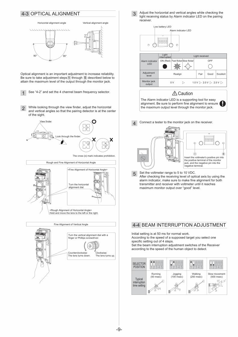
5°5°
90° 90°
Horizontal alignment angle Vertical alignment angle
Caution1
2
3
4
5
See “4-2” and set the 4 channel beam frequency selector.
While looking through the view finder, adjust the horizontal and vertical angles so that the pairing detector is at the center of the sight.
Adjust the horizontal and vertical angles while checking the light receiving status by Alarm indicator LED on the pairing receiver.
Connect a tester to the monitor jack on the receiver.
Set the voltmeter range to 5 to 10 VDC.After checking the receiving level of optical axis by using the alarm indicator, make sure to make fine alignment for both transmitter and receiver with voltmeter until it reaches maximum monitor output over “good” level.
Optical alignment is an important adjustment to increase reliability. Be sure to take adjustment steps 1 through 5 described below to attain the maximum level of the output through the monitor jack.
<Rough Alignment of Horizontal Angle>Hold and move the lens to the left or the right.
Turn the horizontal alignment dial.
Insert the voltmeter's positive pin into the positive terminal of the monitor jack, and the negative pin into the negative terminal.
Initial setting is at 50 ms for normal work.According to the speed of a supposed target you select one specific setting out of 4 steps.Set the beam interruption adjustment switches of the Receiver according to the speed of the human object to detect.
(50 msec) (100 msec) (250 msec) (500 msec)Typical
interruption time setting
SELECTORPOSITION
Low battery LED
Alarm indicator LED
Light interrupted Light received
Adjustment level
Monitor jack output
Realign Fair Good Excellent
0 V 1.0 V 2.0 V 2.5 V
Alarm indicator LED
ON (Red) Fast flicker Slow flicker OFF
<Fine Alignment of Horizontal Angle>
Fine Alignment of Vertical Angle
Rough and Fine Alignment of Horizontal Angle
Running Jogging Walking Slow movement
The Alarm indicator LED is a supporting tool for easy alignment. Be sure to perform fine alignment to ensure the maximum output level through the monitor jack.
Turn the vertical alignment dial with a finger or Phillips screwdriver.
Clockwise: The lens turns up.
Counterclockwise: The lens turns down.
View finder
Look through the finder.
4-3 OPTICAL ALIGNMENT
4-4 BEAM INTERRUPTION ADJUSTMENT
The cross ( ) mark indicates prohibition.

-10-
ON
OFF
ON
OFF
Caution
Caution
+ – NC COM NO
POWER TAMPER
+ – NC COM NOAlarmoutput
Low batteryoutput
TamperoutputPOWER TAMPER
+ – NC COM NO NC COM NONC/NO NC/NO
POWER ALARM DQ LB TAMPER
+ – NC COM NO NC COM NONC/NO NC/NO
POWER ALARM DQ LB TAMPER
This circuit sets N.O. for a low battery output, whereas N.C. for an alarm. Be sure to use N.O. ready wireless transmitter for this configuration.Turn “OFF” both battery saving timer and intermittent output function switches when applying this wiring example.
When wireless configuration is being used, which is unable to determine whether the alarm output continues, setting the intermittent output function to the “ON” position, turns on the intermittent alarm output.This configures the wireless transmitter to send alarms at a specific time intervals.
Intermittent Output Times• Alarm output: 1 output/1 minute• D.Q. output: 1 output/1 minute• Low battery output: 1 output/5 minutes
Alarm output activation are limited by a timer 2 minutes.Even if there are continuous alarm events, the alarm output operates only once in the timer period.
• Alarm output: 1 output/2 minute• D.Q. output: 1 output/2 minute• Low battery output: 1 output/15 minutes
D.Q. will send a trouble signal when the beam strength is below acceptable levels, for more than 20 seconds, due to rain, snow, or heavy fog.
20 sec.2 sec.
ONOFF
Reception level
Adverse weather level
Alarm output level
D.Q. output
Receiver
Back box Wireless transmitter
Red
Red
-whi
te
Gre
en
Gre
en-w
hite
Black
Yello
w-w
hite
Exchange the connections.
Add a short-circuit wireAWG 22 to 26Length of about 80 mm (3 inches)
Add a short-circuit wireAWG 22 to 26Length of about 80 mm (3 inches)
Receiver
Back box Wireless transmitter
Red
Red
-whi
te
Gre
en
Gre
en-w
hite
Black Turn OFF switch No. 3 & 4. Turn ON switch No. 5.
Yellow-white
Receiver Transmitter
Receiver Transmitter
Yellow
Black
Bla
ck-w
hite
Alarmoutput
Low batteryoutput
Tamperoutput
Yellow
Black
Bla
ck-w
hite
4-5 ADJUSTING OUTPUT
-Setting the intermittent output function
-Setting the D.Q. output (environmental disqualification)
-Setting the battery saving timer
Operating Time Chart
Wiring example when Using N.C. Transmittersa) Sharing the D.Q. output with the alarm output
Wiring example when Using N.C. Transmittersb) Canceling the alarm output in adverse weather conditions
Remove all batteries prior to replacing with new ones. If this is not followed, the low battery indicator LED will not reset and continue to flicker.

-11-
CautionFor battery power savings, perform the operation check before checking the following items.(1) When installing on a wall or pole, make sure the
cover is properly attached to main unit.(2) When installing in a beam tower, make sure the
tamper bushing is properly attached to main unit. (See page 6 “Caution”.)
1
2
3
4
See “Setting the battery saving timer” in “4-5” to turn OFF the battery saving mode.
Make sure that the alarm indicator is off.If it is illuminated even when the beams are not blocked, make optical alignment again.
Check that the low battery indicators on both transmitter and receiver are OFF.If the LED is flickering, the battery power is low.Replace with the new batteries.
Conduct a walk test to check that the alarm indicator LED on the receiver turns ON as the walker interrupts the beams.
12
3
After installation is complete, be sure to check the operation.
Be sure to conduct a walk test at the following three points:
A. In front of the transmitterB. In front of the receiverC. At the mid point between the transmitter and receiver
The detector is installed properly when the alarm indicator LED turns ON in the tests at all the three points.
Alarm indicator LED
Receiver
Low battery LED
Alarm indicator LED Power LED
Receiver Transmitter
Low battery LED Low battery LED
A
B
CTransmitter
Receiver
DETECTOR STATUS
Power ONDetection
(beam interruption)Low battery power
LED Indications
The power LED turns ON.
The alarm LED turns ON.
The low battery LED flickers.
OPERATION CHECK5
5-1 LED INDICATION
5-2 OPERATION CHECK
5-3 TROUBLE SHOOTINGIf the alarm indicator LED is OFF or flickering even though the beam is being interrupted, do the following:
Align the optical axis again.
In a multi-detector configuration, the receiver may be receiving the infrared beam from an unrelated transmitter. See sec. “4-2” and check the 4 channel beam frequency selector setting.
The beam from the transmitter may reach the receiver by reflecting off the floor or wall of a building. Good reflectors of visible light are also good reflectors of infrared beams. Remove the reflective objects around the detector or install the detector in a different place and then align the optical axis again.

-12-
OPTEX INCORPORATED (USA)TEL: +1-909-993-5770Tech: (800)966-7839 URL: http://www.optexamerica.com
OPTEX KOREA CO., LTD. (KOREA)TEL: +82-2-719-5971URL: http://www.optexkorea.com
OPTEX SECURITY Sp.z o.o. (POLAND)TEL: +48-22-598-06-55URL: http://www.optex.com.pl
OPTEX (DONGGUAN) CO., LTD.SHENZHEN OFFICE (CHINA)TEL: +86-755-33302950URL: http://www.optexchina.com
OPTEX CO., LTD. (JAPAN)(ISO 9001 Certified) (ISO 14001 Certified)5-8-12 Ogoto OtsuShiga 520-0101JAPANTEL: +81-77-579-8670FAX: +81-77-579-8190URL: http://www.optex.co.jp/e/
OPTEX (EUROPE) LTD. (UK)TEL: +44-1628-631000URL: http://www.optexeurope.com
OPTEX SECURITY SAS (FRANCE)TEL: +33-437-55-50-50URL: http://www.optex-security.com
Main unit mounting bracket
Tamper Bushing
Without the tamper busing, the LEDs are kept ON, which consumes more battery power.
NOTE
MP-4: Main unit mounting bracket set (for tower mounting)
These units are designed to detect an intruder and activatean alarm control panel. Being only a part of a completesystem, we cannot accept responsibility for any damagesor other consequences resulting from an intrusion.These products conform to the EMC Directive 2004/108/EC.
Specifications and design are subject to change without prior notice.* The value is based on the condition that it is used within the ambient temperature range of 20 to 25°C.** The transmitter is also equipped with AX100/200 TFR (BE).
SPECIFICATIONS6
Model
Range
Maximum arrival distance
Detection method
Beam frequency selection
Interruption period
Power Source
Current draw
* Battery life
Output
Indicator
Alarm output
Alarm period
D.Q. output
Low battery output
** Tamper output for Front cover
Tamper output for Back box
Alarm Indicator(Receiver) Power(Transmitter)Low battery
Operating temperature
Operating ambient humidity
Alignment angle
Mounting
Weight
International protection
AX-100TFR AX-200TFR
30 m (100 ft.) 60 m (200 ft.)
265 m (870 ft.) 530 m (1740 ft.)
Infrared beam interruption detection
4 channelVariable between 50, 100, 250, 500 msec
(4 steps) 3.6 V 13.0 Ah: LSH20 lithium batteries manufactured by SAFT (not installed)
Transmitter: 2 units Receiver: 2 units620 µA
T: 300 µA + R: 320 µA(at 25°C, 3.6 VDC)
5 years
810 µAT: 490 µA + R: 320 µA
(at 25°C, 3.6 VDC)3 years
5 years
Form C-Solid State Switch: 3.6 VDC, 0.01 A
2 sec (±1) nominal
Form A/B-Solid State Switch: 3.6 VDC, 0.01 A Form A/B-Solid State Switch: 3.6 VDC, 0.01 A
(Transmitter & Receiver)Form C: 3.6 VDC, 0.01 A
activates when cover removed. (Receiver only)Form C: 3.6 VDC, 0.01 A
activates when either back box or chassis is removed from the installment.
(1) Light on - IR Beam not received.(2) Flickering Light - IR Beams not received
sufficiently.(3) Light off - IR Beams received.
Power ON: ON, Power OFF: OFF
Voltage Reduction: flicker
-20°C – +60°C (-4°F – +140°F)
95% (Max.)
±90° Horizontal, ±5° Vertical
Indoor/Outdoor, Wall/Pole/Tower mounting(Optional main unit mounting brackets are
required, when the units mount in the tower.)
1600 g (56.5 oz.) (Total weight of transmitter + receiver,
excluding accessories)
IP55
88.1 (3.47)
217
(8.5
)
162.5 (6.4)
83.5
(3.2
8)
Unit: mm (inch)
6-1 SPECIFICATIONS
6-2 DIMENSIONS & OPTION-Dimensions
-Option
Transmitter
Receiver
83.
5 (3
.28)
Unit: mm (inch)