
1. Introduction - facta universitatis
32
Transcript of 1. Introduction - facta universitatis
FACTA UNIVERSITATIS (NI�S)
Series: Electronics and Energetics vol. 12, No.2 (1999), 1-32
UDC 621.395
GSM DATA RECEIVERS: AN OVERVIEW
This paper is dedicated to Professor Ilija Stojanovi�c on the occasion of the
50th anniversary of his scienti�c work as Professor of Telecommunications
at the University of Belgrade. His work has resulted in highly signi�cant con-
tributions to the design and development of wireline and wireless communica-
tion systems, education of numerous students in �eld of telecommunications
and important activities at the international level within the International
Telecommunicatios Union (ITU)
Bj�rn A. Bjerke, Zoran Zvonar
and John G. Proakis
Abstract. This paper presents an overview of data receivers for the GSM
system. First, the various phases of receiver evolution are identi�ed. Next, the
modulation format, the propagation channels and the system characteristics
that have direct impact on the receiver design are outlined. Important design
considerations and possible tradeo�s are identi�ed, followed by a discussion
of equalization techniques and a comparison of their performance. Implemen-
tation issues are also covered, in particular the tradeo� between exibility
and power consumption. We conclude by addressing recent advanced data
receiver developments such as EDGE, blind equalization, multiuser (joint)
detection and adaptive antenna arrays.
1. Introduction
The Global System for Mobile Communications (GSM) is currently the
most successful of digital cellular standards. It encompasses both cellular
(GSM-900) and PCS (DCS-1800, PCS-1900) systems, and has been adopted
by a large number of wireless operators around the world. The GSM system
Manuscript received June 24, 1999.
B. Bjerke and J. Proakis are with Department of Electrical and Computer Engi-
neering, Northeastern University, 360 Huntington Ave., Boston, MA 02115, USA, e-mail:
[email protected]. Z. Zvonar is with Analog Devices, Inc., Comunications Division, 804
Woburn St., Wilmington, MA 01887, USA, e-mail: [email protected] .
1
2 Facta Universitatis ser.: Elect. and Energ. vol. 12, No.2 (1999)
facilitates transmission of digitized speech and data, using a time division
multiple access (TDMA) scheme. General system overviews can be found in
[1] and [2].
While most parts of the system are covered in detail by the standard,
one of the critical parts, namely the data receiver, is speci�ed in terms of
performance only, thus leaving room for manufacturers and operators to
implement individual solutions. The data receiver largely determines the
performance of the GSM terminal and plays a major role in the type approval
procedure. It has critical impact on many features of the overall system, such
as coverage, voice quality and power consumption. The development of GSM
data receivers is a constantly evolving process, motivating the investigation
of performance and complexity of various receiver structures. In fact, the
data receiver is emerging as one of the major di�erentiators among di�erent
GSM terminal designs.
The GSM system su�ers from intersymbol interference (ISI) introduced
by both the partial response modulation employed and time-varying multi-
path propagation in the radio channel. As the symbol rate is high (270.8
kbits=s), the delay spread may extend over several symbol periods. Hence,
some form of channel equalization is needed. The equalizer is the critical el-
ement of the GSM data receiver, although other elements, performing tasks
such as frequency and symbol synchronization, bad frame indication, etc.,
are integral parts of the overall receiver solution as well.
Three phases can be identi�ed in the history of GSM data receiver
development. The �rst phase, spanning the late 1980s and early 1990s, covers
the development of the standard and early stages of deployment. The focus
in this period was on data receiver performance, with emphasis on speci�c
functions that could lead to improved performance and eventually lower
complexity. Given the dispersive nature of the propagation channel, the
optimal performance is obtained by using the maximum likelihood sequence
estimator (MLSE) [3], which has been adopted as the de facto standard
for GSM data receivers. However, its computational complexity is high
and increases exponentially with the length of the ISI. It was therefore of
interest to investigate receiver structures of lower complexity. Since then,
various other solutions have been proposed at the algorithmic level, including
suboptimal approaches such as reduced-state sequence estimation, decision
feedback equalization (DFE) and linear equalization.
The second development phase is associated with the massive deploy-
ment of GSM networks worldwide in the mid-1990s. In this phase, the major
performance aspects were well understood and algorithmic approaches had
B. Bjerke et al: GSM Data Receivers: An Overview 3
entered a mature stage. The focus in the second phase was on cost-e�ective
solutions, providing e�cient tradeo�s between performance and complexity.
The emphasis was shifted towards the architectural level, the goal being to
obtain an e�cient partitioning of the data receiver functions between hard-
ware and software.
The proliferation of integrated solutions with large computational ca-
pability on one side, and new system requirements resulting from micro
cells, co-existence of di�erent networks, etc., on the other side, marked the
transition into the third (current) phase. Operation in dense multipath
environments, performance limitations arising from co-channel interference
rather than noise, smaller cell sizes and new services such as packet data,
have spawned a new set of problems to be dealt with. Various advanced
techniques, ranging from multiuser (joint) detection via blind equalization
to adaptive antenna arrays, are currently being considered within the GSM
framework as responses to the new challenges
The paper is organized as follows. In Section 2, we give some back-
ground on GSM system parameters and present an overview of the modu-
lation method employed. In Section 3, we summarize the characteristics of
the GSM channel propagation models which are used to evaluate receiver
performance, and emphasize their impact on the design of receivers. Section
4 discusses the algorithmic aspects of the data receiver. Various channel
equalization techniques are considered, and a summary of their performance
is provided. In Section 5, the impact of the data receiver on the GSM ter-
minal architecture is considered, as well as algorithmic modi�cations due
to hardware constraints. Enhanced GSM receiver structures, utilizing more
advanced techniques such as blind equalization, space-time processing and
interference suppression, are discussed in Section 6. Concluding remarks are
given in Section 7.
2. GSM System Parameters and
GMSK Modulation
The GSM system uses 124 radio channels, each of which provides eight
user channels through the use of TDMA frames with eight time slots. Each
time slot provides room for a burst which contains data as well as a training
sequence which is used to estimate the channel impulse response. The burst
is phase modulated onto a 900MHz carrier using binary Gaussian minimum
shift keying (GMSK) with normalized bandwidth BT = 0:3, where B is the
bandwidth and T is the symbol duration.
On the basic GSM tra�c channel, so-called Normal Bursts of 148 error

4 Facta Universitatis ser.: Elect. and Energ. vol. 12, No.2 (1999)
protected and interleaved bits are transmitted in each time slot. A training
sequence of 26 bits is embedded at the middle of each burst, surrounded by
two data sequences of 58 bits each, as shown in Fig.1. The three tail bits at
each end of the burst are also known to the receiver, a fact which may be
exploited by the receiver.
0 1 2 3 4 5 6 7
TAIL DATA TRAINING DATA TAILTime slot
(3) (26) (3) (8.25)
Guard interval
148 bits burst
156.25 bits time slot
(58) (58)
TDMA frame
Fig. 1. The GSM Normal Burst structure
GMSK is a continuous phase modulation (CPM) technique which is
characterized by constant envelope and narrow bandwidth. Controlled ISI
is deliberately introduced to improve spectral e�ciency. The information is
carried by the phase of the transmitted signal and the total phase signal is
a linear function of the information sequence. Focusing on the nth symbol
interval, the complex baseband GMSK signal may be expressed by
s(t) = ej�(t) = ej[�
2
Pn�L
i=�1�i+�
Pn
i=n�L+1�iq(t�iT )]; (1)
where the �rst term of the phase represents the cumulative phase up to
symbol (n � L) and the second term represents the contribution from on-
going phase transitions due to the L previous symbols. f�ng represents theinformation sequence and q(t) is a phase response function de�ned by
q(t) =
Z t
�1
g(�)d�; (2)
where g(t) is a Gaussian-shaped frequency pulse, given by
g(t) =1
2T
�Q
�2�B(t� T=2)
pln 2
��Q
�2�B(t+ T=2)
pln 2
��: (3)
B. Bjerke et al: GSM Data Receivers: An Overview 5
Q(�) denotes the standard error function.
It has been shown that binary continuous phase modulations, which
are nonlinear by nature, can in general be constructed by linear superpo-
sition of a �nite number of amplitude modulated pulses, provided that the
frequency pulse g(t) is of �nite duration LT [5]. Approximations of phase
modulated signals may be generated using only a single optimized ampli-
tude modulated pulse. Thus, binary CPM schemes may be approximated
by linear modulations, which may help simplify the receiver structure as well
as signal generation at the transmitter [6]. In particular, such linear repre-
sentations allow standard equalization techniques to be used. The complete
and exact baseband description of a binary CPM signal is given by
s(t) = ej�(t) =
1Xn=�1
2L�1�1Xk=0
ej�
2Ak;nCk(t� nT ): (4)
We observe that the phase modulation now is expressed as a sum of 2L�1
distinct real-valued pulses Ck(t), each weighted by a complex coe�cient
JAk;n , where J = ej�=2 and Ak;n is given by
Ak;n =
nXi=�1
�i �L�1Xi=1
�n�1ak;i: (5)
ak;i is associated with the binary-valued index k, given by
k =
L�1Xi=1
2i�1ak;i; ak;i 2 f0; 1g; k = 0; : : : ; 2L�1 � 1: (6)
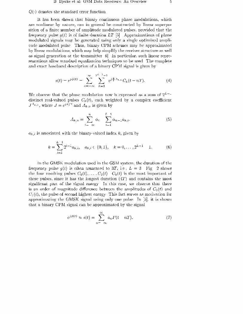
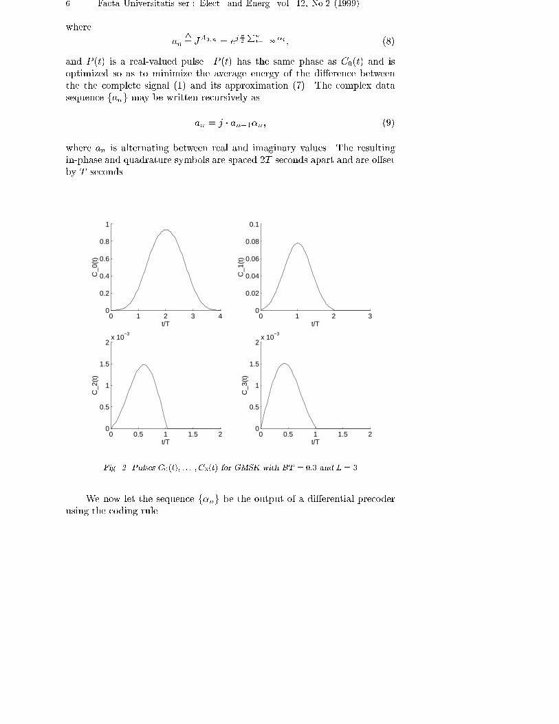
In the GMSK modulation used in the GSM system, the duration of the
frequency pulse g(t) is often truncated to 3T , i.e., L = 3. Fig. 2 shows
the four resulting pulses C0(t); : : : ; C3(t). C0(t) is the most important of
these pulses, since it has the longest duration (4T ) and contains the most
signi�cant part of the signal energy. In this case, we observe that there
is an order of magnitude di�erence between the amplitudes of C0(t) and
C1(t), the pulse of second highest energy. This fact serves as motivation for
approximating the GMSK signal using only one pulse. In [5], it is shown
that a binary CPM signal can be approximated by the signal
ej�(t) � s(t) =
1Xn=�1
anP (t� nT ); (7)
6 Facta Universitatis ser.: Elect. and Energ. vol. 12, No.2 (1999)
where
an4
=JA0;n = ej�
2
Pn
i=�1�i ; (8)
and P (t) is a real-valued pulse. P (t) has the same phase as C0(t) and is
optimized so as to minimize the average energy of the di�erence between
the the complete signal (1) and its approximation (7). The complex data
sequence fang may be written recursively as
an = j � an�1�n; (9)
where an is alternating between real and imaginary values. The resulting
in-phase and quadrature symbols are spaced 2T seconds apart and are o�set
by T seconds.
0 1 2 3 40
0.2
0.4
0.6
0.8
1
t/T
C_0
(t)
0 1 2 30
0.02
0.04
0.06
0.08
0.1
t/T
C_1
(t)
0 0.5 1 1.5 20
0.5
1
1.5
2x 10
−3
t/T
C_2
(t)
0 0.5 1 1.5 20
0.5
1
1.5
2x 10
−3
t/T
C_3
(t)
Fig. 2. Pulses C0(t); : : : ; C3(t) for GMSK with BT = 0:3 and L = 3
We now let the sequence f�ng be the output of a di�erential precoder
using the coding rule
B. Bjerke et al: GSM Data Receivers: An Overview 7
�n = dn � dn�1; (10)
where fdng is the original data sequence. By doing so, we will be able
to restore fdng at the receiver directly from the in-phase component by
performing a simple phase rotation on the received baseband signal. This
can be seen by inserting (10) in (9) and (7). The approximate signal can
then be represented by
s(t) =
1Xn=�1
jndnP (t� nT ): (11)
Rotating the phase of this signal by �=2 rad every T seconds corresponds
to multiplication by (�j)n. We see that such a multiplication results in a
real signal. Thus, the GMSK signal can be treated as a BPSK-type signal
since all relevant information is contained in the in-phase component. The
di�erential precoding is indeed speci�ed by the GSM Recommendations [7].
3. GSM Propagation Channels
For the purpose of evaluating data receivers in terms of bit error rate
(BER) performance, GSM Rec. 05.05 [8] speci�es several fading channel
pro�les, which correspond to realistic radio propagation environments and
typical terminal speeds. In this section, we summarize the main character-
istics of the channel models used.
The channels are modeled as tapped delay lines with time-varying tap
weights. The channel pro�les de�ne the delays of the taps and the average
powers for the fading waveforms which are used as tap weights. The fading
waveforms may be generated using a modi�ed version of the well-known
Jakes' method [9], [10]. Their autocorrelation functions approximate that of
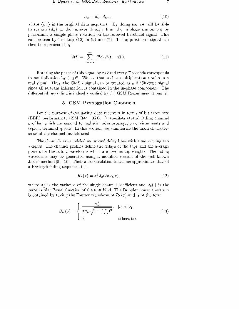
a Rayleigh fading sequence, i.e.,
Rh(�) = �2hJ0(2��D�); (12)
where �2h is the variance of the single channel coe�cient and J0(�) is thezeroth order Bessel function of the �rst kind. The Doppler power spectrum
is obtained by taking the Fourier transform of Rh(�) and is of the form
SH(�) =
8><>:
�2h
��D
q1� ( �
�D)2; j�j < �D
0; otherwise:
(13)
8 Facta Universitatis ser.: Elect. and Energ. vol. 12, No.2 (1999)
The range over which SH(�) is non-zero is known as the Doppler spread of
the channel. The maximum Doppler shift, also referred to as the Doppler
frequency, is given by �D = v � fc=c, where v is the terminal speed, fc is the
carrier frequency and c is the speed of light.
It is customary to consider three basic channel models for simulations
of the GSM system at fc = 900 MHz: the Hilly Terrain (HTx) model, the
Typical Urban (TUx) model and the Rural Area (RAx) model. Each model
is used for simulations of a given terminal speed (denoted by x in the channel
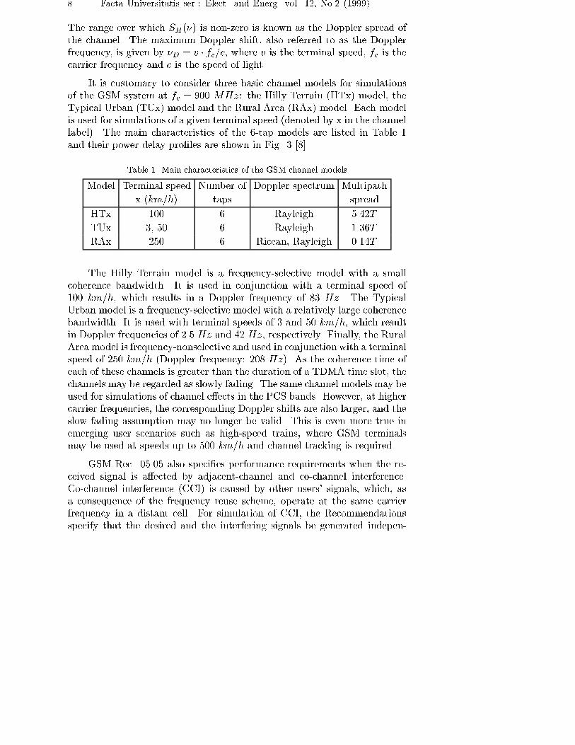
label). The main characteristics of the 6-tap models are listed in Table 1
and their power delay pro�les are shown in Fig. 3 [8].
Table 1. Main characteristics of the GSM channel models
Model Terminal speed Number of Doppler spectrum Multipath
x (km=h) taps spread
HTx 100 6 Rayleigh 5.42T
TUx 3, 50 6 Rayleigh 1.36T
RAx 250 6 Ricean, Rayleigh 0.14T
The Hilly Terrain model is a frequency-selective model with a small
coherence bandwidth. It is used in conjunction with a terminal speed of
100 km=h, which results in a Doppler frequency of 83 Hz. The Typical
Urban model is a frequency-selective model with a relatively large coherence
bandwidth. It is used with terminal speeds of 3 and 50 km=h, which result
in Doppler frequencies of 2.5 Hz and 42 Hz, respectively. Finally, the Rural
Area model is frequency-nonselective and used in conjunction with a terminal
speed of 250 km=h (Doppler frequency: 208 Hz). As the coherence time of
each of these channels is greater than the duration of a TDMA time slot, the
channels may be regarded as slowly fading. The same channel models may be
used for simulations of channel e�ects in the PCS bands. However, at higher
carrier frequencies, the corresponding Doppler shifts are also larger, and the
slow fading assumption may no longer be valid. This is even more true in
emerging user scenarios such as high-speed trains, where GSM terminals
may be used at speeds up to 500 km=h and channel tracking is required.
GSM Rec. 05.05 also speci�es performance requirements when the re-
ceived signal is a�ected by adjacent-channel and co-channel interference.
Co-channel interference (CCI) is caused by other users' signals, which, as
a consequence of the frequency reuse scheme, operate at the same carrier
frequency in a distant cell. For simulation of CCI, the Recommendations
specify that the desired and the interfering signals be generated indepen-
B. Bjerke et al: GSM Data Receivers: An Overview 9
−5 0 5 10 15 20 25−30
−25
−20
−15
−10
−5
0
5
10
t (us)A
ve. R
elat
ive
Pow
er (
dB)
HTx
−5 0 5 10 15 20 25−30
−25
−20
−15
−10
−5
0
5
10
t (us)
Ave
. Rel
ativ
e P
ower
(dB
)
TUx
−5 0 5 10 15 20 25−30
−25
−20
−15
−10
−5
0
5
10
t (us)
Ave
. Rel
ativ
e P
ower
(dB
)
RAx
Fig. 3. Power delay pro�les for the HTx, TUx and RAx channel models
dently but subjected to the same propagation pro�le. Adjacent-channel
interference (ACI) is generated by users operating at adjacent carrier fre-
quencies in the same cell as the desired user. For simulation of ACI, GSM
Rec. 05.05 speci�es that only the desired signal be subjected to multipath
propagation, while the interferer can be a static GMSK signal with a given
carrier frequency.
The design of the data receiver is highly dependent on the channel
characteristics. For instance, the channel memory directly determines the
number of states needed in the MLSE and the length of linear and decision
feedback equalizers. The fading rate of the channel is the deciding factor for
whether to choose a fully adaptive receiver structure or one that adapts on
a once-per-time slot (block adaptive) basis.
4. The Data Receiver
4.1. Receiver Function
The GSM data receiver function can be broken down into three tasks,
namely acquisition, synchronization and demodulation. Some tasks are ac-
tivated only at certain instances, while others are active practically all the
time while the mobile station is on. This fact results in di�erent requirements
for the various tasks of the data receiver [11].
10 Facta Universitatis ser.: Elect. and Energ. vol. 12, No.2 (1999)
In the acquisition mode, the data receiver must be able to continuously
process the expected received signal to allow the mobile station to lock on
to the infrastructure. In the synchronization mode, the data receiver must
be able to set all parameters of the mobile such that it can communicate
in synchronism. The accuracy with which these parameters are determined
largely dictates how quickly the mobile can start communicating e�ectively
with the infrastructure.
In the normal demodulation mode, the main task of the data receiver is
to provide reliable received symbols (bits), either as hard or soft estimates,
to the rest of the system. In addition to equalization, it must be able to
perform frequency and timing synchronization (tracking), matched �ltering
and bad frame indication. Depending on the partitioning between RF and
digital baseband functions, other tasks may include received signal strength
indication (RSSI), DC o�set compensation, etc. In this paper, we will focus
on the normal demodulation mode of the receiver, assuming that acquisition
and synchronization have been achieved.
4.2. Design Considerations
There are several design considerations with every GSM data receiver
development. These include
� receiver structure (baseband interface and signal format),
� equalization technique for data detection,
� soft versus hard decision channel decoding,
� bad frame indication (BFI) mechanism,
� phase synchronization and bit timing,
� rate of adaptation of the receiver,
� channel impulse response (CIR) estimation, and
� implementation and architectural issues, mainly software/hardware par-
titioning of the receiver functions.
The data receiver structure is highly dependent on the signal format
provided for baseband processing. Regardless of the radio architecture (sin-
gle, double or direct conversion), the baseband signal is usually represented
using in-phase and quadrature components (I & Q). The alternative receiver
structure is based on log-polar representation of the signal, where the sig-
nal magnitude is obtained via RSSI, and the signal phase is independently
B. Bjerke et al: GSM Data Receivers: An Overview 11
sampled [12]. Keeping in mind the characteristics of the GMSK modulation,
two di�erent solutions may be applied in the case of I & Q representation,
resulting in di�erent signal processing structures. In the so-called parallel
receiver, both I and Q signal components are processed (after matched �lter-
ing), while in the serial receiver, only the in-phase component is processed,
as signal de-rotation, accomplished by multiplying the incoming signal by
the sequence (�j)n, e�ectively moves all relevant information into the in-
phase component. This simpli�es the realization of the equalizer, as complex
arithmetic can be replaced by real arithmetic [13].
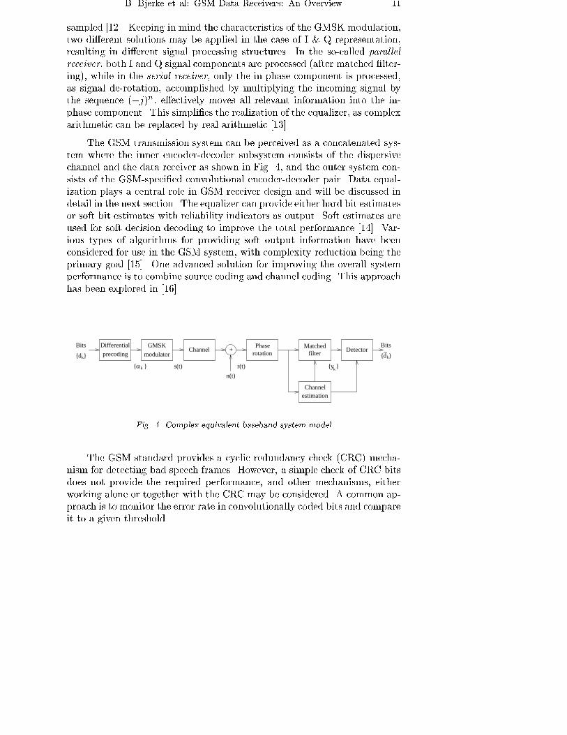
The GSM transmission system can be perceived as a concatenated sys-
tem where the inner encoder-decoder subsystem consists of the dispersive
channel and the data receiver as shown in Fig. 4, and the outer system con-
sists of the GSM-speci�ed convolutional encoder-decoder pair. Data equal-
ization plays a central role in GSM receiver design and will be discussed in
detail in the next section. The equalizer can provide either hard bit estimates
or soft bit estimates with reliability indicators as output. Soft estimates are
used for soft decision decoding to improve the total performance [14]. Var-
ious types of algorithms for providing soft output information have been
considered for use in the GSM system, with complexity reduction being the
primary goal [15]. One advanced solution for improving the overall system
performance is to combine source coding and channel coding. This approach
has been explored in [16].
+
n(t)
Differential
precodingGMSK
modulatorChannel
Phaserotation
Matchedfilter
Detector
Channelestimation
α }{
{dk
k
}
{yk}s(t) r(t)
Bits
{d~k}
Bits
Fig. 4. Complex equivalent baseband system model
The GSM standard provides a cyclic redundancy check (CRC) mecha-
nism for detecting bad speech frames. However, a simple check of CRC bits
does not provide the required performance, and other mechanisms, either
working alone or together with the CRC may be considered. A common ap-
proach is to monitor the error rate in convolutionally coded bits and compare
it to a given threshold.
12 Facta Universitatis ser.: Elect. and Energ. vol. 12, No.2 (1999)
Initial frequency and timing synchronization are acquired using fre-
quency correction and synchronization bursts, respectively. Depending on
the channel dynamics and overall receiver design, phase and bit timing track-
ing can be performed jointly with equalization, or separately. The equalizer
adaptation rate depends on the channel Doppler spread, as discussed in Sec-
tion 3.
The channel estimation is performed by cross correlating the middle
part of the received burst (after phase rotation) with the original training
sequence. The eight 26-bit training sequences de�ned in the GSM Recom-
mendations - one for each user in the frame - have been optimized with
respect to their correlation properties. The cross correlation between dif-
ferent training sequences is negligibly low. The autocorrelation functions
have narrow peaks and low sidelobes within �5 bit intervals of the zero-lagelement. The cross correlation operation used to estimate the channel im-
pulse response therefore yields a peaked sequence which may also be used
to extract timing information from the received burst. More speci�cally, the
starting point of the burst can be computed from the position of the correla-
tion peak. The channel estimate itself is utilized in calculating the matched
�lter and equalizer tap coe�cients as well as sequence detector metrics.
Several implementation and architectural issues are addressed in
Section 5.
4.3. Data Equalization
For development of equalizers, the complex equivalent baseband system
shown in Fig. 4 is considered. As seen in the �gure, the data receiver
consists of a phase rotator (in case of a serial receiver), a channel estimator,
a matched �lter and a detector (equalizer). We assume that the channel
is slowly time-varying and that it may be regarded as approximately �xed
throughout the duration of a burst. Computing the channel estimate only
once per burst is therefore considered su�cient.
We assume that the transmitted signal is adequately modeled by the
linear approximation introduced in Section 2,
s(t) �1X
n=�1
jndnP (t� nT ); (14)
regardless of the method actually used to generate it. Sampling the in-
phase component of this signal after it has undergone a phase rotation will
directly restore the original data bits fdng. The received signal is passed
B. Bjerke et al: GSM Data Receivers: An Overview 13
through a matched �lter whose impulse response is matched to the response
of the overall complex channel. The overall channel includes the transmitter
pulse, the actual channel and the impulse response of a predetection �lter for
rejection of out-of-band interference and noise. Consequently, the received
signal r(t) may be represented as
r(t) =
1Xn=�1
dnh(t� nT ) + n(t); (15)
where h(t) is the complex impulse response of the overall channel and n(t) is
additive white Gaussian noise (AWGN). The combination of phase rotation
and matched �ltering performed on this signal produces an output whose
in-phase component contains su�cient information to estimate the original
data sequence fdng. All subsequent processing at the receiver is done in
the discrete time domain. Given the normalized bandwidth, BT = 0:3, it is
su�cient to sample the received signal once per symbol interval. A discrete-
time version of the matched �lter h�(�t) is adaptively set up once per burst,based on the estimate of the overall discrete-time channel impulse response.
It is assumed that the ISI extends over a maximum of (Lc + 1) symbol
intervals, so that a discrete-time channel estimate with (Lc + 1) coe�cients
is su�cient.
The received signal, sampled at the symbol rate, may be represented as
rk =
LcXn=0
(j)ndnhk�n + �k; (16)
where fdng is the original information sequence, fhng represents the complexoverall impulse response of the channel and f�kg is AWGN with variance
N0=2. The output of the matched �lter is represented by
yn =
LcXi=�Lc
xidn�i + �n; (17)
where fxig are the samples of the impulse response of the cascade of fhng andits matched �lter fh�
�ng taken at the rate 1=T and �k denotes the additive
colored noise sequence at the output of the matched �lter.
In the following sections, we will summarize several equalizer/detector
structures and emphasize elements that are characteristic for their applica-
tion in the GSM system.
14 Facta Universitatis ser.: Elect. and Energ. vol. 12, No.2 (1999)
4.3.1. Sequence Estimation Techniques
With the serial receiver structure, the real parts of the samples fykgform a set of su�cient statistics for computation of the (real) metrics used in
the optimal maximum likelihood sequence estimator (MLSE). The maximum
likelihood estimates of the data symbols fdng are those that maximize the
simpli�ed recursive metrics
Ln(dn) = Ln�1(dn�1) + Re
(dn(yn �
LcXk=1
dn�kxk)
); (18)
which suggests the use of the Viterbi algorithm [17]. This MLSE takes
as input the output of the matched �lter and takes into account that the
noise is colored. Since the discrete-time impulse response estimate made
available by the channel estimator has length (Lc+1), the number of states
in the Viterbi algorithm is 2Lc . This approach is the most common in GSM
systems. However, the complexity of the MLSE grows exponentially with Lcand di�erent sub-optimal sequence estimation schemes have been considered
[18], including reduced-state sequence estimation [19], sequential detection
[20] and the M-algorithm [21].
Alternatives to sequence estimation have also been explored, and promi-
nent among them are the decision feedback equalizer (DFE) and a related
technique known as nonlinear data directed detection (NDDE).
4.3.2. Decision Feedback Equalization
The conventional DFE consists of a transversal feedforward �lter, a
feedback �lter and a decision device. Its computational complexity is a
linear function of the channel dispersion, (Lc+1), which is also the length of
the channel estimate. The binary decisions of the threshold detector are used
as inputs to the feedback �lter. In applying the DFE to the baseband model
of the GSM system, we optimize the feedforward and feedback coe�cients
using the MMSE criterion. This optimization is performed once per received
burst, based on the channel estimate and using as input the matched �ltered
received signal (with colored noise). The feedforward and feedback �lters
both have symbol-spaced taps.
The input to the decision device is given by
dn =
K1Xj=�K1
afj yn�j �K2Xj=1
abj~dn�j ; (19)
B. Bjerke et al: GSM Data Receivers: An Overview 15
where 2K1 + 1 and K2 are the number of feedforward and feedback coef-
�cients, respectively, and ~dn denotes the decision made on the symbol dn.
Using the MMSE criterion, the feedforward coe�cients af = [af
�K1� � � afk1 ]
T
are found to be
af = x0(0)R�1 (20)
were
R =
0Xk=�K1�L
x(k)x0(k) +N0 [x(�K1) � � �x(0) � � �x(K1)] ; (21)
and
x(k) = [xk+K1: : : xk�K1
]T (22)
As before, fxng represents the samples of the autocorrelation of fhng.The prime denotes the conjugate transpose. The feedback coe�cients
ab = [ab1 � � � abK2]T are given by
ab = aTf x(j); j = 1; 2; : : : ;K2; (23)
where K2 = K1 + L.
The solution for the DFE coe�cients is valid for complex-valued input
signals. When adopting a serial receiver structure, the input signals are
real-valued and the �ltering operation is performed using the real parts of
the coe�cients only. Initially, the DFE operates in a training mode, where
known training bits are used as inputs to the feedback �lter. At the end of
the training sequence, the DFE goes into a decision-directed mode, where
actual bit decisions are fed back.
Speci�c modi�cations for the GSM system rely on complexity reduction
via repositioning of the feedforward coe�cients, depending on the channel
pro�le [22]. Although nonlinear techniques are predominant in GSM equal-
izer realizations, linear equalizers have been considered as well [23].
4.3.3. Data Directed Estimation
A nonlinear data directed estimator for fading and multipath HF chan-
nels was proposed in [24] and further discussed in [25]. In contrast to the
DFE and other symbol-by-symbol equalization methods, the NDDE is based
on direct estimation of blocks of data, using a channel estimate which is as-
sumed to be valid throughout the duration of a burst. The NDDE has been
16 Facta Universitatis ser.: Elect. and Energ. vol. 12, No.2 (1999)
modi�ed to facilitate its use in the TDMA frame structure of the GSM sys-
tem, where the data blocks are longer and there is a midamble rather than
the pre- and postambles typically found in HF systems [26].
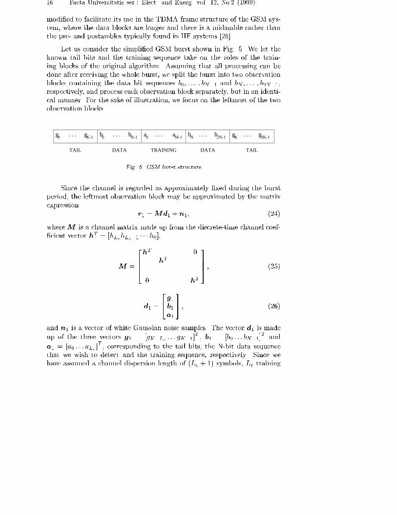
Let us consider the simpli�ed GSM burst shown in Fig. 5. We let the
known tail bits and the training sequence take on the roles of the train-
ing blocks of the original algorithm. Assuming that all processing can be
done after receiving the whole burst, we split the burst into two observation
blocks containing the data bit sequences b0; : : : ; bN�1 and bN ; : : : ; b2N�1,
respectively, and process each observation block separately, but in an identi-
cal manner. For the sake of illustration, we focus on the leftmost of the two
observation blocks.
gK g2K-1. . .bN b2N-1. . .a0 . . . aM-1b . . . bN-10K-1g. . .0g
DATA TAILTRAININGDATATAIL
Fig. 5. GSM burst structure
Since the channel is regarded as approximately �xed during the burst
period, the leftmost observation block may be approximated by the matrix
expression
r1 =Md1 + n1; (24)
where M is a channel matrix made up from the discrete-time channel coef-
�cient vector hT = [hLchLc�1 � � � h0],
M =
2664hT 0
hT
. . .
0 hT
3775 ; (25)
d1 =
24 g1b1a1
35 ; (26)
and n1 is a vector of white Gaussian noise samples. The vector d1 is made
up of the three vectors g1 = [gK�Lc : : : gK�1]T, b1 = [b0 : : : bN�1]
Tand
a1 = [a0 : : : aLc ]T, corresponding to the tail bits, the N-bit data sequence
that we wish to detect and the training sequence, respectively. Since we
have assumed a channel dispersion length of (Lc + 1) symbols, Lc training
B. Bjerke et al: GSM Data Receivers: An Overview 17
symbols on either side of the data block need to be considered. The channel
matrix can be split up into three submatrices Mg , Mb and Ma, where Mg
and Ma are (N + Lc)� Lc matrices, while Mb is an (N + Lc)�N matrix
[26]. Thus, [29] may be written as
r1 =Mgg1 +Mbb1 +Maa1 + n1: (27)
Assuming that the estimated channel coe�cients are valid throughout the
duration of the burst, the ISI due to the two training blocks can be recon-
structed and subtracted from the observation block, resulting in the vector
c1 given by
c1 = r1 �Mgg1 �Maa1 =Mbb1 + n1: (28)
The data bits may then be estimated. Minimization of the mean squared
error MSE = Ehjb1 � b1j2
iyields the MMSE solution for the data vector
b1:
b1 = (R� +N0
2I)�1z1; (29)
where R� =M 0
bMb is an N �N matrix with elements
Ri;j = xj�i, i; j = 0; : : : ; N � 1; (30)
and fxng represents the autocorrelation sequence of the channel coe�cients
fhng, as before. The vector z1 corresponds to the output of the discrete-timematched �lter using c1 as input, and is given by
z1 =M 0
bc1: (31)
The solution [34] di�ers from the one found in [24] and [25] in that it also
takes into account the noise in the system. The equation can be solved
e�ciently using the generalized Levinson-Durbin algorithm.
Up to this point, we have described a linear data directed estimator.
A nonlinear recursive estimator was proposed in [24] to improve upon the
performance of the linear algorithm on channels with spectral nulls. On such
channels, the MSE for the edge symbols b0 and bN�1 can be considerably
smaller than the MSE for the symbols in the middle. b0 and bN�1 therefore
are the two most reliable symbol estimates. In the NDDE, only these two are
kept for decision in the �rst stage, while the other estimates, b1; : : : ; bN�2are discarded. The soft estimates b0 and bN�1 are quantized and treated
as additional training symbols. The corresponding ISI is then reconstructed
and subtracted from the vector z1, whose size has been reduced by two.
18 Facta Universitatis ser.: Elect. and Energ. vol. 12, No.2 (1999)
The symbols left in the block are estimated once again using the reduced-
size version of [34], and the procedure is repeated recursively until all symbol
have been detected.
As was the case for the MLSE and the DFE, a serial receiver structure
is adopted in which the real part of the input signal provides a su�cient
statistic for detecting the symbols. As a consequence, only the real parts of
R and z are used, although the above derivation is valid for complex-valued
input signals.
4.3.4. Performance Results
In this section, we summarize the performance in terms of BER vs.
signal-to-noise ratio of the equalizers/detectors considered in the previous
sections, based on results presented in [27]. The overall receiver BER was
computed by averaging the individual BERs for the transmitted bursts. The
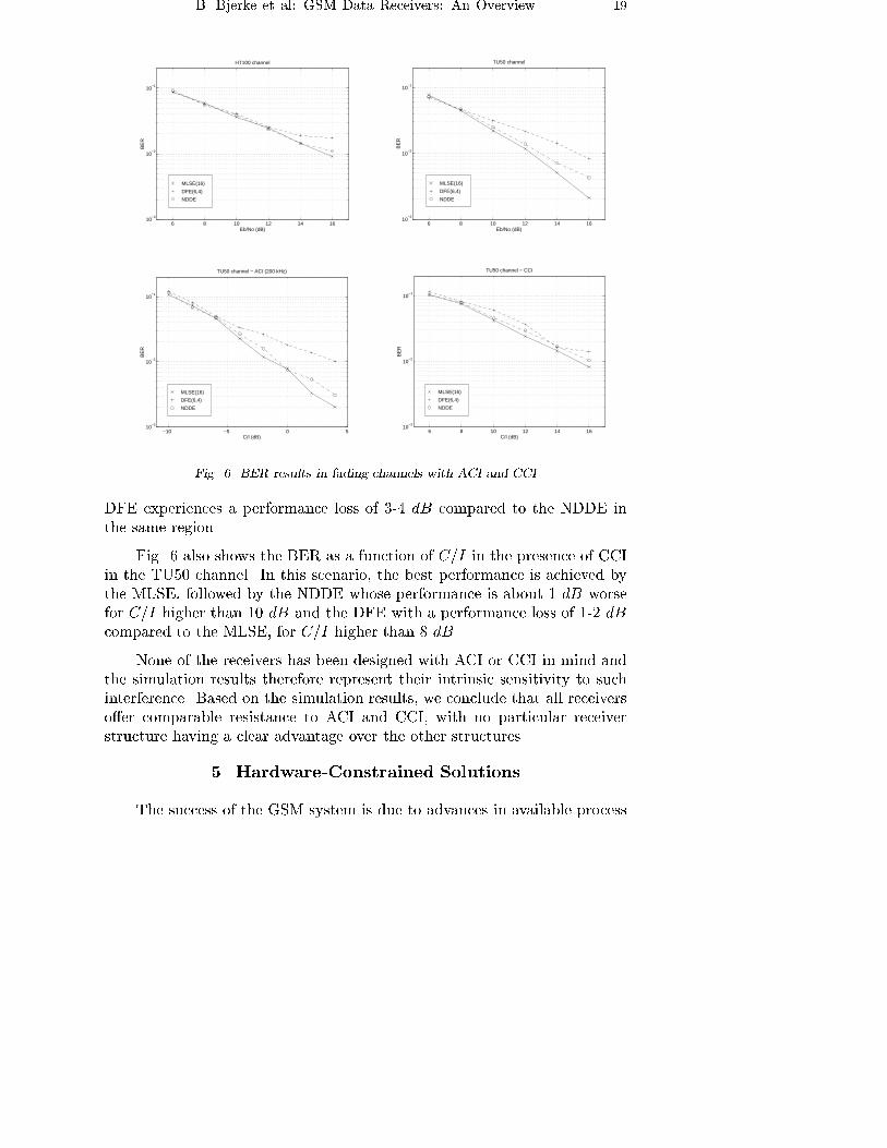
plots in Fig. 6 re ect results obtained by averaging over 700 bursts. Results
for the HT100 channel indicate that for Eb=N0 in the range 6 to 12 dB,
the three detectors have similar performance. For Eb=N0 higher than 12
dB, the NDDE performs almost as well as the MLSE, while the DFE ex-
periences a performance loss of 1-2 dB. In the TU50 channel the NDDE
experiences a performance loss of 1 dB for Eb=N0 higher than 10 dB, com-
pared to the MLSE. On the other hand, the NDDE outperforms the DFE
by approximately 2 dB for Eb=N0 higher than 10 dB.
The simulation results indicate that the NDDE and the DFE detectors
perform just as well as the MLSE in the simulated fading channels, in the
Eb=N0 range from 6 to 10 dB. This is the region of practical interest for
GSM systems. For Eb=N0 higher than 10 dB, the NDDE experiences a
modest performance loss compared to the MLSE, while the DFE experiences
a somewhat larger loss.
The performance of the three detectors was also evaluated in the case
where the received signal is a�ected by adjacent-channel and co-channel in-
terference. For evaluation of the performance in the presence of ACI, TU50
propagation conditions were simulated. The receiver front end contains an
eight-pole Butterworth predetection �lter with a one-sided 3 dB bandwidth
of 110 kHz. The interfering signal is a static signal, i.e., it does not expe-
rience fading multipath propagation, and it is assumed to be continuously
modulated by a random bit stream, as suggested in [8]. We observe that the
performance of the MLSE and the NDDE is quite similar, with the MLSE
having an advantage of about 1 dB for C=I higher than �4 dB, while the
B. Bjerke et al: GSM Data Receivers: An Overview 19
6 8 10 12 14 1610
−3
10−2
10−1
Eb/No (dB)
BE
R
HT100 channel
DFE(6,4)
NDDE
MLSE(16)
6 8 10 12 14 1610
−3
10−2
10−1
Eb/No (dB)
BE
R
TU50 channel
MLSE(16)
DFE(6,4)
NDDE
−10 −5 0 510
−3
10−2
10−1
C/I (dB)
BE
R
TU50 channel − ACI (200 kHz)
MLSE(16)
NDDE
DFE(6,4)
6 8 10 12 14 1610
−3
10−2
10−1
C/I (dB)
BE
R
TU50 channel − CCI
MLSE(16)
NDDE
DFE(6,4)
Fig. 6. BER results in fading channels with ACI and CCI
DFE experiences a performance loss of 3-4 dB compared to the NDDE in
the same region.
Fig. 6 also shows the BER as a function of C=I in the presence of CCI
in the TU50 channel. In this scenario, the best performance is achieved by
the MLSE, followed by the NDDE whose performance is about 1 dB worse
for C=I higher than 10 dB and the DFE with a performance loss of 1-2 dB
compared to the MLSE, for C=I higher than 8 dB.
None of the receivers has been designed with ACI or CCI in mind and
the simulation results therefore represent their intrinsic sensitivity to such
interference. Based on the simulation results, we conclude that all receivers
o�er comparable resistance to ACI and CCI, with no particular receiver
structure having a clear advantage over the other structures.
5. Hardware-Constrained Solutions
The success of the GSM system is due to advances in available process

20 Facta Universitatis ser.: Elect. and Energ. vol. 12, No.2 (1999)
technologies as well as advances in system integration and architectural ap-
proaches. The entire signal chain of the wireless transceiver from antenna
to microphone can be implemented using very large scale integrated (VLSI)
circuits. Today, all baseband processing elements, of which the data receiver
is the most important, are exclusively fabricated using submicron CMOS
technology. Rapid evolution towards smaller geometries provides a technol-
ogy path to lower power consumption and higher performance, as well as
lower cost of components [28]. Digital CMOS technology, including hard-
ware logic in various forms from stand-alone modules to co-processors units,
and digital signal processing (DSP) technology are the main success factors
in baseband processor implementation.
Technological advances have resulted in increased computational capa-
bility of DSP chips, larger memory available on-chip and various techniques
for software/hardware co-design. This ultimately leads to highly integrated
chip-sets for GSM, which meet all the relevant commercial requirements of a
worldwide standard, namely low price, low power consumption, a high degree
of manufacturability and high performance. Recent commercial trends point
to migration towards single-chip baseband solutions that integrate a DSP
core with embedded microprocessors, memory, specialized logic and mixed
signal elements such as baseband and audio analog-to-digital and digital-
to-analog converters [29]. Such highly integrated platforms o�er many new
opportunities for the design of data receivers.
In any implementation of the data receiver and its most computationally
intensive element - the equalizer - the following tradeo�s have to be taken
into account:
� exible programmable DSP realizations versus �xed hardwired applica-
tion speci�c integrated circuit (ASIC) solutions,
� power consumption,
� complexity versus available computational power,
� processing constraints due to real-time requirements.
Programmable DSP solutions have clear advantages in terms of exibil-
ity, possible upgrades and future-proof solutions. The possibility of o�ering
di�erent DSP based receiver modules leaves the decision on the data receiver
structure to the �nal integration stage, where complexity can be traded with
performance, power consumption and execution time. Enhanced DSP in-
struction sets, in which the number of cycles needed to perform a given task
is continuously decreasing, address functions that are basic to the operation
B. Bjerke et al: GSM Data Receivers: An Overview 21
of the data receiver. Sequence estimators, in particular the MLSE, are found
to be implementation bottlenecks of GSM data receivers. One of the most
common enhancements in DSP instruction sets is add-compare-select (ACS)
capability , which is essential for implementation of the Viterbi algorithm,
both for equalization and decoding of convolutional codes. Programmable
logic solutions are also used for equalizer implementation, but mainly for
prototyping [30]. It is also worth mentioning that recent developments in
software radios [31] include solutions where exible programmable data re-
ceivers may even be ported to general purpose processors. However, from a
commercial standpoint, such solutions are still not mature.
Power consumption is directly related to the choice of implementation
method, and usually is inverse to the level of exibility. Since the Viterbi
algorithm is commonly benchmarked, direct comparisons of silicon area and
power consumption are possible [28]. Regardless of process technology, hard-
ware solutions bene�t from an order of magnitude lower power consumption,
obtained at the expense of larger silicon area (5-7 times depending on pro-
cess geometry) and lower exibility. Migrating to smaller process geometries
and lower power supply voltages, the di�erence in silicon area is decreasing
at a higher rate than the di�erence in power consumption, but the area
requirements are still signi�cant.
Reductions in complexity, power consumption and execution time can
be achieved in two ways: at the algorithmic level by selecting a suitable
equalizer solution, or at the architectural level by exploiting hardware/ soft-
ware co-design techniques. Complexity reductions at the algorithmic level
include the use of suboptimal techniques for sequence estimation or decision-
feedback equalization. At the architectural level, data receiver functions
can be partitioned between the DSP and specialized accelerators or co-
processors. This approach is mainly used to improve the e�ciency of MLSE
data receiver realizations, since it preserves a certain exibility while re-
ducing the power consumption and DSP computational load. The Viterbi
algorithm may be implemented using a dedicated co-processor used for both
equalization and decoding. At the same time, the architecture may be aug-
mented by modi�cations in the algorithms, in particular in the computation
of soft decisions in sequence estimators [11], [32].
To summarize, the implementation of the data receiver is subject to a
number of tradeo�s, primarily related to applications. Looking at current
solutions for portable and base station GSM receivers there is less di�erence
in functionality and exibility, while di�erences in power consumption are
still signi�cant.
22 Facta Universitatis ser.: Elect. and Energ. vol. 12, No.2 (1999)
6. Data Receiver Enhancements
The evolution of the GSM system towards a new generation of wireless
systems has profound e�ect on the development of the data receiver and sev-
eral focus areas can be identi�ed. A new radio interface for high speed data
transmission known as EDGE has been developed as part of GSM Phase
2+. The dominant e�ect of CCI on the performance has triggered increased
interest in CCI suppression techniques in TDMA systems, coinciding with
theoretical developments in multiuser detection and the creation of a uni�ed
theoretical framework for joint detection in TDMA and CDMA systems [33].
New services have also motivated researchers to explore the applicability of
blind equalization algorithms to GSM, both for reception in fading channels
and CCI suppression. Finally, adaptive antenna arrays have been considered
from di�erent viewpoints: diversity reception, space-division multiple-access
and CCI reduction. It is important to note that strict categorization of
the new developments within these focus areas is di�cult. Often, new so-
lutions provide a functionality based on combinations of signal processing
approaches (e.g., joint detection based on blind algorithms using array ob-
servations).
6.1. Enhanced Data Rates for GSM Evolution (EDGE)
The Enhanced Data rates for GSM Evolution (EDGE) work item within
GSM Phase 2+ focuses on enhancements in the radio interface to accomo-
date high speed data services while reusing as much of the physical layer
as possible [34]. It has also been adopted for IS-136 evolution by the Uni-
versal Wireless Communications Consortium (UWCC) in the USA. EDGE
developments impact radio requirements while enabling new services in GSM
networks. The improvement of GSM data rates in EDGE is achieved by us-
ing higher level modulation formats (e.g., 8-PSK) without expanding the
bandwidth beyond the current 200 kHz. In addition, combining several
time slots can result in a user rate of 384 kbit=s. EDGE supports both cir-
cuit switched and packet data services. A number of technical issues that
can impact the design of the data receiver are discussed in EDGE: various
pulse shapes for 8-PSK modulation, the burst format of the 8-PSK burst,
modulation format and length of training sequences, link adaptation, new
channel coding techniques and a slow frequency hopping option [35]. The de-
velopment of data receivers in EDGE is most likely going to follow the same
evolutionary steps as those of the original data receivers for GSM. Results
reported thus far indicate that the most promising contender is a suboptimal
sequence estimator which uses a seven tap channel estimate, with complex-
B. Bjerke et al: GSM Data Receivers: An Overview 23
ity approximately four times higher than the complexity of the standard
16-state Viterbi equalizer for GMSK [35].
6.2. Suppression of Co-Channel Interference
One of the most important factors limiting the capacity of GSM sys-
tems is co-channel interference generated in neighbouring cells that use the
same carrier frequency. Several techniques have been adopted in current
GSM systems to minimize the problem of CCI, such as discontinuous trans-
mission (DTX), power control and slow frequency hopping [36]. However,
GSM data receivers have not been developed taking into account CCI and,
thus, represent suboptimal designs from a theoretical point of view. Indeed,
evaluations of known data receiver structures focus on performance degra-
dation due to CCI, and provide CCI reference levels which in turn determine
frequency reuse [37].
High capacity, low reuse cellular systems may be designed by increas-
ing the robustness of the data receiver in CCI environments. Several signal
processing methods can be applied in the GSM scenario for interference can-
cellation, as summarized in [36]:(1) multiuser (joint) detection, (2) blind or
semi-blind methods, (3) adaptive array processing techniques, or (4) combi-
nations of the above.
While the conventional GSM receiver treats CCI as additive noise,
multiuser detectors explore the deterministic nature of the CCI, exploit-
ing knowledge of the modulation format and training sequences used by the
interferers. Multiuser techniques have been developed primarily to combat
intra-cell interference; however, in GSM they are used to combat inter-cell
CCI. Since the number of nearby cochannel interferers is rather small, most
likely a dominant interferer exists. Simulation results presented in [36] in-
dicate that the dominant interferer is above 5 dB with a 30% probability
when all mobile terminals are taken into consideration. Considering only
the mobiles that experience poor reception quality, i.e., where C/I<9 dB,
this probability increases to 60%. The 5 dB level of the dominant interferer
corresponds approximately to the 3 dB gain obtained when using multiuser
detection [36], so it is concluded that 60% of the mobile terminals experi-
encing poor reception quality can achieve a 3 dB gain with a more advanced
receiver design.
While uplink reception may bene�t from antenna array gains, downlink
reception is usually limited to using a single antenna at the mobile terminal.
Assuming that only a single antenna is available for GMSK signal reception,
several algorithms for joint detection in the case of a dominant interferer have
24 Facta Universitatis ser.: Elect. and Energ. vol. 12, No.2 (1999)
been analyzed for use in GSM, based on joint MLSE as well as joint symbol-
by-symbol MAP detection [36]. Simulation results indicate that depending
on the base station activity, the gain relative to a conventional receiver
varies between 4 and 9 dB at a BER of 1%. It has been demonstrated
that joint detection of the two strongest interfering signals gives only 1 dB
improvement compared to cancellation of the dominant interferer. Other
relevant techniques include sequence detection with reduced complexity 38
and per-survivor processing algorithms [39]. There are several GSM-speci�c
aspects of joint detection.
� Joint detection implies that the CIR of the desired and co-channel sig-
nals can be estimated by joint channel estimation via training sequences.
� No more than seven training sequences can be used for joint estimation
in omnidirectional cells. The performance of existing training sequences
in GSM is good; a possible improvement of 1.3 dB can be achieved by
using new 20-bit sequences (requires a change in the standard).
� Base station synchronization, which allows synchronous reception of
the desired signal and CCI, should be established. In the case of burst
synchronous transmission, training sequences can be received simulta-
neously, and by taking advantage of good cross-correlation properties,
joint channel estimation can be carried out e�ciently. Base station
synchronization implies the use of GPS or monitoring of neighbouring
BCCH carrier synchronization sequences.
� Even when base stations are synchronized, di�erent propagation delays
may cause unacceptable asynchronism. The use of microcells can mini-
mize such delays. An analysis presented in [36] shows that a cell radius
of 1 km causes negligible loss in joint detection performance, while a
cell radius of 5 km results in a loss of about 2 dB.
� Identi�cation of the dominant interferer on a burst-by-burst basis is
bene�cial, especially when frequency hopping is used since CCI can
change from burst to burst. This identi�cation can be achieved as part
of the channel estimation, taking advantage of the di�erent training
sequences.
In a GSM network, the potential gains resulting from joint detection
include lower required transmission power and enlarged cell sizes for mo-
biles with joint detection capability. Dedicated carriers can be allocated to
mobiles with joint detection receivers, providing enhanced quality or higher
bit rates to their users. GSM microcell systems can fully bene�t from this
approach.
B. Bjerke et al: GSM Data Receivers: An Overview 25
6.3. Blind Equalization
Blind equalization and blind channel estimation have recently received
increased attention in the context of GSM, initially motivated by the pos-
sibility of reducing the overhead created by the training sequence. This
overhead can instead be used for other purposes such as channel coding [40].
One drawback is that bit synchronization, which is currently obtained from
the midamble containing the training sequence, would have to be obtained
by other means requiring additional processing.
As far as data receiver design is concerned, two major approaches have
been considered, namely blind channel estimation and blind channel equal-
ization. In the former, the channel is estimated blindly and the estimate is
then utilized by a standard equalizer. This is a blind analogy of the direct
approach in equalization, where the equalizer coe�cients are calculated from
the computed channel impulse response. In the latter approach, blind equal-
ization is used to recover the data sequence. This is analogous to the indirect
approach in equalization, where the equalizer coe�cients are computed and
updated based on the selected receiver optimization criterion.
In blind channel estimation, the idea is to derive a channel impulse
response estimate for the received signal without having access to the chan-
nel input signal. Two classes of algorithms have been studied for use in
GSM [40]: (1) higher order statistics (HOS), based on symbol rate sampling
and higher order cumulants, and (2) second-order cyclostationary statistics
(SOCS), based on fractional sampling (made possible by time diversity or
antenna diversity) and available excess bandwidth. The burst nature of GSM
limits the sample size that can be used for channel estimation to about 150.
A small sample size heavily a�ects the estimation performance when SOCS
is used, particularly when dealing with so-called singular channel classes.
Channels belonging to these classes can therefore not be identi�ed in this
way. On the other hand, the main obstacle for HOS-based approaches is the
requirement of obtaining low-error channel estimates from high-error esti-
mates of fourth-order cumulants. The algorithms that have been considered
for use in GSM include an eigenvector approach to blind identi�cation and
the w-slice algorithm [40]. Simulation results indicate that in the BER re-
gion of interest (on the order of one percent), data receivers based on MLSE,
using channel estimates obtained with blind algorithms, exibit losses of 1-2
dB as compared to non-blind schemes, depending on the propagation pro-
�le. In the CCI case, the relative di�erence between the blind and non-blind
approaches remain constant with increasing interference levels, although the
evaluation was carried out at C=I-levels greater than 10 dB, which is of
26 Facta Universitatis ser.: Elect. and Energ. vol. 12, No.2 (1999)
limited interest from a practical point of view.
As for blind equalization, several techniques have been considered for
use in GSM, including single-input multiple-output algorithms based on
derotation using both HOS and SOCS [41], SOCS-based blind equalization
[42] and probabilistic approaches [43]. These techniques su�er from several
shortcomings which preclude their application in commercial GSM systems:
low convergence speed, particularly in time-varying channels [42], consider-
able loss in required SNR in the BER region of interest [41], and increased
complexity compared to existing GSM data receiver structures [43].
A signi�cant potential has been identi�ed in the area of blind space-
time processing, especially in CCI environments. The application of blind
techniques can relax system requirements needed for e�cient joint detection
in GSM systems; multiple sensors provide not only diversity and interference
suppression capabilities, but also help avoid the problem of singular channels
in blind approaches. Several techniques have been proposed in this area,
indicating potential gains in the GSM framework [44], [43]. More results
are expected combining the blind space-time approaches with the partial
knowledge of signals that is available in GSM, such as �xed symbol rate,
constant modulus, �nite alphabet, known training sequence of the desired
user, etc.
6.4. Adaptive Antennas
As pointed out previously, adaptive antenna arrays, often referred to as
smart antennas, can be used to suppress co-channel interference and combat
multipath fading. The signal processing algorithms used involve both spatial
and temporal processing, and have therefore become known as space-time
processing algorithms. Adaptive arrays are primarily intended for use in
base station antennas, as the antenna size prevents their use in most mobile
terminals. We shall give a brief overview of the main ideas and methods
that are suitable for GSM, based partly on [45].
From a cellular operator's point of view, the two most important reasons
for introducing adaptive antennas are capacity increase and range extension
[46], [47]. These two factors directly a�ect the cost of deploying a network,
as they determine the density of base stations needed. Capacity increases
can be achieved by exploiting the spatial �ltering capability o�ered by the
array antenna. By generating a narrow beam in the direction of the mobile
terminal of interest, co-channel interference is reduced during both transmis-
sion and reception. During transmission, signal energy is concentrated in the
desired direction, while during reception, co-channel signals from other direc-
B. Bjerke et al: GSM Data Receivers: An Overview 27
tions are suppressed as a result of the antenna pattern. The actual capacity
gain can be realized through the use of two di�erent strategies [45]. The �rst
strategy is known as reduced cluster size (RCS). In a network where RCS
is employed, the spatial �ltering gain is used to reduce inter-cell co-channel
interference. As a result, the cluster size, i.e., the number of adjacent cells
with unique frequency allocation, can be reduced without compromising the
link quality. The second strategy is known as same cell reuse (SCR) or
space division multiple access (SDMA). Under this strategy, several mobile
terminals simultaneously use the same frequency channel in the same cell.
However, the physical separation of the terminals makes it possible to per-
form spatial �ltering and thus separate the co-channel signals. The capacity
increase is proportional to the number of mobile terminals that can share
the same frequency channel. The RCS scheme has been found to be the
more suitable of the two for use in GSM networks, as it can be implemented
without modifying the radio resource management protocols in the network.
It is well known that path loss increases with increasing frequency. A
practical consequence of this is that when deploying at network at, say, 1.8
GHz, more base stations are needed than at 900 MHz to obtain the same
coverage. Needless to say, this results in increased costs for the operator.
Base station antennas with high directivity, such as array antennas, have
extended range and can compensate for the increased path loss. While high
directivity can be accomplished with a �xed beam antenna system, adaptive
antenna arrays can, in addition, be used to track the position of the mobile
terminals within their sector. Measurement results indicate that signal-to-
noise ratio improvements and additional array diversity gain can be exploited
in DCS-1800 to support low-power mobile terminals or to double the cover-
age area [48].
In an adaptive array, the signals received by the multiple antennas are
weighted and combined to maximize the signal-to-interference-and-noise ra-
tio. With M antennas, an M -fold antenna gain can be achieved, as well as
an M -fold diversity gain, provided that the correlation of the fading among
the antennas is su�ciently low. Theoretically, N interferers can be cancelled
if M > N , leaving room for an (M � N)-fold diversity gain. This is true
even for multipath signals, as long as the delay spread is small. If the delay
spread is large, the array will treat the delayed versions of the signal as sep-
arate signals and resolve the multipath that way. Hence, the adaptive array
performs both spatial and temporal processing on the received signals. The
two most popular optimality criteria in space-time processing are the ML
criterion and the MMSE criterion.
28 Facta Universitatis ser.: Elect. and Energ. vol. 12, No.2 (1999)
The single-user space-time MLSE receiver for signals distorted by ISI
and noise represents an extension of the scalar MLSE discussed in Section
4.3.1. As before, a channel estimate is computed from the received midamble
that contains the training sequence. Joint channel estimation and data de-
tection can be performed if the channel varies with time during the reception
of a burst. The metrics can be reformulated to perform joint detection of the
desired signal and N co-channel interferers [38], [49]. As in the scalar case,
the space-time MLSE has a computational complexity that grows exponen-
tially with the channel memory. Various suboptimal schemes, designed to
reduce the complexity in a similar way as in the scalar case, have been pro-
posed. In the presence of CCI which itself has a delay spread, the space-time
MMSE receiver is a more attractive alternative [50]. This receiver weighs
and sums the antenna outputs to produce a �nal output that minimizes the
squared error between itself and the desired signal. The optimal weights are
computed from the received midamble. Hybrid schemes have also been pro-
posed, in which CCI and ISI reduction is performed in separate stages [51].
The general idea is to use a space-time MMSE �lter to suppress CCI and
take advantage of the spatial diversity, followed by an MLSE-type equalizer
for removing ISI and taking advantage of temporal diversity. Interference
rejection and combining algorithms have also explored for use in the GSM
scenario [52].
Numerous �eld-trials have been conducted for both downlink and up-
link scenarios [53], [46]. Measurements con�rm the expected link-level C/I
improvement. An antenna array at the base station achieves a 7-15 dB
improvement over a sector antenna in the uplink, depending on the algo-
rithm, and a 14-18 dB improvement in the downlink [46]. Using a circular
antenna array at the mobile terminal also leads to signi�cant improvements
[53]. Having in mind the signi�cant advantages of adaptive arrays, provisions
have been made for their inclusion in next-generation wireless networks. The
migration of adaptive antennas into existing networks has been outlined [54].
7. Concluding Remarks
As a result of its constant evolution, the GSM system is seen as a step-
ping stone for next generation wireless systems. As the system advances
towards the next generation, new concepts are foreseen, such as high speed
mobile multimedia, advanced addressing mechanisms and seamless roaming,
resulting in new requirements for the data receiver to support intelligent
and exible radio access technologies. New data receiver designs will very
likely include variable data rates, modulation adaptivity and advanced fad-
ing compensation. While the physical layer of wireless systems, in particular

B. Bjerke et al: GSM Data Receivers: An Overview 29
functions such as channel estimation and equalization, traditionally has pro-
vided fertile ground for statistical signal processing algorithms, the interde-
pendency of the data receiver and the overall system, including mitigation of
tra�c variation, support of di�erent quality of service requirements and in-
crease of system capacity, is becoming increasingly important. Data receiver
design will be tied not only to link level optimization, but also to overall sys-
tem level considerations such as spectrum and coverage e�ciency. On the
other hand, to achieve low cost terminals with increased computational ca-
pability, data receiver algorithms are becoming increasingly more intimately
connected to e�cient VLSI realizations. The challenges facing the devel-
opers of data receivers are numerous, and are likely to provide signi�cant
theoretical as well as practical advances.
REFERENCES
1. M. Mouly and B. Pautet: The GSM System for Mobile Communications. 1994.
2. A. Mehrota: GSM System Engineering., Artech House, 1997.
3. R. Steele: Mobile Radio Communications., Pentech Press, 1992.
4. Z. Zvonar, P. Jung, and K. Kammerlander Eds: GSM Evolution Towards 3rd
Generation Systems., Kluwer Academic Publishers, 1998.
5. P. A. Laurent: Exact and Approximate Construction of Digital Phase Modulations
by Superposition of Amplitude Modulated Pulses., IEEE Trans. on Commun., pp.
150{160, Feb. 1986.
6. P. Jung: Laurent's Representation of Binary Digital Continuous Phase Modulated
Signals with Modulation Index 1/2 Revisited., IEEE Trans. on Commun., pp. 221{
224, Feb./March/April 1994.
7. ETSI/GSM Recommendation 05.04.: Modulation., 1993.
8. ETSI/GSM Recommendation 05.05.: Radio Transmission and Reception., June
1993.
9. W. C. Jakes: Microwave Mobile Communications., Wiley, 1974.
10. P. Dent, G. E. Bottomley, and T. Croft: Jakes' Fading Model Revisited., IEE
Electronics Letters, pp. 1162{1163, June 1993.
11. M. K. Lee and Z. Zvonar: Soft-Decision MLSE Data Receiver for GSM Systems.,
Proceedings of the 8th MPRG Symp. on Wireless Personal Commun., pp. 179{190,
1998.
12. K. Okanoue, A. Ushirokawa, H. Tomita, and Y. Furuya: New MLSE Receiver
Free From Sample Timing and Input Level Controls., Proceedings of ICC 93, IEEE
Int. Conference on Commun., pp. 408{411, 1993.
13. J. Br�ndum: GSM Data Receivers - A Comparison., Technical Report R93-1002,
Institute for Electronic Systems, Aalborg University, Nov. 1993.
14. J. Hagenauer and P. Hoeher: A Viterbi Algorithm with Soft-Decision Outputs
and its Applications., Proceedings of Globecom 89, IEEE Global Commun. Confer-
ence, pp. 47.1.1{47.1.7, 1989.
30 Facta Universitatis ser.: Elect. and Energ. vol. 12, No.2 (1999)
15. B. Risl�w, T. Maseng, and O. Trandem: Soft Information in Concatenated
Codes. IEEE Trans. on Commun., pp. 284{286, March 1996.
16. J. Hagenauer: Source-Controlled Channel Decoding., IEEE Trans. on Commun.,
pp. 2449{2457, September 1995.
17. G. Ungerboeck: Adaptive Maximum-Likelihood Receiver for Carrier-Modulated
Data-Transmission Systems., IEEE Trans on Commun., pp. 624{636, May 1974.
18. G. Benelli, A. Garzelli, and F. Salvi: Simpli�ed Viterbi Processors for the
GSM Pan-European Cellular Communication System., IEEE Trans. on Vehic.
Tech., pp. 870{877, November 1994.
19. K. Wesolowski, R. Krenz, and K. Das: E�cient Receiver Structure for GSM
Mobile Radio., Int. Journal of Wireless Info. Networks, pp. 117{123, April 1996.
20. G. Zimmermann and W. Rupprecht: Soft-Decision Output in Sequential Detec-
tion Algorithms in Digital Mobile Radio Systems., In Proceedings of VTC 94, IEEE
Vehic. Tech. Conference, pp. 292{296, 1994.
21. P. Jung: Performance Evaluation of a Novel M-Detector for Coherent Receiver
Antenna Diversity in GSM-Type Mobile Radio Systems., IEEE Journal on Select.
Areas in Commun., pp. 80{88, January 1995.
22. P. A. M. Bun�e: A Low-E�ort DSP Equalization Algorithm for Wideband Digital
TDMA Mobile Radio Receivers. In Proceedings of ICC 91, IEEE International
Communications Conference, pp. 25.1.1{25.1.5, 1991.
23. J. Gu, J. Pan, Y. Watson, and S. Hall: An E�ective LMS Equalizer for the GSM
Chipset. In Proceedings of the 8th MPRG Symp. on Wireless Personal Commun.,
pp. 155{166, 1998.
24. F. H. Hsu: Data Directed Estimation Techniques for Single-Tone HF Modems.,
In Proceedings of MILCOM 85, IEEE Military Communications Conference, pp.
12.4.1{12.4.10, 1985.
25. S. N. Crozier, D. D. Falconer, and S. A. Mahmoud: Reduced Complex-
ity Short-Block Data Detection Techniques for Fading Time-Dispersive Channels.,
IEEE Trans. on Vehic. Tech., pp. 255{265, August 1992.
26. B. A. Bjerke, G. Proakis, M. K. Lee, and Z. Zvonar: A Comparison of Deci-
sion Feedback Equalization and Data Directed Estimation Techniques for the GSM
System., In Proceedings of ICUPC 97, IEEE Conference on Univ. Pers. Commun.,
pp. 993{998, 1997.
27. B. A. Bjerke, G. Proakis, M. K. Lee, and Z. Zvonar: A Comparison of GSM
receivers for Fading Multipath Channels with Adjacent- and Co-Channel Interfer-
ence., In Proceedings of PIMRC 98, IEEE Int. Symposium on Personal, Indoor and
Mobile Radio Commun., 1998.
28. F. Boutaud: VLSI Signal Processing Solutions for Wireless Communications:
TDMA versus CDMA., Kluwer Academic Publishers, 1997.
29. P. Jackson: Chips with Everything., Mobile Communications International, pp.
45{49, May 1998.
30. P. Jung and J. Blanz: Realization of a Soft Output Viterbi Equalizer Using Field
Programmable Gate Arrays., In Proceedings of VTC 93, IEEE Vehic. Tech. Con-
ference, pp. 625{628, 1993.

B. Bjerke et al: GSM Data Receivers: An Overview 31
31. T. Turletti and D. Tennenhouse: Complexity of a Software GSM Base Station.,
IEEE Commun. Mag., pp. 113{117, February 1999.
32. S. Ono, H. Hayashi, T. Tanaka, and N. Kondoh: A MLSE Receiver for the GSM
Digital Cellular System., In Proceedings of VTC 94, IEEE Vehic. Tech. Conference,
pp. 230{233, 1994.
33. S. Verdu: Multiuser Detection., Cambridge University Press, 1998.
34. ETSI/GSM Recommendation 10.59.: Enhanced Data Rates for GSM Evolution
(EDGE)., November 1998.
35. P. Schramm et al: Radio Interface Performance of EDGE, a Proposal for En-
hanced Data Rates in Existing Digital Cellular Systems., In Proceedings of VTC 98,
IEEE Vehic. Tech. Conference, pp. 1064{1068, 1998.
36. P. Ranta and M. Pukkila: Interference Suppression by Joint Demodulation of
Cochannel Signals., In GSM Evolution Towards 3rd Generation Systems, pp. 153{
186. Kluwer Academic Publishers, 1998.
37. M. Luise and R. Reggiannini: Performance Evaluation of an Adaptive GSM Re-
ceiver with Frequency-Selective Fading and Adjacent- and Co-channel Interference.,
Int. Journal of Digital and Analog Communication Systems, June 1993.
38. S. Wales: Technique for Cochannel Interference Suppression in TDMA Mobile
Radio Systems., IEE Proc. Commun., pp. 106{114, April 1995.
39. A. Polydoros and K. Chugg: Per-Survivor Processing (PSP)., In Wireless Com-
munications: TDMA vs CDMA. Kluwer Academic Publishers, 1997.
40. D. Boss et al: Is Blind Channel Estimation Feasible in Mobile Communication
Systems? A Study Based on GSM., IEEE Journal on Select. Areas in Commun.,
pp. 1479{1492, October 1998.
41. Z. Ding and G. Li: Single-Channel Blind Equalization for GSM Cellular Systems.,
IEEE Journal on Select. Areas in Commun., pp. 1493{1505, October 1998.
42. J. Altuna and B. Mulgrew: Comparison of Cyclostationary Blind Equalization
Algorithms in the Mobile Radio Environment., Int. Journal of Adapt. Control and
Signal Processing, pp. 267{282, May 1998.
43. J. R. Fonollosa, Z. Zvonar, J. A. R. Fonollosa, and J. Catala: Blind Mul-
tiuser Detection with Array Observations., Wireless Personal Commun., pp. 179{
196, June 1998.
44. A. van der Veen and A. J. Paulraj: Singular Value Analysis of Space-Time
Equalization in the GSM Mobile System., In Proceedings of ICASSP 96, IEEE Int.
Conference on Acoust., Speech and Signal Processing, pp. 1073{1076, 1996.
45. P. Mogensen et. al: Antenna Arrays and Space Division Multiple Access., In
GSM Evolution Towards 3rd Generation Systems, pp. 117{151. Kluwer Academic
Publishers, 1998.
46. S. Anderson et al: Ericsson/Mannesmann GSM Field-Trials With Adaptive An-
tennas., In Proceedings of VTC 97, IEEE Vehic. Tech. Conference, pp. 1587{1591,
1997.
47. S. Wells: Increasing the Capacity of GSM Cellular Radio Using Adaptive Anten-
nas., IEE Proceedings, Communications, pp. 304{310, October 1996.
32 Facta Universitatis ser.: Elect. and Energ. vol. 12, No.2 (1999)
48. M. Tangemann et al: Sensitivity Enhancements of GSM/DCS 1800 With Smart
Antennas., In Proceedings of EPMCC 97, Second European Personal Mobile Com-
munications Conference, pp. 87{94, 1997.
49. G. E. Bottomley and K. Jamal: Adaptive Arrays and MLSE Equalization., In
Proceedings of VTC 95, IEEE Vehic. Tech. Conference, pp. 50{54, 1995.
50. A. J. Paulraj and C. B. Papadias: Space-Time Processing for Wireless Commu-
nications., IEEE Signal Processing Magazine, pp. 49{83, November 1997.
51. J.-W. Liang, J.-T. Chen, and A. J. Paulraj: A Two-Stage Hybrid Approach for
CCI/ISI Reduction with Space-Time Processing. IEEE Communications Letters,
pp. 163{165, November 1997.
52. J. Karlsson and J. Heinegard: Interference Rejection and Combining for GSM.,
In Proceedings of ICUPC 96, IEEE Int. Conference on Univ. Pers. Commun., pp.
433{437, 1996.
53. P. Chevalier et al: Smart Antennas for the GSM System: Experimental Results
for Mobile Reception., In Proceedings of VTC 99, IEEE Vehic. Tech. Conference,
pp. 1572{1581, 1997.
54. F. Kronestedt and S. Andersson: Migration of Adaptive Antennas into Existing
Networks., In Proceedings of VTC 98, IEEE Vehic. Tech. Conference, pp. 1670{
1674, 1998.


![〇‥~(|ー…”〃〕/Ј〃 ”ー〔…/[~‥〆 ’ー]ー>〃 · 2013-02-05 · industrijske buke - ГЕiАeЕ fabЕike ceАeБЗa“, Facta universitatis - Series:](https://static.fdocuments.net/doc/165x107/5f0b25047e708231d42f11ae/aiiioefafif-afiia-affif-2013-02-05.jpg)
