
1 HVACR216 -Hydronics Expansion Tanks. 2 All fluids used in hydronic systems expand when heated....
44
1 HVACR216 -Hydronics Expansion Tanks
-
Upload
lynn-bennett -
Category
Documents
-
view
217 -
download
0
Transcript of 1 HVACR216 -Hydronics Expansion Tanks. 2 All fluids used in hydronic systems expand when heated....
1
HVACR216 -HydronicsHVACR216 -Hydronics
Expansion TanksExpansion Tanks
2
Expansion TanksExpansion Tanks
• All fluids used in hydronic systems expand when heated.
• This thermal expansion is an unavoidable and extremely powerful act of nature.
• All fluids used in hydronic systems expand when heated.
• This thermal expansion is an unavoidable and extremely powerful act of nature.
3
Expansion TanksExpansion Tanks
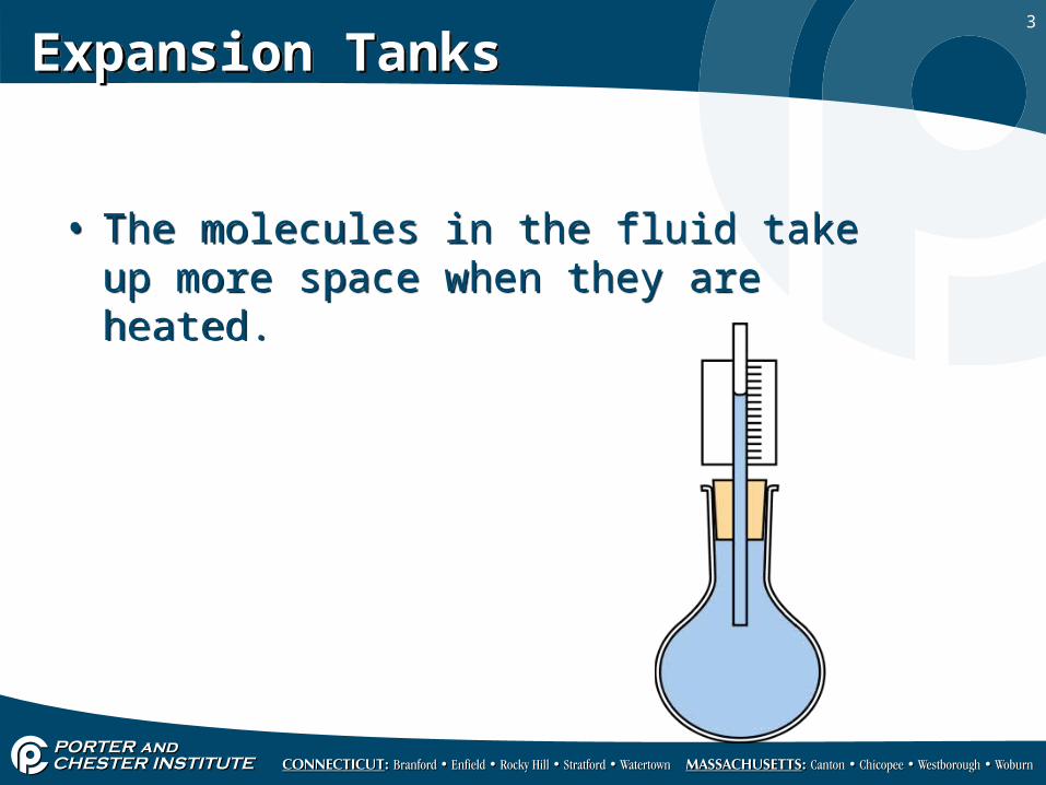
• The molecules in the fluid take up more space when they are heated.
• The molecules in the fluid take up more space when they are heated.
4
Expansion TanksExpansion Tanks
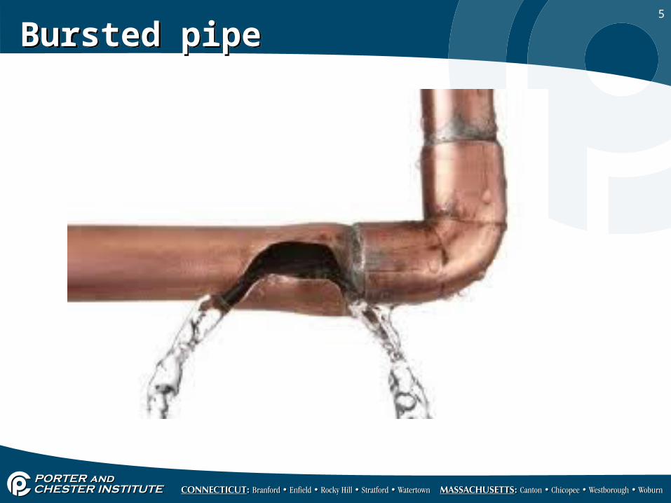
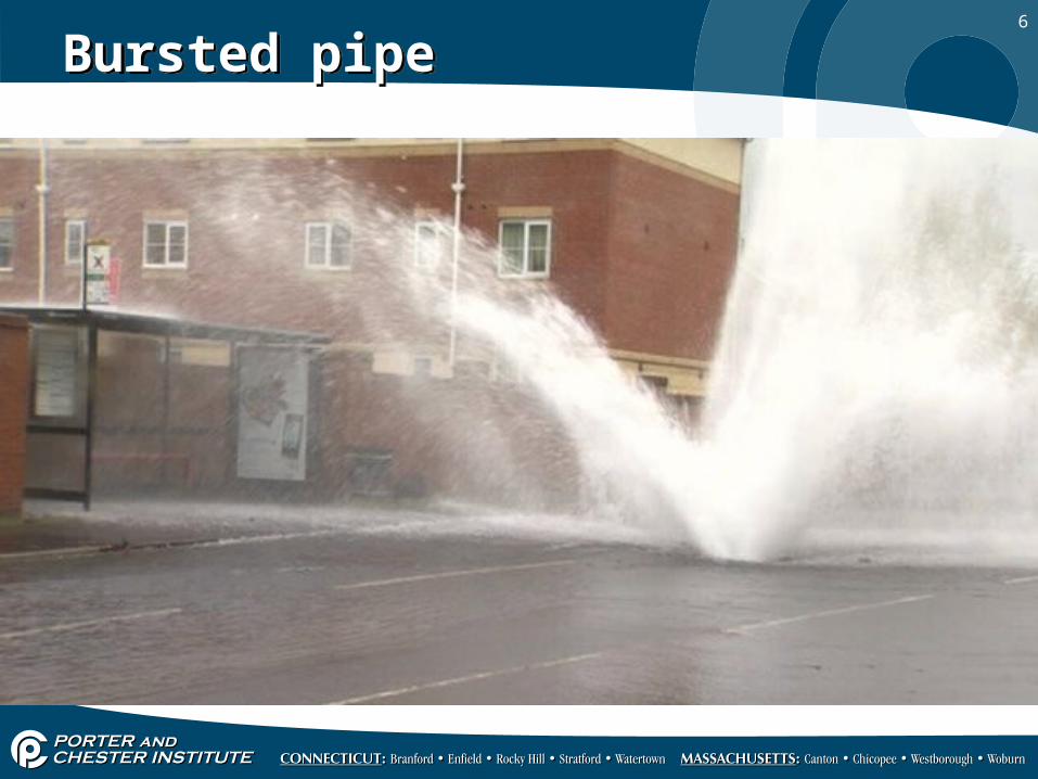
• Any container that is filled with a liquid and sealed from the atmosphere will experience an increase in pressure as the liquid is heated.
• If this pressure is allowed to build, the container will burst, and in some cases violently.
• Any container that is filled with a liquid and sealed from the atmosphere will experience an increase in pressure as the liquid is heated.
• If this pressure is allowed to build, the container will burst, and in some cases violently.
5
Bursted pipeBursted pipe
6
Bursted pipe Bursted pipe
7
Expansion TanksExpansion Tanks
• To prevent this from happening, all hydronic heating systems must be supplied with a means of accommodating the volume increase of the fluid as it is heated.
• The device that is commonly used in the closed loop hydronic system is the diaphragm expansion tank.
• To prevent this from happening, all hydronic heating systems must be supplied with a means of accommodating the volume increase of the fluid as it is heated.
• The device that is commonly used in the closed loop hydronic system is the diaphragm expansion tank.
8
Diaphragm expansion tankDiaphragm expansion tank
9
Diaphragm Expansion tankDiaphragm Expansion tank
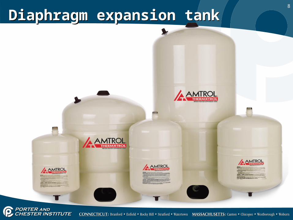
• A diaphragm type expansion tank has a flexible rubber membrane installed inside the tank. (diaphragm)
• On one side of this membrane, there is a captive air volume which is pre-pressurized by the manufacturer.
• A diaphragm type expansion tank has a flexible rubber membrane installed inside the tank. (diaphragm)
• On one side of this membrane, there is a captive air volume which is pre-pressurized by the manufacturer.
10
Diaphragm Expansion tankDiaphragm Expansion tank
11
Diaphragm Expansion tankDiaphragm Expansion tank
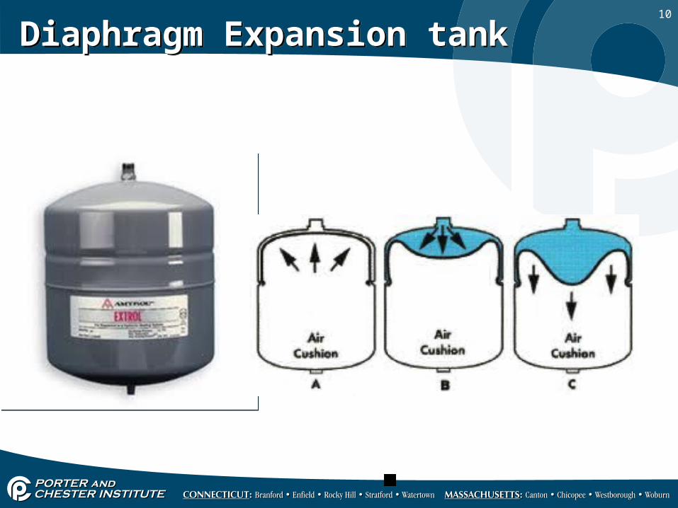
• On the opposite side is a chamber for accommodating the expanded volume of fluid.
• As more fluid enters the tank, the diaphragm flexes, allowing the air volume to be compressed.
• On the opposite side is a chamber for accommodating the expanded volume of fluid.
• As more fluid enters the tank, the diaphragm flexes, allowing the air volume to be compressed.
12
Diaphragm Expansion tankDiaphragm Expansion tank
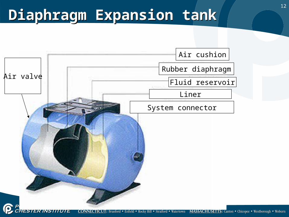
Air cushion
Rubber diaphragm
Fluid reservoirAir valve
System connector
Liner

13
Diaphragm type expansion tankDiaphragm type expansion tank
• Since the diaphragm separates the fluid from the air, the air can not be reabsorbed by the fluid.
• Diaphragm type expansion tanks do not have to be periodically drained to prevent water logging.
• Since the diaphragm separates the fluid from the air, the air can not be reabsorbed by the fluid.
• Diaphragm type expansion tanks do not have to be periodically drained to prevent water logging.
14
Diaphragm type expansion tankDiaphragm type expansion tank
• By avoiding water logging, the possibility of accelerated corrosion caused by addition of fresh water to make up for relief valve losses is no longer a factor.
• The air pressure in the tank can be adjusted to match the static pressure of the system.
• This is done before the system is filled with water.
15
Diaphragm type expansion tankDiaphragm type expansion tank
• No significant amount of water enters the tank until the system warms up resulting in a small lightweight tank.
• Because the air volume is captive, the tank can be theoretically mounted in any position.
• No significant amount of water enters the tank until the system warms up resulting in a small lightweight tank.
• Because the air volume is captive, the tank can be theoretically mounted in any position.
16
Diaphragm type expansion tankDiaphragm type expansion tank
• A properly sized diaphragm type expansion tank should reach a pressure of about 5 psi lower than the relief valve setting when the system reaches its maximum operating temperature.
• The safety margin prevents the relief valve from leaking just below its rated opening pressure.
• A properly sized diaphragm type expansion tank should reach a pressure of about 5 psi lower than the relief valve setting when the system reaches its maximum operating temperature.
• The safety margin prevents the relief valve from leaking just below its rated opening pressure.
17
Air side pressurizationAir side pressurization
• The proper air side pressurization is equal to the static fluid pressure at the inlet of the tank, plus an additional 5 psi allowance at the top of the system.
• The pressure on the air side diaphragm is always adjusted to the calculated value before the fluid is added to the system.
• The proper air side pressurization is equal to the static fluid pressure at the inlet of the tank, plus an additional 5 psi allowance at the top of the system.
• The pressure on the air side diaphragm is always adjusted to the calculated value before the fluid is added to the system.
18
Air side pressurizationAir side pressurization
• Adjusting the air pressure is done by adding or removing air through the Schrader Valve on the shell of the tank.
• A small air compressor or bicycle tire pump can be used when air is needed.
• Adjusting the air pressure is done by adding or removing air through the Schrader Valve on the shell of the tank.
• A small air compressor or bicycle tire pump can be used when air is needed.
19
Air side pressurizationAir side pressurization
• Proper air side pressure adjustment ensures the diaphragm will be fully expanded against the shell of the tank when the system is filled with fluid, but before it is heated.
• The failure to make this adjustment can result in the diaphragm being partially compressed by the fluids static pressure before any heating take place.
20
Pressure and temperature ratingsPressure and temperature ratings
• Expansion tanks have a maximum pressure and temperature ratings.
• This information is stamped on the label of the tank.
• Typical ratings are 60 psi and 240 degrees.
• Expansion tanks have a maximum pressure and temperature ratings.
• This information is stamped on the label of the tank.
• Typical ratings are 60 psi and 240 degrees.
21
Selection, mounting and serviceSelection, mounting and service
• Tanks are available in a wide range of shapes and sizes.
• Tanks with volumes of 1 gallon to 14 gallons are usually adequate for standard residential and light commercial hydronic systems.
• Tanks are available in a wide range of shapes and sizes.
• Tanks with volumes of 1 gallon to 14 gallons are usually adequate for standard residential and light commercial hydronic systems.
22
Selection, mounting and serviceSelection, mounting and service
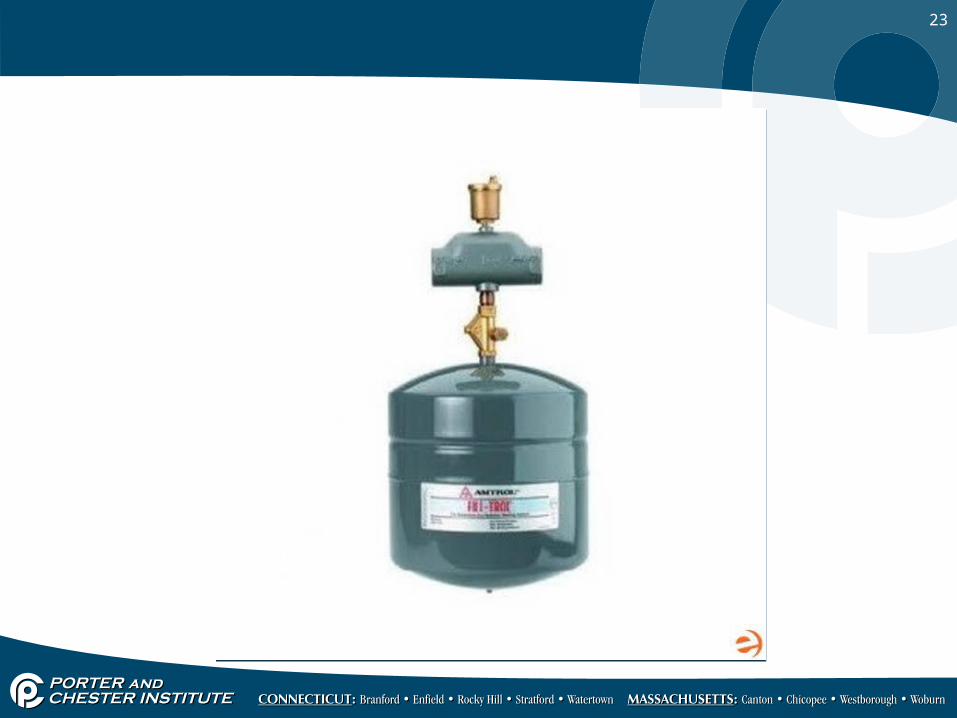
• These tanks are usually equipped with a ½” inch pipe connection from which they are designed to hang vertically.
• One common mounting method is to hang a diaphragm tank from the bottom of the system’s air separator.
• Many air separators have a ½” bottom tapping for this purpose.
• These tanks are usually equipped with a ½” inch pipe connection from which they are designed to hang vertically.
• One common mounting method is to hang a diaphragm tank from the bottom of the system’s air separator.
• Many air separators have a ½” bottom tapping for this purpose.
23
24
Selection, mounting and serviceSelection, mounting and service
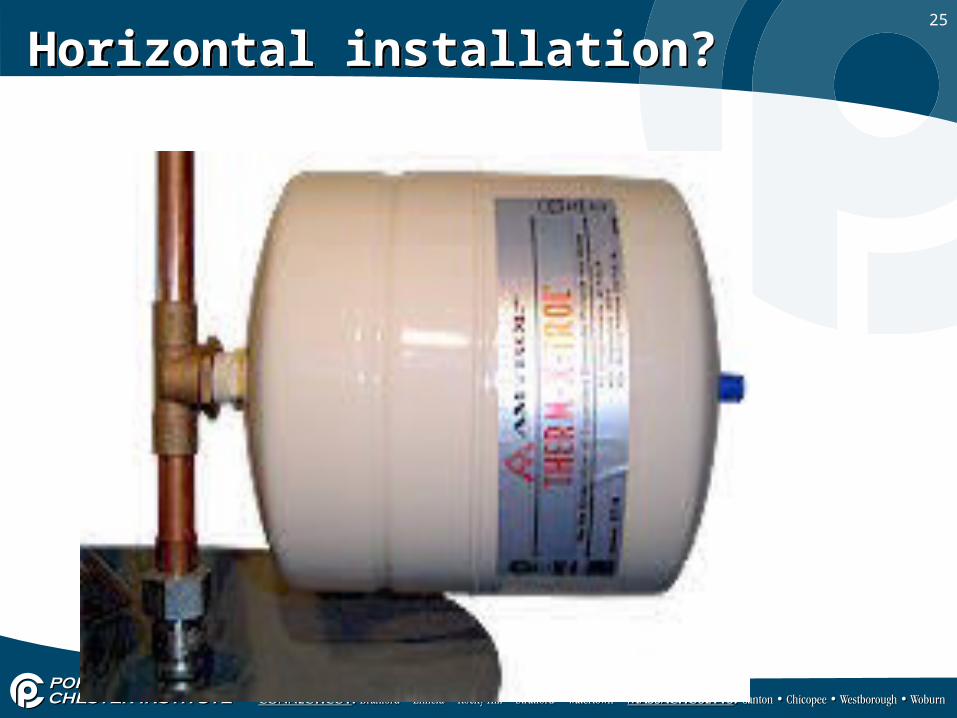
• Although the captive air volume would theoretically allow it to function in any orientation, there are other concerns to address whenever the tank is hung in any other position than vertically from its inlet connection.
• One is that air bubbles could form on the water side of this system and promote corrosion.
25
Horizontal installation?Horizontal installation?

26
Selection, mounting and serviceSelection, mounting and service
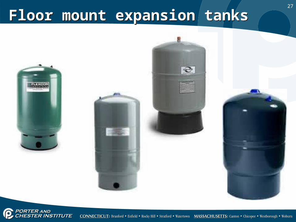
• When very large expansion tanks are required, floor mounted models are available.
• When very large expansion tanks are required, floor mounted models are available.
27
Floor mount expansion tanksFloor mount expansion tanks
28
Diaphragm expansion tank failureDiaphragm expansion tank failure
• Most diaphragm expansion tanks will retain their captive air volumes for decades.
• However, there is always the possibility that a diaphragm could leak.
• Most diaphragm expansion tanks will retain their captive air volumes for decades.
• However, there is always the possibility that a diaphragm could leak.
29
Diaphragm expansion tank failureDiaphragm expansion tank failure
• If this occurs, the tank will eventually lose it air and fill the system with fluid.
• Such a failure is easy to detect during a routine service check.
• Most complaints start with a “release of fluid from the pressure relief valve”.
• If this occurs, the tank will eventually lose it air and fill the system with fluid.
• Such a failure is easy to detect during a routine service check.
• Most complaints start with a “release of fluid from the pressure relief valve”.
30
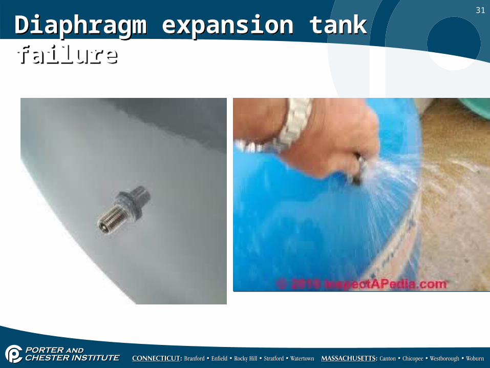
Diaphragm expansion tank failureDiaphragm expansion tank failure
• During the service check, simply press in on the schrader valve stem on the tanks air valve.
• If fluid comes out, the diaphragm has failed and the entire tank has to be replaced.
• During the service check, simply press in on the schrader valve stem on the tanks air valve.
• If fluid comes out, the diaphragm has failed and the entire tank has to be replaced.
31
Diaphragm expansion tank failureDiaphragm expansion tank failure
32
Diaphragm expansion tank failureDiaphragm expansion tank failure
• Tapping on the side of an intact diaphragm usually produces a hollow sound.
• If a “thud” is heard, most likely the diaphragm has failed and the tank is full of fluid.
• Tapping on the side of an intact diaphragm usually produces a hollow sound.
• If a “thud” is heard, most likely the diaphragm has failed and the tank is full of fluid.
33
Diaphragm expansion tank failure and replacementDiaphragm expansion tank failure and replacement
• Care should be taken when removing a failed expansion tank.
• First of all, the pressure on the tank must be reduced to zero psi or you will end up being showered with potentially very hot fluid.
• Secondly, a tank filled with fluid is surprisingly heavy!
• The expansion tank only gets hand tight. Do not tighten using a wrench.
34
Diaphragm expansion tank failure and replacementDiaphragm expansion tank failure and replacement
• As stated earlier, the air side pressure on the new expansion tank must be adjusted before fluid is allowed to enter the tank.
• As stated earlier, the air side pressure on the new expansion tank must be adjusted before fluid is allowed to enter the tank.

35
Diaphragm expansion tank sizing chartDiaphragm expansion tank sizing chart

36
Compression TankCompression Tank
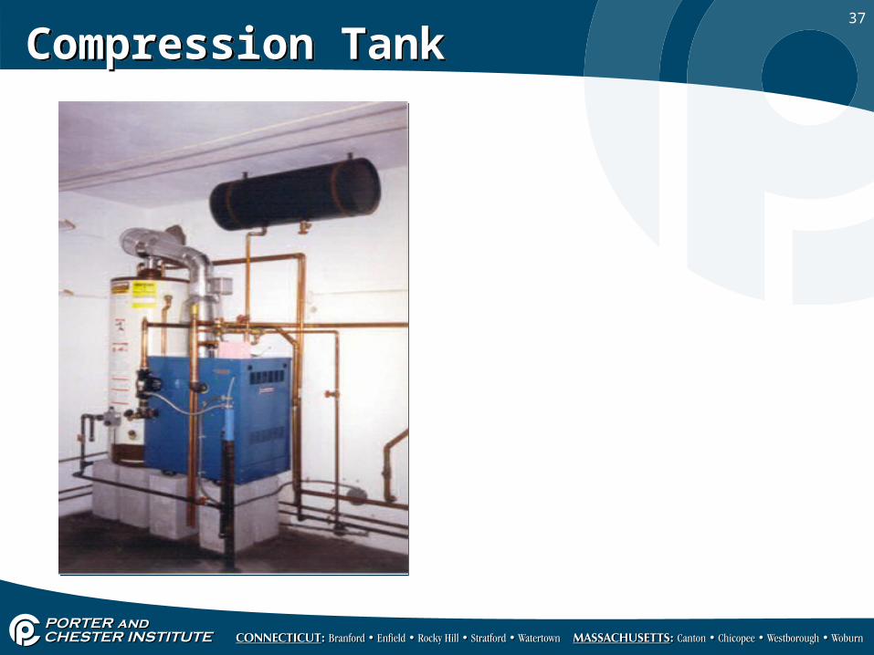
• Still in service today, but is slowly being replaced with the modern diaphragm tank, is the steel compression tank.
• These tanks were often hung from the underside of the floor joists just above the boiler.
• Still in service today, but is slowly being replaced with the modern diaphragm tank, is the steel compression tank.
• These tanks were often hung from the underside of the floor joists just above the boiler.
37
Compression TankCompression Tank
38
Compression TankCompression Tank
• The air in this type of tank is initially at atmospheric pressure.
• When the system is filled with fluid, the air is trapped in the top of the tank and partially compressed.
• The air in this type of tank is initially at atmospheric pressure.
• When the system is filled with fluid, the air is trapped in the top of the tank and partially compressed.
39
Compression TankCompression Tank
• As the water expands upon heating, additional fluid enters the tank, further compressing the air.
• An inherent problem with this design is that the air and water they contain are in direct contact with each other.
• As the water expands upon heating, additional fluid enters the tank, further compressing the air.
• An inherent problem with this design is that the air and water they contain are in direct contact with each other.
40
Compression TankCompression Tank
• As the fluid in the tank cools off, it has the ability to reabsorb some of the air back into solution.
• Upon reheating, the dissolved air will again come out of solution, but now on the system piping.
• As the fluid in the tank cools off, it has the ability to reabsorb some of the air back into solution.
• Upon reheating, the dissolved air will again come out of solution, but now on the system piping.
41
Compression TankCompression Tank
• Eventually this air will be removed by the air vents.
• An automatic feed water valve will then admit a small amount of water to make up for the lost air.
• Eventually this air will be removed by the air vents.
• An automatic feed water valve will then admit a small amount of water to make up for the lost air.
42
Compression TankCompression Tank
• The result of this cycle of venting and filling will eventually lead to a water logged tank.
• Which means the tank has become completely filled with water.
• The result of this cycle of venting and filling will eventually lead to a water logged tank.
• Which means the tank has become completely filled with water.
43
Servicing the Compression TankServicing the Compression Tank
• Compression tanks typically need to be drained and refilled two times a year to prevent the problems associated with water logging.
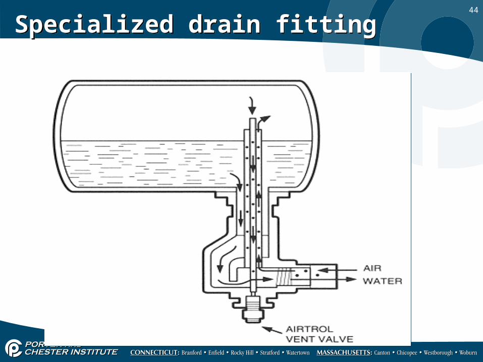
• Special drain valves that allow air to enter the tank the same time water is being drained are available for this purpose.
• Compression tanks typically need to be drained and refilled two times a year to prevent the problems associated with water logging.
• Special drain valves that allow air to enter the tank the same time water is being drained are available for this purpose.
44
Specialized drain fittingSpecialized drain fitting