1 Gustav Kirchhoff 1824-1887 German Physicist. Circuit Definitions Node – any point where 2 or...
25
1 KIRCHHOFF'S RULES CONTINUED Gustav Kirchhoff 1824-1887 German Physicist
-
Upload
orion-kemery -
Category
Documents
-
view
242 -
download
0
Transcript of 1 Gustav Kirchhoff 1824-1887 German Physicist. Circuit Definitions Node – any point where 2 or...

1
KIRCHHOFF'S RULES CONTINUED
Gustav Kirchhoff1824-1887
German Physicist
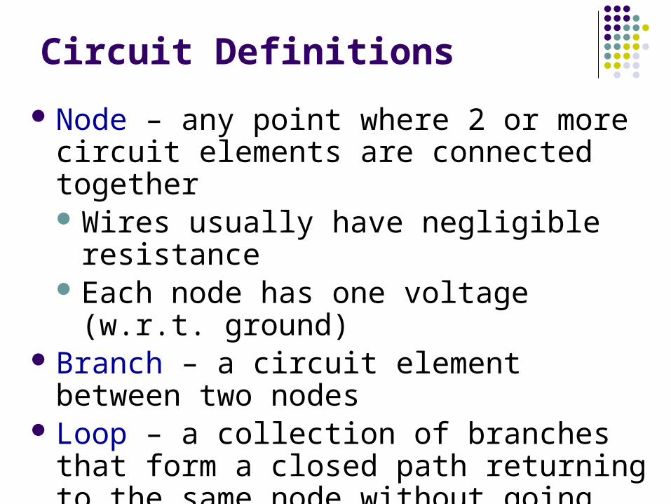
Circuit Definitions
Node – any point where 2 or more circuit elements are connected together Wires usually have negligible resistance Each node has one voltage (w.r.t. ground)
Branch – a circuit element between two nodes
Loop – a collection of branches that form a closed path returning to the same node without going through any other nodes or branches twice
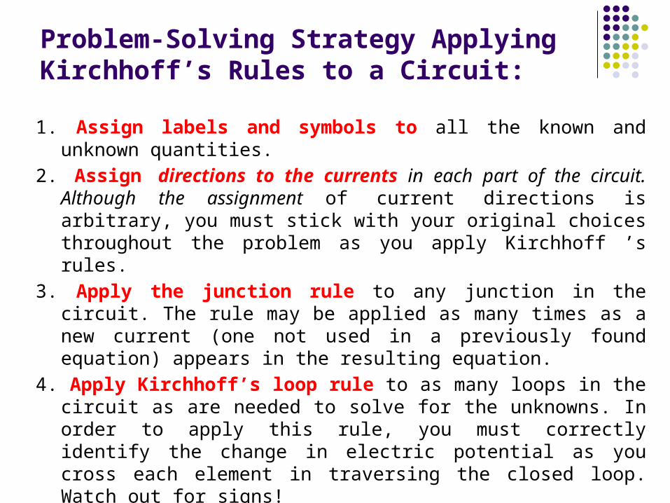
Problem-Solving Strategy Applying Kirchhoff’s Rules to a Circuit:
1. Assign labels and symbols to all the known and unknown quantities.
2. Assign directions to the currents in each part of the circuit. Although the assignment of current directions is arbitrary, you must stick with your original choices throughout the problem as you apply Kirchhoff ’s rules.
3. Apply the junction rule to any junction in the circuit. The rule may be applied as many times as a new current (one not used in a previously found equation) appears in the resulting equation.
4. Apply Kirchhoff’s loop rule to as many loops in the circuit as are needed to solve for the unknowns. In order to apply this rule, you must correctly identify the change in electric potential as you cross each element in traversing the closed loop. Watch out for signs!
5. Solve the equations simultaneously for the unknown quantities, using substitution or any other method familiar to the student.
6. Check your answers by substituting them into the original equations.
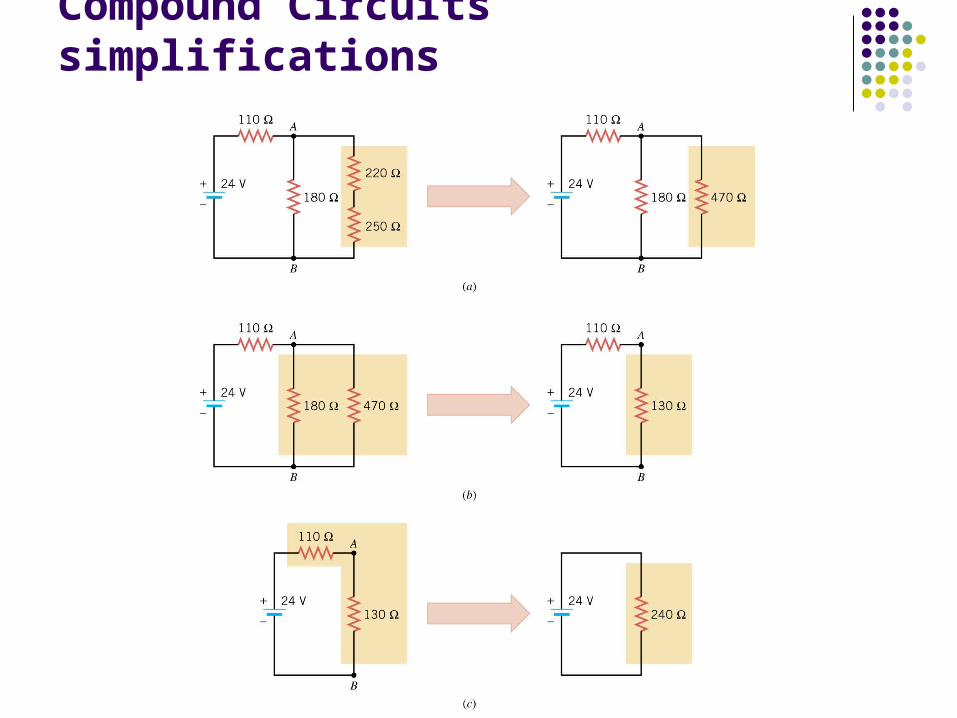
Compound Circuits simplifications
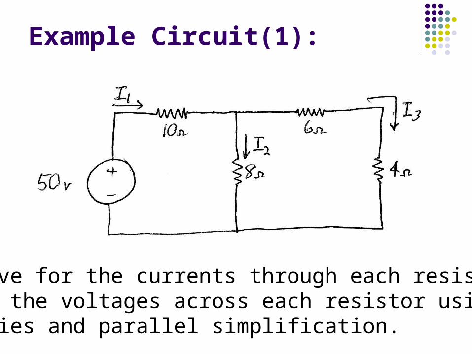
Example Circuit(1):
Solve for the currents through each resistor And the voltages across each resistor using Series and parallel simplification.
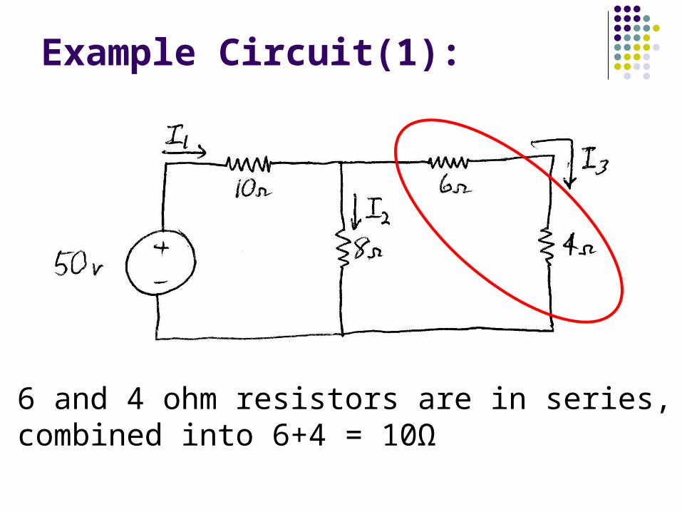
Example Circuit(1):
The 6 and 4 ohm resistors are in series, soare combined into 6+4 = 10Ω

Example Circuit(1):
The 8 and 10 ohm resistors are in parallel, soare combined into 8∙10/(8+10) =14.4 Ω
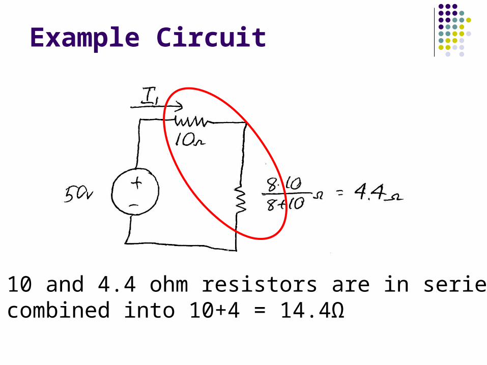
Example Circuit
The 10 and 4.4 ohm resistors are in series, soare combined into 10+4 = 14.4Ω
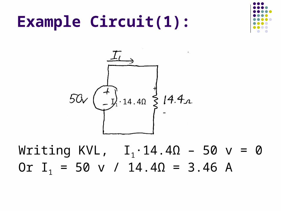
Example Circuit(1):
Writing KVL, I1∙14.4Ω – 50 v = 0Or I1 = 50 v / 14.4Ω = 3.46 A
+
I1∙14.4Ω -

Example Circuit(1):
If I1 = 3.46 A, then I1∙10 Ω = 34.6 vSo the voltage across the 8 Ω = 15.4 v
+34.6 v -
+ 15.4 v -
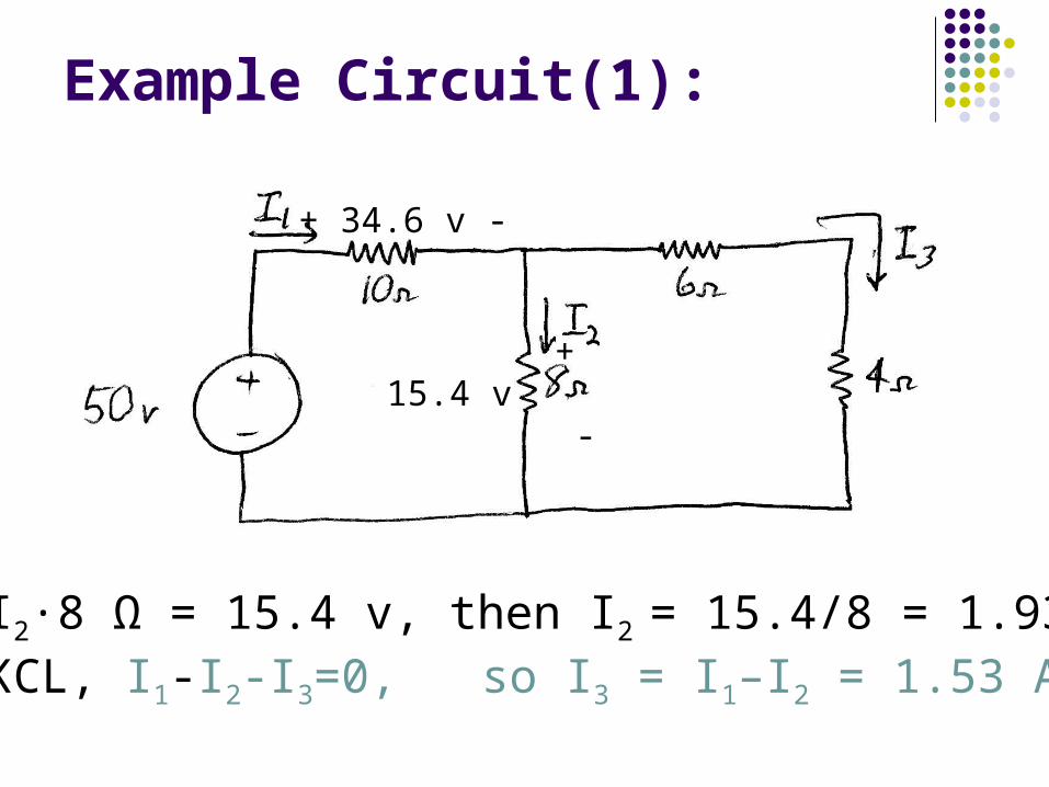
Example Circuit(1):
If I2∙8 Ω = 15.4 v, then I2 = 15.4/8 = 1.93 ABy KCL, I1-I2-I3=0, so I3 = I1–I2 = 1.53 A
+ 34.6 v -
+ 15.4 v -
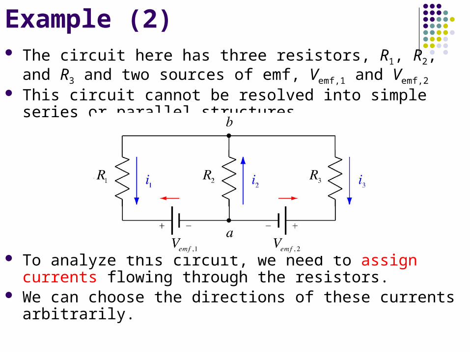
The circuit here has three resistors, R1, R2, and R3 and two sources of emf, Vemf,1 and Vemf,2
This circuit cannot be resolved into simple series or parallel structures
To analyze this circuit, we need to assign currents flowing through the resistors.
We can choose the directions of these currents arbitrarily.
Example (2)

At junction b the incoming current must equal the outgoing current
At junction a we again equate the incoming current and the outgoing current
But this equation gives us thesame information as theprevious equation!
We need more informationto determine the three currents – 2 more independent equations
Example (2):
i2 i1 i3
i1 i3 i2
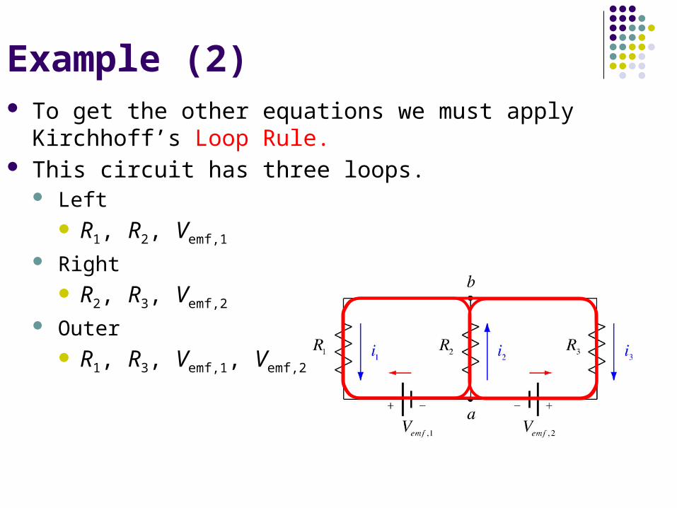
To get the other equations we must apply Kirchhoff’s Loop Rule. This circuit has three loops.
Left R1, R2, Vemf,1
Right R2, R3, Vemf,2
Outer R1, R3, Vemf,1, Vemf,2
Example (2)

Going around the left loop counterclockwise starting at point b we get
Going around the right loop clockwise starting at point b we get
Going around the outer loopclockwise startingat point b we get
But this equation gives us no newinformation!
Example - Kirchhoff’s Laws (4)
i1R1 Vemf ,1 i2R2 0 i1R1 Vemf ,1 i2R2 0
i3R3 Vemf ,2 i2R2 0 i3R3 Vemf ,2 i2R2 0
i3R3 Vemf ,2 Vemf ,1 i1R1 0
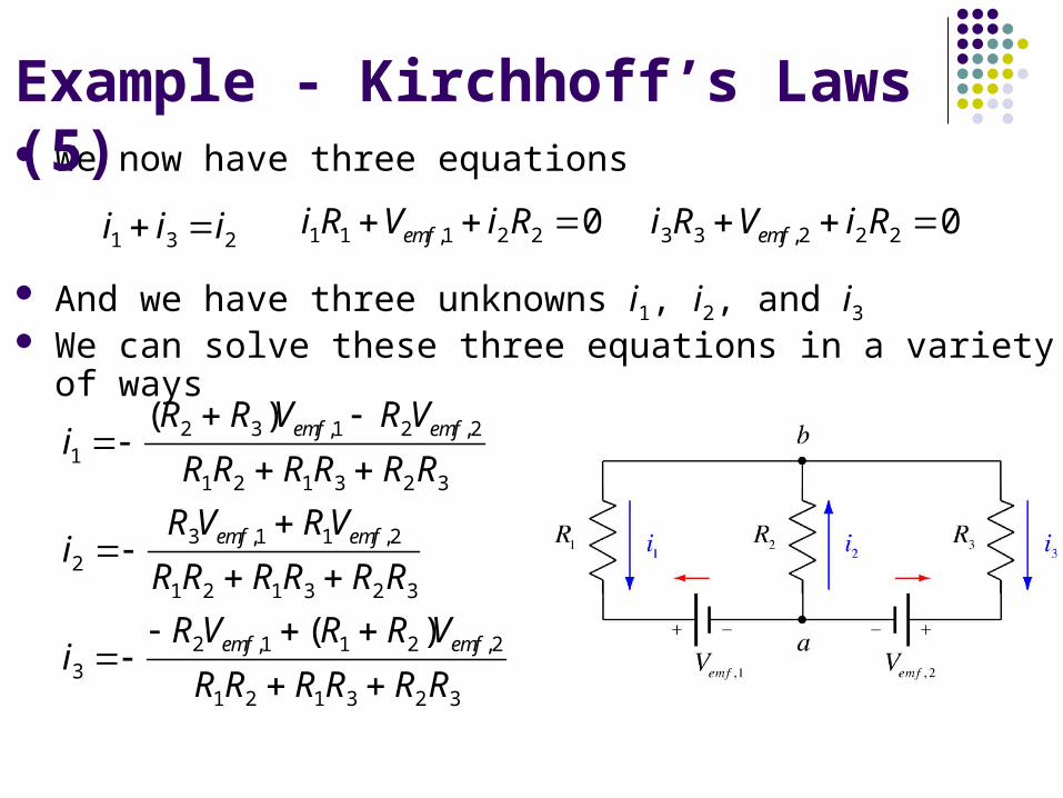
We now have three equations
And we have three unknowns i1, i2, and i3 We can solve these three equations in a variety of ways
Example - Kirchhoff’s Laws (5)
i1 i3 i2i1R1 Vemf ,1 i2R2 0 i3R3 Vemf ,2 i2R2 0
i1 (R2 R3)Vemf ,1 R2Vemf ,2
R1R2 R1R3 R2R3
i2 R3Vemf ,1 R1Vemf ,2
R1R2 R1R3 R2R3
i3 R2Vemf ,1 (R1 R2 )Vemf ,2
R1R2 R1R3 R2R3

Example (3):
Find the currents in the circuit shown in Figure by using Kirchhoff’s rules.
Solution:
Apply the junction rule to point c. I 1 is directed into the junction, I 2 and I 3 are directed out of the junction.
Select the bottom loop, and traverse it clockwise starting at point a, generating an equation with the loop rule:
Select the top loop, and traverse it clockwise from point c. Notice the gain across the 9.0- resistor, because it is traversed against the direction of the current
3I
2I
1I
0I
0 )I (9.0 -)I (4.0 -V 6.0
0
31
9.04.0bat
VVVV
0 )I (9.0 )I (5.0 -
0
32
9.05.0
VVV

Rewrite the three equations, rearranging terms anddropping units for the moment, for convenience:
Solve eq. 3 for I2 , substitute into eq. 1:
Substitute I3 back into eq. 3 to get I2 From eq.1
Substitute the latter expression Substitute I3 into eq. 2 to get I1
into eq. 2 and solve for I3
)3(0 9I 5I-
)2(09I4I6.0
)1(III
32
31
321
3232
32
I8.1II5
9I
-9I5I-
31331
321
I8.2III8.1I
III
A3.0I6.0I)92.11(
6.09I2.8I4
33
33
A54.0I7.25I
0 0.39 5I-
22
2
A83.0
3.054.0I
III
1
321
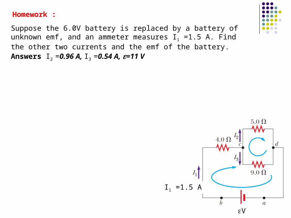
Homework :
Suppose the 6.0V battery is replaced by a battery of unknown emf, and an ammeter measures I1 =1.5 A. Find the other two currents and the emf of the battery.Answers I2 =0.96 A, I3 =0.54 A, e=11 V
eV
I1 =1.5 A
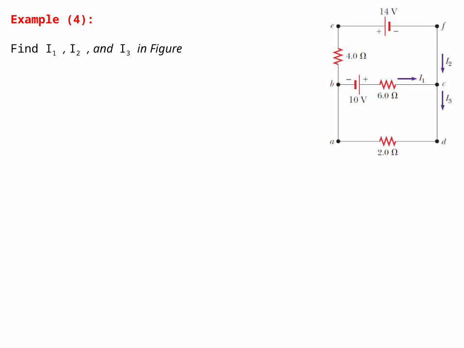
Example (4):
Find I1 , I2 , and I3 in Figure

2.5. What is the current through the 4- resistor in this circuit?
a) 0.67 A
b) 0.75 A
c) 1.0 A
d) 1.3 A
e) 1.5 A
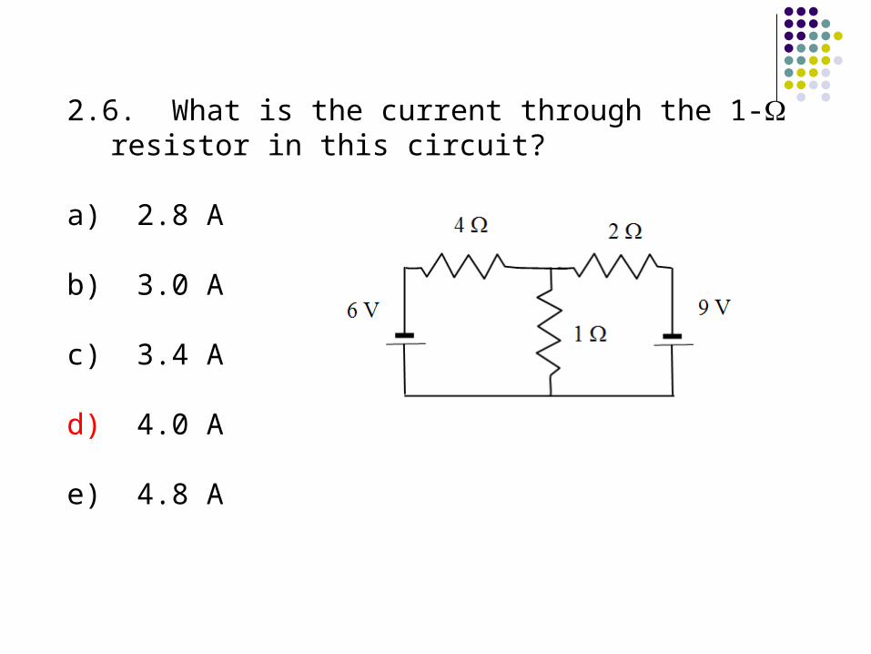
2.6. What is the current through the 1- resistor in this circuit?
a) 2.8 A
b) 3.0 A
c) 3.4 A
d) 4.0 A
e) 4.8 A
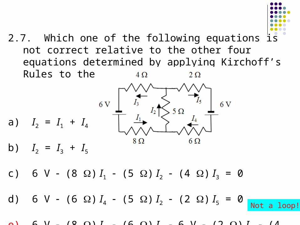
2.7. Which one of the following equations is not correct relative to the other four equations determined by applying Kirchoff’s Rules to the circuit shown?
a) I2 = I1 + I4
b) I2 = I3 + I5
c) 6 V (8 ) I1 (5 ) I2 (4 ) I3 = 0
d) 6 V (6 ) I4 (5 ) I2 (2 ) I5 = 0
e) 6 V (8 ) I1 (6 ) I4 6 V (2 ) I5 (4 ) I3 = 0Not a loop!
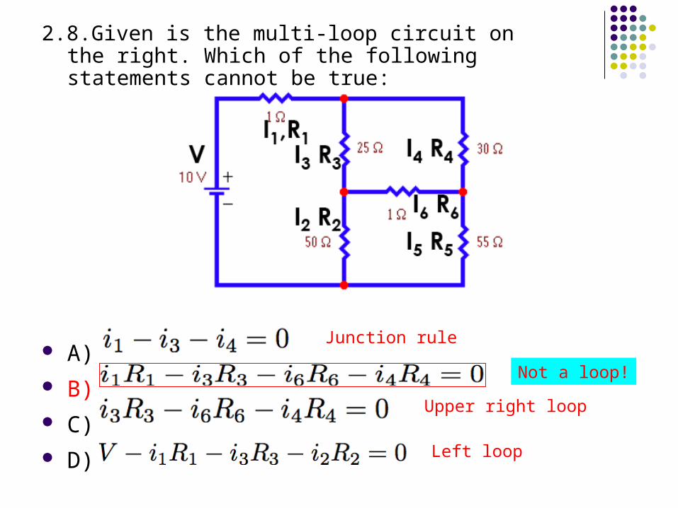
2.8.Given is the multi-loop circuit on the right. Which of the following statements cannot be true:
A) B) C) D)
Junction rule
Not a loop!
Upper right loop
Left loop
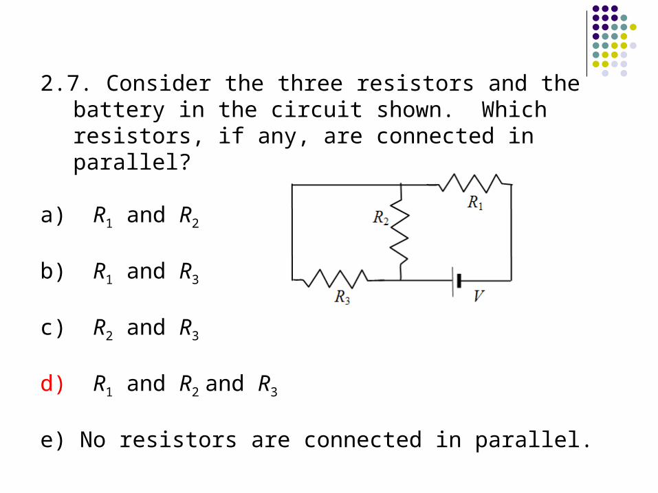
2.7. Consider the three resistors and the battery in the circuit shown. Which resistors, if any, are connected in parallel?
a) R1 and R2
b) R1 and R3
c) R2 and R3
d) R1 and R2 and R3
e) No resistors are connected in parallel.