1. GENERAL PURPOSE
91
Lawrence Berkeley National Laboratory Construction Details & Design Guidelines Facilities Division PART I ADMINISTRATIVE 1. GENERAL PAGE 1 03/24/2015 1. GENERAL PURPOSE The LBNL Construction Details & Design Guidelines (CDDG) outlines all requirements for compliance with codes, rules, regulations and LBNL standards for construction projects at Lawrence Berkeley National Laboratory. The CDDG, Part I, “Administrative Requirements,” provides an overview of the project requirements for the Architect/Engineer. These requirements include but are not limited to codes, surveys, reviews and approvals, meetings, environmental documentation, procedures for design review, tree removal, security systems, milestone deliverables, and specifications format. When the Architect/Engineer Agreement differs from the CDDG, the agreement takes precedence over information in the CDDG. GENERAL TERMS Lawrence Berkeley National Laboratory (LBNL, Laboratory) is an independent and separate entity of the University of California (UC, University) system with its own campus, administration, and funding. The Laboratory is operated by the University under contract to the Department of Energy (DOE). As the Prime Contractor for operation of the Laboratory, the University subcontracts with external entities for the performance of various services. Pursuant to the terms of the Architect/Engineer Agreement, the Subcontractor’s client is The Regents of the University of California, hereinafter called “University.” The University designates a representative, hereinafter called “University’s Representative,” the Architect/Engineer’s primary contact at the University. For construction projects at LBNL, the University’s Representative is the Facilities Design & Construction Management Department (DCM) Project Manager assigned to the project. “Architect/Engineer or Design Team” means the Architectural/Engineering or Lead Engineering design entity subcontracted to the University by an Architect/Engineer Agreement to conduct professional and design services for the duration of a specific project. In the CDDG, all references to “Architect/Engineer” means the Design Professionals on projects where design services are subcontracted through an Architect/Engineer Agreement. The Architect/Engineer or Lead Engineering design entity shall submit to the LBNL Engineering Manager, acting as Owner, for approval of the “Registered Design Professional in Responsible Charge” (RDPIRC) per California Building Code. The RDPIRC shall be designated in the building permit application as Registered Design Professional (RDP) for the project. The RDP shall be responsible for reviewing and coordinating submittal documents prepared by others, including phased and deferred submittal items, for compatibility with the design of the building.
Transcript of 1. GENERAL PURPOSE
Lawrence Berkeley National Laboratory Construction Details & Design Guidelines Facilities Division
PART I ADMINISTRATIVE 1. GENERAL PAGE 1 03/24/2015
1. GENERAL
PURPOSE
The LBNL Construction Details & Design Guidelines (CDDG) outlines all requirements for compliance with codes, rules, regulations and LBNL standards for construction projects at Lawrence Berkeley National Laboratory.
The CDDG, Part I, “Administrative Requirements,” provides an overview of the project requirements for the Architect/Engineer. These requirements include but are not limited to codes, surveys, reviews and approvals, meetings, environmental documentation, procedures for design review, tree removal, security systems, milestone deliverables, and specifications format. When the Architect/Engineer Agreement differs from the CDDG, the agreement takes precedence over information in the CDDG.
GENERAL TERMS
Lawrence Berkeley National Laboratory (LBNL, Laboratory) is an independent and separate entity of the University of California (UC, University) system with its own campus, administration, and funding. The Laboratory is operated by the University under contract to the Department of Energy (DOE). As the Prime Contractor for operation of the Laboratory, the University subcontracts with external entities for the performance of various services.
Pursuant to the terms of the Architect/Engineer Agreement, the Subcontractor’s client is The Regents of the University of California, hereinafter called “University.”
The University designates a representative, hereinafter called “University’s Representative,” the Architect/Engineer’s primary contact at the University. For construction projects at LBNL, the University’s Representative is the Facilities Design & Construction Management Department (DCM) Project Manager assigned to the project.
“Architect/Engineer or Design Team” means the Architectural/Engineering or Lead Engineering design entity subcontracted to the University by an Architect/Engineer Agreement to conduct professional and design services for the duration of a specific project. In the CDDG, all references to “Architect/Engineer” means the Design Professionals on projects where design services are subcontracted through an Architect/Engineer Agreement. The Architect/Engineer or Lead Engineering design entity shall submit to the LBNL Engineering Manager, acting as Owner, for approval of the “Registered Design Professional in Responsible Charge” (RDPIRC) per California Building Code. The RDPIRC shall be designated in the building permit application as Registered Design Professional (RDP) for the project. The RDP shall be responsible for reviewing and coordinating submittal documents prepared by others, including phased and deferred submittal items, for compatibility with the design of the building.

Lawrence Berkeley National Laboratory Construction Details & Design Guidelines Facilities Division
PART I ADMINISTRATIVE 1. GENERAL PAGE 2 03/24/2015
“Facilities Engineer” means the designated LBNL Facilities Division Engineer responsible for the portion of project scope specific to their professional knowledge and registration. In the CDDG, all references to “Facilities Engineer” means the Facilities Design Professional assigned to the project where design review services are performed by University employed Architect/Engineers.
The term “Estimated Project Construction Cost” shall mean the Architect/Engineer’s 3rd party estimate for the entire Project’s current cost of construction. It shall include the major categories of Work and such significant cost subdivisions as may be indicated by the Specifications divisions and by the type, size, and complexity of the Project.
Throughout the Project, the RDP is expected to keep the Project Cost within the Construction Budget and is responsible to periodically submit current construction cost estimates to verify that the Project is within the Construction budget.
CODES
The University is not subject to the building ordinances and zoning requirements of local political jurisdictions (City of Berkeley, City of Oakland, and County of Alameda); building permits are issued by the Facilities Engineering Department for LBNL on-site projects. Off-site projects are required to comply with all applicable local codes and ordinances.
Building codes, standards, federal and state legislation, and federal, state, and local agency regulations affect University projects. The University is its own enforcement agency for all code requirements. The official organization performing construction project reviews and approvals is the LBNL Facilities Engineering Department.
The design shall be in compliance with the following Codes, Regulations, Standards, Acts, and Manuals. In case of any conflict in the code requirements, the most stringent one shall apply. The California Building Standards Code adopted by the Building Standards Commission (BSC), Division of the State Architect/Access Compliance (DSA/AC), and the State Fire Marshal (LBNL Fire Marshal) are applicable to LBNL facilities. The following list identifies the codes and regulations in effect for all projects at LBNL. The University shall provide copies of DOE and LBNL specific publications upon request.
1. California Code of Regulations (CCR), latest edition comprising:
a. Title 8, Industrial Relations b. Title 17, Public Health c. Title 19, Public Safety d. Title 20, Public Utilities and Energy e. Title 21, Public Works f. Title 24, California Building Standards Code

Lawrence Berkeley National Laboratory Construction Details & Design Guidelines Facilities Division
PART I ADMINISTRATIVE 1. GENERAL PAGE 3 03/24/2015
Part 1, Administrative Code Part 2, California Building Code (CBC) Part 3, California Electrical Code (CEC) only listed exceptions from latest edition of NEC (NFPA 70) as included in CEC edition specified herein. Part 4, California Mechanical Code (CMC) Part 5, California Plumbing Code (CPC) Part 6, California Energy Code (CEC) Part 8, California Historical Building Code Part 9, California Fire Code (CFC) Part 10, California Existing Building Code Part 11, California Green Building Standards Code Part 12, California Reference Standards Code
g. Title 26, Toxics
2. NFPA National Fire Codes, latest edition.
3. NFPA 70: National Electrical Code (NEC), latest edition.
4. National Electrical Safety Code, ANSI C2, latest edition.
5. NFPA 70E: Standard for Electrical Safety in the Workplace, latest edition.
6. Illuminating Engineering Society of North America (IES), latest edition.
7. Occupational Safety and Health Act (OSHA).
8. General Services Administration 41 CFR Part 101-19, Construction and Alteration of Public Buildings.
9. Americans with Disabilities Act (ADA).
10. Energy Conservation Performance Standards, 10 Code of Federal Regulations (CFR), Part 434, Energy Code for New Federal Commercial and Multi-Family High Rise Residential Buildings (Mandatory for Federal Buildings).
11. American National Standards Institute (ANSI) Standards.
12. The American Society of Heating and Air Conditioning Engineers (ASHRAE) Handbooks and Standards, latest edition.
13. Sheet Metal and Air Conditioning Contractors' National Association (SMACNA) Standards, latest edition. Exception: For seismic bracing refer to "Lateral Force Design Criteria," RD3.22 of the LBNL Construction Details & Design Guidelines, Volume 4 - RDs.

Lawrence Berkeley National Laboratory Construction Details & Design Guidelines Facilities Division
PART I ADMINISTRATIVE 1. GENERAL PAGE 4 03/24/2015
14. The American Society of Mechanical Engineers (ASME) Standards and Codes, latest edition.
15. The American Society for Testing and Materials (ASTM) Standards, latest edition.
16. Air Moving & Conditioning Association (AMCA) Fan Test Code, latest edition.
17. Associated Air Balance Council (AABC) National Standards for Total System Balance.
18. Factory Mutual Engineering Corp. (FM) Approval Guide and Loss Prevention Data Sheets, latest edition.
19. Underwriters' Laboratories, Inc. (UL) Standards and "Building Materials, Fire Protection Equipment, and Fire Resistive Directories."
20. LBNL Long-Range Development Plan (LRDP), current version as approved by the University and the DOE.
21. Lawrence Berkeley Laboratory Health and Safety Manual, Publication 3000, latest edition.
22. "Lateral Force Design Criteria," RD3.22 of the CDDG, Volume 4 - RDs.
23. "Checking of Architecture and Engineering Documents," RD3.8 of the CDDG, Volume 4 - RDs.
24. Life Cycle Costing Manual for the Federal Energy Management Program, National Institute of Standards and Technology, Handbook 135.
25. LBNL Energy Conservation Report Specifications.
26. Manual of Professional Practice, Quality in the Construction Project, a manual published by the American Society of Civil Engineers. Refer to "Checking of Architecture and Engineering Documents," RD3.8 of the CDDG, Volume 4 - RDs.
27. The Project Design follows the Design Program developed, as noted in the LBNL Project Design Requirements (PDR).
EFFECTIVE CODE DATE
The effective code date for new and remodeled University building projects is the edition of the CCR, Title 24, in effect at the time of the approved final submittal of Preliminary Drawings (Design Development Drawings and Specifications). The

Lawrence Berkeley National Laboratory Construction Details & Design Guidelines Facilities Division
PART I ADMINISTRATIVE 1. GENERAL PAGE 5 03/24/2015
date of the approval of this submittal is the official “date of record” for the Project. The edition of CCR, Title 24, in effect on that date shall be applied for the duration of the Project. Final Preliminary Drawings shall be submitted for approval regardless if the Design-Bid-Build or Design-Build requisition process is used.
DESIGN CHANGE AUTHORIZATION
The Architect/Engineer Agreement enumerates all categories of additional services that shall be compensated by the University when authorized in writing by the University’s Representative prior to the RDP’s execution of the Work. Additional services shall be authorized by means of a Design Change Authorization form. If approved by the University’s Representative, this form shall also be used to amend the Architect/Engineer Agreement if the time of service, the Project scope, or the Project budget is changed.
CIVIL SURVEYS, GEOTECHNICAL REPORTS, AND OTHER REPORTS
The University shall provide copies of surveys and test reports to the RDP for review and evaluation. Unless noted otherwise, the University shall supply all survey information.
COORDINATION AND COMMUNICATION
1. Coordination
a. The RDP shall coordinate issues concerning scope, budget, and schedule with the University’s Representative.
b. The RDP design team members may communicate directly with corresponding LBNL design team members concerning clarification of LBNL standard design practices, location of record documents, systems selection, coordination of information on drawings and specifications, and other design and technical issues. All discussions and decisions shall be documented by the Architect/Engineer and copied to the University’s Representative.
2. Meetings
a. The RDP shall be responsible for participating in regular meetings at the Facility through each phase of the Project for the purpose of explaining the Project’s design and reviewing the Project’s progress.
The RDP and the LBNL Project Manager shall agree on the frequencies of the meetings based on the “Graded Approach” as delineated in the “LBNL Commissioning Process: Standard Operating Procedure.”

Lawrence Berkeley National Laboratory Construction Details & Design Guidelines Facilities Division
PART I ADMINISTRATIVE 1. GENERAL PAGE 6 03/24/2015
b. At the beginning of the schematic design phase, the RDP and consultants shall:
1. Visit the Project site to become familiar with existing site conditions, including the site location and size, utility capacities, and connection options of external utilities.
2. For alteration projects, visit all relevant areas of the existing buildings to be altered.
3. The RDP shall participate in the Project commissioning process per “LBNL Commissioning Process: Standard Operating Procedure” including the completion of the Basis of Design (BOD) document.
c. After schematic design, the RDP shall submit a schedule of project coordination meetings with the provision that scheduled meetings shall be held on an agreed scheduled basis.
d. All meetings shall be documented by the RDP and minutes distributed to the University’s Representative and the RDP’s team members within 48 hours of a meeting.
e. Meeting minutes shall clearly describe every key item discussed and identify action items with responsible parties. A record of outstanding action items shall be maintained in the meeting minutes and updated with each meeting.
f. The RDP shall maintain a log of completed action items as a record of decisions made.
g. Meetings shall be scheduled at agreed-upon locations as required in the Project Design Requirements (PDR). If not noted, meetings shall be as follows:
Once a week Preliminary Design phase Every three weeks Final Design phase Every two weeks Construction phase
h. The schedule shall specifically identify the following meetings, if required by the PDR:
Kick-Off Meeting (0% Preliminary Design) including Commissioning Process
Program/Conceptual Design/Budget Reconciliation Meeting (10% Preliminary Design)
Preliminary Design Review Meeting (100% Preliminary Design) Regents' Review Meeting, if needed Design Development Review Meeting (50% Final Design) Final Design Reconciliation Meeting (100% Final Design) Pre-Bid Site Meeting Construction Kick-Off Meeting

Lawrence Berkeley National Laboratory Construction Details & Design Guidelines Facilities Division
PART I ADMINISTRATIVE 1. GENERAL PAGE 7 03/24/2015
Punch List Reconciliation Meeting
3. Telephone Communication
a. The RDP shall document in writing, with a copy to the University’s Representative, all telephone conversations that result in interpretation, changes, additions, or deletions to the program and/or design criteria requirements.
4. Transmittals
a. All correspondence and submittals shall be routed through the University's Representative and the RDP, and shall be accompanied by a written and dated transmittal that describes the information submitted and action required. Each transmittal shall include LBNL subcontract and job numbers.
COMMISSIONING
The RDP shall participate in Project Commissioning throughout the Project starting from the Conceptual Design until the Project is fully commissioned and extended to a minimum of 11 months after substantial completion as part of the RDP’s Design Warranty Services stated in Section 6, Bidding & Construction.
As part of the Project and Commissioning Process, the RDP shall prepare the Basis of Design (BOD) for the project.
1. Requirements
The Basis of Design (BOD) document records the major thought processes and assumptions behind design decisions made to meet the Owner’s Project Requirements (OPR). The Owner’s Project Requirements are intended to capture “what” the owner needs and expects from a project. The Construction Documents detail “how” the Owner’s Project Requirements shall be physically achieved. The BOD captures important information linking the “what” and “how”, by the design team.
2. Objective
a. Provide the parties involved with a Project, at each phase in the process, an understanding of the underlying thinking that led to the selection of specific components, assemblies, systems, and system integrations.
b. Provide a design narrative that provides an overview of assemblies and systems.

Lawrence Berkeley National Laboratory Construction Details & Design Guidelines Facilities Division
PART I ADMINISTRATIVE 1. GENERAL PAGE 8 03/24/2015
c. Document changes to the Basis of Design that often occur as a design evolves.
3. Procedure
a. Schematic Design Phase: During the Schematic Design Phase, the BOD consists of the written description and discussion of the concepts and features the designer intends to incorporate into the design.
b. Design Development Phase: In subsequent design phases the design narrative is a description of what they have incorporated to meet the Owner’s Project Requirements and associated performance criteria.
c. The BOD shall be updated with each subsequent design submission, with increasing specificity as applicable by the design team.
4. Content
The content of the Basis of Design document shall vary from project to project and system to system. The development of the BOD shall be based on the Graded Approach as determined by the LBNL Commissioning Director and described in the Commissioning Process: Standard Operating Procedure, but in general it should address the following minimum topics. Refer to Commissioning Process: Standard Operating Procedure for the definition of LBNL Commissioning Director and Commissioning Authority.
a. Specific codes, standards, and guidelines considered during design of the facility and designer interpretations of such requirements.
b. Information regarding ambient conditions (climatic, geologic, structural, existing construction) used during design.
c. Assumptions regarding usage of the facility. d. Expectations regarding system operation and maintenance. e. Performance criteria that the system was designed to meet – linked
to the Owner’s Project Requirements. f. Specific design methods, techniques, and software used in design. g. A narrative statement of design that verbally describes how the
designer intends to meet the Owner’s Project Requirements. h. A narrative statement of operation that verbally details how the
facility is expected to operate under various situations (e.g., normal operation, extreme event, emergency, or maintenance during operation).

Lawrence Berkeley National Laboratory Construction Details & Design Guidelines Facilities Division
PART I ADMINISTRATIVE 1. GENERAL PAGE 9 03/24/2015
i. A listing of specific manufacturer makes and models used as the basis for drawings and specifications.
5. Verification with Owner’s Project Requirements (OPR)
During the project review process as outlined in the following sections of the CDDG, the LBNL Commissioning Team and the Facilities Engineering Department shall verify the BOD with the OPR. In order for the Commissioning Team to easily compare the OPR and the BOD, the Design Team shall, to the extent possible, adhere to the following high level organization of contents. The BOD shall be reviewed in accordance with the Owner’s Project Requirements. a. Overview and Scope b. General Requirements c. Space Plan d. Design Process e. Structural System f. Heating, Ventilation, and Air Conditioning f. Electrical Systems g. Commissioning h. Sustainability i. Maintainability j. Building Envelope k. Plumbing Systems l. Fire Alarm System m. Life Safety Systems n. Data and Communication Systems o. Security and Access p. Laboratory Process q. Other systems not included previously
VALUE ENGINEERING PROGRAM
On major projects, the University may require Value Engineering (VE) sessions to evaluate program requirements and determine the cost effectiveness of various elements of the project or buildings. Verify with the University’s Representative and the terms of the Architect/Engineer Agreement to determine if the VE program applies.
Participants of the program are the RDP, the RDP’s Consultants, Professional Peers experienced with building type, Special Consultants (e.g., Geotechnical Engineer), the Facilities Engineering Department, User Representatives, and others deemed appropriate by the University. The RDP shall prepare the following for the VE session:
1. Copies of the current status documents.
Lawrence Berkeley National Laboratory Construction Details & Design Guidelines Facilities Division
PART I ADMINISTRATIVE 1. GENERAL PAGE 10 03/24/2015
2. Copies of a life cycle analysis of all proposed building systems, major components, and alternatives addressing the following:
a. Projected initial cost of the system.
b. Projected yearly operational cost.
c. Projected estimated replacement cost and estimated life expectancy.
3. Copies of the current Estimated Project Construction Cost.
Value Engineering sessions may be scheduled as follows. Actual dates shall be established by agreement between the RDP and the University’s Representative.
1. Late Schematic Design Phase:
a. Evaluation of Alternatives
b. Selection of Alternatives
2. Middle to Late Design Development Phase:
a. Design Review
b. Alternative Technical Solutions
c. Cost Evaluations
d. Priorities and Trade-Offs (as necessary)
WITNESS and HOLD INSPECTION PLAN
The Registered Design Professional shall develop the Witness and Hold Inspection Plan for architectural and each individual engineering descipline. The Witness and Hold Inspection Plan shall form part of the drawing set and shall be titled accordingly.
The architectural Inspection Plan shall include all prescriptive ADA requirements. The Engineer of Record (EOR) of each discipline shall delineate the degree of test, inspection and Statement of Special Inspection when required per Code or specifications for the work being done. The Inspection Plan shall allow room for the IOR and/or the ADA Compliance Officer for final sign off.

Lawrence Berkeley National Laboratory Construction Details & Design Guidelines Facilities Division
PART I ADMINISTRATIVE 2. REVIEWS & APPROVALS PAGE 11 03/24/2015
2. REVIEWS & APPROVALS
INTRODUCTION
University projects require review prior to their entering the formal approval process. Project items to be reviewed include design and cost, site, seismic safety, and environmental impact. For Capital Projects, program and funding approvals occur prior to site, design, and environmental approvals. For Small Projects, program and funding approval occurs prior to the start of projects.
The review and approval processes described below apply to typical projects. Projects with multiple approvals require additional lead-time because of their complexity and to resolve any difficulties. In addition to these University approvals, various state, local, and funding entities may require their own reviews and approvals for certain projects.
The RDP shall cooperate with the reviewers and cost estimator and participate in the reviews.
DESIGN REVIEWS
The RDP shall submit documents for the University's review in accordance with the following schedule:
Review Dwgs Specs Calcs Cost Est Preliminary Design
X List X
100% X X X X
Final Design 50%
X X X X
95% X X X X
Final 100% X X X X
The documents for each discipline shall be at the same stage of completion and in sufficient detail to permit a complete review by the University. Piecemeal submittals shall not be acceptable. The drawings shall be arranged by design discipline, and have consistent sequential numbering. The RDP shall projectize the LBNL Master Specifications using tracked changes in the 100% Preliminary Design submittals for LBNL review. The LBNL Project Team shall review the submittals for compliance with program requirements and the authorized scope, schedule, and budget.
The University’s Representative shall return written comments and marked-up drawings to the RDP. Each new submittal shall incorporate the comments and

Lawrence Berkeley National Laboratory Construction Details & Design Guidelines Facilities Division
PART I ADMINISTRATIVE 2. REVIEWS & APPROVALS PAGE 12 03/24/2015
markups from previous reviews unless otherwise agreed to in writing between the RDP and the Facillities Engineering Department.
Submitted plans and specifications, which are obviously incomplete or incorrect, shall be returned to the RDP with a request for compliance with these requirements before the review is resumed by the University.
NUMBER OF SUBMITTAL COPIES
The RDP shall submit one (1) bound full size set and one (1) loose half size set of drawing prints, and one (1) bound copy and one (1) loose copy of specifications, calculations, and cost estimates for all required submittals. Drawings shall be on LBNL standard title blocked "D" size (22x34 inches) sheets with notations, dimensions, and lettering sizes to permit legible half-size reduction. In addition, drawings shall also be submitted in electronic Portable Document Format (PDF) form.
For submission requirements for electronic CAD files, refer to “CAD Standards,” RD3.10 of the CDDG, Volume 4 - RDs.
Submitted drawings that are not in compliance with RD3.10, illegible, obviously incomplete or incorrect, shall be returned to the RDP with a request for compliance with these requirements before the review is resumed by the University.
APPROVALS
All approvals shall be in the form of written and dated communications by the University’s Representative. Upon receipt of written authorization, the RDP shall proceed with the next phase of the project.
Reviews and Approvals are part of the Quality Assurance Program. The Reviews include both internal reviews by Facilities Engineers and Project Management and external reviews by agencies or firms outside the Laboratory.
Internal: Internal LBNL Design Reviews are performed by:
1. Facilities Engineering Department. 2. Subject Matter Experts (SMEs). 3. Project Manager. 4. Client/User. 5. LBNL Fire Marshal. 6. Environment, Health and Safety Team Members. 7. Mechanical Safety Subcommittee. 8. Maintenance & Operations Team Members. 9. Quality Assurance.
10. Procurement. 11. LBNL Commissioning Team. 12. Space Planning. 13. Sustainability.

Lawrence Berkeley National Laboratory Construction Details & Design Guidelines Facilities Division
PART I ADMINISTRATIVE 2. REVIEWS & APPROVALS PAGE 13 03/24/2015
External: External Design Reviews may be required by:
1. CEQA. 2. NEPA. 3. DOE/External Independent Review (EIR) contracted by DOE. 4. Office of the President. 5. The Regents of the University of California. 6. Third Party for Hazardous Materials. 7. Third Party for Structural. 8. Value Engineering. 9. Third Party for Cost Estimates. 10. LBNL subcontracted Commissioning Authority.
REVIEW OF PRELIMINARY DESIGN, FINAL DESIGN, AND FINAL CONSTRUCTION DOCUMENTS
Prior to the beginning of the Schematic Design phase, the University’s Representative shall provide the RDP with the Project Design Requirements (PDR) describing the project-specific program design requirements and specific tasks to be performed by the RDP. During the Schematic Design and Design Development phases, the PDR shall be translated into a viable design which is both economically and architecturally appropriate to all site, design, and cost requirements.
Periodic reviews, including meetings to discuss University policy and legal requirements, shall be required. At the various stages of Project development, reviews by the University of Drawings, Specifications, and related documents prepared by the RDP shall be conducted. The RDP and their consultants shall coordinate and check for completeness of all documents prepared for review prior to submitting them to the University’s Representative.
The University’s review of Drawings and related documents at the various stages of Project development is intended to determine that:
1. The RDP has completed the work of that phase.
2. The RDP’s design satisfies the University programmatic needs.
3. The Project design is within the stipulated scope and Project budget.
4. The Project is in conformance with University administrative policies and procedures including the CDDG.
The University’s review and approval of the RDP’s Drawings, designs, and related documents shall not relieve the RDP from responsibility for errors and omissions in the RDP’s work.
PLAN CHECK

Lawrence Berkeley National Laboratory Construction Details & Design Guidelines Facilities Division
PART I ADMINISTRATIVE 2. REVIEWS & APPROVALS PAGE 14 03/24/2015
To meet fire code requirements, review and approval by the LBNL Fire Marshal are required at Final Construction Document completion. The University’s Representative shall coordinate all reviews with the Facilities Engineering Department for building code and standards compliance and with the LBNL Fire Marshal’s Office for fire safety and fire code compliance. Corrections required by the Facilities Engineering Department and the LBNL Fire Marshal shall be incorporated into the contract documents by the RDP before advertisement for bid. LBNL Fire Marshal and Facilities Engineering Department reviews occur during Preliminary Design and Final Design. Certification is to occur after 100% Final Construction Documents are completed.
Approval of the Preliminary Design, Final Design, and final Construction Documents by DOE is required and is performed by the University’s Representative. The RDP shall support the University’s Representative in obtaining DOE approvals.
ARCHITECTURAL DESIGN REVIEW
The University has been delegated the authority to approve the project for compliance with the planning and design conditions established in the approved LBNL Long-Range Development Plan (LRDP). The University must approve sites that are not in accordance with the LRDP. The University requires a formal Architectural Design Review to assess and comment on design submittals for compliance with the Planning Design Guidelines.
ENVIRONMENTAL REVIEW AND DOCUMENTATION (CEQA & NEPA)
California Environmental Quality Act (CEQA) and National Environmental Policy Act (NEPA) review begins during project planning phases, when projects are classified by their probable impact and need for environmental documentation. The Facilities Division Environmental Planning Group conducts CEQA review and provides NEPA review assistance to the Department of Energy; Facilities Division also prepares any necessary environmental documentation. A project with little or no potential for environmental impacts may be generally or categorically exempt from further CEQA review and/or categorically excluded from further NEPA review. In other instances, a project may be considered to be covered under existing CEQA and/or NEPA documentation and decisions, in which case no further CEQA or NEPA review may be necessary. Such determinations are made by the Facilities Division Environmental Planning Group.
If further review is required, it would typically be in the form of an Initial Study (CEQA) and/or an Environmental Assessment (NEPA). Initial Studies identify and analyze areas of environmental concern. If any impacts are found to be potentially significant—and particularly if they are considered significant and unavoidable—preparation of an Environmental Impact Report (EIR) is usually required. If no significant, unmitigatable impacts are identified, a Negative

Lawrence Berkeley National Laboratory Construction Details & Design Guidelines Facilities Division
PART I ADMINISTRATIVE 2. REVIEWS & APPROVALS PAGE 15 03/24/2015
Declaration is typically prepared instead. Initial Study / Negative Declarations and EIRs are usually “tiered” from LBNL’s programmatic CEQA document—the 2006 Long Range Development Plan EIR. Under NEPA, Environmental Assessments perform the same function as Initial Studies. If significant and unavoidable impacts are identified, preparation of Environmental Impact Statement (EIS) is usually required; otherwise, the federal Lead Agency typically may issue a Finding of No Significant Impact (FONSI). With both Initial Studies and Environmental Assessments, a 30-day public review and comment period is provided before the documents are finalized.
Environmental Impact Reports (EIRs) and Environmental Impact Statements (EISs) are extensive documents that require the assistance of expert consultants. They both include formal, public scoping processes; the solicitation of Draft EIR / EIS review and comment by the public and agencies; public hearings; and careful review and response to comments in the Final EIR and EIS documents. The finalized versions of these documents undergo a formal decision process by their respective Lead Agencies: The University must provide EIR “certification” before the University may approve the subject project; the Department of Energy must issue a “Record of Decision” approval document for the EIS before it may approve the subject proposed action.
TREE REMOVAL PROTOCOL
Tree removal is coordinated by the University’s Representative with the Facilities Environmental Planning Group. No tree is to be considered for removal until the University’s Representative has confirmed in writing that the Facilities Environmental Planning Group and Facilities Maintenance & Operations accept and approve the removal.
INDEPENDENT DESIGN AND COST REVIEW
DOE and University policies require independent Architectural Design Review and Independent Cost Estimates of projects that are Line Item, General Plant Projects (GPP), and Institutional GPP (IGPP) Projects.
Independent reviewers must be appropriately licensed, must have no previous connection with the project being reviewed, and must not be LBNL employees.
The independent design review shall be performed early in the preparation of design, at appropriate intervals during design, and at the time of completion of design. The review shall focus on, but need not be limited to, the compatibility of the design with its setting and the appropriateness of the design to its functional program and the project budget. The DOE External Independent Review (EIR) is independently subcontracted by DOE. The RDP shall support the University’s Representative in the DOE EIR.
INDEPENDENT COST ESTIMATE

Lawrence Berkeley National Laboratory Construction Details & Design Guidelines Facilities Division
PART I ADMINISTRATIVE 2. REVIEWS & APPROVALS PAGE 16 03/24/2015
To ensure that cost considerations are fully incorporated into design decisions, the University requires that an Independent Cost Estimate be conducted on all Line Item, GPP, and IGPP Projects. Independent Cost Estimates shall be completed prior to the DOE EIR and form part of the package for the DOE EIR.
For Small Projects, a third party cost estimate shall be prepared prior to the start of construction of the project. INDEPENDENT SEISMIC REVIEW
To ensure that seismic safety and other structural considerations are fully incorporated into Capital Project design, purchase, and lease decisions, an independent review shall be conducted of the structural seismic design of all Capital Projects, whether new construction or remodeling, which involve structural design and are intended for human occupancy or which affect human safety, and include review of non-structural building elements.
It is University policy, to the maximum extent feasible by present earthquake engineering practice, to acquire, build, maintain, and rehabilitate buildings and other facilities which provide an acceptable level of earthquake safety for guests, employees, and visitors who occupy those buildings and other facilities at all locations where University operations and activities occur. Feasibility is to be determined by weighing the practicability and cost of protective measures against the gravity and probability of injury resulting from a seismic occurrence. University policy on independent seismic review states in part:
1. Independent review shall be conducted of the structural seismic design of all capital improvement projects, whether new construction or remodeling, which involve structural design and are intended for human occupancy, or which affect human safety. The review shall be initiated early in the project’s life, and preferably during the preparation of schematic designs, so that it can be performed in conjunction with the independent design and cost reviews and value engineering processes, where applicable, and shall be continued at appropriate times during the design process. In all cases, working drawings and calculations shall be reviewed for conformance of the new work to the most current applicable seismic design code requirements.
2. Independent review shall be conducted of the structural seismic design of facilities being considered for lease or purchase for University purposes. The depth and detail of review shall be appropriate to the type of structure, its intended use, its age, length of time to be leased, percentage of structure to be leased, and the geological conditions of its location.
3. Prior to the substantial completion of the Project, the University’s Representative shall obtain a confirmation letter from the Independent
Lawrence Berkeley National Laboratory Construction Details & Design Guidelines Facilities Division
PART I ADMINISTRATIVE 2. REVIEWS & APPROVALS PAGE 17 03/24/2015
Seismic Reviewer that the building can be occupied.
REGENTS’ ITEMS
After the independent reviews are completed, the final steps in The Regents approval process are The Regents design review and the preparation of The Regents’ Action Item (Regents’ item) for submission. Procedures and guidelines for preparing and submitting Regents’ items, the design review, and Regents’ presentation process are outlined in the UCOP Facilities Manual, Volume 3, Chapter 5. The Office of the President (UCOP) is included in the Facility design review to provide an opportunity for University input on design content and review of Regents policy.
The following materials may be used for the meeting and the RDP may be contracted to provide:
1. A site map or aerial photograph of the project area.
2. Photographs of surrounding areas.
3. Land-use plan of the Long-Range Development Plan (provided by the Facilities Environmental Planning Group.)
4. Site plan.
5. Floor plans.
6. Elevations of all sides.
7. Major sections.
8. Artist renderings and perspective views.
9. Design analysis, life-cycle cost analysis, and other support data.
REGENTS’ DESIGN APPROVAL
Building design must be approved by The Regents in the following cases:
1. Building projects with a total project cost in excess of $5 million, except when such projects consist of the following:
a. Alterations or remodeling where the exterior of the building or site infrastructure is not materially changed.
2. Capital improvement projects of any construction cost when, in the judgment of the Lab Directorate, a project merits review and approval by The Regents because of budget matters, fund-raising activities,

Lawrence Berkeley National Laboratory Construction Details & Design Guidelines Facilities Division
PART I ADMINISTRATIVE 2. REVIEWS & APPROVALS PAGE 18 03/24/2015
environmental impacts, community concerns, or other reasons.
Requirements for approval are summarized in the UCOP Facilities Manual. Because specific procedures and schedules for design review and approval may change, the University’s Representative should confirm current practices with the UC Office of the President.
Lawrence Berkeley National Laboratory Construction Details & Design Guidelines Facilities Division
PART I ADMINISTRATIVE 3. PRELIMINARY DESIGN PHASE PAGE 19 03/24/2015
3. PRELIMINARY DESIGN PHASE
PRELIMINARY DESIGN PHASE REQUIREMENTS
The following are considered to be minimum submission requirements for the preliminary design drawings for all projects involving construction of a new building or alteration of or additions to an existing building. Prior to the preliminary design documents submittal, the RDP shall evaluate the Project’s programmatic requirements, promptly call attention to any discrepancy contained therein, and request direction from the University’s Representative regarding these discrepancies. The RDP shall prepare a written evaluation of any imbalance between the Construction Budget and the Project program requirements. The RDP shall be prepared to present program or design adjustment alternatives for University consideration when adjustments are needed to bring the Project scope, schedule, and budget into alignment.
CIVIL REQUIREMENTS
1. Site Plans (scale: 1" = 20' or larger)
a. Horizontal control with 200-foot University grid coordinates.
b. Location and extent of existing and proposed structures on site within at least a 300-foot radius measured from the exterior walls of the proposed building. Identify structures, building numbers/descriptions and streets by proper names. Indicate references to a benchmark and baseline.
c. Existing and proposed contours.
d. Method of general drainage of the site to be affected by the proposed building.
e. Indication of all exterior elements (e.g., outdoor facilities, streets, service drives, parking areas, handicapped access, paved areas, covered walks, landscape development, stairs, retaining walls, fire hydrants, etc.).
f. Site utility plans, including off-site utilities related to the project. Separate mechanical and electrical site utility plans may be required.
g. All drawings shall include a graphic scale and a north arrow.
2. Quality Control and Quality Assurance
The RDP shall include a listing of all Civil installation requirements that must be tested and inspected by University Inspectionors as part of the

Lawrence Berkeley National Laboratory Construction Details & Design Guidelines Facilities Division
PART I ADMINISTRATIVE 3. PRELIMINARY DESIGN PHASE PAGE 20 03/24/2015
general requirements of the work. The listing shall form part of the constract documents. All code and LBNL specific required testing and inspection shall be included in the listing.
STRUCTURAL REQUIREMENTS
1. Foundation and Earth Retaining Structure Drawings (scale same as Architectural drawings but no less than 1/8” = 1’-0”)
a. Indicate complete foundation or earth retaining system in plan, and, for earth retaining structures, elevation. The drawings shall show soil borings locations and dimensions/sizes required for an accurate cost estimate.
b. Piles, caissons, and tie backs shall be numbered in the appropriate view and a tabular log shown on the drawings. The log shall at a minimum indicate the design and “as built” length, load tests results, etc.
c. All drawings shall include a graphic scale and a north arrow.
2. Framing Plans and Elevations (scale same as Architectural drawings but not less than 1/8” = 1’-0”)
a. Indicate vertical and lateral load carrying system of the structure complete with member sizes and dimensions required for an accurate cost estimate.
b. Show the structural support sizes and appurtenances for specialty systems such as seismic/vibration isolation systems, cranes, hoists, etc. Show the structural support sizes for major equipment.
c. Indicate design live load for floors, platforms, and roofs on the drawings.
d. Indidate the seismic design criteria on the drawings.
3. Calculations shall be prefaced with a narrative description of the basis of design, special problems, or considerations with the preferred method of accomplishment. The calculations should be indexed and sufficiently complete to provide an engineering basis for selection of the structural elements shown on the drawings and an accurate basis for the cost estimate.
4. Quality Control and Quality Assurance

Lawrence Berkeley National Laboratory Construction Details & Design Guidelines Facilities Division
PART I ADMINISTRATIVE 3. PRELIMINARY DESIGN PHASE PAGE 21 03/24/2015
The RDP shall include a listing of all Structural installation requirements that must be tested and inspected by University Inspectionors as part of the general requirements of the work. The listing shall form part of the constract documents. All code and LBNL specific required testing and inspection shall be included in the listing.
ARCHITECTURAL REQUIREMENTS
1. Site Plans (scale: 1" = 20' preferred but no smaller than 1” = 40’)
a. Horizontal control with 200' University grid coordinates.
b. Overall dimensions of proposed building(s) including any alternates.
c. Various floor and grade elevations, including those of stairways, walls, terraces, etc.
d. Section(s) through site, if necessary, to explain changes in level in the proposed building as related to the site and adjacent structures.
e. Distances from adjacent buildings, streets, and structures. Indicate type of construction of adjacent buildings and explain compliance with code required clearances for types of construction proposed. Indicate fence lines and implied property lines and show critical dimensions and clearances.
f. Small scale site map identifying project location.
g. All drawings shall include a graphic scale and a north arrow.
2. Floor Plans (scale: not less than 1/8" = 1'-0")
a. Locations, sizes, and space numbers of all programmed spaces and other required gross areas, including corridors (width), stairs, toilets, janitors' closets, mechanical spaces, storage rooms, etc. Floor plans for additions or alterations to existing buildings shall show the existing floor plan, indicating the existing space usages.
b. Location of doors and windows. Indicate door swings.
c. Overall dimensions of each major area of the building(s).
d. Fire ratings of fire separations, exit enclosures, fire doors, and similar elements as required by applicable codes.
e. Location and swing of all fire and exit doors. Indicate area and occupancy fire separations.

Lawrence Berkeley National Laboratory Construction Details & Design Guidelines Facilities Division
PART I ADMINISTRATIVE 3. PRELIMINARY DESIGN PHASE PAGE 22 03/24/2015
f. Provide code analysis floor plan diagrams (1/16” = 1’-0” min. scale) with occupancy types noted, exit path indicated, required exits noted with correct separation, vertical chases and stairways shown, identify rated construction, clarify occupancy loads, and number of required exits.
3. Provisions for making facilities accessible to, and usable by, the physically handicapped as required by the PDR.
4. Location of all plumbing fixtures such as lavatories, floor drains, toilets, urinals, service sinks, drinking fountains, fire hose cabinets, fire extinguishers, and required sprinkler systems.
5. All principal built-in features such as built-in casework, fixed laboratory equipment, display cases, counters, shelves, lockers, etc.
6. Location of all movable items of furniture and equipment listed in the space description sheets. Differentiate from built-in furniture and equipment.
7. Elevations and Sections (scale: not less than 1/8" = 1'-0")
a. Include all elevations for the building. Show windows, doors, window vents, stairs, platforms, retaining walls, etc. Indicate grades, paved areas, etc.
b. Indicate floor heights and window sill and head heights.
c. Include longitudinal and transverse sections for each major area, indicating floor elevations, finish exterior grades, ceiling heights, pipe tunnels, unexcavated areas, basement and area-ways, roof lines, and parapets.
d. Reference all sections and elevations to building plans. If necessary, include small scale plan or diagram to indicate section lines for each elevation and section.
e. Include larger scale (1/4") indication of special design features with notes related to materials and design.
8. Interior Details
a. Draw detail plans, sections, and elevations at not less than 1/4" = 1'-0" scale.
b. Study the following space types thoroughly and illustrate details clearly for review by the User, Construction Projects, and the Facilities Engineering Department.

Lawrence Berkeley National Laboratory Construction Details & Design Guidelines Facilities Division
PART I ADMINISTRATIVE 3. PRELIMINARY DESIGN PHASE PAGE 23 03/24/2015
1) Offices. 2) Conference Rooms. 3) Laboratories and any other scientific program spaces. 4) Toilet and locker rooms. 5) Utility spaces or locations.
c. Include an interior finish schedule which indicates, in general terms, all floor, wall, and ceiling finishes, along with any special items of finish.
9. Presentation Material
a. Some projects may require presentation drawings, three-dimensional models, and/or photographs or slides for presentation to the Facilities Engineering Department and to The Regents for approval.
b. Verify all requirements for presentation materials with the University’s Representative.
c. On new building projects, provide:
1) A display board with mounted samples of the actual exterior materials.
2) Study models as needed to analyze various alternative siting and massing schemes.
3) A narrative description explaining the design concept and important features of the Project.
10. Quality Control and Quality Assurance
The RDP shall include a listing of all Architectural installation requirements that must be tested and inspected by University Inspectionors as part of the general requirements of the work. The listing shall form part of the constract documents. All code and LBNL specific required testing and inspection shall be included in the listing.
MECHANICAL AND ELECTRICAL REQUIREMENTS
1. The building mechanical and electrical systems can critically impact the size and shape of the building, the interior space allocation, overall project costs, building electrical load, and future energy and maintenance costs (especially in large buildings.)

Lawrence Berkeley National Laboratory Construction Details & Design Guidelines Facilities Division
PART I ADMINISTRATIVE 3. PRELIMINARY DESIGN PHASE PAGE 24 03/24/2015
2. Existing Capacity
a. Show location of utility service connection points.
b. Show verified capacity at those connection points.
3. Site Plan (scale: same as Architectural Site Plan)
a. Horizontal control with 200' University grid coordinates.
b. When required, indicate routing of outside utility lines from point of connection to existing utilities to the building.
c. Show all existing utilities, including those underground.
d. All drawings shall include a graphic scale and a north arrow.
4. Floor Plans (scale: not less than 1/8" = 1'0") and Diagrams
a. Plumbing
1) Indicate locations of main wastes and vents, as well as all service mains, including water, air, gas, vacuum, etc.
2) Indicate all pieces of equipment, showing location and required piping connections, including pumps, tanks, generators, etc.
b. Heating, Ventilating, Air Conditioning
1) Indicate all service mains, including steam, return, hot water, chilled water, condenser water, etc.
2) Indicate all air moving equipment and single-line duct-runs to all outlets including supply and exhaust fan systems, fume hoods, etc.
3) Indicate all pieces of equipment, showing locations and required piping connections. Include pumps, tanks, converters, etc.
4) Provide a description of the proposed fume hood ducting and exhaust system. The RDP shall use all applicable codes of Title 24, such as Part 4, California Mechanical Code, and all applicable agencies or district regulations to design the fume hoods.
c. Electrical
Lawrence Berkeley National Laboratory Construction Details & Design Guidelines Facilities Division
PART I ADMINISTRATIVE 3. PRELIMINARY DESIGN PHASE PAGE 25 03/24/2015
1) Show the power and signal layouts on one set of drawings and the lighting layouts on a different set of drawings. Use standard symbol conventions.
2) Indicate single-line electrical distribution diagrams, showing primary service to substations and secondary service to distribution switchboards, motor control centers, and panel boards for power and lighting. These diagrams should show the points of connection to external utilities (e.g., high voltage, telephone, and all signal systems).
3) Indicate each load center unit substation, motor control center, distribution panels, switchboards, telephone equipment rooms, and closets. Indicate type and locations of lighting fixtures in the typical office, laboratory, corridor, examination room, etc. Use a schedule for detail.
5. Large Scale Drawings of Equipment Rooms (scale: not less than 1/4" = 1'0")
Indicate layout of equipment to assure adequate space allowance. Include elevations of built-up fan units to assure proper air flow, and to indicate maintenance access to component parts of the units.
6. Analysis of Mechanical and Plumbing Systems
The analysis of principles of operation for the mechanical and plumbing systems and their controls should be submitted for review. The analysis should consist of schematic diagrams and written materials. Submit calculations showing full compliance with CCR Title 24 Energy Standards, ASHRAE, ANSI, and ACGIH Standards.
Provide the following items for review:
a. Sizing calculations for major equipment.
b. Sizing calculations and system layout drawings for:
1) Domestic water systems.
2) Plumbing vents and drains.
3) Gas systems.
4) Medical and Laboratory systems.
5) Hydronic piping systems.
6) HVAC systems.

Lawrence Berkeley National Laboratory Construction Details & Design Guidelines Facilities Division
PART I ADMINISTRATIVE 3. PRELIMINARY DESIGN PHASE PAGE 26 03/24/2015
7) Roof drain and overflow systems.
8) Non-experimental mechanical ventilation systems and exhaust stacks.
9) HEPA filtration systems.
10) Toxic and acid drainage systems.
7. Analysis of Electrical System
1) Electrical load estimate.
2) Short circuit calculations for selection of the electrical equipment.
3) Incident energy and limits of safe approach boundary, in accordance with NFPA 70E.
4) Preliminary Title 24 calculations.
5) Metering requirements for electricity recharge to users.
8. Quality Control and Quality Assurance
The RDP shall include a listing of all Mechanical (controls included), Electrical (controls, fire alarms included) and Plumbing (fire sprinkler included) installation requirements that must be tested and inspected by University Inspectionors as part of the general requirements of the work. The listing shall form part of the constract documents. All code and LBNL specific required testing and inspection shall be included in the listing.
OTHER REQUIREMENTS
1. Outline Specification
a. The Outline Specifications shall follow the Construction Specifications Institute (CSI) format. RDP may use Facilities Master Specification Index as outline specifications with stipulation that RDP shall projectize the master specficiations to meet the specific project requirements.
b. Include in the outline specifications a general description of the Project’s site, architectural design, building, and type of construction. Identify the structural system, including materials and systems, a strategy for dealing with special conditions, subsurface conditions, and substructure. Describe the mechanical

Lawrence Berkeley National Laboratory Construction Details & Design Guidelines Facilities Division
PART I ADMINISTRATIVE 3. PRELIMINARY DESIGN PHASE PAGE 27 03/24/2015
and electrical systems conceptually. Identify all special systems including special laboratory control systems, energy management systems, and special exhaust systems. Identify finishes at a gross level, indicating the type and quality level. In addition, define casework systems conceptually. Include narratives in the electrical specifications describing proposed new systems for the power, lighting, communication, fire alarm, and security systems. Indicate in sufficient detail the proposed power system voltages including the main points of connection to existing systems.
c. Provide an electronic copy of the Specifications in Microsoft Word 2013 or later format to the University’s Representative. The specifications shall be a markup of the LBNL Master Specifications with tracked changes.
2. Cost Estimate
a. Cost estimates shall be performed by a professional cost estimator experienced in conceptual- and bid-level construction estimating, productivity analysis, and value engineering specializing in high-technology or research sectors in the San Francisco Bay Area. Estimates shall be produced according to standard estimating practices consistent with those established by the ASCE and ASPE for unit price estimating. They shall be systematically organized according to the work breakdown structure in accordance with the Uniformat (Systems Format) or Construction Specification Institute CSI format.
b. The direct cost line items of the estimate shall include identifying descriptions such as system type, area, or drawing numbers, when needed for clarity. Direct cost items shall be segregated into labor and material costs for each line item. The labor rates ($/manhour) forming the basis for the labor portion of the estimate shall either be shown in the estimate or shall be adjoined to the document, and shall reflect current San Francisco Bay Area rates. The estimate shall clearly describe additives to direct costs such as general conditions, overhead and profit, bonds, bid package completion factor, contingencies, and design and construction management fees.
c. Assumptions, exceptions, and comments to the estimate scope documents shall be noted in the estimate. Vendor quotes should be designated as such, and shall be documented in the estimate backup.
d. Quantities associated with estimate line items shall be clearly defined. The total of “lump sum” direct costs should not exceed
Lawrence Berkeley National Laboratory Construction Details & Design Guidelines Facilities Division
PART I ADMINISTRATIVE 3. PRELIMINARY DESIGN PHASE PAGE 28 03/24/2015
the following:
1) For Preliminary Design 100% Estimates: 5% of the total estimate value for any one specific item, or a cumulative percentage of 10% of the estimate.
2) For Final design 100% Estimates: 2.5% of the total estimate value for any one specific item, or a cumulative percentage of 5% of the estimate.
e. Estimates should clearly and accurately reflect the project design scope at the time of the estimate submittal. Drawing numbers and issuance dates, and other scope documents used in preparation of the estimate, shall be referenced in the estimate document. Significant errors and omissions by the estimator shall be corrected, and a revised estimate shall be provided to LBNL, in a timely fashion, at no extra cost to the Laboratory.
3. Area Tabulation
a. Tabulate assignable square feet (ASF) and overall gross square feet (OGSF) and Building Owners and Managers Association International (BOMA) areas per ANSI/BOMA Z65.3.
b. Develop a space-by-space comparison of preliminary plan assignable areas with program assignable areas. Tabulations should be by floors and include totals for the building.
c. Calculate Efficiency Ratios (ASF/OGSF).
4. Building Analysis
a. Code: Provide a building code analysis consisting of a written report and diagrammatic drawings indicating how the proposed Project design shall comply with the requirements of the CCR Title 24, California Building Standards Code.
b. System Description of Building Systems: Provide a system description of the principles of operation of the electrical, plumbing, and HVAC systems and their controls. This system description shall consist of preliminary diagrams and written material thoroughly describing the proposed systems and equipment. Present alternative energy-efficient systems and their comparative costs.
c. A general description of the construction and design criteria (e.g., structural system; wall system, ceiling, roofing, and waterproofing systems; exterior and interior finishes; and doors, windows, and

Lawrence Berkeley National Laboratory Construction Details & Design Guidelines Facilities Division
PART I ADMINISTRATIVE 3. PRELIMINARY DESIGN PHASE PAGE 29 03/24/2015
casework).
d. A description of the plumbing, air conditioning, heating, and ventilation systems, including controls, ducts, filtration, and piping. Descriptions shall include appropriate code references to be followed in design and design criteria. Provide an Energy Analysis, when applicable.
e A general description of electrical services, including voltage, location, number of feeders, and design criteria. The Specifications shall provide a specific description of items to be served by emergency power and describe design consideration of special areas.
5. Utility Demands
a. Complete the Project Utilities worksheet. Obtain from and submit to the University’s Representative.

Lawrence Berkeley National Laboratory Construction Details & Design Guidelines Facilities Division
PART I ADMINISTRATIVE 4. FINAL DESIGN PHASE PAGE 30 03/24/2015
4. FINAL DESIGN PHASE
FINAL DESIGN PHASE REQUIREMENTS Prior to the submittal of the Final Design documents, the RDP shall evaluate the Project’s programmatic requirements, promptly call attention to any discrepancies contained therein, and request direction regarding these discrepancies from the University’s Representative. The RDP shall prepare a written evaluation of any imbalance between the Construction Budget and the Project program requirements. The RDP shall be prepared to present program or design adjustment alternatives for University consideration when adjustments are needed to bring the Project scope, schedule, and budget into alignment.
CONTENT
The Drawings shall show in greater detail all elements previously shown on the Preliminary Drawings.
Items should not be specified on the Drawings unless specifically authorized by the Facilities Engineering Department.
1. The Drawings consist of the following divisions:
a. Title Sheet (T), with Schedule of Drawings and location map.
b. Civil (C).
c. Landscape (L).
d. Architectural (A).
e. Structural (S).
f. Mechanical (M).
g. Plumbing (P).
h. Electrical (E).
i. Instrument and Control (J).
j. Fire Sprinkler (FS), Fire Alarm (FA).
k. Other divisions as required for the project. Refer to “Drawing Management,” RD3.9 of the CDDG, Volume 4 - RDs.
m. Civil Surveys, Geotechnical Reports, and Other Test Reports.
The RDP shall provide consultation and advice to the University regarding the
Lawrence Berkeley National Laboratory Construction Details & Design Guidelines Facilities Division
PART I ADMINISTRATIVE 4. FINAL DESIGN PHASE PAGE 31 03/24/2015
necessity and extent of providing or obtaining such site-related services as property boundary, topographic, hydrographic, and utility surveys; and soil mechanics and subsoil test data. For example, consultation may be from structural consultant for test boring locations. The University shall provide copies of surveys and test reports to the RDP for review and evaluation. Unless noted otherwise, the University shall supply all survey information.
CIVIL REQUIREMENTS
1. Civil drawings shall include, but not be limited to, the following items as applicable to the project:
2. Site/Grading Plan:
1" = 20’t. Contour intervals at 2 ft.
3. Site Plan:
Horizontal control with 200 feet University grid coordinates.
4. Improvement plans for streets:
1" = 20’ or 1" = 40’ Profiles may be required. Vertical scale: 1" = 4’ or 1" = 6’
5. Improvement plans for underground utilities, water, sewer, and storm drains over 5 ft. from the building footprint.
6. Profiles required for lines except laterals. (Also for major mechanical and electrical lines).
7. Details or Standard Drawings as appropriate.
8. Civil drawings shall be accompanied by computations for storm drain, sewer, and water systems.
ARCHITECTURAL REQUIREMENTS
1. Site and Landscape Drawings (scale: not less than 1” = 40’-0”)
a. Indicate overall dimensions of any proposed building(s). Reference to a benchmark and baseline shall be indicated. Indicate the distances from each proposed new building to existing buildings, assumed property lines (setbacks), and roadways.
b. Show location and extent of existing structures on site within a radius of at least 300 feet measured from the exterior walls of the proposed building. Identify all structures and streets by proper names.
c. Indicate existing and proposed contours at one-foot intervals.

Lawrence Berkeley National Laboratory Construction Details & Design Guidelines Facilities Division
PART I ADMINISTRATIVE 4. FINAL DESIGN PHASE PAGE 32 03/24/2015
d. Indicate general drainage of the site as affected by the proposed building.
e. Indicate existing that shall remain and proposed exterior elements (service drives, paved areas, approaches, covered walks, stairs, pools, retaining walls, fire hydrants, transformers, dumpsters, etc.).
f. Indicate various floor and grade elevations including those for building entrances, stairways, walls, terraces, etc.
g. Include sections through site if necessary to explain changes in levels as related to the site.
h. Indicate the placement of ramps and other provisions for disabled access to the site and building. Indicate the parking area and drop-off location nearest the building and the routes and travel distances to all building entrances.
i. Provide a site utilities plan that indicates existing utilities, including underground lines, located within the Project site and that indicates any proposed new utility services. Indicate the points of connection between new work and the existing utility systems.
j. Provide a site demolition plan indicating existing utilities and structures that are to be removed either by the Subcontractor or by others.
k. Provide landscape design drawings.
l. All drawings shall include a graphic scale and a north arrow.
2. Floor Plans (scale: not less than 1/8” = 1’-0”)
a. Indicate the location, room names, sizes (in assignable square feet), and space numbers of all programmed spaces and required gross areas including entrances, lobbies, corridors (with widths), stairs, elevators, toilets, janitors’ closets, mechanical spaces, etc. All room numbers shall be assigned based on the standards for the LBNL Key Plan from the Space Management Group.
b. Show rated walls and legend.
c. Floor plans for additions and alterations to existing buildings shall show the existing floor plan and indicate the existing space usages and any proposed changes.
d. Indicate location of doors and windows. Show door swings.
Lawrence Berkeley National Laboratory Construction Details & Design Guidelines Facilities Division
PART I ADMINISTRATIVE 4. FINAL DESIGN PHASE PAGE 33 03/24/2015
e. Show overall dimensions of major elements of each building(s), wings, etc.
f. Indicate locations and fire ratings of all fire separations, exit enclosures, fire doors, and similar elements, as required by applicable codes.
g. Show location of all plumbing fixtures (lavatories, floor drains, water closets, urinals, service sinks, drinking fountains, eyewash fountains, fire hose cabinets, sprinkler system, etc.).
h. Indicate built-in features (fixed auditorium seats, kitchen equipment, display cases, counters, shelves, lockers, laboratory benches, casework, glass washers, sterilizers, fume hoods, etc.).
i. Indicate the locations of movable items of furniture – which in most cases are “not in contract” (NIC) – including “interior landscape” partitions and equipment. Differentiate between movable furniture and equipment and built-in furniture and equipment (built-in items are usually included in the construction contract).
j. Indicate the provisions for making facilities accessible to and usable by the disabled. Indicate all accessible toilets and drinkable fountains.
k. Provide a demolition plan whenever a Project requires the demolition of any building or portion thereof. The demolition plan shall differentiate between new work (walls, doors, finishes, etc.), existing work to be removed, and existing work to remain in place.
l. Provide a roof plan showing associated equipment, slopes, ridges, drains, and other items.
3. Elevations and Sections (scale: not less than 1/8” = 1’-0”).
a. Depict in building elevations, all building elements including penthouses, entrances, windows, doors, window vents, stairs, louvers, platforms, retaining walls, etc. Indicate proposed finished grades, paved areas, etc.
b. Indicate the overall building and floor-to-floor heights and windowsill heights.
c. Include longitudinal and transverse sections for each major area, indicating floor elevations, finish, existing and proposed exterior grades, ceiling heights, pipe tunnels, unexcavated areas, basement and areaways, roof lines, and parapets. Where appropriate, show connections to adjoining buildings.

Lawrence Berkeley National Laboratory Construction Details & Design Guidelines Facilities Division
PART I ADMINISTRATIVE 4. FINAL DESIGN PHASE PAGE 34 03/24/2015
d. Reference all sections and elevations to building floor plans. Include small-scale plan or diagram (if necessary) to indicate section lines for each elevation and section.
e. Include larger scale (1/4 inch) indication of special design features with notes related to materials and design.
f. Indicate in the sections, provisions for HVAC distribution and hood venting.
4. Interior Details (scale: not less than ¼” = 1’-0”)
a. Detail drawings, sections, and elevations for the following space types:
1) Classrooms and Lecture Halls
2) Kitchen and related service areas
3) Laboratories and laboratory support areas
4) Toilet and locker rooms
5) Other areas of special design
5. Schedules
a. Provide a door schedule indicating each door’s type, size, material, etc.
b. Provide a preliminary interior finish schedule, which indicates the material, texture, and color of each finish material (floor, wall, ceiling, etc.) for use in the Project.
6. Materials Boards
a. The RDP shall provide samples for the University’s files and use of all finish materials listed in the materials/color schedule. These samples shall be accurate with respect to the actual finishes, textures, and colors being proposed.
b. Materials samples shall be mounted and displayed on presentation boards for review and approval by the University. (Note: The materials/color schedule and materials boards shall be updated as part of the RDP’s construction phase services).
STRUCTURAL REQUIREMENTS
Lawrence Berkeley National Laboratory Construction Details & Design Guidelines Facilities Division
PART I ADMINISTRATIVE 4. FINAL DESIGN PHASE PAGE 35 03/24/2015
Structural drawings shall include, but not be limited to, the following items as applicable to the project:
1. Plans of foundations, floors, roofs, and any intermediate levels showing a complete design with sizes and relative locations of various members (Scale same as Architectural drawings but no less than 1/8” = 1’-0”). All drawings shall include a graphic scale and a north arrow.
2. Schedules of beams, girders, and columns.
3. Structural elevations of column lines.
4. Details of all connections, assemblies and expansion joints.
5. Details of structural framing system necessary for support of major non-structural elements and of major fixed-building equipment.
6. Structural drawings shall be accompanied by computations, stress diagrams, and other pertinent data, complete to the extent that calculations for individual structural members can be readily interpreted. The computations shall be prefaced by a statement outlining the basis for the structural design and indicating the manner in which the proposed building shall resist vertical loads and horizontal forces. The computations shall be sufficiently complete to establish the structure's capacity to resist the loads and forces prescribed by CCR regulations. Note assumed safe bearing pressures on soils and ultimate strengths of concrete in the computations and on the plans. Where unusual conditions occur submit additional data pertinent to the work.
7. The design criteria used to size the structural elements for the building shall be summarized in the table format on the title sheet of the Structural drawings. The Structural Design Criteria summary at the minimum shall include the seismic design criteria for the building, design floor loading, and design roof loading, etc. The summary shall provide available load capacity for the floors and roof.
MECHANICAL, PLUMBING AND FIRE PROTECTION DRAWINGS – GENERAL
1. Provide diagrammatic drawings based on the best, actual construction practices.
2. Depict all components of systems (e.g., fire dampers and access doors). A blanket requirement statement in the Specifications in lieu of the above shall not be acceptable.
3. The design criteria used to size the plumbing and mechanical systems shall be summarized in the table format on the title sheet of the

Lawrence Berkeley National Laboratory Construction Details & Design Guidelines Facilities Division
PART I ADMINISTRATIVE 4. FINAL DESIGN PHASE PAGE 36 03/24/2015
respective plumbing and mechanical drawings.
The Plumbing Systems design criteria summary table at the minimum shall include each plumbing equipment and system sizing criteria, the available capacity, and the connected load at each floor.
The Mechanical System design criteria summary table at the minimum shall include the design heat load for the offices, labs, and equipment room, capacity and connected load at each floor for each of the following systems (not just equipment): fume hood exhaust, supply air, chiller, heating hot water, cooling tower, etc.
PLUMBING REQUIREMENTS
1. The RDP shall indicate proposed points of connection to existing Facility utility systems. Refer to the site plan requirements.
2. Site Utilities Plan (scale: not less than 1” = 20’-0”)
a. Indicate the routing of proposed new external utilities from each new building to each point of connection to the Facility’s utility systems. Indicate all utility lines that are to be abandoned, removed, or rerouted.
b. Show all existing utilities within the Project site based on both the information provided by the University and on the RDP’s field investigation. Show verified capacities at all points of connections to existing mechanical systems, when applicable.
c. All drawings shall include a graphic scale and a north arrow.
3. Plumbing Plans (scale: use ¼” = 1’-0” preferred, 1/8” = 1’-0” minimum)
a. Indicate all piping on the floor level plan in which it shall be installed. Indicate locations required for plumbing chases in multi-storied buildings.
b. Indicate the locations of main waste lines and stacks and vents as well as all service mains, including those for water, air, gas, and vacuum.
c. Indicate all pieces of equipment, including pumps, tanks, generators, heat exchangers, pressure-reducing valves, etc., showing their locations and required piping connections.
d. Reference to details or place notations on body of plan for items requiring special attention.
Lawrence Berkeley National Laboratory Construction Details & Design Guidelines Facilities Division
PART I ADMINISTRATIVE 4. FINAL DESIGN PHASE PAGE 37 03/24/2015
e. All equipment shall be provided with its own dedicated isolation valve both upstream and downstream of the equipment. The valves shall be capable of applying a LOTO device.
f. Each floor branch line shall be provided with an isolation valve. Provide three isolation valves at each branch of the TEE. Low point drains and high point vents shall be provided at each branch main and each main.
g. Each valve shall be provided with a unique identification number dedicated to the system and sequenced by the location on each floor. For example, LCWS 1009 is for the 9th valve in LCW supply loop located on first floor.
4. Details, Diagrams, and Schedules
a. Further expand on congested or incomplete areas of drawing.
b. Include riser diagrams for all systems to further expand and reinforce floor plans and detailed piping schematics for complex piping.
c. Present operating characteristics for successful operation of equipment in a tabular form.
d. All plumbing fixtures, specialty equipment, process equipment, etc., shall be assigned a unique equipment identification. The specific location of these fixtures, etc., shall be identified in the schedule with specific room numbers where the equipment is physically located.
MECHANICAL REQUIREMENTS
1. Mechanical Drawings shall include, but not be limited to, the following items within the building footprint and less than 5 feet from the edge of the building, as applicable to the project:
2. Floor Plans (scale: ¼” = 1’-0” preferred, 1/8” = 1’-0” minimum)
a. Indicate the location of all major mechanical equipment including, as applicable, fans, fan coil units, pumps, air handlers, fume hoods, boilers, expansion tanks, heat exchangers, chillers, cooling towers, etc.
b. Indicate all two-line layouts of ductwork. Indicate locations required for pipe chases and duct shafts in multi-storied buildings.
c. Indicate all major pieces of equipment on a schedule.

Lawrence Berkeley National Laboratory Construction Details & Design Guidelines Facilities Division
PART I ADMINISTRATIVE 4. FINAL DESIGN PHASE PAGE 38 03/24/2015
d. Indicate the typical supply and return air zones for each type of occupancy. Occupancy types include offices, laboratories, computer rooms, conference rooms, special application rooms, etc. A typical air zone shall include the terminal unit with all applicable branch ducts and air outlets and inlets.
e. Indicate the typical exhaust air duct for each type of application. Application types include hoods, toilet rooms, janitors’ closets, transformers, mechanical/electrical equipment rooms, and other rooms as required for a satisfactory indoor environment. A typical duct shall include an air inlet and a source destination for exhaust air.
f. Depict hydronic and Treated Water (equipment cooling) systems in a single-line format showing sizes, valves and routing. Follow the Plumbing Plan regarding the valve identification requirements.
g. Make reference to details or place notations on body of plan for items requiring special attention.
h. All drawings shall include a graphic scale and a north arrow.
3. Large Scale Drawings of Equipment Rooms (scale: not less than ¼” = 1’-0”)
a. Indicate layout of equipment to assure adequate space allowance.
b. Include elevations of built-up fan units to assure proper airflow and access to component parts of the units.
4. Fire Protection
a. Indicate location of all fire water mains and standpipes.
b. Indicate locations of hose racks and fire hydrants.
c. Follow the Plumbing Plan regarding the valve identification requirements.
5. Sections and Details
a. Use 1/4" = 1’-0” scale.
b. Expand and reinforce information provided by floor plan.
c. Include information for mounting and supporting all equipment on details.

Lawrence Berkeley National Laboratory Construction Details & Design Guidelines Facilities Division
PART I ADMINISTRATIVE 4. FINAL DESIGN PHASE PAGE 39 03/24/2015
d. Provide necessary details for vibration isolation and seismic restraints.
6. Schedules
a. List in a tabular form all operating characteristics for system to function properly. Include identification labels and special requirements.
b. Include a diffuser schedule showing type, required mounting, air flow, noise criteria, and neck and face size.
c. All mechanical equipment, specialty items, process equipment, etc., shall be assigned a unique equipment identification. The specific location of these fixtures, etc., shall be identified in the schedule with specific room numbers where the equipment is physically located.
7. Diagrams
a. Air flow diagram: Provide an air flow diagram depicting the supply and exhaust air flow of the laboratories, the supply and return of the offices and corridor, available capacities of the supply and exhaust fans, cooling and heating capacities of the coils, sizes of the ductwork, locations of the balancing dampers, isolation dampers, back-draft dampers and operating pressures of the system, etc.
b. Hydronic and Treated Water System (Equipment Cooling): Provide water flow diagram depicting the design supply and return water flow rates to/from the laboratories, offices and corridor, available capacities of the pumping system, cooling and heating capacities of the HX, sizes of the pipes, locations of the balancing valves, pressure reducing valves, isolation valves and operating pressures of the system, etc.
8. Facilities Monitoring & Control System
a. Legend.
b. Block and riser diagram.
c. Piping and Instrumentation Diagram (P&ID):
A P&ID shall be prepared for all air flow, hydronic and Treated Water system. The P&ID shall clearly define the interfaces between controls, electrical and mechanical systems.

Lawrence Berkeley National Laboratory Construction Details & Design Guidelines Facilities Division
PART I ADMINISTRATIVE 4. FINAL DESIGN PHASE PAGE 40 03/24/2015
The sequence of operations for normal, upset, and emergency conditions shall be clearly indicated on the P&ID.
d. Electrical schematics (Ladder).
e. Equipment location plants.
f. Construction details, including panel details.
g. Point(s) list.
9. Schedules
a. List in a tabular form all operating characteristics for system to function properly. Include identification labels and special requirements.
b. Include a Field Processing Unit (FPU) panel schedule showing type, required mounting, sizes, air flow if needed, and noise criteria.
c. All FMCS panels, specialty items, process equipment, etc., shall be assigned a unique equipment identification. The specific location of these fixtures, etc., shall be identified in the schedule with specific room numbers where the equipment is physically located.
ELECTRICAL REQUIREMENTS
1. Electrical drawings showing the complete electrical system and detailed methods for fastening equipment to resist seismic forces.
2. Floor Plans (scale: use ¼” = 1’-0” preferred, 1/8” = 1’-0” minimum)
a. Indicate site distribution, including transformers and connections to existing electrical system.
b. Show the power, grounding, communications, and signal layouts on one set of drawings and the lighting layouts on a different set of drawings using standard symbol conventions.
c. Provide single-line electrical distribution diagrams showing primary service to unit substations, and secondary service to distribution switchboards, motor control centers, and panel boards for power and lighting. This should include and show the permanent as well as temporary point of connection to external utilities (e.g., high voltage, telephone, signal systems, fire alarms, SCADA, security, etc.).

Lawrence Berkeley National Laboratory Construction Details & Design Guidelines Facilities Division
PART I ADMINISTRATIVE 4. FINAL DESIGN PHASE PAGE 41 03/24/2015
d. Indicate each load center unit substation, motor control center, distribution and switchboards, telephone equipment rooms, and closets.
e. Provide a Mechanical Equipment Connection schedule for all new mechanical and plumbing equipment. Include equipment designation, Load in HP, FLA or KVA, Voltage, Phase, Power Source, Connection Type (Single Point Connection, Motor Starter, VFD, etc), and Branch Circuit Wiring. Schedule shall coordinate with the Mechanical Sheets.
f. Indicate type and locations of lighting fixtures in typical offices, laboratories, corridors, etc., and use a schedule for detail. Provide an energy analysis for project.
g. Telephone and data layout.
h. Fire alarm system.
i. Emergency electrical system.
j. Paging system.
k. Security access system.
3. Control schematics.
4. Connection diagram.
5. Interface details.
a. Large Scale Drawings of Equipment Rooms (scale: not less than ¼” = 1’-0”)
b. Indicate layout of equipment to assure adequate space allowance.
c. General/sheet notes are not to depict or be in conflict with requirements in the specification.
6. Schedules a. List in a tabular form all operating characteristics for system to
function properly. Include identification labels and special requirements.
b. Include all panel schedules showing type, required mounting, air flow if required and noise criteria.

Lawrence Berkeley National Laboratory Construction Details & Design Guidelines Facilities Division
PART I ADMINISTRATIVE 4. FINAL DESIGN PHASE PAGE 42 03/24/2015
c. All electrical equipment, specialty items, process equipment, etc., shall be assigned a unique equipment identification. The specific location of these fixtures, etc., shall be identified in the schedule with specific room numbers where the equipment is physically located.
OTHER REQUIREMENTS
1. Specifications
a. Prepare Specifications using the LBNL Facilities Master Specifications. If no LBNL Facilities Master Specification exists, use the Construction Specification Institute's Manual of Practice as a guide to prepare Specifications. The University's requirements for specifying items are given in “Specifying Construction Products,” RD7.9 of the CDDG, Volume 4 - RDs.
b. Division 01 General Requirements are provided by the University’s Representative. The remaining technical divisions are developed by the RDP.
c. In addition to the format recommended by the CSI, the following items are set forth for emphasis:
1) Do not repeat in the Specifications requirements covered in General Conditions.
2) Prepare Specifications detailed and accurate enough so that all bidders may prepare estimates on exactly the same work, and so that construction may proceed with no misunderstanding of the work to be done. This requirement is fundamental.
3) Avoid duplication and conflict between the Drawings and Specifications sections.
4) Avoid the use of unusual materials or those not available on the local market. If materials are not well-known, include the name and address of either the manufacturer or local supplier in the Specifications.
5) If possible, specify products or materials by brand or trade name. However, this method requires at least two trade names, in addition to the words "or equal," except in certain specifically defined instances.
6) Every technical specification shall include a specific section on commissioning of the products to be provided in the section inclusive of performance parameters and test criteria. The

Lawrence Berkeley National Laboratory Construction Details & Design Guidelines Facilities Division
PART I ADMINISTRATIVE 4. FINAL DESIGN PHASE PAGE 43 03/24/2015
minimum quality assurance of the product shall be specifically identified in the product commissioning paragraph.
2. Follow the LBNL Facilities Master Specifications for the Specification Page Format.
3. Provide completed Specifications in a typed copy suitable for direct photocopy reproduction.
4. Cost Estimate
a. Cost estimates shall be performed by a professional cost estimator experienced in conceptual- and bid-level construction estimating, productivity analysis, and value engineering specializing in high-technology or research sectors in the San Francisco Bay Area. Estimates shall be produced according to standard estimating practices consistent with those established by the ASCE and ASPE for unit price estimating. They shall be systematically organized according to the work breakdown structure in accordance with the Uniformat (Systems Format) or CSI format.
b. The direct cost line items of the estimate shall include identifying descriptions such as system type, area, or drawing numbers, when needed for clarity. Direct cost items shall be segregated into labor and material costs for each line item. The labor rates ($/manhour) forming the basis for the labor portion of the estimate shall either be shown in the estimate or shall be adjoined to the document, and shall reflect current San Francisco Bay Area rates. The estimate shall clearly describe additives to direct costs such as general conditions, overhead and profit, bonds, bid package completion factor, contingencies, and design and construction-management fees.
c. Assumptions, exceptions, and comments to the estimate scope documents shall be noted in the estimate. Vendor quotes should be designated as such, and shall be documented in the estimate backup.
d. Quantities associated with estimate line items shall be clearly defined. The total of “lump sum” direct costs should not exceed the following:
1) For Preliminary Design 100% Estimates: 5% of the total estimate value for any one specific item, or a cumulative percentage of 10% of the estimate.
2) For Final design 100% Estimates: 2.5% of the total estimate
Lawrence Berkeley National Laboratory Construction Details & Design Guidelines Facilities Division
PART I ADMINISTRATIVE 4. FINAL DESIGN PHASE PAGE 44 03/24/2015
value for any one specific item, or a cumulative percentage of 5% of the estimate.
e. Estimates should clearly and accurately reflect the project design scope at the time of the estimate submittal. Drawing numbers and issuance dates, and other scope documents used in preparation of the estimate, shall be referenced in the estimate document. Significant errors and omissions by the estimator shall be corrected, and a revised estimate shall be provided to LBNL, in a timely fashion, at no extra cost to the Laboratory.
f. Compare cost estimate with the approved construction cost estimate. Any unusual items of cost should be brought to the attention of the University at this time.
5. Area Tabulation
a. Update schematic area tabulation.
b. Tabulate ASF, OGSF, and BOMA areas.
c. Show space-by-space comparison of preliminary assignable area with program assignable areas. Tabulations should be by floors and include total for the building.
d. Calculate efficiency ratios for the building.
6. Building Analysis
a. Code: Provide an update of the schematic design phase code analysis.
b. Building Systems: Provide an update of the final design phase building systems analysis.
7. Utility Demands
a. Update the Project Utilities worksheet.
8. Energy Analysis
a. The RDP shall prepare and submit an energy analysis as outlined in CDDG, Part II, “Energy Efficiency.”
9. Fire Rated Materials, Assemblies and Components
a. All fire rated materials, assemblies and components items shall be shown on the Final Design Drawings. This shall include the flame

Lawrence Berkeley National Laboratory Construction Details & Design Guidelines Facilities Division
PART I ADMINISTRATIVE 4. FINAL DESIGN PHASE PAGE 45 03/24/2015
spread rating of all applicable material and finishes, and a description of all mechanical and electrical devices that are required by the State Fire Marshal for the intended occupancy of the building.
b. Include a legend on drawings indicating rated walls.
10. Soils and Materials Testing
a. The RDP shall make initial recommendations for construction phase testing and special inspections such as soil and materials testing, and welding inspections.
b. The RDP shall verify testing requirements during the construction documents phase. Construction phase testing and inspection services shall be provided and paid for by either the University or the Subcontractor, as agreed.
11. Construction Phasing Schedule
a. Additional service, as requested.
b. As appropriate, provide a construction-phasing schedule in bar chart or CPM form.
12. Security Alarm & Access Control Systems
a. High security areas shall be identified and special consideration given to the need for security alarm and electronic access control systems. Examples of such areas are cash handling facilities, computer labs, animal research facilities, libraries, and housing. Refer to procedures applicable to installation, modification, or removal of any and all security alarm systems.

Lawrence Berkeley National Laboratory Construction Details & Design Guidelines Facilities Division
PART I ADMINISTRATIVE 5. CONSTRUCTION DOCUMENT PHASE PAGE 46 03/24/2015
5. CONSTRUCTION DOCUMENT PHASE
CONSTRUCTION DOCUMENT PHASE REQUIREMENTS
The Construction Documents phase submittal shall include, at minimum, all items that are required for the design development phase and those outlined in the following section. Working drawings shall show all elements previously shown on the design development documents but with greater detail and specificity. The University shall review the 50-, 95- and 100-percent completed construction documents phase submittals. The Construction Documents consist of standard documents provided by the University and the drawings and specifications developed by the RDP. Most subcontracts are based on a single lump sum contract. If other modes of contracting are used, the University shall provide standard documents modified to suit the particular mode used.
The University provides the following documents:
1. Project Manual Cover Page(s)
2. Certification(s) (Signed and Sealed by RDP)
3. Table of Contents
4. Advertisement for Bids
5. Location Map(s)
6. Project Directory
7. Instructions to Bidders
8. Supplementary Instructions to Bidders
9. Information Available to Bidders, including (according to project requirements):
a. Geotechnical Engineering Report
b. Prevailing Wage Determinations
10. Bid Form
a. Qualifications Questionnaire or other Required Attachments
11. Bid Bond
12. Agreement
13. General Conditions

Lawrence Berkeley National Laboratory Construction Details & Design Guidelines Facilities Division
PART I ADMINISTRATIVE 5. CONSTRUCTION DOCUMENT PHASE PAGE 47 03/24/2015
14. Supplementary Conditions
15. Exhibits, including:
a. Payment Bond
b. Performance Bond
16. Cover Page for Specifications
17. Specifications Division 01 General Requirements
18. Addenda
NOTE: Items #1 through #16 above are supplied by the University to be used verbatim. Division 01 is supplied by the University but shall be reviewed and modified by the RDP in consultation with the University’s Representative for each project.
CONSTRUCTION DOCUMENT COORDINATION
Verify all requirements with the University’s Representative. When authorized, submit final construction documents on computer disk.
For the final submittal, the RDP shall submit in addition: one (1) full size set of reproducible originals, wet stamped and signed; one (1) unbound set of specifications, wet stamped and signed; specification files in Microsoft Word 2010 or later format; and drawing files on AutoCad with all x-references bounded. A list of file names with a one-sentence description of each shall be included with the AutoCad drawings.
For submission requirements for electronic CAD files, refer to “CAD Standards,” RD3.10 of the CDDG, Volume 4 - RDs.
The University shall administer and coordinate the following:
1. Reproduction of all documents, including addenda.
2. Completing and placing the Advertisement for Bids.
3. Receipt of Bids.
4. Rejection of Bids.
5. Bidder Protests.
6. Contract Award and Execution.

Lawrence Berkeley National Laboratory Construction Details & Design Guidelines Facilities Division
PART I ADMINISTRATIVE 5. CONSTRUCTION DOCUMENT PHASE PAGE 48 03/24/2015
PHASE WORK
Clearly show on the drawings and describe in the specifications construction phasing requirements. Coordinate with University text requirements in other Construction documents. Phasing shall require review and approval by the University’s Representative.

Lawrence Berkeley National Laboratory Construction Details & Design Guidelines Facilities Division
PART I ADMINISTRATIVE 5. CONSTRUCTION DOCUMENT PHASE PAGE 49 03/24/2015
PROJECT DELIVERABLES
The PDR contains a list of required project deliverables based on the following master list. Deliverables for the Project by discipline and phase shall include the following as a minimum. These define the information needed and do not necessarily require a separate sheet for each item listed. It is the RDP’s responsibility to prepare and organize the required information in an appropriate manner.
Drawings shall be in AutoCAD Release 2010 and above format. Specifications shall be in Microsoft Word 2010 or later format.
RDP is to provide a copy of this deliverables list showing the submitted items checked off with each submittal. DISCIPLINE PHASE Prelim
Design Final Design Constr
50% 100% 50% 100%
5.1 GENERAL
Meeting Notes X X X X X Project Description X CAD Sample File X Preliminary List of Specification Sections X Tracked changes to LBNL Master Specification
Sections X
Technical Specifications (Including Testing & Startup and Commissioning Procedures)
X X
Drawing Index (for Document Number Assignment)
X
Construction Cost Estimate (CSI Format) X X Value Engineering Report X Commissioning Basis of Design Document X X X X X Commissioning Procedures X X X X Requests for Information (Clarifications /
Supplemental Instructions) X
Change Orders X Submittals X Field Reports X Punchlist X Substantial Completion Certification X

Lawrence Berkeley National Laboratory Construction Details & Design Guidelines Facilities Division
PART I ADMINISTRATIVE 5. CONSTRUCTION DOCUMENT PHASE PAGE 50 03/24/2015
DISCIPLINE PHASE Prelim
Design Final Design Constr
50% 100% 50% 100% Construction Drawings Project Information Sheet -
Index of Drawings, Location Map, Code Analysis, General Notes, Symbols, Abbreviations
X X X X
5.2 CIVIL
Evaluation of Existing Systems X Calculations X X X X Construction Drawings General Notes, Symbols, Abbreviations X X X X Topographic & Boundary Survey X X X X Site Demolition Plan X X X X Site Grading & Drainage Plan
Including Sizes X X X X
Integrated Site Utilities Plan Including Sizes
X X X X
Site Profile Sections X X X X Site Drainage Profiles X X Site Utilities Profiles X X X Site Details X X Earth Retaining Structure Plans X X X X Earth Retaining Structure Elevations X X X
5.3 LANDSCAPE
Evaluation of Existing Systems X Conceptual Landscape Plan X Conceptual Plant List with Photographs X Hydraulic Calculations X X Construction Drawings General Notes, Symbols, Abbreviations X X X Landscape Planting Plan X X X Landscape Finish Grading Plan X X Landscape Irrigation Plan X X Planting Details X X

Lawrence Berkeley National Laboratory Construction Details & Design Guidelines Facilities Division
PART I ADMINISTRATIVE 5. CONSTRUCTION DOCUMENT PHASE PAGE 51 03/24/2015
DISCIPLINE PHASE Prelim
Design Final Design Constr
50% 100% 50% 100% Irrigation Details X X
5.4 ARCHITECTURAL
Exterior Color & Materials Board X X X California Building Code Analyses
(Including Exiting Diagrams and Rated Partitions)
X X X X
Area Calculations - Actual Gross SF (GSF), Assignable SF (ASF), and Program GSF & ASF
X X X X
Construction Drawings Site Plan X X X X Plans: Floor Plans and Finish Schedules X X X X Roof Plan X X X Exterior Elevations X X X X Building Sections X X X X Wall Sections X X X Exterior Details: Wall Details (Including Vertical and
Horizontal Joints) X X X
Window/Louver Schedule and Details X X X Roof and Flashing Details X X X Miscellaneous Exterior Details X X X Integrated Reflected Ceiling Plans X X X Enlarged Plans, Sections & Elevations
(Including Relationships to Systems & Equipment of Other Disciplines)
X X X
Enlarged Vertical Zoning Section Showing All Building Systems
X X X X
Interior Elevations & Details: Interior Elevations (Including All Wall-
Mounted Devices) X X X
Partition Schedule and Partition Details X X Door & Hardware Schedule, Door Types,
and Door Details X X X
Ceiling & Lighting Details X X Casework Schedule and Details X X

Lawrence Berkeley National Laboratory Construction Details & Design Guidelines Facilities Division
PART I ADMINISTRATIVE 5. CONSTRUCTION DOCUMENT PHASE PAGE 52 03/24/2015
DISCIPLINE PHASE Prelim
Design Final Design Constr
50% 100% 50% 100% Miscellaneous Interior Details X X Furnishings & Equipment Plans, Schedules &
Details X X X X
5.5 STRUCTURAL
Evaluate Feasible Structural Systems with
Justification for Selected System X
Systems Description X Conceptual Framing Plans X Calculations X X X X Construction Drawings General Notes, Symbols, Abbreviations,
Schedules X X X
Foundation Plan X X X X Foundation Sections, Details, & Schedules X X X Elevated Concrete Plan (Showing Slab Joints
& Elevations) X X X X
Framing Plans (Including Member Sizes) X X X Framing Elevations X X X X Column Schedule X X X Beam Schedule X X X Other Schedules (Slab, R-bar, etc.) X X Enlarged Plans & Sections X X Details X X Structural Observation Reports X
5.6 MECHANICAL: HEATING, VENTILATION AND AIR CONDITIONING
Heat Load Calculation X X Systems Description & Sizing Calculation X X Selection of HVAC Systems X X Construction Drawings Title Page X X X Floor Plans X X X Flow & Control Diagrams X X X FMCS I/O Point List X X FMCS Communication Riser Diagrams X X
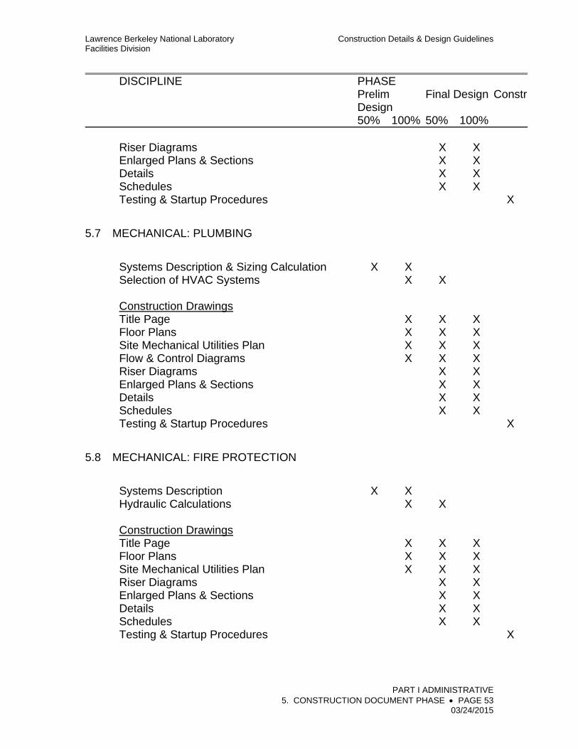
Lawrence Berkeley National Laboratory Construction Details & Design Guidelines Facilities Division
PART I ADMINISTRATIVE 5. CONSTRUCTION DOCUMENT PHASE PAGE 53 03/24/2015
DISCIPLINE PHASE Prelim
Design Final Design Constr
50% 100% 50% 100% Riser Diagrams X X Enlarged Plans & Sections X X Details X X Schedules X X Testing & Startup Procedures X
5.7 MECHANICAL: PLUMBING
Systems Description & Sizing Calculation X X Selection of HVAC Systems X X Construction Drawings Title Page X X X Floor Plans X X X Site Mechanical Utilities Plan X X X Flow & Control Diagrams X X X Riser Diagrams X X Enlarged Plans & Sections X X Details X X Schedules X X Testing & Startup Procedures X
5.8 MECHANICAL: FIRE PROTECTION
Systems Description X X Hydraulic Calculations X X Construction Drawings Title Page X X X Floor Plans X X X Site Mechanical Utilities Plan X X X Riser Diagrams X X Enlarged Plans & Sections X X Details X X Schedules X X Testing & Startup Procedures X

Lawrence Berkeley National Laboratory Construction Details & Design Guidelines Facilities Division
PART I ADMINISTRATIVE 5. CONSTRUCTION DOCUMENT PHASE PAGE 54 03/24/2015
DISCIPLINE PHASE Prelim
Design Final Design Constr
50% 100% 50% 100%
5.9 MECHANICAL: SITE UTILITIES
Systems Description X X Hydraulic Calculations X X Construction Drawings Title Page X X X Site Mechanical Utilities Plan X X X Enlarged Plans & Sections X X Details X X Equipment Schedules X X
5.10 ELECTRICAL
Systems Description X Evaluation of Existing Utilities Interconnection
Points X
Value Engineering and Feasibility Studies X Life Cycle Cost Analysis X Electrical Short Circuit Study X X X Voltage Drop Study (If Required) X X X Electrical Load Analysis X X X X X Feeder Cable Sizing X X X Lighting Calculations X X X X Breakers and Protective Relays Coordination Study X X X Testing & Startup Procedures X X Incident Energy Calculations at:
all Electrical Equipment per NFPA 70E and IEEE 1584 Standards
X X X
Equipment and Panel Schedule
X X X
Construction Drawings General Notes, Symbols, Abbreviations X X X Site Electrical Utilities Plan X X X X Electrical Power Distribution System: Single-Line Diagrams X X X X Motor Control Center One-Line Diagram X X X
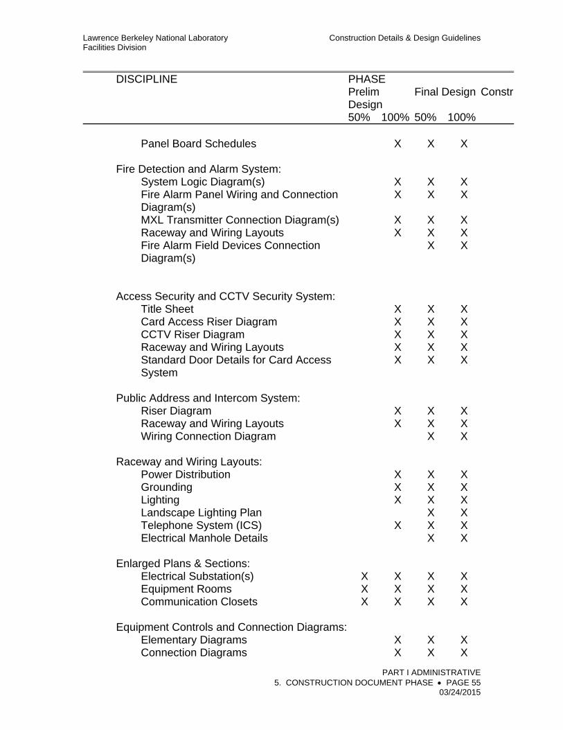
Lawrence Berkeley National Laboratory Construction Details & Design Guidelines Facilities Division
PART I ADMINISTRATIVE 5. CONSTRUCTION DOCUMENT PHASE PAGE 55 03/24/2015
DISCIPLINE PHASE Prelim
Design Final Design Constr
50% 100% 50% 100% Panel Board Schedules X X X Fire Detection and Alarm System: System Logic Diagram(s) X X X Fire Alarm Panel Wiring and Connection
Diagram(s) X X X
MXL Transmitter Connection Diagram(s) X X X Raceway and Wiring Layouts X X X Fire Alarm Field Devices Connection
Diagram(s)
X X
Access Security and CCTV Security System: Title Sheet X X X Card Access Riser Diagram X X X CCTV Riser Diagram X X X Raceway and Wiring Layouts X X X Standard Door Details for Card Access
System X X X
Public Address and Intercom System: Riser Diagram X X X Raceway and Wiring Layouts X X X Wiring Connection Diagram X X Raceway and Wiring Layouts: Power Distribution X X X Grounding X X X Lighting X X X Landscape Lighting Plan X X Telephone System (ICS) X X X Electrical Manhole Details X X Enlarged Plans & Sections: Electrical Substation(s) X X X X Equipment Rooms X X X X Communication Closets X X X X Equipment Controls and Connection Diagrams: Elementary Diagrams X X X Connection Diagrams X X X

Lawrence Berkeley National Laboratory Construction Details & Design Guidelines Facilities Division
PART I ADMINISTRATIVE 5. CONSTRUCTION DOCUMENT PHASE PAGE 56 03/24/2015
DISCIPLINE PHASE Prelim
Design Final Design Constr
50% 100% 50% 100% Control Panels-Assembly and Wiring
Diagram X X
Relay Panels-Assembly and Wiring Diagram
X X
Construction Details: Standard Installation Details X X Grounding Connections X X Special Equipment X X Lighting Fixtures Schedule X X X Sequence of Operations X X
5.11 ENERGY MANAGEMENT
Code Compliance Documentation Proposed Energy Conservation Measures X Energy Conservation Report X Estimate of Annual Energy Consumption X
9. California Energy Code Certification.
a. The RDP shall ensure that designs of new buildings and designs of alterations to existing buildings in which the space is heated or cooled comply with the California Code of Regulations, Title 24; Part 6, California Energy Code. Refer to CDDG, Part II, “Energy Efficiency,” for additional information. The University, acting as the enforcement agency, is required to independently check the designs and certify that they are in compliance with the code.
b. With the 50-percent-completed submittal, the RDP shall submit documentation, on appropriate California Energy Commission forms, certifying that the design complies with the code and CDDG. The RDP shall submit a complete performance approach computer simulation Title 24 energy compliance for University review. Process loads shall be clearly identified and implemented as allowed by California Code of Regulation Title 24, Part 6. The RDP shall correct any non-complying aspect of the design, including the energy compliance approach.

Lawrence Berkeley National Laboratory Construction Details & Design Guidelines Facilities Division
PART I ADMINISTRATIVE 6. BIDDING & CONSTRUCTION PAGE 57 03/24/2015
6. BIDDING & CONSTRUCTION
BIDDING PHASE
The RDP shall work with the University’s Representative in the following capacity:
1. Pre-qualification Process: Assist the University’s Representative in identifying an appropriate bidder pre-qualification process if one is required.
2. Pre-Bid Site Visit: Attend a pre-bid site visit conducted by the University with potential bidders to help identify questions that bidders may raise during the bidding phase.
3. Bidder’s Inquiries: The RDP shall respond to technical inquiries and refer contract questions to the University’s Representative. All questions shall be in writing.
4. Addenda: For preparation of addenda items, refer to “Addenda” section, below.
CONSTRUCTION PHASE
The presence of University professional staff does not relieve the RDP from performing the services required by the Agreement. Reviews and approvals of the contract documents, such as shop drawings and submittals, during the construction phase shall remain the responsibility of the RDP.
1. Construction Meetings
a. Pre-Construction Meeting: All parties involved in the Project, including the RDP, the Subcontractor, and the University’s Representative, shall meet to discuss Project scheduling and to establish working relationships.
b. Construction Meetings: Construction meetings shall be held at the Project site on a weekly basis, or as determined, and shall be attended by the Subcontractor’s top field supervisors, the RDP’s representatives, and the University’s Representative. The minutes of these meetings shall be prepared by the University’s Representative or as determined in the RDP Agreement.
c. Record Drawings: The RDP shall review the Subcontractor’s Record Drawings prior to or immediately following each weekly construction meeting to ensure that the Subcontractor’s work is in compliance with the Record Drawings. The RDP shall initial any changes to the Record Drawings made by the Subcontractor.

Lawrence Berkeley National Laboratory Construction Details & Design Guidelines Facilities Division
PART I ADMINISTRATIVE 6. BIDDING & CONSTRUCTION PAGE 58 03/24/2015
2. Inspection
a. Provide technical direction to, and interpretation of, the Contract Documents for inspectors and advise these inspectors of all decisions rendered.
b. Review inspection reports submitted by these inspectors and any reports furnished by others who may be retained or employed by the University to review the work. Issue any recommendations that, based on the evaluation of the report data, are deemed necessary to obtain compliance with the requirements of the contract documents.
3. Duties of the Project Inspector (designated by the University)
a. Be responsible for milestone inspections (spot checks) to assess compliance with the requirements of the contract documents, applicable codes, and Facility standards.
b. Prepare a written report following each milestone inspection. The inspector shall notify the RDP when work that does not comply with applicable codes, Facility standards, or the contract document requirements is observed in the field. Observed instances of noncompliance shall be noted in the inspector’s report.
c. Comment in subsequent inspector’s reports on whether or not instances of noncompliance have been corrected.
d. Participate in final inspections.
e. Assist the RDP in reviewing test and inspection results from testing laboratories. If the University contracts for specialty inspection services, the inspector shall report the results of these inspections to the RDP also.
f. Not authorized to deviate from the contract documents unless approved in writing by the RDP and the Facilities Engineering Department.
g. Not authorized to advise or issue directions to the Subcontractor regarding any aspect of the construction means, methods, techniques, sequences, or procedures or regarding safety programs in connection with the Project.
4. Materials Testing: During the bidding phase, and based upon the RDP’s recommendations, the University may contract with soils and materials testing laboratories.

Lawrence Berkeley National Laboratory Construction Details & Design Guidelines Facilities Division
PART I ADMINISTRATIVE 6. BIDDING & CONSTRUCTION PAGE 59 03/24/2015
5. Materials/Color Schedule and Materials Boards: Revise and update the materials/color schedule and materials boards, which were prepared during the design development phase, as necessary to reflect the actual manufacturers’ products that have been submitted by the Subcontractor and approved for use on the Project. Provide to the Project Manager for University’s files and use.
6. Punch List: Inspect the Project with the University’s Representative when notified by the University’s Representative in accordance with the subcontract that the Project is substantially complete, and again when notified that the Project is fully complete. Compile a punch list indicating any lack of compliance with contract document requirements and submit to the University’s Representative. Include a timetable for any corrective work to be done by the Subcontractor. The RDP may not advise acceptance of the Project as fully complete until all punch list items and other items required by the contract documents have been fully completed.
7. Final Approval and Acceptance Inspection
a. The RDP shall review the Subcontractor’s Record Drawings, guarantees, and operating data to access compliance with the contract document requirements.
b. The RDP shall conduct the final acceptance inspection of the Project with the inspector and the Project Manager and shall advise the University of acceptability of the work performed by the Subcontractor.
8. Record Drawings (As-Builts)
Record Drawings shall show the As-Built conditions of the work. They shall include the contract drawings, Subcontractor prepared shop drawings, Subcontractor prepared design drawings, and Subcontractor prepared layout drawings.
The Record Drawings, or As-Built Drawings, shall be revisions of the original contract drawings to include all revisions and changes made during construction as recorded by the Subcontractor “Red Line” during the course of the work. Merely supplementing the contract drawings with Change Orders and Field Directive documents stamped “AS-BUILT” is not acceptable. All Change Orders, Field Directives, RFI that resulted in field changes must be incorporated into the original contract drawings, including the revision of the CAD electronic files for the Drawings, to reflect a true “As-Built” condition. For Drawings not originally created as CAD electronic files, the original, together with as-built information, shall be scanned into electronic file

Lawrence Berkeley National Laboratory Construction Details & Design Guidelines Facilities Division
PART I ADMINISTRATIVE 6. BIDDING & CONSTRUCTION PAGE 60 03/24/2015
format (PDF) for submittal as a Record Drawing. All Drawings shall show the name and stamp of the RDP responsible for the work. Record Drawings shall be submitted both on electronic media as described under “Drawing Submittals” section, below, and as reproducible drawings as defined in the Architect/Engineer Agreement.
The electronic files and plots shall be labeled “RECORD DRAWING - AS-BUILT” with the appropriate date. In addition to the as-built contract Drawings, provide to the University all final as-built Subcontractor prepared shop drawings, design drawings, submittal drawings, and layout drawings. Provide one (1) copy of the CAD electronic files as described under “Drawing Submittals” section, below. In addition, one set of original plots on reproducible print with wet stamp by RDP shall be provided for all record drawings.
Provide no less than three (3) copies of approved sets of all documentation for Submittals, Catalog Data, and Operating and Maintenance Manuals. Refer to the Contract Documents for the exact number of sets to provide for a specific project.
9. RDP Design Warranty Services: As a basic service included with the design services, the RDP shall review the work at 6 months and 11 months after Substantial Completion, and shall submit written recommendations to the University for the correction of any deficiencies.
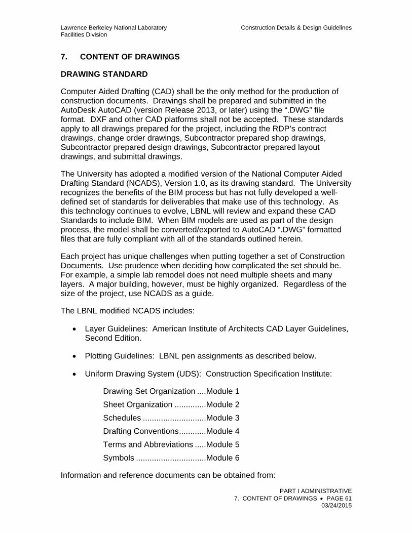
Lawrence Berkeley National Laboratory Construction Details & Design Guidelines Facilities Division
PART I ADMINISTRATIVE 7. CONTENT OF DRAWINGS PAGE 61 03/24/2015
7. CONTENT OF DRAWINGS
DRAWING STANDARD
Computer Aided Drafting (CAD) shall be the only method for the production of construction documents. Drawings shall be prepared and submitted in the AutoDesk AutoCAD (version Release 2013, or later) using the “.DWG” file format. DXF and other CAD platforms shall not be accepted. These standards apply to all drawings prepared for the project, including the RDP’s contract drawings, change order drawings, Subcontractor prepared shop drawings, Subcontractor prepared design drawings, Subcontractor prepared layout drawings, and submittal drawings.
The University has adopted a modified version of the National Computer Aided Drafting Standard (NCADS), Version 1.0, as its drawing standard. The University recognizes the benefits of the BIM process but has not fully developed a well-defined set of standards for deliverables that make use of this technology. As this technology continues to evolve, LBNL will review and expand these CAD Standards to include BIM. When BIM models are used as part of the design process, the model shall be converted/exported to AutoCAD “.DWG” formatted files that are fully compliant with all of the standards outlined herein.
Each project has unique challenges when putting together a set of Construction Documents. Use prudence when deciding how complicated the set should be. For example, a simple lab remodel does not need multiple sheets and many layers. A major building, however, must be highly organized. Regardless of the size of the project, use NCADS as a guide.
The LBNL modified NCADS includes:
Layer Guidelines: American Institute of Architects CAD Layer Guidelines, Second Edition.
Plotting Guidelines: LBNL pen assignments as described below.
Uniform Drawing System (UDS): Construction Specification Institute:
Drawing Set Organization .... Module 1
Sheet Organization .............. Module 2
Schedules ............................ Module 3
Drafting Conventions ............ Module 4
Terms and Abbreviations ..... Module 5
Symbols ............................... Module 6
Information and reference documents can be obtained from:

Lawrence Berkeley National Laboratory Construction Details & Design Guidelines Facilities Division
PART I ADMINISTRATIVE 7. CONTENT OF DRAWINGS PAGE 62 03/24/2015
National Institute of Building Sciences (NIBS) 1090 Vermont Ave. N.W., Suite 700 Washington D.C. 20005-4905 Website: http://www.nationalcadstandard.org/
DRAWING SUBMITTALS
All drawing CAD files shall be submitted on compact disks (CDs). Two (2) copies are required. Each copy and each disk shall be fully labeled with the project name, contract number, date, names and contact information for the entity(ies) responsible for preparation and submittal of the files and disks, and the sequence number of the disk in the set. Compressed files are not allowed. Provide an index of electronic file drawings for each CD submitted. Unused layers and blocks shall be purged from the drawing file. Electronic file CAD drawings must be identical to the required hardcopy submittals while adhering to the LBNL CAD Standards.
LEGAL USE
The Subcontractor’s use of CAD files shall be in accordance with Division 01 of the Specifications. Submittal of the drawing CAD files shall be considered a legal submittal of any fonts, menus, line types, symbols (blocks or entities), and any proprietary information incorporated into the drawings. If symbols (blocks or entities) or other information is copyrighted, LBNL has the right to use and to distribute all such information at no cost or liability.
DRAWING MEDIA
Preferred media for interim phases and submittals is white bond paper. Final reproducible drawing media shall be white bond paper when required by the PDR. Plots, prints, and copies submitted at all phases of the project must be reproducible in clear, crisp detail.
CAD LAYERS
Use the layer naming conventions listed in the AIA layer guidelines. Scale the complexity of the layers to the scale of the project. For example, for only one type of wall on a single story call it “A-WALL”; not “A-WALL-FULL.”
PLOTTING GUIDELINES
DRAWING SET ORGANIZATION
Organize drawings in a logical sequence that relates to the disciplines preparing the documents. Use the subset sequence listed in Section 1.3 Sheet Identification.
SHEET IDENTIFICATION
Lawrence Berkeley National Laboratory Construction Details & Design Guidelines Facilities Division
PART I ADMINISTRATIVE 7. CONTENT OF DRAWINGS PAGE 63 03/24/2015
Use the standard sheet identification formats in Module 1 UDS. When combining drawings on the same sheet (e.g., plans and elevations), use the most prominent drawing for your sheet identification.
ELECTRONIC FILE NAMING and PROJECT FOLDERS
Use the standard file/folder naming conventions in Module 1 UDS. Scale the complexity of the files/folders to the scale of the project. Keep as simple as possible. Each respective drawing file shall be named to relate to its sheet number within the plan set.
SHEET SIZE
Sheet sizes shall be coordinated with the University’s Representative. The preferred sheet size is ANSI D 22”x34”. ANSI E 34”x44” with approval by the Facilities Engineering Department is acceptable on larger projects. Refer to Module 2 UDS for more information.
SHEET LAYOUT
Drawing Sheet
1. Use ANSI D size 22” x 34” or ANSI E 34”x44” with approval by the Facilities Engineering Department.
2. Title Block
Locate the Title Block for all drawings on the right edge of the drawing. For the space location and other required data refer to “Drawing Sheets – Title Block,” RD4.16 of the CDDG, Volume 4 - RDs. The project title and drawing file numbers shall appear on all construction documents and in the Title Block on all Conceptual Design and Preliminary Design drawings as well. Sheet numbers are established by the RDP firm. The date on the drawings shall be the day the drawings are submitted to the University for printing of bid sets.
3. Scales
Drawings shall be made to the following scales:
a. Plans and elevations: 1/8", 1/4" or 1/2" = 1’-0”
b. Site plans: 1" = 20’ or larger
c. Details: 3/4" = 1’-0” or larger
d. Font sizes shall be a minimum of 1/16” high when the full size drawing is reduced by half.
4. Site Plans
Include in all site plan drawings, including mechanical and electrical, LBNL grid lines at 100-foot intervals, referenced by coordinates.

Lawrence Berkeley National Laboratory Construction Details & Design Guidelines Facilities Division
PART I ADMINISTRATIVE 7. CONTENT OF DRAWINGS PAGE 64 03/24/2015
Wherever possible establish new facility locations in terms of grid coordinates.
5. Drawing Orientation
Orient identically all plan views on all drawings of a project, with north preferably to top of sheet. On each sheet, include a north arrow indicating True North. For remodeling projects match north direction with north on the original project drawings.
6. RDP Identification
Identify the RDP in the title block. Include firm name, address, telephone number, required professional seals, signatures, and registration numbers. Drawings prepared by a consultant to the RDP shall include the same information on both firms. Refer to “Drawing Sheets – Title Block,” RD4.16 of the CDDG, Volume 4 - RDs, for a sample Title Block.
7. Draw details in an easily readable size.
8. Provide an adequate identifying legend and list of abbreviations on each set of construction documents for all symbols and abbreviations used. Refer to “Standard LBNL Abbreviations Equipment/Facility Types,” RD7.4 of the CDDG, Volume 4 - RDs.
9. Include a LBNL key plan showing location of project site.
10. Make lettering 1/8" minimum height and suitable for microfilming.
11. For Drawing Numbering, refer to “Drawing Management,” RD3.9 of the CDDG, Volume 4 - RDs.
EQUIPMENT IDENTIFICATION
All new equipment and panels shall be assigned numbers from the LBNL Equipment Numbering System. The numbers shall be provided by the University and shall be indicated on the drawings, schematics, and as-built drawings.
REVIEW DRAWINGS
Drawings submitted for review shall be identified with numbered revisions, the date of submittal, and the type of submittal (e.g., “Final Design 100% review submittal”).
BID DRAWINGS
The final version of the Final Design drawings incorporating all review comments and accepted by the University as complete for bid shall have all dates coordinated to the final acceptance date. All revision designations made during the review submittal process are to be removed. Drawings are to be labeled Revision A, “ISSUED FOR BID” and shall have the same date of issuance.

Lawrence Berkeley National Laboratory Construction Details & Design Guidelines Facilities Division
PART I ADMINISTRATIVE 7. CONTENT OF DRAWINGS PAGE 65 03/24/2015
DRAWINGS ISSUED DURING CONSTRUCTION
Revised versions of the Bid drawings issued after release of the subcontract are to be tracked as lettered revisions. The revision log on the title block shall be filled out with revision letter, date of issuance, and description. Additionally, the LBNL Drawing Number shall be amended to add the revision letter to the end.
If a conformed set is created which incorporates clarifications and changes made during the bid process, all revised sheets are to be labeled per above with the designation “CONFORMED SET ISSUED FOR CONSTRUCTION.” All revision issues are to be wet stamped and signed by RDP.
RECORD DRAWINGS
The RDP shall prepare as-built record drawings from the most recently revised set of drawings incorporating field mark-ups provided by the Subcontractor showing the work actually accomplished. The record drawings shall include all revisions, change orders, clarifications, field changes, adjustments, variances, substitutions, and deletions that were made during the course of the work.
The record drawings shall be prepared as AutoCAD drawing files and identified using the next revision letter for the sheet or "_" if the sheet was not revised since being issued for bid. Each drawing shall have the designation “AS-BUILT RECORD DRAWINGS” in the revision title block. A final hard copy and the electronic CAD file and a PDF file on electronic media of each drawing shall be provided to the University’s Representative within 30 days after transfer of the Project field mark-ups to the RDP.
a. As required in the Architect/Engineer Agreement, the RDP shall provide reproducible Record Documents to the University. Any revisions or changes that have been made during construction shall be incorporated in the Record Documents. During construction, the RDP shall review all revisions and changes and shall approve the set of drawings and specifications maintained by the Subcontractor prior to the preparation of the final Record Documents or As-Builts.
1) The Revision log shall be updated to reflect Revision "A": As-Built – Record Drawings.
2) The As-Built Record Drawings shall only show current conditions and all design requirements/activities shall be removed.
3) The As-Built Record Drawings shall not show clouded areas to flag as-built changes from the original design.
4) The As-Built Record Drawings shall not show removed, demolished equipment and systems, etc.
5) The As-Built Record Drawings shall continue to be in accordance with

Lawrence Berkeley National Laboratory Construction Details & Design Guidelines Facilities Division
PART I ADMINISTRATIVE 7. CONTENT OF DRAWINGS PAGE 66 03/24/2015
the LBNL Construction Standards and Design Guidelines (CDDG) requirements per the contractual Project Design Requirements (PDR).
b. Mechanical (HVAC), Plumbing, and Controls drawings shall include, but not
be limited to, the following items:
1) An actual air balance report CFM (cubic feet per minute) for each air outlet and each air inlet on all drawings.
2) An added schedule for each fan motor indicating (1) the actual ampere measured in each conductor, (2) the full-load ampere noted on the motor’s nameplate, (3) the service factor noted on the motor’s nameplate, (4) the motor voltages noted on the motor’s nameplate, and (5) the actual voltage between each conductor: for example, A to B, A to C, and B to C on single-winding three-phase motors.
3) The final sequence for each mechanical system.
4) Revisions of each schedule in the original contract documents reflecting the actual equipment installed (by manufacturer’s name and model number), actual locations of the equipment installed, and all other revisions to the equipment schedule.
5) Specific locations of each diffuser (exhaust & supply), specific location of the field installed controllers for the operation and control of all mechanical systems, FMCS Field Processing Unit (FPU), etc.
c. Electrical Record Documents shall include, but not be limited to, the following items:
1) A finalized breakers and protective relays coordination study incorporating actual settings, ratings, transformer and feeder data, etc.
2) Final incident energy calculations including code required labels.
3) Locations of each electrical panel, power outlets, power strip, speakers, telephone jack, data jack, and all field located electrical discipline items such as light switches , emergency light, exit sign, thermostat, elevator push button, handicap push button, card access pad, touch key pad, power pole drop, motion detector, etc. The LBNL identification of the system shall be used throughout the drawing set.
4) As-built electrical panel schedule, including the exact locations of all circuit breakers, type, sizes, etc. The LBNL identification of the panel schedule system shall be used throughout the drawing set for the as-built update.

Lawrence Berkeley National Laboratory Construction Details & Design Guidelines Facilities Division
PART I ADMINISTRATIVE 7. CONTENT OF DRAWINGS PAGE 67 03/24/2015
5) Electrical single-line diagram update.
3) A CD with all study and calculations information and the SKM or ETAP software project files.
d. Fire Alarm and Fire Sprinkler Record Documents shall include, but not be limited to, the following items:
1) Locations of each fire alarm panel, smoke detector, fire alarm bell, fire door release, and all field located fire alarm components such as smoke detector, fire alarm bell, fire door release, fire alarm panel, fire alarm pull, fire alarm box, strobes and horns, etc. The LBNL identification of the system shall be used throughout the drawing set.
2) Sizing calculation to determine the power requirement for the fire alarm system shall be finalized to the as-built condition showing the available capacity for future expansion of the system.
3) Fire sprinkler drawings shall show the actual locations of the sprinkler heads, actual sizes of the pipes, valves, flow sensors, and all field installed fire sprinkler components.
SECTIONS & DETAILS
Sections and details shall be clearly referenced on the plans and elevations, and wall section cuts shall be indicated on the plans and elevations and referenced on the building sections. Cross-references from details/sections back to plans and elevations are required. Indicate clearly where typical conditions begin and end, and where non-typical conditions occur. Carry building sections completely through the building or buildings; indicate beginning and end of building sections clearly on plans.
ROOM NUMBERS
Number each interior room and outdoor space on all Drawings, including closets, chases, storage areas, stairs, patios, covered walkways, mechanical equipment enclosures, and other similar spaces. Provide a Room Finish Schedule that indicates the name, number, and all finishes to be provided for that space. Provide an appropriate legend as required to define codes and abbreviations. Ceiling heights may be referenced on finish legend or on the reflected ceiling plans.
The RDP shall coordinate with the University’s Representative to insure room numbering in accordance with University standards.
DOORS AND FRAMES
Doors and frames shall be numbered on the construction drawings with the

Lawrence Berkeley National Laboratory Construction Details & Design Guidelines Facilities Division
PART I ADMINISTRATIVE 7. CONTENT OF DRAWINGS PAGE 68 03/24/2015
rooms they serve. Therefore, the primary door to Room 100 shall be Door 100; the secondary entry to that space shall be Door 100A, etc. Pairs of doors without a fixed mullion shall be treated as one door number; separated pairs shall have two door numbers. Indicate direction of door swings on plan. Provide a complete door and frame schedule. Express fire ratings in time, rather than A, B, C, etc. Provide elevations of all door and frame types (including borrowed lights and transoms) with typical and critical dimensions. Indicate typical hardware heights.
WINDOWS
Windows shall be referenced by a suitable mark on the plan to a Window and Opening Schedule. Provide elevations of window and opening types with typical and critical dimensions. Clearly reference details. Indicate special glazing conditions.
ABBREVIATIONS AND SYMBOLS
Abbreviations shall only be used where the entire word will not fit. Symbols shall be explained in a legend. Consultants shall tailor the legend for the particular project and insist all technicians working on the project are familiar with the conventions. Refer to Modules 5 and 6 UDS for a listing of standard abbreviations and symbols.
Lawrence Berkeley National Laboratory Construction Details & Design Guidelines Facilities Division
PART I ADMINISTRATIVE 8. MECHANICAL, ELECTRICAL & STRUCTURAL CALCULATIONS PAGE 69 03/24/2015
8. MECHANICAL, ELECTRICAL, AND STRUCTURAL CALCULATIONS
CALCULATIONS
All calculations shall be checked and stamped by an engineer registered in the applicable discipline. The calculations shall clearly list all design criteria, assumptions, and references used. The calculations shall be arranged in a clear manner including schematic diagrams and spreadsheets where necessary.
Engineering calculations shall be sufficient to ensure compliance with all applicable codes and design standards. Submitted calculations shall include, but not be limited to:
1. Structural Calculations (for detailed requirements refer to CDDG, Part II, “Design Requirements”).
a. Structural drawings shall be accompanied by computations, stress diagrams, and other pertinent data and shall be complete to the extent that calculations for individual structural members can be readily interpreted.
b. The computations shall be prefaced by a statement outlining the basis for the structural design and indicating the manner in which the proposed building shall resist vertical loads and horizontal forces.
c. The computations shall be sufficiently complete to establish that the structure shall resist the loads and forces prescribed by CCR regulations and CDDG, Part II, “Design Requirements.”
d. Assumed safe bearing pressures on soils and ultimate strengths of concrete shall be given in computations and noted on plans.
e. Where unusual conditions occur, additional data as is pertinent to the work shall be submitted.
2. Mechanical Calculations
a. Heating and cooling load calculations.
b. Psychometric charts and air conditions.
c. Fan and coil sizing calculations and selection data.
d. Sizing calculations and selection data for chillers, boilers, cooling towers, heat exchangers, packaged air conditioners, etc.
e. Ductwork and pipe sizing calculations – include flows per room or

Lawrence Berkeley National Laboratory Construction Details & Design Guidelines Facilities Division
PART I ADMINISTRATIVE 8. MECHANICAL, ELECTRICAL & STRUCTURAL CALCULATIONS PAGE 70 03/24/2015
coil, sizing method used, and pressure drops.
f. Domestic/industrial hot water sizing calculations, including pump sizing.
g. Structural and seismic calculations for equipment supports (may be submitted with structural calculations).
h. CCR Title 24 Energy Efficiency Compliance calculations on standard California Energy Commission (CEC) forms. Provide performance approach computer simulation in conformance with Title 24.
i. Energy efficiency checklist (refer to CDDG, Part II, “Energy Efficiency”).
3. Electrical Calculations
a. Summary of electrical loads used in calculating transformer size.
b. Fault interruption calculations (using SKM or ETAP software).
c. Breaker and relay protection coordination (using SKM or ETAP software).
d. Incident energy calculations (using SKM or ETAP software).
e. Point-by-point lighting analysis for all typical rooms and corridors.
f. CCR Title 24 Energy Efficiency Compliance calculations on standard CEC forms.
g. Energy efficiency checklist (refer to CDDG, Part II, “Energy Efficiency”).
LIFE CYCLE COST ANALYSIS
Discuss the following systems based on life cycle cost analysis.
1. Three types of air handling systems.
2. Three cooling plants.
3. Two heating plants.
4. Two domestic/industrial hot water systems (not required if natural gas).
5. Two roof U-values (range of 0.05 to 0.03).

Lawrence Berkeley National Laboratory Construction Details & Design Guidelines Facilities Division
PART I ADMINISTRATIVE 8. MECHANICAL, ELECTRICAL & STRUCTURAL CALCULATIONS PAGE 71 03/24/2015
6. Two wall U-values (range of 0.10 to 0.05).
7. Three glazing alternatives (single vs. double, exterior shading, high performance glazing, etc.).
8. Any energy efficiency measure identified as “Required” in CDDG, Part II, “Energy Efficiency,” that is not to be used in this project.
In some small buildings and small remodeling projects, the above-mentioned life cycle cost analysis may not be practical. If RDP feels that this is the case, contact the University’s Representative for possible exemption.
Contact the University’s Representative for study life, utility rates, discount factors, escalation factors, and benefit-to-infrastructure values.

Lawrence Berkeley National Laboratory Construction Details & Design Guidelines Facilities Division
PART I ADMINISTRATIVE 9. SPECIFICATIONS PAGE 72 03/24/2015
9. SPECIFICATIONS
GENERAL NOTES
LBNL Facilities Division shall provide the following to all RDPs for reference only.
For the final submittal, the RDP shall submit in addition: one (1) full size set of reproducible originals, wet stamped and signed; one (1) unbound set of specifications, wet stamped and signed; and drawing and specification files on writeable CDs. A list of file names with a one-sentence description of each shall be included with the disks.
For submission requirements for electronic CAD files, refer to “CAD Standards” RD3.10 of the CDDG, Volume 4 - RDs.
TECHNICAL SPECIFICATIONS REVIEW
Refer to requirements listed under Project Deliverables table (this document) for further detail. Technical Specifications are to be submitted to the University’s Representative who shall coordinate the review with in-house Staff and for external independent review.
GENERAL CONDITIONS & DIVISIONS 02-41The following guidelines are to assist the RDP and Consultants in coordinating the General Conditions with Specifications Divisions 02-41.
1. The requirements of the Specifications must be consistent with terms of the Agreement and the General Conditions. Additions may be included in the Supplemental Conditions. Requested changes shall be submitted to the University’s Representative for review and approval.
2. Administrative requirements, procedural requirements, and temporary facilities applying to all the work are to be covered in Division 01 General Requirements. Do not rewrite or duplicate in a technical section any requirement specified, or information already provided in, the General Conditions or Division 01 General Requirements (e.g., soils report, testing, clean-up, repair of existing work, etc.). Provide only a reference to Division 01 to the corresponding section, “For...., refer to Section 01xxxx, Section Title”.
3. No paragraph at the beginning of sections in Divisions 02-41 should state: “The General Conditions and General Requirements are a part of this section.” or “The General Conditions are a part of this Division.”
4. Any general requirements in Divisions 02-41 should apply only to the work of that Division and serve as extensions of Division 01 General Requirements. A method of incorporating Division 01 requirements

Lawrence Berkeley National Laboratory Construction Details & Design Guidelines Facilities Division
PART I ADMINISTRATIVE 9. SPECIFICATIONS PAGE 73 03/24/2015
would be: “In addition to requirements of Section 01xxxx, Section Title.” If the general requirement is applicable to the entire project, it should be included in Division 01. The following are exceptions:
a. Those portions of Divisions 02-41 containing general requirements that are unique to specific work (e.g., mechanical or electrical) require particular coordination of content to avoid repetition, omissions, or conflict with Division 01.
b. Requirements for strength and physical characteristics of materials and components or standards of workmanship for manufacture and field installation are to be located in appropriate sections of Divisions 02-41.
5. Divisions 22, 23, 26, 27, 28, & 33 General Provisions
a. General Provisions, if provided in the above Divisions, must apply only to that Division.
6. Do not include copyright language on any of the documents.
SPECIFICATIONS DIVISIONS 02-41
The RDP shall prepare all technical specification sections required by Divisions 02-41 except selected sections that shall be provided by the University.
LBNL Master Specifications edited by the RDP: The RDP shall review the sections, edit them to suit the project, and submit a marked-up copy (tracked changes) to the University for review and approval of edits. The edited specification sections shall not be incorporated into the construction documents without University approval.
LBNL Master Specifications edited by the University: The RDP shall review the sections and report to the University’s Representative any conflicts or omissions. The RDP shall not modify or change these sections without the express approval of the University.
To assist in the preparation of the Specifications, the University has prepared the following guidelines in accordance with policies outlined in the University’s Facilities Manual and in conjunction with the CSI format.
1. Specifications shall be written for a two-party contract.
a. Write sections for “Traditional University-Subcontractor Contract.”
b. The contract is with the General Subcontractor; therefore, the Specifications must not be written to assign responsibility for work to the various subcontractors or require the subcontractors to

Lawrence Berkeley National Laboratory Construction Details & Design Guidelines Facilities Division
PART I ADMINISTRATIVE 9. SPECIFICATIONS PAGE 74 03/24/2015
perform tasks. The General Subcontractor assigns the work to his subcontractors. Do not write statements such as: “The Mechanical Subcontractor shall be responsible for….“.
c. Do not give instructions or assign responsibility to a third party (e.g., inspectors, manufacturers, material vendors, or suppliers).
d. Always direct comments to the Subcontractor, such as “Subcontractor shall provide manufacturer’s inspection or testing” or “Subcontractor shall obtain written certification from manufacturer.” Do not make reference to subcontractors or trades. Do not assign the work.
e. If the word “Inspector” is used, it must be defined. The General Conditions do not define it.
f. Only the Subcontractor shall supervise the work. “Continuous” inspection is difficult to achieve and subjects the University to possible damages from the Subcontractor if something is missed.
g. Only the University’s Representative is authorized to approve work, materials, etc.; the Soils Engineer or any other such person performs tests and reports results to the University.
h. Do not use “approved substitution” or “approved manufacturer.” The General Conditions do not define it. The word “approved” gives the impression that all manufacturers are acceptable. Specification Section 010000, General Requirements, under “Specified Items – Substitutes”, defines only the first manufacturer as acceptable without submittal approval process.
2. University’s Representative Approval
a. The University’s Representative may “approve,” “select,” or “request” but may not “direct” or “instruct” Subcontractor unless it is intended that the University’s Representative shall be on-site directing or instructing the Subcontractor exactly how to perform the work.
1) Do not make reference to consulting engineers, landscape architects, etc. for approval. The University’s Representative is the only entity who may accept, reject, direct, approve, or disapprove the Work of the Contract.
2) Soils engineers, testing labs, and others involved in the construction process shall make “recommendations” to the University’s Representative.
Lawrence Berkeley National Laboratory Construction Details & Design Guidelines Facilities Division
PART I ADMINISTRATIVE 9. SPECIFICATIONS PAGE 75 03/24/2015
3. Submittals
a. The Subcontractor shall make all drawing submittals to the University’s Representative.
b. Do not require the Lower-tier Subcontractor or other entity to submit Drawings directly to LBNL.
4. Definitions
a. Use “University”, not “Owner,” because the University does not always own the property.
b. Use “University’s Representative,” not “Owner’s Representative,” because the duties may be performed by the Architect, a Construction Manager, or University personnel.
c. When indicating to “consult University,” use “consult University’s Representative”.
d. "Subcontract" shall be used to identify the construction contract between the University and the General Subcontractor.
e. "Subcontractor" shall be used to identify the General Subcontractor. Specifications shall not make any references to subcontractors to the General Subcontractor.
f. The following are terms and their meanings to be used in writing the Specifications.
AS DIRECTED ................ As directed by the University’s Representative.
AS REQUIRED ............... As required by applicable code requirements, good building practice, the condition prevailing, the Bidding Documents, the University, or the University’s Representative.
AS SELECTED ............... As selected by the University’s Representative.
BY OTHERS ................... Work on this project that is outside the scope of work to be performed by the Subcontractor under this Subcontract, but that shall be performed by the University, separate Subcontractors, or other means.

Lawrence Berkeley National Laboratory Construction Details & Design Guidelines Facilities Division
PART I ADMINISTRATIVE 9. SPECIFICATIONS PAGE 76 03/24/2015
EQUAL............................ Of same quality, appearance, and utility to that specified, as determined by the University’s Representative. Subcontractor bears the burden of proof of equality.
FURNISH ........................ Supply only, not install (unless required to be provided or installed elsewhere in the Bidding Documents).
INSTALL ......................... Install or apply only, not furnish.
OFF-SITE ....................... Outside the Work area, as shown on the Drawings or the property lines.
UNIVERSITY-FURNISHED/ SUBCONTRACTOR-INSTALLED To be furnished by the
University at its cost and installed by the Subcontractor as part of the Work.
PROJECT SITE .............. Geographical location of the Project.
PROVIDE ........................ Furnish and install.
SHOWN .......................... As indicated on the Drawings.
SPECIFIED ..................... As written in the Bidding Documents.
SUBMIT .......................... Submit to the University’s Representative.
5. Editions of Codes, Regulations, etc.
a. Unless otherwise specified, specific references to codes, regulations, standards, manufacturers’ instructions, or requirements of regulatory agencies, when used to specify requirements for materials or design elements, shall mean the latest edition of each.
b. Do not use references to City or County building codes and regulations. University work is not normally subject to these laws and regulations. The University may choose to build to these standards, but is not subject to their inspection or requirements.
6. Guarantees
a. The General Conditions require all items to be guaranteed for a

Lawrence Berkeley National Laboratory Construction Details & Design Guidelines Facilities Division
PART I ADMINISTRATIVE 9. SPECIFICATIONS PAGE 77 03/24/2015
period of one (1) year. Often, the Specifications require a roof or other item to be guaranteed for more than one (1) year, but the Specifications do not state what feature of the item, for example, leaks, cracks, color, etc., is to be guaranteed. The special conditions must be specified.
b. If extended guarantees are required in Divisions 02-41, the requirement shall be written as follows: Furnish to University a written guarantee for ______________ (name of item) against all defects in materials and workmanship, including without limitation against ____________________ (list detail, e.g., against warping, twisting, discoloration), for __________ (fill in number) years from date of acceptance.
Refer to Section 010000, General Requirements, under “Guarantee”, and “Attachment A Guarantee” form.
c. For Maintenance & Operations projects, list the special guarantees in the Table of Submittals in Section 010000, General Requirements, under “Submittals.
d. The guarantee period begins when the University’s Representative determines the work to be Substantially Complete, or Final Completion; whichever is earliest.
7. Special Conditions/Requirements
a. Provide lists of special conditions, requirements, and the technical section where requirements are specified. For example, if a Subcontractor is required to have a special license, to have more than one (1) year experience in installing equipment or systems, or to submit proof of any special requirement. These requirements must be added to the Supplementary Instructions to Bidders section of the Bidding Documents. In addition, bidders are informed of any special requirements they need to possess in order to have their bids considered responsive in the Bidding Documents as well as at the mandatory Pre-Bid Conference.
8. Listing of Products/Manufacturers
a. A “closed” specification limits a product to a single manufacturer or group of manufacturers. An “open” specification allows products of any manufacturer to be used if the manufacturer’s product meets the specified requirements. The University and Federal law prohibits the use of closed Specifications. Common closed specification errors are:

Lawrence Berkeley National Laboratory Construction Details & Design Guidelines Facilities Division
PART I ADMINISTRATIVE 9. SPECIFICATIONS PAGE 78 03/24/2015
1) Not using the phrase “or equal.”
2) Listing only one (1) brand plus “or equal” when there are other known brands.
3) Using wordy formats that either do not specify items or contain a multitude of words to substitute for the phrase “or equal.”
4) Using the term “approved equal” instead of “or equal.”
b. The term “or equal” is defined in Section 010000, General Requirements, under “Specified Items – Substitutes”, whereas “or approved equal” is not. Use and definition of this term is subject to the approval by the University’s Office of the President.
c. For all products, list two (2) or more manufacturers, with model or product numbers on the first product only, and followed by the words “or equal.” For example: “Manufacturers: New York Blower, Model No. _____, Buffalo Forge, or equal.”
d. Manufacturers (name and model or product number) shall be listed in the following order: the first listed sets the standard, followed by those considered to be alternate equals.
e. Listing the name, address, telephone number, etc. of one (1) manufacturer requires that the like information for all manufacturers listed be included.
f. The following are exceptions to the two (2) or more manufacturers’ requirement:
1) Critical Products
a) Brand names and model numbers of University approved products (min. three (3)). Do not use "or equal."
b) One (1) brand name and model number, to match existing.
c) One (1) brand name and model number, no substitutes. (This option has to be justified.)
2) Non-Critical Products
a) Two (2) brand names and model numbers, or equal.
b One (1) brand name and model number, no known equal.

Lawrence Berkeley National Laboratory Construction Details & Design Guidelines Facilities Division
PART I ADMINISTRATIVE 9. SPECIFICATIONS PAGE 79 03/24/2015
c) No brand names. (Use descriptive, non-proprietary specifications.)
3) If only one (1) manufacturer is known to make a specific product, you must say: “Manufacturer _____, Model No. _____, or equal (no known equal).”
a) In addition, you must write a brief performance specification detailing what is unique or “state-of-the-art” about the item which would preclude/prevent use of an alternate product.
b) Where performance or descriptive Specifications are used, they shall be made nonrestrictive. The description or performance requirements shall not use the description or performance requirements of a single manufacturer.
4) If a product must match a product in the same or adjacent space, or to match LBNL Standard (e.g., Pyrotronics XL3 Fire Alarm System or Schlage L series locksets), you must say “Manufacturer _____, Model _____, (to match existing) or (to match LBNL Standard). Do not use “or equal” or “no substitution permitted.”
g. Do not use “New” or “(N)” in describing the work in order to avoid uncertainties. The General Conditions state all products are new unless otherwise stated.
9. Phasing of Work
a. If certain phases or portions of the work require completion before the whole project is completed, then separate liquidated damages must be assigned to ensure the separate completion dates.
b. Provide the following information, if applicable.
1) Description of Work for each phase.
2) Number of calendar days to complete the Work.
3) Number of calendar days separating one phase from the previous.
4) If one phase has to be completed before the next phase can start.
5) If any of the phases run concurrently.

Lawrence Berkeley National Laboratory Construction Details & Design Guidelines Facilities Division
PART I ADMINISTRATIVE 9. SPECIFICATIONS PAGE 80 03/24/2015
10. Document Coordination
a. Coordinate Drawings and Specifications. If Specifications refer to an item on the Drawings, verify that the item is indicated (e.g., limits of construction, site fencing, parking areas, etc.).
b. Verify that all Drawings are included in the List of Drawings and the information is correct.
c. Each drawing included in the construction subcontract documents shall include a sheet number, a drawing number, a CAD file number, LBNL Project number, and the construction subcontract number. The RDP shall submit the index of drawings to the University’s Representative for assignment of LBNL drawing cataloging numbers from the Facilities Engineering Department filing system. The University’s Representative shall provide the construction subcontract number before the final review of the drawings.
11. Testing Laboratories
a. If the University is providing and paying for testing lab, so state and list types of tests to be made and method(s) required.
b. If the Subcontractor is providing and paying for testing lab, so state and list types of tests to be made and method(s) required.
12. Long-Lead Items
a. The RDP must analyze the construction schedule and make recommendations to the University’s Representative for a construction time period that takes into consideration long-lead items. Technical Sections (Divisions 02-41) may need to address submittal of purchase order during a specified time frame.
13. Asbestos or Lead
a. If asbestos and/or lead is present in or around the Project Site, Section 028300, Lead Abatement, and/or Section 028200, Asbestos Abatement, must be included in the Specifications. Master copies of these Sections shall be provided to the RDP and Consultants for mark-up of recommended changes. In the case where the University is solely responsible for Specifications related to Asbestos Removal or Asbestos Encapsulation, the RDP must provide the appropriate wording for inclusion in the Information Available to Bidders section.
14. Listing of Soils Investigation Report

Lawrence Berkeley National Laboratory Construction Details & Design Guidelines Facilities Division
PART I ADMINISTRATIVE 9. SPECIFICATIONS PAGE 81 03/24/2015
a. The Soils Report (e.g., geotechnical data) may be issued with the Documents, and is provided solely for the bidders’ convenience and does not relieve the bidders of the responsibility for determining the accuracy of the information provided. A soils disclaimer is required whenever site work requires the use of a soils investigation report. The Information Available to Bidders provides this disclaimer. If the report has a copyright, attach a letter giving permission to print the report.
15. Demolition Bid Documents (if applicable)
a. The RDP shall review existing field conditions and as-built documentation and prepare [a separate bid package][demolition drawings and specifications] for the demolition of [brief description of demolition scope]. Documents shall include limits of the work, utility disconnection points, utility relocations required to keep remaining buildings operational, temporary facilities that may be required to keep adjacent roadways and buildings functional during the demolition phase, and any repairs to remaining buildings and site improvements after demolition is complete.
b. The University shall provide a hazardous materials survey of the existing building, which shall be referenced in the demolition documents.
16. Alternates
a. Alternates shall be consistent in Section 012300, Alternates, and in Specifications, Drawings, and Bid Form.
b. The lump sum bid should cover the scope of a complete project without the need for alternate bids. Alternates may be requested, however, for the following reasons:
1) To adjust the scope of the work to keep the Contract Sum within budget, or
2) To allow a decision between two different materials or methods of different values.
3) Additive: Used to obtain the maximum work for the available budget. This method assumes that the total bid price received could be below the budget, and that the Contract Sum could be increased to match the budget figure through the execution of alternates.
4) Deductive: Used as a means to bring the total bid price within

Lawrence Berkeley National Laboratory Construction Details & Design Guidelines Facilities Division
PART I ADMINISTRATIVE 9. SPECIFICATIONS PAGE 82 03/24/2015
the budget.
d. Post-Award Alternate: A post-award alternate is an alternate that is exercisable for a stipulated period from the date of contract award. This type of alternate is used when the possibility of attaining additional funds at a date after the contract award is known or highly probable. Since the alternate is not exercised until after the award of the contract, it is not a basis of award.
e. Presentation of the alternates in the Bid Documents should include the following:
1) Identification and description of each alternate, including whether the alternate is an additive or a deductive.
2) Reference to applicable Drawings and Specification Section(s).
3) Detailed description of alternates affecting the scope of the work.
4) Summary of alternates affecting materials, methods, and reference(s) to appropriate Specification Section(s).
f. Alternate(s) shall be assigned an individual number to allow their identification in other Sections of the Bidding Documents. The Drawing(s) and Specification Section(s) shall indicate which alternates apply. The description of alternate(s) in the Specifications and their identification on the Drawings should allow the University to select any one (1) alternate, or combination of alternates.
17. Final Submittal
a. When all University required corrections have been incorporated, documents stamped by all RDPs and agencies, and the 100-percent completed Technical Specifications and Drawings have been accepted by the University’s Representative, the RDP shall provide the University with a complete set as follows:
1) Drawings: one (1) set of white bond paper reproducible originals bearing RDP’s discipline engineer certification, an agreed upon number of sets of prints, and electronic copies of the AutoCAD drawing files on CD in the correct AutoCAD format.
2) Specifications: one (1) original hardcopy and electronic copies on CD, formatted in Microsoft Word 2010 or later format.
Lawrence Berkeley National Laboratory Construction Details & Design Guidelines Facilities Division
PART I ADMINISTRATIVE 9. SPECIFICATIONS PAGE 83 03/24/2015
3) Certification Page: sign and stamp the certification page provided by the University for the Specifications.
4) Final Basis of Design (BOD) to support project commissioning process.
b. Upon completing the 100-percent final documents, the RDP shall submit to the University a letter of assurance attesting that the documents are complete and ready to bid.
SPECIFICATIONS FORMAT
The following are guidelines for the RDP and Consultants in preparing Divisions 02-41. Use Construction Specifications Institute (CSI) format and numbering system.
1. Organize, index, and number Specifications in accordance with the CSI 3-part and paragraph numbering format for construction Specifications. Automated systems such as Spec Text and MasterSpec are acceptable for use and encouraged due to their continual updating. These master systems do not relieve the RDP and Consultants of the responsibility to properly edit the Specification based on the particular project, and locally available products and methods. The preparer shall verify local conditions and research to include in the final documents products, materials, or methods that are appropriate for local usage.
PART 1 – GENERAL PART 2 – PRODUCTS PART 3 – EXECUTION
Note: If one of the above parts is not used, indicate “not used”. For example: PART 1 – GENERAL (NOT USED)
Specifications for review shall be printed on standard 8-1/2 by 11 inch paper, bound on the left with a removable binder. Final bid set shall be original, one-sided, unbound laser printed copy for final reproduction. Include electronic files with submittal.
2. Left and right margins shall be 1 inch on each side; top and bottom margins shall be 1/2 inch.
3. Do not bold, underline, or italicize in the body of the text except headings according to CSI format.
4. Headers are required on all pages of Specification Sections and other documents, such as hardware schedules. Headers shall be printed flush with the left margin, printed in capital letters, and indicate the
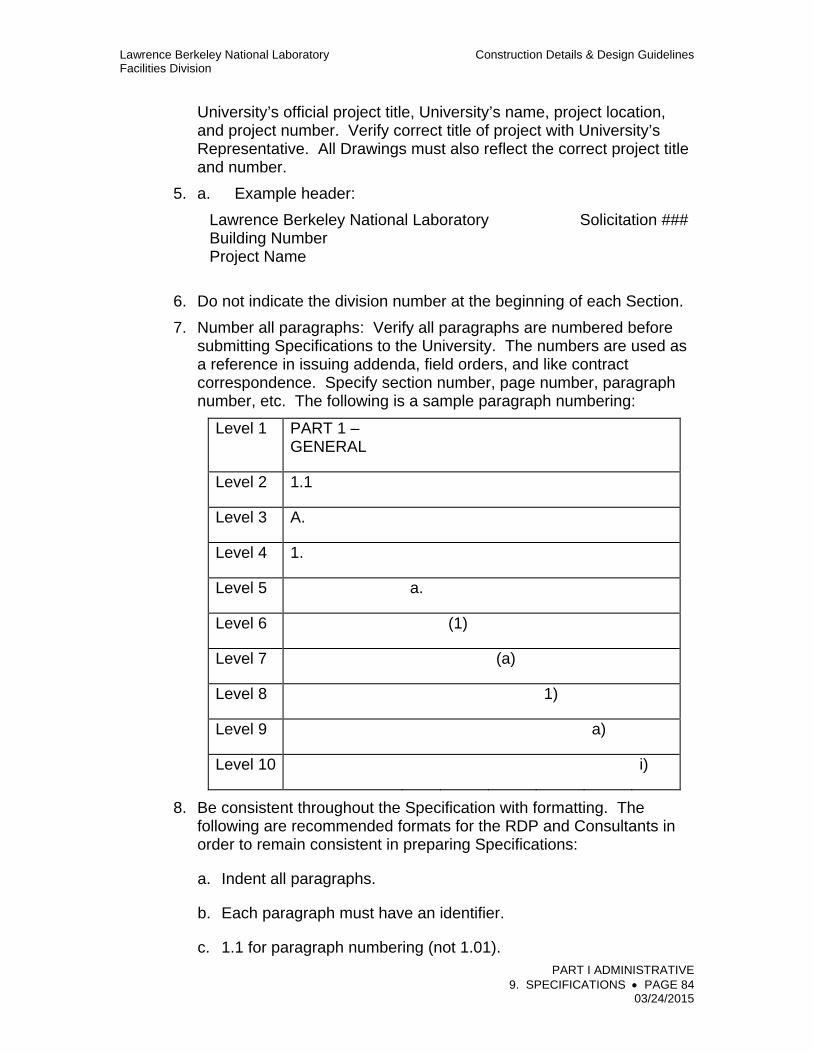
Lawrence Berkeley National Laboratory Construction Details & Design Guidelines Facilities Division
PART I ADMINISTRATIVE 9. SPECIFICATIONS PAGE 84 03/24/2015
University’s official project title, University’s name, project location, and project number. Verify correct title of project with University’s Representative. All Drawings must also reflect the correct project title and number.
5. a. Example header:
Lawrence Berkeley National Laboratory Solicitation ### Building Number Project Name
6. Do not indicate the division number at the beginning of each Section.
7. Number all paragraphs: Verify all paragraphs are numbered before submitting Specifications to the University. The numbers are used as a reference in issuing addenda, field orders, and like contract correspondence. Specify section number, page number, paragraph number, etc. The following is a sample paragraph numbering:
Level 1 PART 1 – GENERAL
Level 2 1.1
Level 3 A.
Level 4 1.
Level 5 a.
Level 6 (1)
Level 7 (a)
Level 8 1)
Level 9 a)
Level 10 i)
8. Be consistent throughout the Specification with formatting. The following are recommended formats for the RDP and Consultants in order to remain consistent in preparing Specifications:
a. Indent all paragraphs.
b. Each paragraph must have an identifier.
c. 1.1 for paragraph numbering (not 1.01).

Lawrence Berkeley National Laboratory Construction Details & Design Guidelines Facilities Division
PART I ADMINISTRATIVE 9. SPECIFICATIONS PAGE 85 03/24/2015
d. psi (not pounds per square inch).
e. three (3) (not 3 or three) for numbers.
f. The cautions and guidelines for abbreviations also apply to symbols substituted for words or terms. Two additional factors that limit the use of symbols are their conflict with use as command characters in software programs, and potential translation problems when converting from one software to another. Small symbols may also “bleed” together and become unreadable in a poorly printed text. Following are some of the symbols that should not be used in Specifications.
1) " for inch or inches
2) ' for foot or feet
3) % for percent
4) ° for degree
5) + for plus
6) - for minus
7) X for by, as in 2 X 4
8) / for per
9) @ for at
g. The use of parentheses and quotation marks should be minimized or avoided.
h. Contract Sum (not Contract Price, Construction Estimate, etc.).
i. Use “at no additional cost to the University” (not at no cost to the University).
j. Do not reference paragraph numbers within a section. When referencing other sections use the following example: Section 010000, General Requirements.
k. Do not use a colon after a paragraph title or subheading. For example, use MATERIALS not MATERIALS:

Lawrence Berkeley National Laboratory Construction Details & Design Guidelines Facilities Division
PART I ADMINISTRATIVE 9. SPECIFICATIONS PAGE 86 03/24/2015
9. Verify that all references to Division 01 are valid. RDP should cross check references of Section numbers and titles in the University’s Division 01.
10. Do not use the term “and/or” because it gives the Subcontractor the option to do one or the other. If the intent is to allow the Subcontractor an option, state “at Subcontractor’s option.”
11. Set the Word Processor options for automatic page breaks to avoid widows and orphans.
a. A widow is the last line of a paragraph that appears alone at the top of a page.
b. An orphan is the first line of a paragraph that appears alone at the bottom of a page.
c. Do not add manual page breaks or extra returns to move text to the next page. Instead, block and protect text to remain together.
12. Mark the end of each specification section as follows: END OF SECTION XXXXXX
13. Footers are required on all pages of Specification sections and consecutive numbering shall be placed at the bottom center of each page. Footers shall be printed in capital letters and reflect the section title, section number, and page number.
a. Example footer:
Resilient Flooring 096500-6 00/00/0000
14. Abbreviations
a. Industry Standards may be abbreviated after being written out, with abbreviation in parenthesis the first time used in each section. Abbreviations spelled out in General Provisions sections (Division 01 only) may be used in subsequent sections of that Division without being written out again. For example:
Aluminum Association (AA) Associated Air Balance Council (AABC) American Institute of Steel Construction (AISC) American Society for Testing and Materials (ASTM)
b. Do not abbreviate California Energy Commission (CEC refers to California Electrical Code).
CHECKLIST BEFORE SUBMITTING 100 PERCENT DOCUMENTS

Lawrence Berkeley National Laboratory Construction Details & Design Guidelines Facilities Division
PART I ADMINISTRATIVE 9. SPECIFICATIONS PAGE 87 03/24/2015
1. Are all sections contained in the Specifications?
2. Are all sections in the Specifications listed correctly?
3. Review for incomplete, unclear, or ambiguous statements. Some examples are:
a. Words missing from sentences.
b. Sentences or lines missing from paragraphs.
c. Meaningless or garbled statements.
d. Statements that conflict with other statements, or parts of the same statement that conflict with each other.
4. Check for incorrect content references. Some incorrect examples are:
a. Referencing paragraphs, sections, divisions that do not exist.
b. Referencing one document while information is actually in another.
c. Review for conflicting requirements and references.

Lawrence Berkeley National Laboratory Construction Details & Design Guidelines Facilities Division
PART I ADMINISTRATIVE 9. SPECIFICATIONS PAGE 88 03/24/2015
5. If related sections are used, verify all sections are contained in the specifications.
6. Review contents for clarity and completeness.
7. Check cross-references, including those to Drawings.
8. Check alternate and unit price references in Specifications and on Drawings. Review language of alternates for clarity and make sure they are clearly designated on the drawings.
9. Special license/experience or any other special requirement is identified.
10. Review phasing and sequencing requirements. Make sure they are clearly written and/or shown.
11. Review after printing for missing or out of order pages or sections.
12. Check that there are no widows/orphans:
a. Widow: last line of paragraph appears alone at the top of a page.
b. Orphan: first line of a paragraph appears alone at the bottom of a page.
13. Gender references have all been corrected.
14. No instructions have been given to anyone other than the Subcontractor.
15. 2nd manufacturers have been listed with “or equal”.
16. Ran spellchecker on file.
17. Checked for consistency throughout Specifications.
ADDENDA
In accordance with the UC Facilities Manual, only the office that issued the Bidding Documents may issue addenda by a method that provides proof of receipt to bidders and others who have taken out or received a set of Bidding Documents.
Requests for clarification or interpretation of the Bidding Documents shall be addressed only as follows:
Lawrence Berkeley National Laboratory Construction Details & Design Guidelines Facilities Division
PART I ADMINISTRATIVE 9. SPECIFICATIONS PAGE 89 03/24/2015
1. Bidding process inquiries shall be addressed to the correct University Procurement Administrator handling the Construction Subcontract.
2. Technical Project Inquiries shall be addressed to the person designated on the Project Directory in the Bidding Documents.
Addenda shall not be used to “clarify” items in Bidding Documents. The University’s Representative/RDP shall discuss the request for clarification with the individual making the request. The University’s Representative then determines if the question is valid (e.g., requiring changes, additions, deletions in the Bidding Documents) and if so, how it is to be addressed in an addendum. There are no provisions in the addendum form that allow for “clarifications.”
The RDP shall address any modifications to the Technical Specifications during the bidding period. The RDP is responsible for receiving, incorporating, and coordinating any or all addenda items received from the consultant(s). Do not instruct the consultant(s) to directly send their addenda items to the Procurement staff. It is the responsibility of the RDP to review and approve the correction(s) and/or change(s) of its consultant(s) prior to submitting addenda to the University. The RDP should incorporate all addenda items received from their consultants into a single addendum document prior to submitting this document to the University. Copies of questions and log should be emailed daily to the University’s Representative. The University’s Representative shall coordinate any information required for the addenda between the RDP and Contracts staff.
If an item in the Bidding Documents is unclear or does not make sense, the following may be done by addendum:
1. Addition: add language to the item(s) in question.
2. Deletion: delete language from the item(s) in question.
3. Change: change the item(s) in question.
The addendum shall be prepared as follows:
1. Corrections and changes to the Bidding Documents shall be made in the form of a written addendum issued by Procurement Administrator only. Changes made in any other manner are not legally binding and the Bidding Documents state that Bidders shall not rely upon them.
2. The University’s Representative and Procurement Administrator set the deadline for receiving all questions of the Bidding Documents. Questions received after the deadline may be answered at the discretion of the University’s Representative.

Lawrence Berkeley National Laboratory Construction Details & Design Guidelines Facilities Division
PART I ADMINISTRATIVE 9. SPECIFICATIONS PAGE 90 03/24/2015
3. The addendum must be issued such that it is received by bidders no later than three (3) full working days before the bid deadline. If the addendum cannot be received by bidders within the three (3) full working days time frame, the bid date must be extended.
4. Procurement staff shall issue a schedule to the RDP outlining the time that the final addendum must be received in order to not extend the bid date.
5. The RDP and Consultants are not to issue any verbal statements regarding the Bidding Documents.
6. Changes shall be submitted to the University as follows:
a. Drawings: One (1) set of wet stamped reproducible originals, an agreed upon number of sets of prints, and a computer disk version, formatted in AutoCAD “.DWG” file format.
b. Specifications: One (1) original wet stamped hardcopy and a CD, formatted in Microsoft Word 2010 or later format. Font: Times New Roman, 11 point.
7. Formatting of the addendum shall be discussed at the Specifications review meeting held in early Construction Documents phase.
QUALITY ASSURANCE
1. Checking of Documents
a. The RDP shall ensure that the work is adequately checked in an orderly and consistent manner for constructability of the design; accessibility, maintainability, serviceability, and sustainability of equipment; completeness; technical accuracy; and coordination between the disciplines and between plans and specifications. A procedure equivalent to the procedure outlined in "Checking of Architecture and Engineering Documents," RD3.8 of the CDDG, Volume 4 – RDs, shall be used.
b. A copy of the quality control marked-up set shall be included as part of the Final Design 100% submittal. The cover letter shall include a certification that the RDP performed a detailed review and coordination of the documents. The check set shall be returned to the RDP after review by the University.
2. Calculations
a. All final design calculations shall be checked, stamped, and signed by an engineer licensed in California in addition to the engineer

Lawrence Berkeley National Laboratory Construction Details & Design Guidelines Facilities Division
PART I ADMINISTRATIVE 9. SPECIFICATIONS PAGE 91 03/24/2015
who performed the calculations.
3. Signatures
a. The final construction drawings, specifications, calculations, and engineering reports shall contain the stamp, signature, and license number of the appropriate California licensed architect, engineer, or engineers.