1 Gantry modules pneumatic PMP - Afag · Gantry modules pneumatic PMP & PMP-c Page ... A Mounting...
12
135 afag.com afag.com 136 Handling technology HT Components linear Handling technology HT Components linear Gantry modules pneumatic PMP PMP & PMP-c Table of contents: PMP & PMP-c Gantry modules pneumatic PMP & PMP-c Page PMP 138 PMP-c 146 Accessories PMP & PMP-c 153 1 2 3 4 6 7 8 9 10 11 12 13 14 15 16 17 18 19 20 21 22 23 24 25 26 27 28 29 30 31 32 33 34 35 36 37 38 1 2 3 4 5 6 7 8 9 10 11 12 13 14 15 16 17 18 19 20 21 22 23 24 25 26 27 28 29 30 31 32 33 34 35 36 37 38
Transcript of 1 Gantry modules pneumatic PMP - Afag · Gantry modules pneumatic PMP & PMP-c Page ... A Mounting...
135 afag.com afag.com 136Handling technology HT Components linearHandling technology HT Components linear
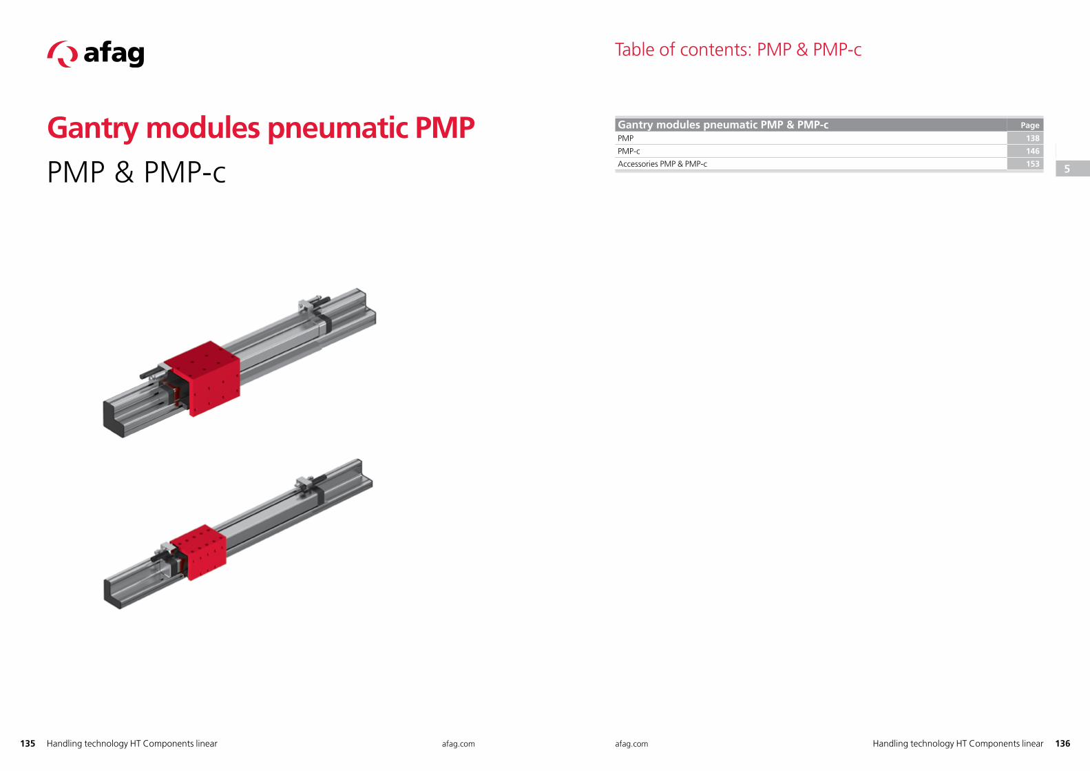
Gantry modules pneumatic PMPPMP & PMP-c
Table of contents: PMP & PMP-c
Gantry modules pneumatic PMP & PMP-c Page
PMP 138
PMP-c 146
Accessories PMP & PMP-c 153
123
45
6
78
91011
1213
14
151617
18
1920212223
24
2526
272829303132
33
34
35
36
37
38
123
4
5
6
78
91011
1213
14
151617
18
1920212223
24
2526
272829303132
33
34
35
36
37
38
137 afag.com afag.com 138Handling technology HT Components linearHandling technology HT Components linear
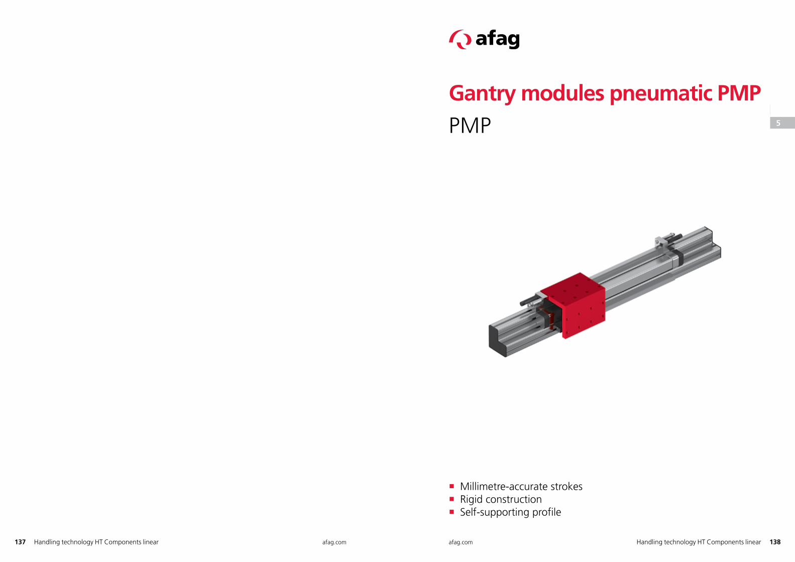
Gantry modules pneumatic PMPPMP
� Millimetre-accurate strokes � Rigid construction � Self-supporting profile
123
45
6
78
91011
1213
14
151617
18
1920212223
24
2526
272829303132
33
34
35
36
37
38
123
4
5
6
78
91011
1213
14
151617
18
1920212223
24
2526
272829303132
33
34
35
36
37
38
139 afag.com afag.com 140Handling technology HT Components linearHandling technology HT Components linear
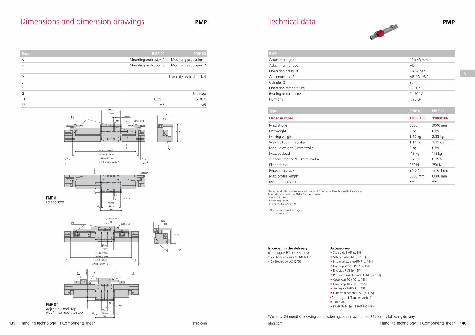
Dimensions and dimension drawings PMP
Type PMP 01 PMP 02
A Mounting protrusion 1 Mounting protrusion 1
B Mounting protrusion 2 Mounting protrusion 2
C
D Proximity switch bracket
E
F
G End stop
P1 G1/8 “ G1/8 “
P2 M5 M5
P1
P2
PMP 01Feste Endanschläge
SD M14x1-1P1
P2
C D E G
F
PMP 02Verstellbare Endanschlägeplus 1 Zwischenanschlag
Technical data PMP
PMP
Attachment grid 48 x 48 mm
Attachment thread M6
Operating pressure 6 +/-2 bar
Air connection P M5 / G 1/8 “
Cylinder Ø 25 mm
Operating temperature 0 - 50 °C
Bearing temperature 0 - 50 °C
Humidity < 90 %
Type PMP 01 PMP 02
Order number 11000105 11000106
Max. stroke 3000 mm 3000 mm
Net weight 6 kg 6 kg
Moving weight 1.87 kg 2.33 kg
Weight/100 mm stroke 1.11 kg 1.11 kg
Module weight, 0 mm stroke 6 kg 6 kg
Max. payload *15 kg *15 kg
Air consumption/100 mm stroke 0.25 NL 0.25 NL
Piston force 250 N 250 N
Repeat accuracy +/- 0.1 mm +/- 0.1 mm
Max. profile length 6000 mm 6000 mm
Mounting position
The technical data refer to a nominalpressure of 6 bar under Afag standard testconditions.Note: Also included in the PMP 02 scope of delivery: 1 x stop slide PMP 2 x end stops PMP 1 x intermediate stop PMP
* Observe operation time diagram** 0 mm stroke
Fix end stop
Adjustable end stopplus 1 intermediate stop
Inlcuded in the delivery (Catalogue HT accessories)
� 2x Shock absorber SD M14x1 -1
� 2x Stop screw AS 12/60
Accessories � Stop slide PMP [p. 153]
� Safety brake PMP [p. 153]
� Intermediate stop PMP [p. 154]
� Fine adjustment PMP [p. 154]
� End stop PMP [p. 154]
� Proximity switch bracket PMP [p. 154]
� Cover cap 40 x 40 [p. 155]
� Cover cap 40 x 80 [p. 155]
� Angle profile PMP [p. 155]
� Lubricator adapter PMP [p. 155]
(Catalogue HT accessories) � T-nut M8
� INI d6.5x44-Sn1.5-PNP-NO-M8x1
Warranty: 24 months following commissioning, but a maximum of 27 months following delivery
123
45
6
78
91011
1213
14
151617
18
1920212223
24
2526
272829303132
33
34
35
36
37
38
123
4
5
6
78
91011
1213
14
151617
18
1920212223
24
2526
272829303132
33
34
35
36
37
38
141 afag.com afag.com 142Handling technology HT Components linearHandling technology HT Components linear
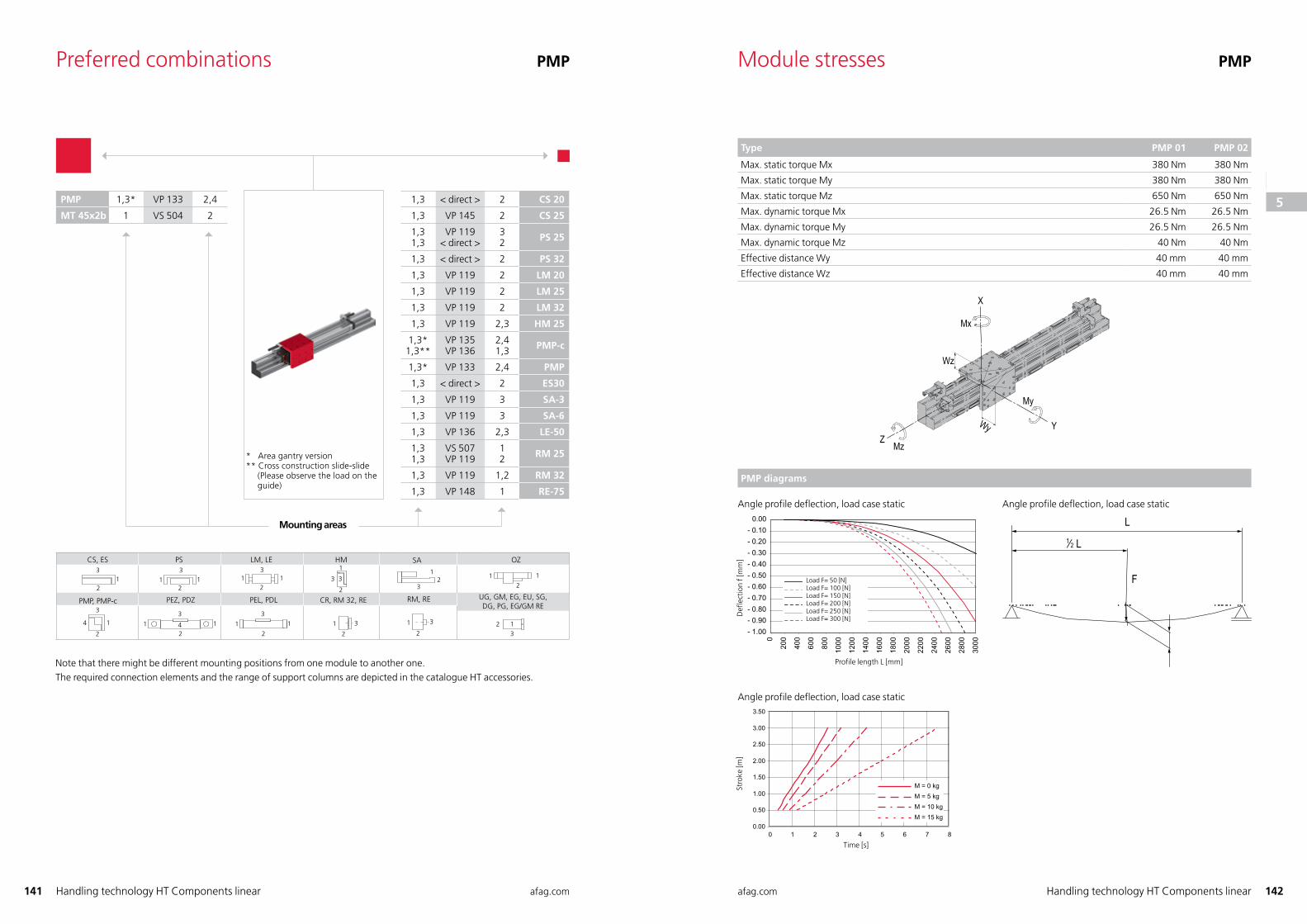
Preferred combinations PMP
* Area gantry version** Cross construction slide-slide (Please observe the load on the guide)
1,3 < direct > 2 CS 20
1,3 VP 145 2 CS 25
1,31,3
VP 119< direct >
32 PS 25
1,3 < direct > 2 PS 32
1,3 VP 119 2 LM 20
1,3 VP 119 2 LM 25
1,3 VP 119 2 LM 32
1,3 VP 119 2,3 HM 25
1,3*1,3**
VP 135VP 136
2,41,3 PMP-c
1,3* VP 133 2,4 PMP
1,3 < direct > 2 ES30
1,3 VP 119 3 SA-3
1,3 VP 119 3 SA-6
1,3 VP 136 2,3 LE-50
1,31,3
VS 507VP 119
12 RM 25
1,3 VP 119 1,2 RM 32
1,3 VP 148 1 RE-75
2
1
3 3
1232
1 3
2
3
42
1
21
3
3
21 1
12
3
31
21
1
3
2
4
2
31 1
1 1 1 1
HM
UG, GM, EG, EU, SG,DG, PG, EG/GM RE
CR, RM 32, RE
LM, LECS, ES PS
PMP, PMP-c
SA
RM, RE
OZ
PEZ, PDZ
2
3
PEL, PDL
Mounting areas
PMP 1,3* VP 133 2,4
MT 45x2b 1 VS 504 2
Note that there might be different mounting positions from one module to another one.The required connection elements and the range of support columns are depicted in the catalogue HT accessories.
Module stresses PMP
Type PMP 01 PMP 02
Max. static torque Mx 380 Nm 380 Nm
Max. static torque My 380 Nm 380 Nm
Max. static torque Mz 650 Nm 650 Nm
Max. dynamic torque Mx 26.5 Nm 26.5 Nm
Max. dynamic torque My 26.5 Nm 26.5 Nm
Max. dynamic torque Mz 40 Nm 40 Nm
Effective distance Wy 40 mm 40 mm
Effective distance Wz 40 mm 40 mm
X
ZYWy
Wz
Mx
My
Mz
PMP diagrams
Angle profile deflection, load case static
BelastungBelastungBelastungBelastungBelastungBelastung
Angle profile deflection, load case static
F
L1⁄2 L
Angle profile deflection, load case static
Profile length L [mm]
Def
lect
ion
f [m
m]
Load F= 50 [N] Load F= 100 [N]Load F= 150 [N]Load F= 200 [N]Load F= 250 [N]Load F= 300 [N]
Time [s]
Stro
ke [m
]
123
45
6
78
91011
1213
14
151617
18
1920212223
24
2526
272829303132
33
34
35
36
37
38
123
4
5
6
78
91011
1213
14
151617
18
1920212223
24
2526
272829303132
33
34
35
36
37
38
143 afag.com afag.com 144Handling technology HT Components linear Handling technology HT Components linear
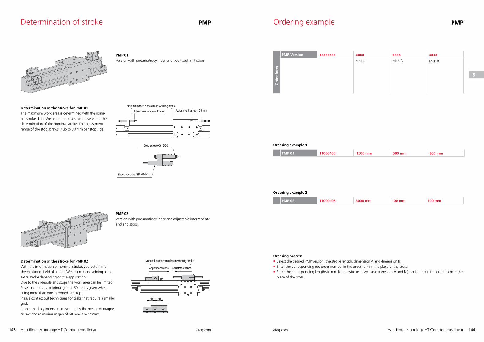
Determination of stroke PMP
PMP 01Version with pneumatic cylinder and two fi xed limit stops.
Determination of the stroke for PMP 01The maximum work area is determined with the nomi-nal stroke data. We recommend a stroke reserve for the determination of the nominal stroke. The adjustment range of the stop screws is up to 30 mm per stop side.
Determination of the stroke for PMP 02With the information of nominal stroke, you determinethe maximum fi eld of action. We recommend adding someextra stroke depending on the application.Due to the slideable end stops the work area can be limited.Please note that a minimal grid of 50 mm is given when using more than one intermediate stop. Please contact out technicians for tasks that require a smaller grid. If pneumatic cylinders are measured by the means of magne-tic switches a minimum gap of 60 mm is necessary.
PMP 02Version with pneumatic cylinder and adjustable intermediate and end stops.
Nennhub = maximaler Arbeitshub
Verstellbereich Verstellbereich
Nennhub = maximaler ArbeitshubVerstellbereich = 30 mm Verstellbereich = 30 mm
Anschlagschraube AS 12/60
Stoßdämpfer SD M14x1-1
Nominal stroke = maximum working strokeAdjustment range = 30 mm Adjustment range = 30 mm
Stop screw AS 12/60
Shock absorber SD M14x1-1
Adjustment range Adjustment range
Nominal stroke = maximum working stroke
Ordering example PMP
Ord
er f
orm
PMP-Version xxxxxxxx xxxx xxxx xxxx
stroke Maß A Maß B
Ordering example 1
PMP 01 11000105 1500 mm 500 mm 800 mm
Ordering example 2
PMP 02 11000106 3000 mm 100 mm 100 mm
Ordering process � Select the desired PMP version, the stroke length, dimension A and dimension B. � Enter the corresponding red order number in the order form in the place of the cross. � Enter the corresponding lengths in mm for the stroke as well as dimensions A and B (also in mm) in the order form in the place of the cross.
123
45
6
78
91011
1213
14
151617
18
1920212223
24
2526
272829303132
33
34
35
36
37
38
123
4
5
6
78
91011
1213
14
151617
18
1920212223
24
2526
272829303132
33
34
35
36
37
38
145 afag.com afag.com 146Handling technology HT Components linearHandling technology HT Components linear
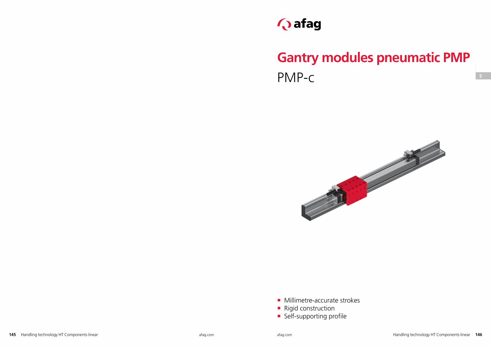
Gantry modules pneumatic PMPPMP-c
� Millimetre-accurate strokes � Rigid construction � Self-supporting profile
123
45
6
78
91011
1213
14
151617
18
1920212223
24
2526
272829303132
33
34
35
36
37
38
123
4
5
6
78
91011
1213
14
151617
18
1920212223
24
2526
272829303132
33
34
35
36
37
38
147 afag.com afag.com 148Handling technology HT Components linearHandling technology HT Components linear
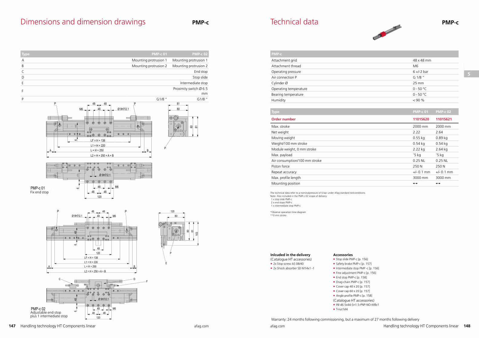
Technical data PMP-c
PMP-c
Attachment grid 48 x 48 mm
Attachment thread M6
Operating pressure 6 +/-2 bar
Air connection P G 1/8 “
Cylinder Ø 25 mm
Operating temperature 0 - 50 °C
Bearing temperature 0 - 50 °C
Humidity < 90 %
Type PMP-c 01 PMP-c 02
Order number 11015620 11015621
Max. stroke 2000 mm 2000 mm
Net weight 2.22 2.64
Moving weight 0.55 kg 0.89 kg
Weight/100 mm stroke 0.54 kg 0.54 kg
Module weight, 0 mm stroke 2.22 kg 2.64 kg
Max. payload *5 kg *5 kg
Air consumption/100 mm stroke 0.25 NL 0.25 NL
Piston force 250 N 250 N
Repeat accuracy +/- 0.1 mm +/- 0.1 mm
Max. profile length 3000 mm 3000 mm
Mounting position
The technical data refer to a nominalpressure of 6 bar under Afag standard testconditions.Note: Also included in the PMP-c 02 scope of delivery: 1 x stop slide PMP-c 2 x end stops PMP-c 1 x intermediate stop PMP-c
* Observe operation time diagram** 0 mm stroke
Dimensions and dimension drawings PMP-c
Type PMP-c 01 PMP-c 02
A Mounting protrusion 1 Mounting protrusion 1
B Mounting protrusion 2 Mounting protrusion 2
C End stop
D Stop slide
E Intermediate stop
F Proximity switch Ø 6.5
mm
P G1/8 “ G1/8 “
48 4848
48
4848 48
M6
M6
4848
66
120
120
12080
80 8110
3
Ø 9H7/2.1
Ø 9H7/2.1
P P
A B
C D
P
E
LF = H + 138L1 = H + 220L = H + 250L2 = H + 250 + A + B
PMP-c 02
F
48 4848 Ø 9H7/2.1M6
P 8180
P
P
6 LF = H + 138L1 = H + 220L = H + 250L2 = H + 250 + A + B
A B
6
Ø 9H7/2.1
4848 48
120
M6
8180PMP-c 01Feste Endanschläge
Verstellbare Endanschlägeplus 1 Zwischenanschlag
Fix end stop
Adjustable end stopplus 1 intermediate stop
Inlcuded in the delivery (Catalogue HT accessories)
� 2x Stop screw AS 08/40
� 2x Shock absorber SD M14x1 -1
Accessories � Stop slide PMP-c [p. 156]
� Safety brake PMP-c [p. 157]
� Intermediate stop PMP -c [p. 156]
� Fine adjustment PMP-c [p. 156]
� End stop PMP-c [p. 158]
� Drag-chain PMP-c [p. 157]
� Cover cap 40 x 20 [p. 157]
� Cover cap 60 x 20 [p. 157]
� Angle profile PMP-c [p. 158]
(Catalogue HT accessories) � INI d6.5x44-Sn1.5-PNP-NO-M8x1
� T-nut M4
Warranty: 24 months following commissioning, but a maximum of 27 months following delivery
123
45
6
78
91011
1213
14
151617
18
1920212223
24
2526
272829303132
33
34
35
36
37
38
123
4
5
6
78
91011
1213
14
151617
18
1920212223
24
2526
272829303132
33
34
35
36
37
38
149 afag.com afag.com 150Handling technology HT Components linearHandling technology HT Components linear
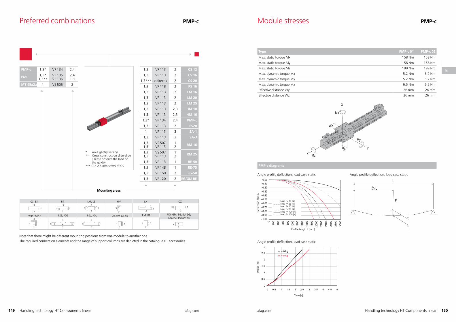
Module stresses PMP-c
Type PMP-c 01 PMP-c 02
Max. static torque Mx 158 Nm 158 Nm
Max. static torque My 158 Nm 158 Nm
Max. static torque Mz 199 Nm 199 Nm
Max. dynamic torque Mx 5.2 Nm 5.2 Nm
Max. dynamic torque My 5.2 Nm 5.2 Nm
Max. dynamic torque Mz 6.5 Nm 6.5 Nm
Effective distance Wy 26 mm 26 mm
Effective distance Wz 26 mm 26 mm
X
ZYWy
Wz
Mx
My
Mz
PMP-c diagrams
Angle profile deflection, load case static
BelastungBelastungBelastungBelastungBelastungBelastung
Angle profile deflection, load case static
F
L1⁄2 L
Angle profile deflection, load case static
Preferred combinations PMP-c
1,3 VP 113 2 CS 12
1,3 VP 113 2 CS 16
1,3*** < direct > 2 CS 20
1,3 VP 118 2 PS 16
1,3 VP 113 2 LM 16
1,3 VP 113 2 LM 20
1,3 VP 113 2 LM 25
1,3 VP 113 2,3 HM 10
1,3 VP 113 2,3 HM 16
1,3* VP 134 2,4 PMP-c
1,3 VP 113 2 ES20
1 VP 113 3 SA-1
1,3 VP 113 3 SA-3
1,31,3
VS 507VP 113
12 RM 16
1,31,3
VS 507VP 113
12 RM 25
1,3 VP 113 1 RE-50
1,3 VP 148 1 RE-75
1,3 VP 150 2 SG-50
1,3 VP 120 2 EG/GM RE
2
1
3 3
1232
1 3
2
3
42
1
21
3
3
21 1
12
3
31
21
1
3
2
4
2
31 1
1 1 1 1
HM
UG, GM, EG, EU, SG,DG, PG, EG/GM RE
CR, RM 32, RE
LM, LECS, ES PS
PMP, PMP-c
SA
RM, RE
OZ
PEZ, PDZ
2
3
PEL, PDL
Mounting areas
PMP-c 1,3* VP 134 2,4
PMP 1,3*1,3**
VP 135VP 136
2,41,3
MT 45x2a 1 VS 505 2
Note that there might be different mounting positions from one module to another one.The required connection elements and the range of support columns are depicted in the catalogue HT accessories.
* Area gantry version** Cross construction slide-slide (Please observe the load on the guide)*** Cut 2.5 mm srews of CS
Profile length L [mm]
Def
lect
ion
f [m
m]
Load F= 10 [N] Load F= 25 [N]Load F= 50 [N]Load F= 75 [N]Load F= 100 [N]Load F= 150 [N]
Time [s]
Stro
ke [m
]
123
45
6
78
91011
1213
14
151617
18
1920212223
24
2526
272829303132
33
34
35
36
37
38
123
4
5
6
78
91011
1213
14
151617
18
1920212223
24
2526
272829303132
33
34
35
36
37
38
151 afag.com afag.com 152Handling technology HT Components linearHandling technology HT Components linear
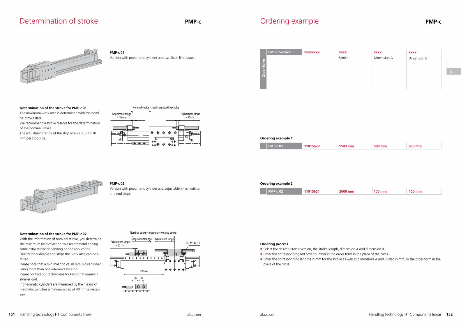
Determination of stroke PMP-c
PMP-c 01Version with pneumatic cylinder and two fi xed limit stops.
Determination of the stroke for PMP-c 01The maximum work area is determined with the nomi-nal stroke data. We recommend a stroke reserve for the determination of the nominal stroke. The adjustment range of the stop screws is up to 10 mm per stop side.
Determination of the stroke for PMP-c 02With the information of nominal stroke, you determinethe maximum fi eld of action. We recommend adding some extra stroke depending on the application.Due to the slideable end stops the work area can be li-mited.Please note that a minimal grid of 30 mm is given when using more than one intermediate stop. Please contact out technicians for tasks that require a smaller grid. If pneumatic cylinders are measured by the means of magnetic switches a minimum gap of 40 mm is neces-sary.
PMP-c 02Version with pneumatic cylinder and adjustable intermediate and end stops.
Verstellbereich = 10 mm
Nennhub = Maximalhub
Verstellbereich = 10 mm
Verstellbereich= 20 mm
Nennhub = maximaler Arbeitshub
Verstellbereich VerstellbereichSD M14x1-1
Hub
36 30
Nominal stroke = maximum working stroke
Adjustment range = 10 mm
Adjustment range = 10 mm
Adjustment range = 20 mm
Adjustment range Adjustment range
Nominal stroke = maximum working stroke
Stroke
Ordering example PMP-c
Ord
er f
orm
PMP-c Version xxxxxxxx xxxx xxxx xxxx
Stroke Dimension A Dimension B
Ordering example 1
PMP-c 01 11015620 1500 mm 500 mm 800 mm
Ordering example 2
PMP-c 02 11015621 2000 mm 100 mm 100 mm
Ordering process � Select the desired PMP-c version, the stroke length, dimension A and dimension B. � Enter the corresponding red order number in the order form in the place of the cross. � Enter the corresponding lengths in mm for the stroke as well as dimensions A and B (also in mm) in the order form in the place of the cross.
123
45
6
78
91011
1213
14
151617
18
1920212223
24
2526
272829303132
33
34
35
36
37
38
123
4
5
6
78
91011
1213
14
151617
18
1920212223
24
2526
272829303132
33
34
35
36
37
38
153 afag.com afag.com 154Handling technology HT Components linearHandling technology HT Components linear
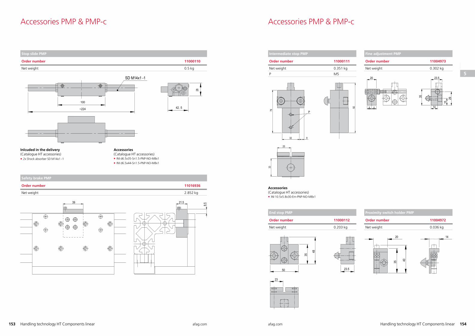
Stop slide PMP
Order number 11000110
Net weight 0.5 kg
Safety brake PMP
Order number 11016936
Net weight 2.852 kg
39 21.58.5
Intermediate stop PMP
Order number 11000111
Net weight 0.351 kg
P M5
P
Fine adjustment PMP
Order number 11004973
Net weight 0.302 kg
20 23.5
35
14
1529
= =
End stop PMP
Order number 11000112
Net weight 0.203 kg
23
50
35
48
23.5
Proximity switch holder PMP
Order number 11004972
Net weight 0.036 kg
20
35 40
14
Accessories PMP & PMP-c Accessories PMP & PMP-c
Inlcuded in the delivery (Catalogue HT accessories)
� 2x Shock absorber SD M14x1 -1
Accessories(Catalogue HT accessories)
� INI d6.5x35-Sn1.5-PNP-NO-M8x1
� INI d6.5x44-Sn1.5-PNP-NO-M8x1
Accessories(Catalogue HT accessories)
� INI 10.5x5.8x30-Em-PNP-NO-M8x1
123
45
6
78
91011
1213
14
151617
18
1920212223
24
2526
272829303132
33
34
35
36
37
38
123
4
5
6
78
91011
1213
14
151617
18
1920212223
24
2526
272829303132
33
34
35
36
37
38
155 afag.com afag.com 156Handling technology HT Components linearHandling technology HT Components linear
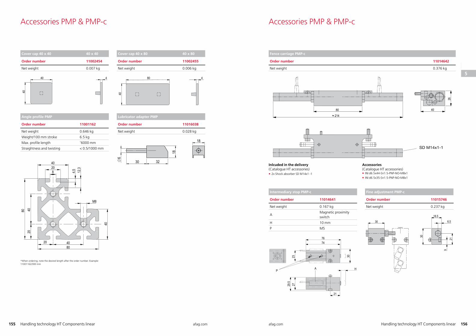
Cover cap 40 x 40 40 x 40
Order number 11002454
Net weight 0.007 kg
40 4
40
Cover cap 40 x 80 40 x 80
Order number 11002455
Net weight 0.006 kg
80
40
4
Angle profile PMP
Order number 11001162
Net weight 0.646 kg
Weight/100 mm stroke 6.5 kg
Max. profile length *6000 mm
Straightness and twisting < 0.5/1000 mm
40208 4.5 12
.3
M8
40
4080
20
204080
* When ordering, note the desired length after the order number. Example: 11001162/300 mm
Lubricator adapter PMP
Order number 11016038
Net weight 0.028 kg
Fence carriage PMP-c
Order number 11014642
Net weight 0.376 kg
80
≈ 214
40
26
Intermediary stop PMP-c
Order number 11014641
Net weight 0.167 kg
AMagnetic proximity switch
H 10 mm
P M5
30
H
21
7674
232729
.5
P A
Fine adjustment PMP-c
Order number 11015746
Net weight 0.237 kg
30
18.5
6.5
21
9
30
Accessories PMP & PMP-c Accessories PMP & PMP-c
Inlcuded in the delivery (Catalogue HT accessories)
� 2x Shock absorber SD M14x1 -1
Accessories(Catalogue HT accessories)
� INI d6.5x44-Sn1.5-PNP-NO-M8x1
� INI d6.5x35-Sn1.5-PNP-NO-M8x1
123
45
6
78
91011
1213
14
151617
18
1920212223
24
2526
272829303132
33
34
35
36
37
38
123
4
5
6
78
91011
1213
14
151617
18
1920212223
24
2526
272829303132
33
34
35
36
37
38
157 afag.com afag.com 158Handling technology HT Components linearHandling technology HT Components linear
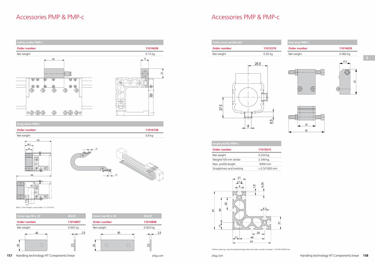
Safety brake PMP-c
Order number 11014638
Net weight 0.15 kg
43 17
21
Drag-chain PMP-c
Order number 11014738
Net weight 0.8 kg
125
38.2
30
165
11
11
Note: Chain length = axis stroke: 2 + 210 mm
Cover cap 40 x 20 40x20
Order number 11014897
Net weight 0.002 kg
20
40 2.5
Cover cap 60 x 20 60x20
Order number 11014898
Net weight 0.003 kg
60 2.5
20
T-slot cover profile NA
Order number 11012219
Net weight 0.02 kg
25.5
27.5
6.5
8
End stop PMP-c
Order number 11014639
Net weight 0.082 kg
17.5
42
30
60
Angle profile PMP-c
Order number 11015615
Net weight 0.254 kg
Weight/100 mm stroke 2.544 kg
Max. profile length *3000 mm
Straightness and twisting < 0.5/1000 mm
* When ordering, note the desired length after the order number. Example: 11015615/300 mm
Accessories PMP & PMP-c Accessories PMP & PMP-c
123
45
6
78
91011
1213
14
151617
18
1920212223
24
2526
272829303132
33
34
35
36
37
38
123
4
5
6
78
91011
1213
14
151617
18
1920212223
24
2526
272829303132
33
34
35
36
37
38