1 FOREWORD - SupraManiakai.supramania.com/Supra/A70 Chassis Collision Repair Manual.pdf ·...
79
Manual Name Pub. No. 7M−GE Engine Repair Manual TOYOTA SUPRA Chassis and Body Repair Manual TOYOTA SUPRA Chassis and Body Repair Manual Supplement TOYOTA SUPRA Electrical Wiring Diagram Manual TOYOTA SUPRA Repair Manual (USA and Canada) TOYOTA SUPRA Electrical Wiring Diagram Manual (USA and Canada) Fundamental Body Repair Procedures Fundamental Painting Procedures BRM002E 36438E M/Y Version M/Y Version EWD013E RM036E RM029E RM027E FOREWORD This repair manual has been prepared to provide information on the repair methods (including cutting and welding operations, but excluding painting) recommended by TOYOTA for collision− damaged body components of the TOYOTA SUPRA. Applicable models: MA70 series This manual consists of body repair methods, exploded dia- grams and illustrations of the body components and other infor- mation relating to body panel replacement such as handling pre- cautions, tools, equipment, etc. However, it should be noted that the front fenders of all TOYOTA models are bolted on and re- quire no welding. Body construction will sometimes differ depending on specifica- tions and country of destination. Therefore, please keep in mind that the information contained herein is based on vehicles for general destinations. For the service of specifications and repair procedures other than collision−damaged body components of the TOYOTA SUPRA, refer to the following repair manuals. All information contained in this manual is the most up−to−date at the time of publication. However, specifications and proce- dures are subject to change without prior notice. TOYOTA MOTOR CORPORATION 1
-
Upload
duongquynh -
Category
Documents
-
view
232 -
download
0
Transcript of 1 FOREWORD - SupraManiakai.supramania.com/Supra/A70 Chassis Collision Repair Manual.pdf ·...

Manual Name Pub. No.7M−GE Engine Repair Manual
TOYOTA SUPRA Chassis and BodyRepair Manual
TOYOTA SUPRA Chassis and BodyRepair Manual Supplement
TOYOTA SUPRA Electrical WiringDiagram Manual
TOYOTA SUPRA Repair Manual(USA and Canada)
TOYOTA SUPRA Electrical WiringDiagram Manual (USA and Canada)
Fundamental Body Repair Procedures
Fundamental Painting Procedures
BRM002E
36438E
M/Y Version
M/Y Version
EWD013E
RM036E
RM029E
RM027E
FOREWORD
This repair manual has been prepared to provide information onthe repair methods (including cutting and welding operations,but excluding painting) recommended by TOYOTA for collision−damaged body components of the TOYOTA SUPRA.
Applicable models: MA70 series
This manual consists of body repair methods, exploded dia-grams and illustrations of the body components and other infor-mation relating to body panel replacement such as handling pre-cautions, tools, equipment, etc. However, it should be noted thatthe front fenders of all TOYOTA models are bolted on and re-quire no welding.
Body construction will sometimes differ depending on specifica-tions and country of destination. Therefore, please keep in mindthat the information contained herein is based on vehicles forgeneral destinations.
For the service of specifications and repair procedures otherthan collision−damaged body components of the TOYOTASUPRA, refer to the following repair manuals.
All information contained in this manual is the most up−to−dateat the time of publication. However, specifications and proce-dures are subject to change without prior notice.
TOYOTA MOTOR CORPORATION
1
mm in.87 3.15
200 7.87
QUARTER PANEL
Cut and Join Location
HOW TO USE THIS MANUALEach repair method description provided in Section RE of this manual comprises two pages, divided into2 blocks (REMOVAL AND INSTALLATION) and includes illustrations to facilitate body repair.
RE−26 BODY PANEL REPLACEMENT−Rear Body Components
QUARTER PANEL (CUT)
REMOVAL
Cut and Join Location200 mm
80 mm
[Cut and Join Location]
Front
Braze
Rear
1. Cut and join the quarter panel as shown above.
REPLACEMENT PART AND METHOD
(CUT)Replacement method
(ASSY) Assembly replacement. . . . . (CUT) Major cutting (less than 1/2 of part used). . . . . . (CUT−H) Half cutting (about 1/2 of part used). . . . (CUT−P) Partial cutting (most of part used). . . .
Replacement part
BODY VARIATIONS AND PART LOCATIONBody variations: Non All models. . . .
REMOVAL DIAGRAMDescribes in detail removal of the damaged part involving repair by cutting.
REMOVAL GUIDEProvides additional information to more efficiently help you perform the removal.
INTRODUCTIONIN-2

mm in.5 0.20
1. Before temporarily installing the new part, applybody sealer to the wheel arch portion.
NOTE:1) Apply sealer approx. 5 mm (0.20 in.) from the
flange, avoiding any oozing.
2) Apply evenly, approx. 3 − 4 mm (0.12 − 0.16 in.)in diameter.
3) For other sealing points, refer to section SU.
BODY PANEL REPLACEMENT−Rear Body Components RE−27
INSTALLATION
Butt Weld
Butt Weld
Body Sealer
Braze
Body Sealer
About 5 mm
2. Temporarily installing the new part and check the fit ofthe front door, luggage compartment door and rearcombination lamp.
INSTALLATION DIAGRAMDescribes in detail installation of the new part involving repair by welding and/or cutting, but exclud-ing painting.
INSTALLATION GUIDEProvides additional information to more efficiently help you perform the installation.
SYMBOLSSee page IN−4.
ILLUSTRATION OF WELD POINTWeld method and panel position symbols.See page IN−5.
INTRODUCTION IN-3

SYMBOLS MEANING ILLUSTRATION
SAW CUT ORROUGH CUT
REMOVE BRAZE
(See page IN−5)
SPOT WELD ORMIG PLUG WELD
WELD POINTS
BRAZE
CONTINUOUS MIGWELD (BUTT WELDOR TACK WELD)
BODY SEALER
SYMBOLSThe following symbols are used in the welding Diagrams in Section RE of this manual to indicate cuttingareas and the types of weld required.
INTRODUCTIONIN-4
Remove weld point and panel position
Weld points
REMOVAL
Weld method and panel position
Weld points
INSTALLATION
SYMBOL MEANING ILLUSTRATION SYMBOL
Spot Weld
MEANING ILLUSTRATION
RemoveWeldPoints
(Outside)
Mig PlugWeld
(Middle)
(Inside)
Spot MIGWeld
HINT: Panel position syrnbols are as seen from theworking posture.
Illustration of Weld Point Symbols
EXAMPLE:
INTRODUCTION IN-5

GENERAL REPAIR INSTRUCTIONSWork Precautions
SAFETY1. Before performing repair work, check
for fuel leaks. If a leak is found, be sureto close the opening totally.
2. If it is necessary to use a frame in thearea of the fuel tank, first remove thetank and plug the fuel line.
SAFETYNever stand in directline with the chain whenusing a puller an thebody or frame, and besure to attach a safetycable.
VEHICLE PROTECTIONWhen welding, protect thepainted surfaces, windows,seats and carpet with heat−resistant, fire−proof covers.
WRONG
Glass Cover
Safety Cable
Seat Cover
WRONG
SAFETYBefore performing repair work,disconnect the battery cables.
SAFETY WORK CLOTHES
In addition to the usual mechanic wear, cap and Safety shoes,the necessary gloves, head protector, glasses, ear plugs, faceprotector, dust−prevention mask, etc. should be worn as thesituation demands.
Welder’sGlasses Body
MechanicStand
Dust−PreventionMask
FaceProtector
EarPlugs
HeadProtector Welder’s
Gloves
HAND TOOLSKeeping your hand toolsin neat order will havean effect on your workefficiency.
SafetyShoes
CottonGloves
INTRODUCTIONIN-6

REMOVAL OF ADJACENTPARTSWhen removing adjacent partsby avoid accidental marring,etc., wrapping the tools usedand surrounding body parts inprotective tape.NOTE:1) Take particular care not
to damage any screw orclip holes.
2) If you do scratch apainted surface, retouchimmediatly after. Even asmall scratch will resultin rust and corrosion.
Proper and Efficient Work Procedures
REMOVAL
REMOVAL. OF ADJACENT COMPONENTSWhen removing adjacent components, applyprotective tape to the surrounding body andyour tools to prevent damage.CAUTION:1. Be especially careful not to damage
screw or clip holes.2. If the paint is accidently scratched, ap-
ply touch−up paint immediately. Eventhe slightest scratch may result in cor-rosion or appearance of rust.
NO. OF SPOT WELDSMake a note of the number of spot weldsfor later reference.NOTE: The number of spot welds mayvary depending on the vehicle.
PRE−REMOVAL MEASURINGBefore removal or cutting opera-tions, take measurements in ac-cordance with the dimension dia-gram. Always use a puller tostraighten a damaged body orframe.
CUTTING AREAAlways cut in a straightline and avoid reinforcedareas.
PRECAUTIONS FOR DRILLING ORCUTTINGCheck behind any area to be drilled orcut to insure that there are no hoses,wires, etc., that may be damaged.
Cutting Okay
CornersReinforcement
WRONG
INTRODUCTION IN-7

INSTALLATION
WELDING PRECAUTIONS1. The number of welding spots
should be as follows.Spot weld: 1.3 x No. ofmanufacturer’s spots.Plug weld: More than No. ofmanufacturer’s plugs.
POST−WELDING REFINISH-ING1. Always check the welded
spots to insure they aresecure.
2. When smoothing out theweld spots with a discgrinder, be careful not togrind off too much as thiswould weaken the weld.
PRE−WELDING MEASUREMENTSAlways take measurements beforeinstalling underbody or engine com-ponents to insure correct assembly.After installation, confirm proper fit.
WRONGOKAYSeal
OKAY WRONG2. Plug welding should be donewith a MIG (Metal Inert Gas)welder. Do not gas weld orbraze panels at areas otherthan specified.
Safety Glass
BodyMeasurementDiagrams
SPOT WELDING PRECAUTIONS1. The shape of the welding
tip point has an effect onthe strength of the weld.
2. Always insure that theseams and welding tip arefree of paint.
SPOT WELD LOCATIONSTry to avoid welding overprevious spots.
OldSpot Locations
New SpotLocations
Tip Cutter
INTRODUCTIONIN-8

Thickness ofwelded portion Size of plug hole
1.0 (0.04) under 5 (0.20) φ over
1.0 (0.04) over 6.5 (0.26) φ over
REFERENCE: mm (in.)
PREPARATION FOR INSTALLATION
SPOT WELD POINTS APPLICATION OF WELD−THROUGH PRIMER
Less than3 mm
When welding panels with acombined thickness of over 3mm (0.12 in.), use a MIG(Metal Inert Gas) welder forplug welding.NOTE: Spot welding willnot provide sufficient dura-bility for panels over 3 mm(0.12 in.) thick.
For treatmentagainst corrosion,remove the paintfrom the portion ofthe new part andbody to be welded,and apply weld−through primer.
Air Saw
WRONG
20 − 30 mm Puncher
Overlap
ROUGH CUTTING OF JOINTSFor joint areas, rough cut the new part, leaving20 − 30 mm (0.79 − 1.18 in.)overlap.
MAKING HOLES FOR PLUG WELDINGFor areas where a spot welder cannothe used, use a puncher or drill to makeholes for plug welding.
INTRODUCTION IN-9

ANTI−CORROSIVE TREATMENT
When replacing body panels, always apply body sealer, anti−rust treatment or undercoating according tothe requirements of your country.
CHASSIS RUST−PROOFINGAnti−rust treatment for weld-ing spots or inside brazedareas (torque box).
BODY SEALERApply body sealer to therequired areas.
NozzleTubeType
Air Gun
CartridgeType
UNDERCOATINGAnti−rust treatment for underbody weldingspots and wheel housings.
Spray GunUndercoating(Water base)
Undercoating(Oil base)
INTRODUCTIONIN-10

IN0088IN0089
SUPPORT POSITION
PANTOGRAPH JACK POSITION
Front Center of front suspension crossmember. . . . . . . . . Rear Center of differential carrier. . . . . . . . . .
JACK POSITION
Safety stand . . . . . . . . . . . . . . . . . . . . . . . . . . . . . . . . . . . . . . . . . . . . .
Front
VEHICLE LIFT AND SUPPORT LOCATIONS
INTRODUCTION IN-11

Assy, assy Assembly, assembly
Sub−assy Sub−assembly
Ex. Except
in. Inch
IRS Independent Rear Suspension
4−link 4−link Rear Suspension
MIG Metal Inert Gas
M/Y Model Year
OPN Operation
SP Spot Weld (Resistance Spot Weld)
w/ With
w/o Without
FR Front
RR Rear
RH Right−hand
RHD Right−hand Drive
LH Left−hand
LHD Left−hand Drive
ABBREVIATIONS USED IN THIS MANUALFor convenience, the following abbreviations are used in thismanual.
INTRODUCTIONIN-12

Air−poweredDrill
For separating spot welds and makingholes in the body.
Electric−poweredDrill
For separating spot welds and makingholes in the body.
Spot Cutter
For separating spot welds.
Air−poweredCutter
For cutting panels.
Air−poweredChuck Grinder
For separating spot and plug weldsand grinding off traces of plug welds.
Tracking Gauge
For measuring body dimensions
Frame CenteringGauge
When 3 or 4 are used together, measure-ments of twists, bends or warps in thebody and frame are possible.
MEASURING INSTRUMENTS
SEPARATING TOOLS
TOOLS AND EQUIPMENTTE-2

Air−poweredChisel
For rough cutting and rough flatteningof panels.
Hammer Tool
Flat Chisel
Panel Cutter
For rough flattening in hard−to−reachareas.
For separating spot welds.
For rough cutting of panels.
Air−poweredSaw
For rough cutting of pillars, rockerpanels, etc.
Air−poweredSaw
For rough cutting of pillars, rockerpanels, etc.
Hacksaw
For rough cutting of pillars, rockerpanels, etc.
SEPARATING TOOLS (Cont’d)
TOOLS AND EQUIPMENT TE-3

Seat Cover
For protecting the seats from weldingsparks, etc.
Glass Cover
For protecting the glass from weldingsparks, etc.
Vise GripWrench
For temporary installation of panels andholding of portions to be welded.
Flanging Tool
For making flanges in overlappingpanels.
Hemming Tool
For hemming door outer panels, etc.
Hole Punch
For making holes for MIG plug welding.
INSTALLATION ASSISTANCE TOOLS
BODY PROTECTORS
TOOLS AND EQUIPMENTTE-4

MIG Welder(Metal Inert Gas)
For panel welding.
Spot Welder
For panel welding.
Gas Welder TorchGas Cutter Torch
For rough cutting of panels,members, etc.
Acetylene GasTorch
For soldering and peeling ofpaint.
StraighteningMachine
For straightening distortedpanels.
PanelExtractor
For extraction of closed−inpanels.
WELDING INSTRUMENTS
TOOLS AND EQUIPMENT TE-5

Air−poweredDisc Grinder
For grinding plug welds, butt weldsand door hems.
Electric−poweredDisc Sander
For grinding plug welds, butt weldsand door hems.
Belt Sander
For removing paint around weldareas.
Double−actionSander
For rough grinding and polishing, andfeather edging.
Body Pullers
For straightening lightly damaged panels.
LIGHT BODY REPAIR TOOLS
GRINDING AND POLISHING TOOLS
TOOLS AND EQUIPMENTTE-6
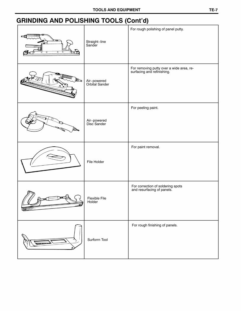
Straight−lineSander
For rough polishing of panel putty.
Air−poweredOrbital Sander
For removing putty over a wide area, re-surfacing and refinishing.
Air−poweredDisc Sander
For peeling paint.
File Holder
For paint removal.
Flexible FileHolder
For correction of soldering spotsand resurfacing of panels.
Surforrn Tool
For rough finishing of panels.
GRINDING AND POLISHING TOOLS (Cont’d)
TOOLS AND EQUIPMENT TE-7

Master Gauge
Plate Looseness
Two−dimensionaldistance
Center−to−centerHorizontal distance inforward/rearward
Wrong Correct
GENERAL INFORMATION1. BASIC DIMENSIONS
(a) There are two types of dimensions in the diagram.(Three−dimensional distance)
� Straight−line distance between the centers of twomeasuring points.
(Two−dimensional distance)� Horizontal distance in forward/rearward between
the centers of two measuring points.
� The height from an imaginary standard line.
(b) In cases in which only one dimension is given, leftand right are symmetrical.
(c) The dimensions in the following drawing indicateactual distance. Therefore, please use the dimen-sions as a reference.
2. MEASURING(a) Basically, all measurements are to be done with a
tracking gauge. For portions where it is not possibleto use a tracking gauge, a tape measure should beused.
(b) Use only a tracking gauge that has no looseness inthe body, measuring plate, or pointers.
HINT:1. The height of the left and right pointers must be equal.
2. Always calibrate the tracking gauge before measuring orafter adjusting the pointer height.
3. Take care not to drop the tracking gauge or otherwiseshock it.
4. Confirm that the pointers are securely in the holes.
(c) When using a tape measure, avoid twists andbends in the tape.
(d) When tracking a diagonal measurement from thefront spring support inner hole to the suspensionmember upper rear installation hole, measurealong the front spring support panel surface.
Pointer
Center−to−centerstraight−linedistance
Vertical distancein lower surface
Vertical distancein center
Body Looseness
PointerPointer Looseness
Three−dimensionaldistance
Imaginary Standard Line
Front Suspension Member Rear SideUpper Installation Hole
Along BodySurface
Front Spring Support Inner Hole
Tape Measure
BODY DIMENSIONSDI-2

mm (in.)
ENGINE COMPARTMENT
Symbol Nomenclature Hole dia.
BO1788
A, a Front fender installation nut−front 8 (0.31)B, b Front spring support hole−rear 11 (0.43)
C, c Front fender installation nut−rear 8 (0.31)D Cowl top panel center mark
E, e Front side member standard hole 15 (0.59)
F, f Suspension member rear installation hole−upper 17 (0.67)G, g Retractable light bracket installation nut−upper 11 (0.43)H, h Radiator seal installation hole−lower 7 (0.28)I, i Front fonder aide installation hole 8 (0.31)
J, j Cowl top panel standard hole 10 (0.39)K Hood lock support brace installation nut 7 (0.28)
BODY DIMENSION DRAWINGS
BODY DIMENSIONS DI-3

mm (in.)
Front
X, x Point
LUGGAGE COMPARTMENT
Symbol Nomenclature Hole dia.
BO1790
V Back door opening frame center mark 2 (0.08)W, w Rear suspension spring support hole−inner 9 (0.35)X, x Rear floor pan bumper installation hole−front 40 (1.57)
BODY DIMENSIONS DI-3

BO
1789
Wheel base 2,595 (102.17)
ImaginaryStandardline
UN
DE
R B
OD
Y
mm (in)
Hole dia.
10 (0.39)
19 (0.75)
18 (0.71)
25×18(0.98×0.71)
18 (0.71)
Nomenclature
Front floor No. 2 reinforcement standard hole
Suspension member front installation hole−outer
Center floor side member standard holeSuspension member rear installation hole
Rear floor side member standard hole
Symbol
Q,q
R, r
S, s
T, t
U, u
Hole dia15 (0.59)
17×15 (0.67×0.59)
11 (0.43)
17 (0.67)
17 (0.67)
10 (0.39)
Nomenclature
Front side member bumper front installation hole−Lower
Front side member bumper front installation hole−LowerStabilizer front installation nut
Suspension member front installation hole−lower
Suspension member rear installation hole−lower
Front floor under reinforcement standard hole
Symbol
LI
M, m
N, n
O,o
P, p
BO
DY
DIM
EN
SIO
NS
DI-3
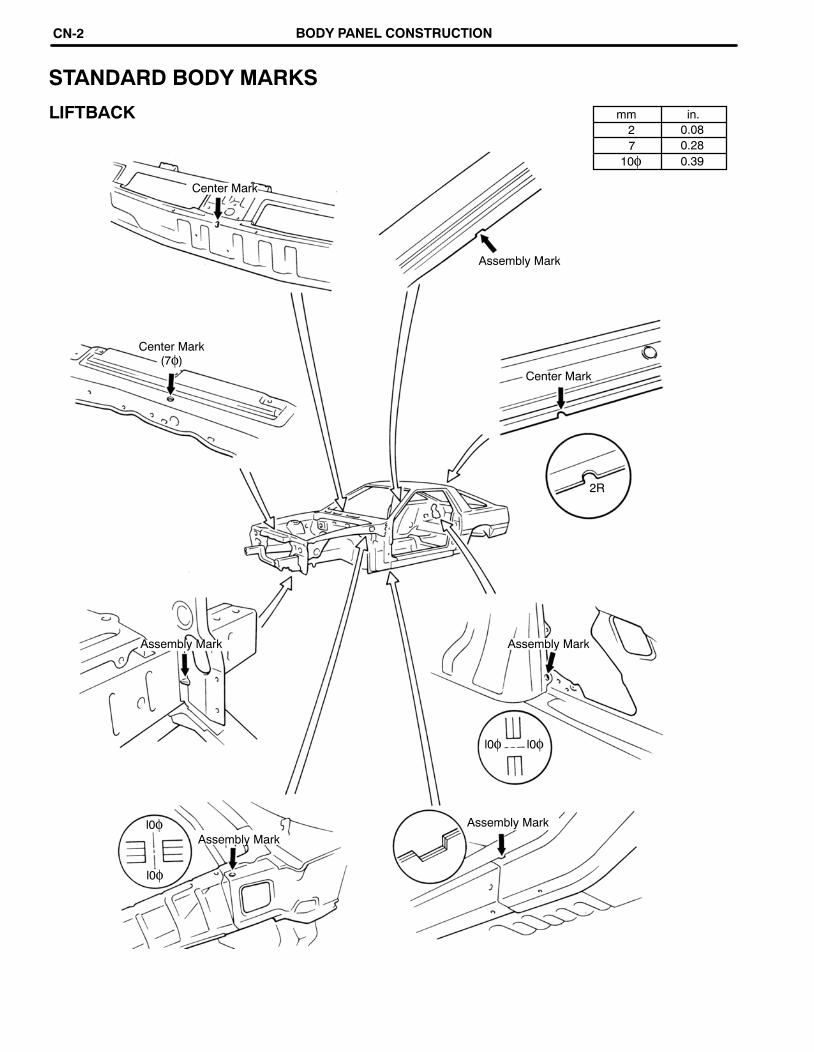
mm in.2 0.087 0.28
10φ 0.39
l0φ
l0φ
l0φ
2R
Center Mark
STANDARD BODY MARKS
LIFTBACK
Assembly Mark
Center Mark(7φ)
Center Mark
Assembly MarkAssembly Mark
Assembly MarkAssembly Mark
l0φ
BODY PANEL CONSTRUCTIONCN-2

Door Side ImpactProtection Beam(USA, Canada, Saudi Arabia andAustralia)Front Bumper Reinforcement
Front Apron to CowlSide Upper Member
Front BodyOuter Pillar
Front side Member
Front Floor UnderReinforcement
Front CrossmemberNo. 2 Reinforcement
Rear BumperReinforcement
Belt AnchorReinforcement
Rear FloorSide Member
Rear SuspensionSpring Support
Front SpringSupport Plate
Belt Anchor to RoofSide Inner Reinforcement
Cowl Top toApron Brace
Quarter Pillar InnerReinforcement
Back Door HingeReinforcement
Quarter WheelHousing No. 1 Gusset
Front Body Pillar UpperInner Reinforcement
Hood StopperReinforcement
Back Door LowerOuter Panel
Engine Hood PanelBack Door UpperOuter Panel
The handling of HSS is the same as for mild steel, but the following should be observed.
HIGH−STRENGTH STEEL (HSS) PARTSGenerally, High−Strength Steel (HSS) is that which has an intensity value of at least 35 kg f/mm2, anddistinguished from mild steel.
1. Panel Hammering; Because HSS is thinner than mild steel, care should be taken to avoid warpingduring hammering operations.
2. Removing Stop Welds: Because HSS is tougher than mild steel, damage will occur more easily to aregular drill. Therefore, an HSS Spot Cutter is recommended.Also, use a high−torque drill at low speed, and supply grinding oil to the drill during use.
3. Panel Welding: Panel welding procedures for HSS are exactly the same as for mild steel. Plugwelding should be done with a MIG (Metal Inert Gas) welder. Do not gas weld or braze panels atareas other than specified.
BODY PANEL CONSTRUCTION CN-3

FRONT CROSSMEMBER (ASSY)
REMOVAL
BODY PANEL REPLACEMENTRE-2

INSTALLATION
1. Temporarily installing the new part and measureeach part in accordance with the body dimen-sion diagram.
BODY PANEL REPLACEMENT RE-3

RADIATOR SUPPORT (ASSY)
Cut the weld points from the back side.
REMOVAL
BODY PANEL REPLACEMENTRE-4

INSTALLATION
Assembly Mark
1. Temporarily install the new part with the assemblymark and measure each part in accordance withthe body dimension diagram.
BODY PANEL REPLACEMENT RE-5

RADIATOR UPPER SUPPORT (ASSY)
REMOVAL
BODY PANEL REPLACEMENTRE-6

NOTE: Install the new panel with the hood locksupport.
INSTALLATION
1. Temporarily install the new part and measureeach part in accordance with the body dimen-sion diagram.
BODY PANEL REPLACEMENT RE-7

FRONT FENDER APRON (ASSY)
REMOVAL
BODY PANEL REPLACEMENTRE-8

INSTALLATION
Assembly Mark
1. Determine the installation position of the newpart by the assembly mark.
2. Measurements must be accurate with the bodydimension diagram, as this effects the frontwheel alignment.
NOTE: The position of the front spring supporthole is very important3. Check the fit of the front fender and hood.
BODY PANEL REPLACEMENT RE-9

FRONT FENDER APRON (CUT−H)
REMOVAL
Rough Cut
1. After removing the spot welds, rough cut thefront fender apron shown above.
BODY PANEL REPLACEMENTRE-10

INSTALLATIONCut for supply part
Cut Location
Cut Location
1. Cut the supply part shown above.
BODY PANEL REPLACEMENT RE-11

FRONT SIDE MEMBER (ASSY)
REMOVAL
BODY PANEL REPLACEMENTRE-12

NOTE: Make sure each measurement is correct,as this part effects the front wheel alignment.
INSTALLATION
Assembly Mark
Front Side Member Plate
1. Temporarily install the new part and measureeach part in accordance with the body dimen-sion diagram.
BODY PANEL REPLACEMENT RE-13

mm in.15 0.5920 0.7960 2.36
FRONT SIDE MEMBER (CUT−P)
REMOVAL
Standard Hole (15φ)
Cut LocationCut Location
Standard Hole (15φ)
60 mm
20 mm
NOTE: Be careful not to damage thereinforcement when cutting the sidemember.
[Ex. USA and Canada][USA and Canada]
1. Before cutting the side member, remove thebattery carrier support. (LH only)
2. Cut the front side member as shown above.NOTE: Be careful not to damage the reinforce-ment when cutting the side member.
BODY PANEL REPLACEMENTRE-14
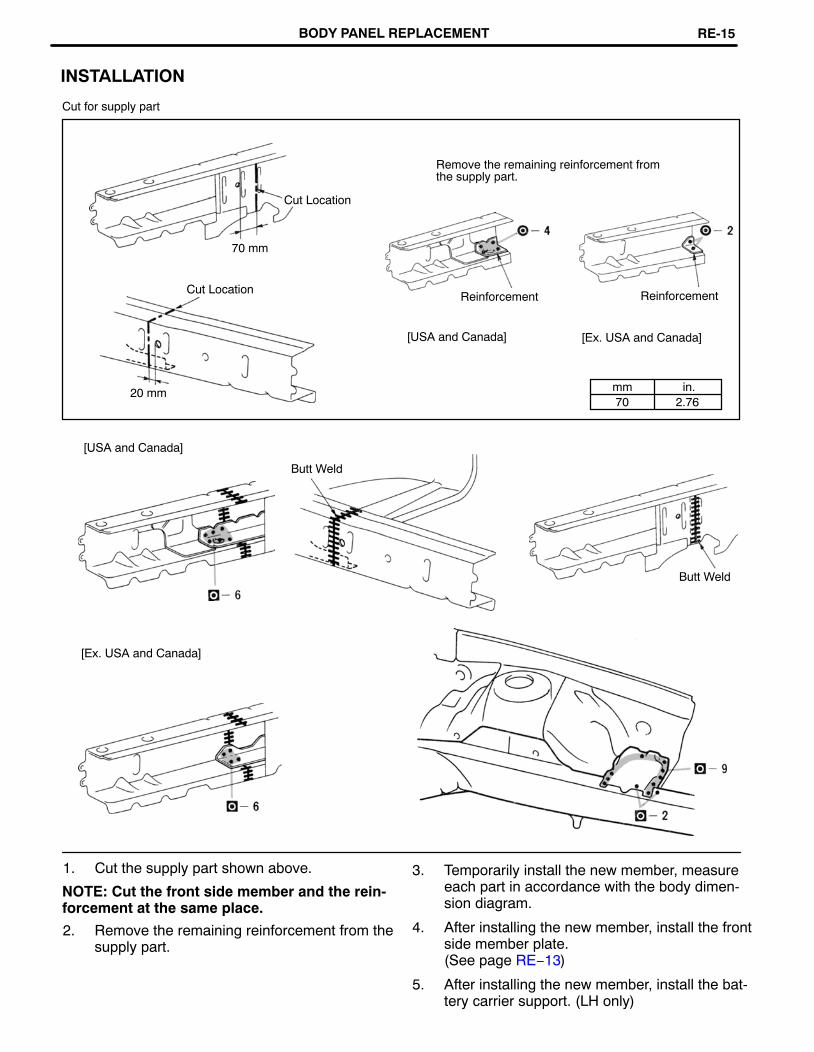
mm in.70 2.76
20 mm
[Ex. USA and Canada][USA and Canada]
Cut LocationReinforcement Reinforcement
70 mm
Cut Location
Remove the remaining reinforcement fromthe supply part.
NOTE: Cut the front side member and the rein-forcement at the same place.
2. Remove the remaining reinforcement from thesupply part.
INSTALLATION
Cut for supply part
[USA and Canada]
Butt Weld
Butt Weld
[Ex. USA and Canada]
1. Cut the supply part shown above. 3. Temporarily install the new member, measureeach part in accordance with the body dimen-sion diagram.
4. After installing the new member, install the frontside member plate.(See page RE−13)
5. After installing the new member, install the bat-tery carrier support. (LH only)
BODY PANEL REPLACEMENT RE-15

COWL TOP SIDE PANEL (ASSY)
REMOVAL
Cut with disc sander etc.
BODY PANEL REPLACEMENTRE-16
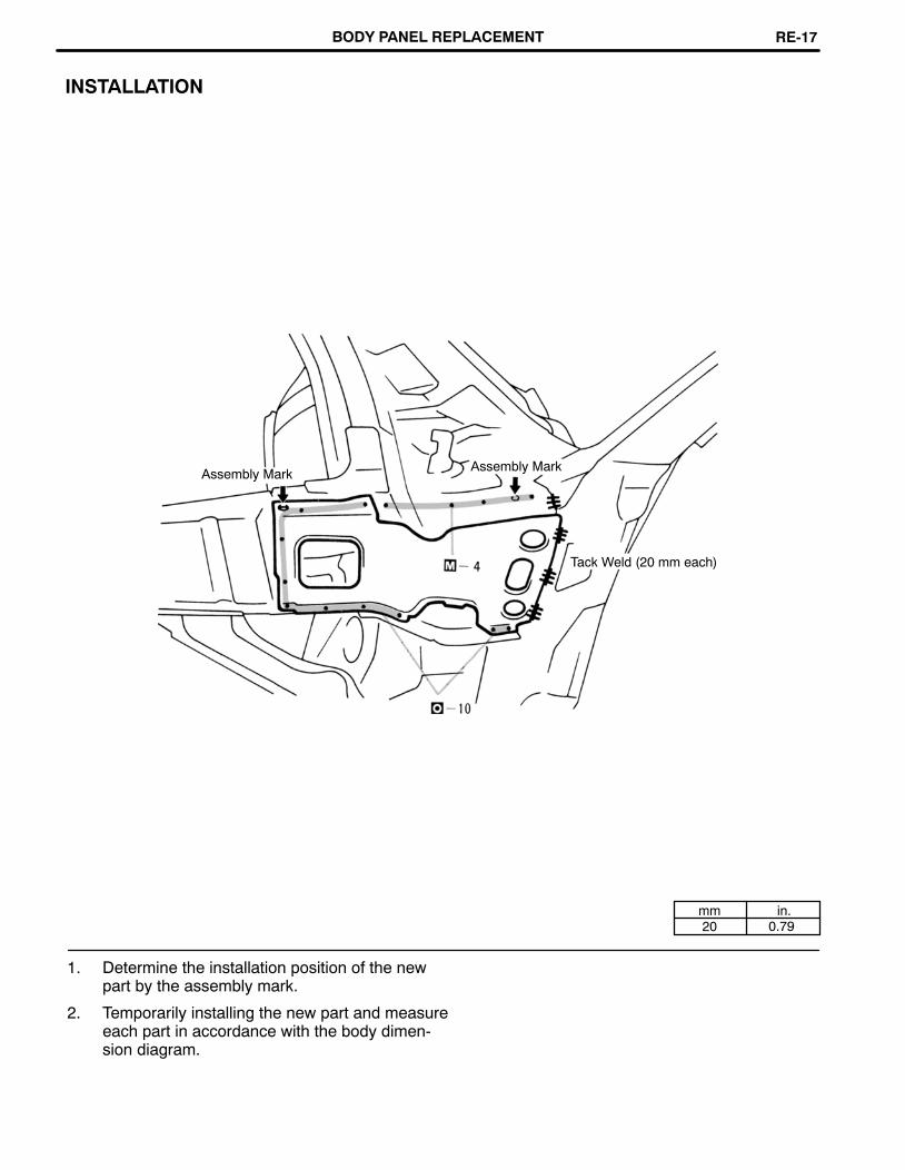
mm in.20 0.79
INSTALLATION
Assembly MarkAssembly Mark
Tack Weld (20 mm each)
1. Determine the installation position of the newpart by the assembly mark.
2. Temporarily installing the new part and measureeach part in accordance with the body dimen-sion diagram.
BODY PANEL REPLACEMENT RE-17

mm in.150 5.91
FRONT BODY PILLAR (CUT)
REMOVAL
150 mm or more [Cut and Join Location]Cut and JoinLocation
Cut With DiscSander etc.
1. Cut and join the front body pillar at the locationshown above.
NOTE:1) As shown above, cut and join the front body
pillar outer and inner panels at a positionshifted about 50 mm (1.97 in.).
2. Remove the remaining roof drip channel frombody side.
BODY PANEL REPLACEMENTRE-18

mm in.20 0.79
790 31.10791 31.14946 37.24
1,162 45.751,402 55.201,407 55.39
INSTALLATION
Butt Weld
[Reference]
(mm)
Tack Weld(20 mm each)
1. Temporarily install the new part and check the fitof the front door, front fender, hood and wind-shield glass.
BODY PANEL REPLACEMENT RE-19

mm in.140 5.51
OUTER ROCKER PANEL (CUT)
REMOVAL
140 mm
Cut and Join Location
[Cut and Join Location]
1. Cut and join the outer panel at the area as showabove.
BODY PANEL REPLACEMENTRE-20

INSTALLATION
Butt Weld
1. Temporarily install the new panel and check thefit for the front door and front fender.
2. There will be less warp if the cut edge (30 − 40mm or 1.18 − 1.57 in.) is adhered to the match-ing part before welding.
NOTE: Scrape off the film on the cut edge and ap-ply weld−through primer to adhere the matchingpart.
BODY PANEL REPLACEMENT RE-21

ROOF PANEL (ASSY)
REMOVAL
Arc Brazing(both sides)
Braze (both sides)
Braze (both sides)
1. Heat the brazed area of the front pillar andscrape off the brazing with a wire brush.
NOTE: Be careful not to overheat the pillar.2. Cut off the roof panel tip at the quarter panel are
brazing connection with a cut grinder.
BODY PANEL REPLACEMENTRE-22

2. Braze the front body pillar connection.NOTE: Before performing these operations,place a wet rag on the roof panel to protect itfrom damage.
INSTALLATION
Body Sealer (6 points)
Braze (both sides)
Body Sealer (8 points)
Braze (both sides)
1. Before temporarily installing the new part,apply body sealer to the windshield headerpanel, roof panel center reinforcement andback window opening frame.
NOTE:1) Apply just enough sealer for the new part
to make contact.
2) For other sealing points, refer to sectionSU.
BODY PANEL REPLACEMENT RE-23

FRONT DOOR OUTER PANEL (ASSY)
REMOVAL
Hemming Location
Heat slightly(USA, Canada, Saudi Arabia andAustralia)
Disc Sander
1. Grind out the hemming location, and remove theouter panel.
2. Slightly heating the outer panel will soften thesealer and make removal easier. (USA, Canada,Saudi Arabia and Australia).
BODY PANEL REPLACEMENTRE-24

mm in.10 0.39
3. Bend the flange hem approx. 30° with a hammerand dolly. Then use a hemming tool.
NOTE:1) Perform hemming in three steps, being care-
ful not to warp the panel.
2) It a hemming tool cannot be used, hem with ahammer and dolly.
INSTALLATION
Assembly MarkAssembly Mark
About 10 mm
Do not close thedrain hole.Body Sealer Body Sealer (6 points)
(USA, Canada, Saudi Arabia andAustralia)
Cloth Tape
30 °
Hemming Tool
1. Before temporarily installing the new part, coatthe back side of the new panel with body sealer.
NOTE:1) Coat evenly about 10 mm (0.39 in.) from the
flange and 3 mm (0.12 in.) in diameter
2) For other sealing points, refer to section SU.
3) Determine the position for the new panel bythe assembly marks.
BODY PANEL REPLACEMENT RE-25

mm in.87 3.43
200 7.87
QUARTER PANEL (CUT)
REMOVALCut and Join Location
Cut and Join Location200 mm
80 mm
[Cut and Join Location]
Front
Braze
Rear
1. Cut and join the quarter panel as shown above.
BODY PANEL REPLACEMENTRE-26

mm in.5 0.20
NOTE:1) Apply sealer approx. 5 mm (0.20 in.) from the
flange, avoiding any oozing.
2) Apply evenly, approx. 3 − 4 mm (0.12−0.16in.) in diameter.
3) For other sealing points, refer to section SU.
INSTALLATION
Butt Weld
Butt Weld
Body Sealer
Braze
Body Sealer
About 5 mm
1. Before temporarily installing the new part,apply body sealer to the wheel arch portion.
2. Temporarily install the new part and check the fitof the front door, luggage compartment door andrear combination lamp.
BODY PANEL REPLACEMENT RE-27

QUARTER PANEL (CUT−P)
REMOVAL
About 335 mm
Cut and JointLocation
Cut and JointLocation
* This section is a cut and join location only.Refer to RE−26 for weld points.
1. Cut on the line shown above.
BODY PANEL REPLACEMENTRE-28

INSTALLATION
Butt Weld
Body SealerAfter butt welding,apply body sealer
ButtWeld
Body Sealer
About 5 mm
* This section is a cut and join location only.Refer to RE−27 for weld points.
1. Before cutting the overlap areas, check the fitfor the luggage compartment door and rearcombination lamp.
2. Before welding, apply body sealer from insideof the vehicle.
NOTE:1) Do not apply body sealer to the weld seams
before welding as the sealer will melt, re-sulting in a bad seal and a bad weld.
2) For other sealing points, refer to section SU.
3. Surface finish the weld seam from the insidealso.
NOTE: Be careful not to grind off to much weld asit will result in loss of durability.
BODY PANEL REPLACEMENT RE-29

BODY LOWER BACK PANEL (ASSY)
REMOVAL
Braze (both sides)
(both sides)
(both sides)
BODY PANEL REPLACEMENTRE-30

INSTALLATION
Braze (both sides)
(both sides)
(both sides)
1. Temporarily install the new part and check thefit of the back door and rear combination lamp.
BODY PANEL REPLACEMENT RE-31

QUARTER WHEEL HOUSING OUTER PANEL (ASSY)
REMOVAL
Roof Side Inner toWheel Housing Brace
1. Before removing the quarter wheel housing out-er panel, remove the roof side inner to wheelhousing brace.
BODY PANEL REPLACEMENTRE-32

INSTALLATION
Assembly MarkAssembly Mark
1. Determine the position of the new part by theassembly marks of the inner and outer panels.
2. Before welding the new part, temporarily installthe quarter panel and check the fit.
BODY PANEL REPLACEMENT RE-33

REAR FLOOR PAN (CUT)
REMOVAL
Cut Location
(RH)(LH)
1. Cut and join the rear floor pan shown above.
2. Avoid the rear floor side member.
3. Since each bracket is supplied separated,remove the brackets if reusing.
BODY PANEL REPLACEMENTRE-34

Body Sealer
Adhere
INSTALLATIONCut Locations
Plug Weld
New Part
NOTE: Be sure the portion to be welded are alignand not loose.5. Coat the overlapping opening portion from the
both sides with body sealer.
1. Cut the new panel shown above.
2. Match the bracket to the new part location(dent marks) and install.
3. After temporarily installing the new part,measure each part in accordance with thebody dimension diagram.
4. Plug weld the overlapping portion of the newpart.
BODY PANEL REPLACEMENT RE-35

REAR FLOOR SIDE MEMBER (ASSY)
REMOVAL
1. Before removing the rear floor side member,remove the rear floor pan.
BODY PANEL REPLACEMENTRE-36

INSTALLATION
1. Temporarily install the new part and measureeach part in accordance with the body dimen-sion diagram.
BODY PANEL REPLACEMENT RE-37

CENTER FLOOR SIDE MEMBER (ASSY)
REMOVAL
BODY PANEL REPLACEMENTRE-38

INSTALLATION Differential Support MemberMounting Reinforcement
Quarter Wheel Housing No.1 Gusset
1. Temporarily install the new part and measureeach part in accordance with the body dimen-sion diagram.
Flexible Hose Bracket
BODY PANEL REPLACEMENT RE-39

CENTER FLOOR NO. 2 CROSSMEMBER (ASSY)
REMOVAL
BODY PANEL REPLACEMENTRE-40

INSTALLATION
BODY PANEL REPLACEMENT RE-41

57161
53291C53932
5320953203
53291C
5370253258
53633532575380253202
53287B (RH)53288B (LH)
53205
53723A (RH)53724A (LH)53801
5570153701
55713A (RH)55714A (LH)
53385A (RH)53386A (LH) 53899B
55101
55748A
53301
Code Part Name Code Part Name
5320253203 Radiator Support Sub−Assy
53723A53724A Front Spring Support Reinforcement
53205 Radiator Upper Support Sub−Assy 5380153802 Front Fender Sub−Assy
53209 Hood Lock Brace Sub−Assy
5325753258 Front End Panel Mounting Bracket
53899B Front Fender Panel Support53932 Front End Panel Sub−Assy
53287B53288B Radiator Support Extension
55101 Dash Panel Sub−Assy55701 Cowl Panel Sub−Assy
53291C Radiator Support to Frame Seal 55713A55714A Cowl Top Side Panel
53301 Hood Sub−Assy53385A53386A Hood Bumper Retainer
55748A Cowl Top Inner to Pillar Brace55748A Cowl Top Inner to Pillar Brace
53633 Hood Lock Control Cable Shield 57161 Front Crossmember
5370153702 Front Fender Apron Sub−Assy
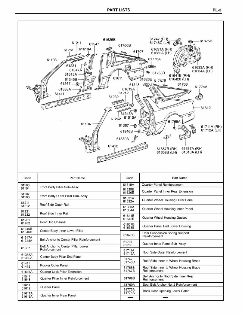
PART LISTSPL-2
61617A (RH)61618A (LH)
61412
61389A
61346B61711A (RH)61712A (LH)
613676110461769A
61262
61348A
61612
61232
61388A61212
61619A61774A
6154861367 61708
61641B (RH)616428 (LH)
61515A61611 61626E
61768B
61633A (RH)61634A (LH)
61231
61103
6170761261 61619A61766B6154761211 61675B61625E
61515A
61411
61345B
61347A
61767B
61773A
61631A (RH)61632A (LH)
61747 (RH)61748C (LH)
61657B (RH)61658B (LH)
Code Part Name Code Part Name
6110361104 Front Body Pillar Sub−Assy
61619A Quarter Panel Reinforcement
61625E61626E Quarter Panel Inner Rear Extension
6110761108 Front Body Outer Pillar Sub−Assy
61631A61632A Quarter Wheel Housing Outer Panel
6121161212 Roof Side Outer Rail
61633A61634A Quarter Wheel Housing Inner Panel
6123161232 Roof Side Inner Rail
61641B61642B Quarter Wheel Housing Gusset
6126161262 Roof Drip Channel
61657B61658B Quarter Panel End Lower Housing
61345B61346B Center Body Inner Lower Pillar
61675BRear Suspension Spring SupportReinforcement61347A
61348A Belt Anchor to Center Pillar Reinforcement6170761708 Quarter Inner Panel Sub−Assy
61367 Belt Anchor to Center Pillar LowerReinforcement 61711A
61712A Roof Side Outer Reinforcement61388A61389A Center Body Pillar End Plate
6174761748C Roof Side Inner to Wheel Housing Brace
6141161412 Rocker Outer Panel
61766B61767B
Roof Side Inner to Wheel Housing BraceReinforcement61515A Quarter Lock Pillar Extension
6154761548 Quarter Pillar Inner Reinforcement 61768B
Belt Anchor to Roof Side Inner RearReinforcement
6161161612 Quarter Panel
61769A Seat Belt Anchor No. 2 Reinforcement
61773A61774A Back Door Opening Lower Patch
61617A61618A Quarter Inner Rear Panel
PART LISTS PL-3

5725757106A57418
5725757402
57102 5168157426
5707257044 5780557805 58149A576495710157105A
57425 58273B 5740258272B57071 LHD57043 57632B 5743657631B57401 57475 5774757435 57602
57648 5760158139A57523
574645168157737
57475
5745157407
57405A57463
58029A58142
58208F58101F 58101F
57467A58264B 58207F58111 58173
57469A58212C58142
7466A
57673 58275C
583465817357468A
58367
58314F57457C
58101A
58109A58193 57465A
58311
58313F
58311E5818358102A
58364B5830558183 58364B58307
58208
57656A
57417
PART LISTSPL-4

Code Part Name Code Part Name
51681 Flexible Hose Bracket 57656A Exhaust Pipe Mounting No. 1 Bracket
5704357044
Front Side Member Rear Reinforcement57673 Rear Seat Back Hinge Mounting Bracket5773757747
Differential Support Member MountingReinforcement57071
57072 Torque Rod Rear Box Sub−Assy57805 Belt Anchor Reinforcement Sub−Assy
5710157102 Front Side Member Sub−Assy
58029A Parking Brake Cable No. 1 Clamp58101A Transmission Auxiliary Cover
57105A57106A Front Side Member Plate Sub−Assy.
58101F Mounting Floor No. 1 Bracket58102A Front Floor Reinforcement Sub−Assy
57257 Engine Rear Support Member Bracket 58109A Parking Brake Retainer Sub−Assy5740157402 Main Floor Side Member Sub−Assy
58111 Front Floor Pan
58139A58149A Front Floor Side Rear Plate57405A Center Floor No. 2 Crossmember Sub−Assy
57407 Center Floor No. 1 Crossmember Sub−Assy58142
Floor Side Member to Floor PanReinforcement57417
57418 Front Floor Under Reinforcement58173 Front Floor Stone Deflector
5742557426 Front Floor No. 2 Reinforcement
58183 Front Seat Mounting Inside Bracket58193 Instrument Panel Brace Mounting Bracket
5743557436 Center Floor Side Member 58207F
58208F Parking Brake Cable Clamp Sub−Assy
57451 Front Floor Crossmember 58208 Center Floor Pan57457C Front Outside Mounting Front Bracket 58212C Center Floor Front Pan57463 Center Floor No. 3 Crossmember 58264B Parking Bake Cable Guide No. 1 Bracket57464 Center Floor Crossmember Strength 58272B Belt Anchor to Floor Pan No. 4 Reinforcement57465A57466A Center Floor Crossmember Rear Gusset
58273B Belt Anchor to Floor Pan No. 5 Reinforcement58275C Wire Harness Protector Bracket
57467A Front Seat Outside Mounting Front Bracket 58305 Spare Wheel Clam Bracket Sub−Assy57468A57469A Front Seat Outside Rear Bracket
58307 Body Lower Back Panel Sub−Assy58311E Rear Floor Service Hole Cover
57475 Front Floor Crossmember Plate 58311 Rear Floor Pan57523 Center Floor Crossmember Brace 58313F
58314F Rear Floor Pan to Quarter Panel Extension5760157602 Rear Floor Side Member Sub−Assy
58364 Rear Floor Heat Insulator Bracket57631B57632B Rear Floor Side Member Front Reinforcement
58364B Fuel Tank Support Bracket58367 Fuel Tube Clamp Bracket
5764857649 Quarter Wheel Housing No. 1 Gusset
PART LISTS PL-5

67001 (RH)67002 (LH)
61111 (RH)61112 (LH)
67005
63102A
63104
63105A
63111
Code Part Name Code Part Name
63102A Windshield Header Panel Sub−Assy 6700167002 Front Door Panel Sub−Assy
63104 Roof Panel Center Reinforcement Sub−Assy63105A Back Door Opening Frame Sub−Assy 67005 Back Door Panel Sub−Assy
63111 Roof Panel 6711167112 Front Door Outer Panel
PART LISTSPL-6
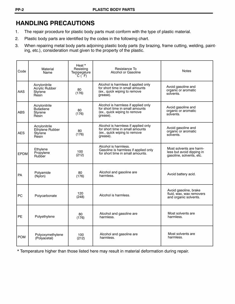
CodeMaterialName
Heat *Resisting
Temperature°C (°F)
Resistance ToAlcohol or Gasoline Notes
AAS
AcrylonitrileAcrylic RubberStyreneResin
80(176)
Alcohol is harmless if applied onlyfor short time in small amounts(ex., quick wiping to removegrease).
Avoid gasoline andorganic or aromaticsolvents.
ABS
AcrylonitrileButadieneStyreneResin
80(176)
Alcohol is harmless if applied onlyfor short time in small amounts(ex., quick wiping to removegrease).
Avoid gasoline andorganic or aromaticsolvents.
AES
AcrylonitrileEthylene RubberStyreneResin
80(176)
Alcohol is harmless if applied onlyfor short time in small amounts(ex., quick wiping to removegrease).
Avoid gasoline andorganic or aromaticsolvents.
EPDMEthylenePropyleneRubber
100(212)
Alcohol is harmless.Gasoline is harmless if applied onlyfor short time in small amounts.
Most solvents are harm-less but avoid dipping ingasoline, solvents, etc.
PAPolyamide(Nylon)
80(176)
Alcohol and gasoline areharmless. Avoid battery acid.
PC Poiycarbonate120
(248) Alcohol is harmless.Avoid gasoline, brakefluid, wax, wax removersand organic solvents.
PE Polyethylene80
(176)Alcohol and gasoline areharmless.
Most solvents areharmless.
POMPolyoxymethylene(Polyacetal)
100(212)
Alcohol and gasoline areharmless.
Most solvents areharmless.
HANDLING PRECAUTIONS1. The repair procedure for plastic body parts must conform with the type of plastic material.
2. Plastic body parts are identified by the codes in the following chart.
3. When repairing metal body parts adjoining plastic body parts (by brazing, frame cutting, welding, paint-ing, etc.), consideration must given to the property of the plastic.
* Temperature higher than those listed here may result in material deformation during repair.
PLASTIC BODY PARTSPP-2

Code MaterialName
Heat *Resisting
Temperature°C (°F)
Resistance ToAlcohol or Gasoline Notes
PP Polypropylene 80(176)
Alcohol and gasoline areharmless.
Most solvents areharmless.
PPOModifiedPolyphenyleneOxide
100(212) Alcohol is harmless.
Gasoline is harmless if applied only for quick wiping to remove grease.
PS Polystyrene 60(140)
Alcohol and gasoline are harm-less if applied only for short timein small amounts.
Avoid dipping or immersing in alcohol,gasoline, solvents, etc.
PURThermosettingPolyurethane
80(176)
Alcohol is harmless if applied only forvery short time in small amounts (ex.,quick wiping to remove grease).
Avoid dipping or immersing in alcohol,gasoline, solvents, etc.
PVCPolyvinylchloride(Vinyl)
80(176)
Alcohol and gasoline are harmless ifapplied only for short time in smallamounts (ex., quick wiping to removegrease).
Avoid dipping or immersing in alcohol,gasoline, solvents, etc.
PMMAPolymethylMethacrylate
80(176)
Alcohol is harmless if applied onlyfor short time in small amounts.
Avoid dipping or immersing in alcohol,gasoline, solvents, etc.
SANStyreneAcrylonitrileResin
80(176)
Alcohol is harmless if applied onlyfor short time in small amounts(ex., quick wiping to removegrease).
Avoid dipping or immersing in alcohol,gasoline, solvents, etc.
SMCSheetMoldingCompound
180(356)
Alcohol and gasoline areharmless. Avoid alkali
TPOThermoplasticOlefine
80(176)
Alcohol is harmless.Gasoline is harmless if applied onlyfor short time in small amounts.
Most solvents are harm-less but avoid dipping ingasoline, solvents, etc.
TPUThermoplasticPolyurethane
80(176)
Alcohol is harmless if applied only forvery short time in small amounts (ex.,quick wiping to remove grease).
Avoid dipping or immersing in alcohol,gasoline, solvents, etc.
* Temperature higher than those listed here may result in material deformation during repair.
PLASTIC BODY PARTS PP-3

LOCATION OF PLASTIC BODY PARTS
Fuel Tank Filler Protector (PE)
Safety Pad (PVC/PUR)Roof Headlining(PVC/PUR)
Washer Nozzle (PA)Quarter VentilationLouver (ABS)
Rear Spoiler (SMC)Front Facia Cover (PUR)
Fan Shroud (PP)
Washer Jar (PP)
*1 Rear SideMarker Lamp(PMMA/ ABS)
Room Pressure ReliefValve (PP)
Radiator Grill (ABS)Fuel Tank No. 1 Protector(PE)
Door Scuff Plate (PP)Radiator GrillLower (PP)
Fender Liner (PE)Front Turn SignalLamp (PMMA/PP) *1 Side Marker Lamp (PMMA/ABS)
*2 Side Turn Signal Lamp (SAN/ABS)
Front Bumper Cover (PUR)
Front Spoiler Cover (PUR)
NOTE:• Resin material differs with model./ Made up of 2 or more kinds of materials.*1 USA and Canada*2 Except USA and Canada
PLASTIC BODY PARTSPP-4
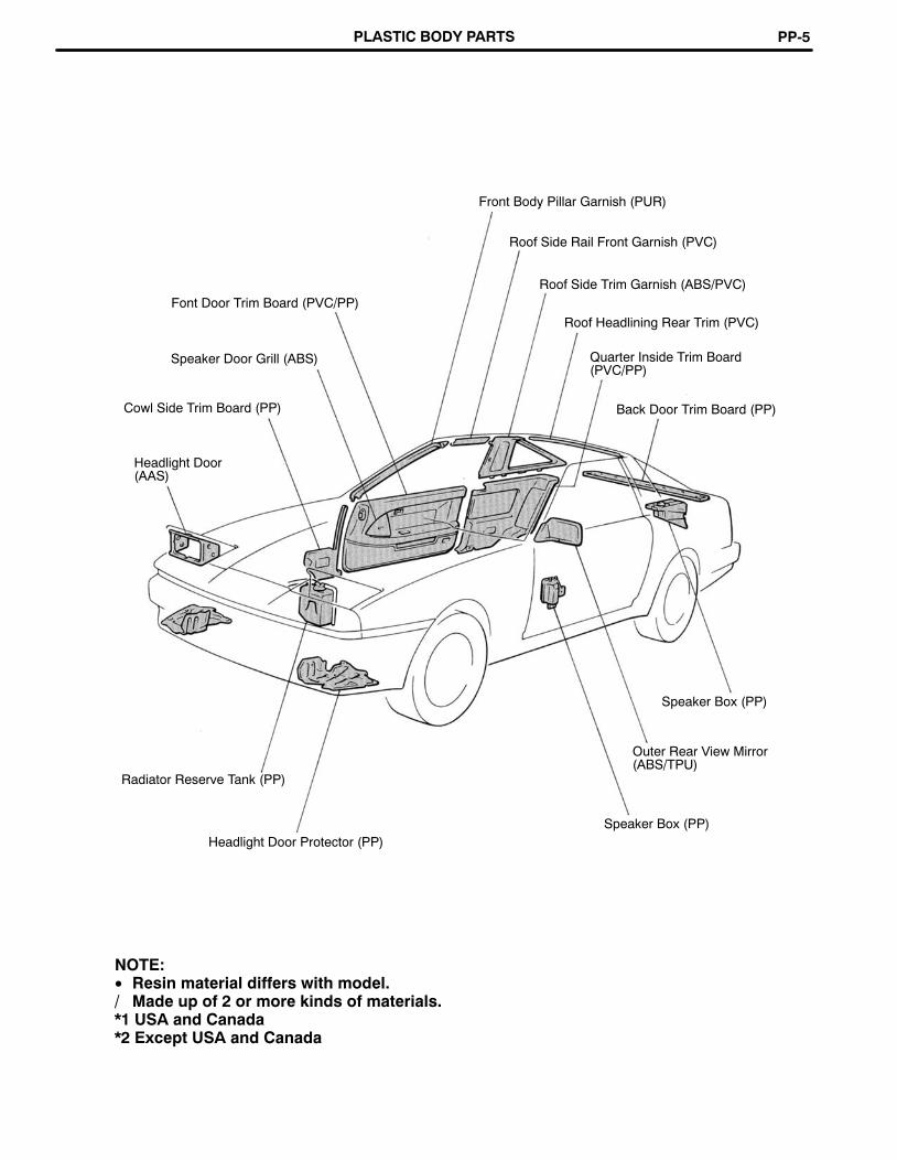
Roof Side Trim Garnish (ABS/PVC)
Front Body Pillar Garnish (PUR)
Roof Side Rail Front Garnish (PVC)
Font Door Trim Board (PVC/PP)
Roof Headlining Rear Trim (PVC)
Speaker Door Grill (ABS) Quarter Inside Trim Board(PVC/PP)
Cowl Side Trim Board (PP) Back Door Trim Board (PP)
Headlight Door(AAS)
Speaker Box (PP)
Outer Rear View Mirror(ABS/TPU)
Radiator Reserve Tank (PP)
Speaker Box (PP)Headlight Door Protector (PP)
NOTE:• Resin material differs with model./ Made up of 2 or more kinds of materials.*1 USA and Canada*2 Except USA and Canada
PLASTIC BODY PARTS PP-5

Deck Trim Side Jack Cover (PP)
Deck Side Trim Panel (PP)
Cooler Unit (PP)Rear Speaker Grill (PP/ABS)Heater Unit (PP)
Heater Blower (PP)Deck Trim Rear Cover (PP)
Deck Trim Side ServiceHole Cover (PP)
Rear CombinationLamp Service Cover(PP)
Font Fender MudGuard (PUR)
Outside Moudling(PVC/PUR)
License Pate Lamp(PMMA/PC)
Lower Back Finish PanelHole Cover (ABS)Side Mud Guard (PUR)
Rear Bumper Cover (PUR)
*1 Rear Marker Lamp (PMMA/ABS) Rear Combination Lamp (PMMA/AES)
Quarter Panel Mud Guard (PUR)
NOTE:• Resin material differs with model./ Made up of 2 or more kinds of materials.*1 USA and Canada
PLASTIC BODY PARTSPP-6

NOTE:1. Prior to applying body sealer, clean the area with a rag soaked in white gasoline.
2. If weld−through primer was used, first wipe off any excess with thinner, and coat with anti−corrosion primer before applying body sealer.
3. Wipe off any excess body sealer with a rag soaked in white gasoline.
BODY PANEL SEALING AREASFor water−proofing and anti−corrosion measures, always apply body sealer to the body panel seams andhems of the doors, hood, etc.
Flat SurfacingFlat Surfacing
BODY PANEL SEALING AND UNDERCOATINGSU-2

After installing the plug hole, apply sealer.
Flat Surfacing
BODY PANEL SEALING AND UNDERCOATING SU-3
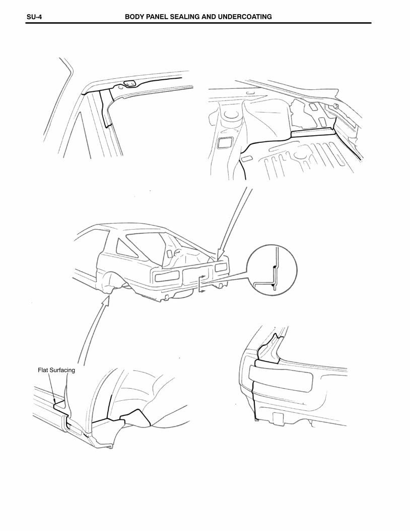
Flat Surfacing
BODY PANEL SEALING AND UNDERCOATINGSU-4

Hood
Front Door Panel
Back Door Panel
Do not close the drain hole.
Flat surfacing
Fuel Inlet Box Fuel Inlet Box Cover
BODY PANEL SEALING AND UNDERCOATING SU-5

BODY PANEL UNDERCOATING AREASTo prevent corrosion and protect the body from damage by flying stones, always apply undercoating to thewelded seams and wheel housings after chassis, under body or panel repair.NOTE:1. First wipe off any dirt, grease or oil with white gasoline.
2. Cover the surrounding areas with masking paper to avoid coating unnecessary areas. If otherareas are accidently coated, wipe off the coating immediately.
3. Do not coat parts which become hot, such as the tail pipe, or moving parts, such as the propel-ler shaft.
4. Besides the locations described below, apply undercoating to all weld points under the body toinsure corrosion prevention.
5. Be sure to seal the edge of the flange of the member and bracket with undercoating.
REFERENCE: Referring to the notes above, undercoating should be applied according to the specificationsfor your country.
BODY PANEL SEALING AND UNDERCOATINGSU-6