1 FIRE Engineering Summary Phil Heitzenroeder for the FIRE Engineering Team Presented to the FIRE...
15
1 FIRE Engineering Summary Phil Heitzenroeder for the FIRE Engineering Team Presented to the FIRE Physics Validation Review Committee March 30, 2004
-
Upload
jemimah-mosley -
Category
Documents
-
view
214 -
download
1
Transcript of 1 FIRE Engineering Summary Phil Heitzenroeder for the FIRE Engineering Team Presented to the FIRE...

1
FIRE Engineering Summary
Phil Heitzenroeder
for the
FIRE Engineering Team
Presented to the FIRE Physics Validation Review Committee March 30, 2004

2
Outline
• FIRE and its Status
• Engineering Evaluations of Coil Systems*
• R&D Plans for the Coil Systems*
• Costs
• Summary
*This talk concentrates on the coil systems since the other key engineering systems
are covered in presentations by B. Nelson and M. Ulrickson.

3
Status• The FIRE study began in late 1999. • All major systems addressed. • Preliminary cost estimates indicate a “green field” cost of $1.19B.• Engineering Peer Reviews were held in June‘01. Included:
– TF and PF coils– Vacuum Vessel and PFCs– Fueling and Pumping – Nuclear effects and Activation– Cryoplant– Facilities and Siting
• Focused set of parameters were adopted; R&D plans have been outlined.
• Participated in and received good feedback from SNOWMASS. – Many of these inputs are now reflected in the design and the FIRE 2003-4
Engineering Report Update • Work so far indicates all major systems can be designed to meet or
exceed requirements.

4
FIRE Engineering Review Critical Issues (June 2001)
CRITICAL DESIGN ISSUES:1. FOCUS in an expeditious manner on 2 Designs along the Q = 10 “zone,” (not the “Baseline” design) that indicate, at the Pre-Conceptual Design level, an Engineering Margin value in the range of 1.2 to 1.3. (Done)This level of margin should also apply to the insulation schemes. (Agreed)2. Then FOCUS, in an expeditious manner on one device, either Wedged or Bucked/Wedged (to be selected by the design team.) Done, Wedged 10T chosen3. Incorporated in the focusing effort should also be the immediate design attention to the details of leads, both TF and CS, associated cooling fittings and design of all other critical systems that are lacking detail at the Pre-Conceptual level - (Not done, limited resources used to address more global issues - I.e.,rep rate)- See the material below and the associated attached chits. (about 1/3 of the chits have been addressed await resources for more detailed items.)CRITICAL R&D ISSUES:1. The qualification of the properties, through R&D of the TF coil Materials (OFHC for the Bucked/Wedged and BeCu for the Wedged device) in sizes and thickness that are representative of those required for fabrication. (Agreed, also Elbrudor for PF, will pursue if CD-0)2. For either device, the qualification, through R&D, of materials, that are available today, for the insulation systems. (Agreed, 4 Small Business Innovative Research grants awarded by DOE for insulation development in support of FIRE/fusion needs.)

5
Modular Tungsten Brush
DivertorsDouble Walled VV
with Integral Shielding.
LN2 Cooled wedged Cu TF Coils
LN2 Cooled Segmented Central Solenoid
Key Components of FIRE
LN2 Cooled Copper
PF Coils

6
Engineering Status of the TF Coil
Stress and fatigue evaluations are performed in accordance with the FIRE Structural Design Criteria.Structural stress allowable exceeds requirements:
– Calculated max. membrane + bending stress: 611 MPa.
– M+B allowable for C17510 BeCu: 724 MPa.
Shear allowable exceeds requirements:•Shear required : 50 MPa.•Shear Developed: 60 MPa. (200 MPa compression; =0.3)
Fatigue life exceeds requirements:– requirement: 3,000 full power shots (H-Mode)
+ 30,000 half power shots (L-Mode). – Evaluation indicates 5,000 full power shots;
half power shots far exceed requirements. Pulse Duration meets requirements: >20s flat-top capability @10T
Structural model showing out of plane displacements

7
Engineering Status of the Central Solenoid and PF Coils
Structural stress allowable exceeds requirements:– 1.5 Sm Allowable for Elbrodur at that
temperature =541; Highest Max. VonMises stress is 414
MPa. at EOB for CS2 coils.
Max. Temperature (at EOC) of 188 K. Is well within temp. limit of 373 K.
Fatigue: more work required.– The FIRE design criteria requires a
Factor of Safety (FS) of 20 on the number of cycles
– The CS-2 coil does not meet this requirement for H-mode operation; its FS is 15.
CS 3
CS 2
CS 1
PF 1
PF 2
Figure 6. Central Solenoid / TF Interface
8
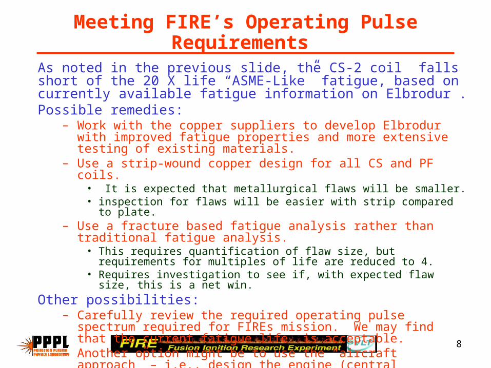
Meeting FIRE’s Operating Pulse Requirements
As noted in the previous slide, the CS-2 coil falls short of the 20 X life “ASME-Like” fatigue, based on currently available fatigue information on Elbrodur .Possible remedies:
– Work with the copper suppliers to develop Elbrodur with improved fatigue properties and more extensive testing of existing materials.
– Use a strip-wound copper design for all CS and PF coils. • It is expected that metallurgical flaws will be smaller.• inspection for flaws will be easier with strip compared to plate.
– Use a fracture based fatigue analysis rather than traditional fatigue analysis.
• This requires quantification of flaw size, but requirements for multiples of life are reduced to 4.
• Requires investigation to see if, with expected flaw size, this is a net win.
Other possibilities: – Carefully review the required operating pulse spectrum required for
FIREs mission. We may find that the current fatigue life is acceptable. – Another option might be to use the “aircraft approach” – i.e., design the
engine (central solenoid) to be readily replaced while still within its safe operating lifetime.

9
Coil R&D Highlights
• FIRE’s magnet systems have relatively modest R&D needs:– Cryo cooled copper design.– Much data to draw upon from CIT/BPX; IGNITOR; ALCATOR
C-Mod.
• R&D Focus:– Filling gaps in data bases of materials (Elbrodur; insulators)– R&D which may permit higher performance (refined design
criteria; optimized materials; improved inspection techniques)– Cost reduction (manufacturing process development;
materials selection)– Risk mitigation (component testing; prototypes).

10
TF Copper: BeCu Plate Developed for BPX Should Meet FIRE’s Needs.
•The C17510 BeCu plate shown was produced for BPX by Brush-Wellman.
•Properties and size are very similar to those required for FIRE.
•Brush-Wellman requires modest R&D to establish production details.

11
Copper Joining R&D
C17510 BeCu
C10200 OFHC
• R&D is planned to develop friction stir or e-beam welding for joining the TF copper segments.
• R&D is also planned for electroform welding for possible use in the PF coils.

12
PF Coil Conductor R&D
• The CS and ring coils all use “Elbrodur” CuCrZr copper.
• R&D will focus on:– Processing to optimize fatigue properties. – Inspection techniques to reliably measure flaw
sizes.– Characterization of physical properties for the
Elbrodur conductor in the sizes and forms FIRE plans to use.

13
Radiation Resistant Insulating Materials R&D
Requirements:• FIRE plans 3,000 full power D-T shots producing 5 TJ of
neutrons + 30,000 half power D-D shots producing 0.5 TJ of neutrons.
• End of life peak insulation dose: 1.05 x 10¹⁰ rads.• BPX insulation would meet this requirement
• This is a high leverage area since it has the potential of permitting a greater number of D-T shots . It has a strong bearing on reliability and risk mitigation.
Plans: • Collaborate with several existing SBIR’s which are underway to
develop high radiation resistant insulating materials with good processing characteristics.
• Characterize and life test the friction characteristics of insulating materials required between the CS coils and in the TF coils.

14
Costs

15
Summary
• The FIRE study has addressed all major systems. • Results have been encouraging – no “show stoppers” in technical or
cost areas.• An Engineering Peer Review was held in 2001.
– FIRE adopted a focused set of parameters in FY 01, as recommended.– The other detailed recommendations have been addressed.– Favorable comments about depth of analysis, considering we are in Pre-
Conceptual design phase. • R&D plans have been developed.
– FIRE’s Cryo cooled Cu design has modest R&D requirements; lots of data to draw upon.
– R&D will focus on areas which will reduce uncertainties and costs and can improve performance.
• FIRE participated in and received much feedback from SNOWMASS in ’02. Much of this has been factored into FIRE’s design and plans.
• Preliminary cost estimate is $1.19 B. If a site with modest credits is identified, the $1B cost goal can most likely be achieved.