1 Fiber Optics LINK LOSS BUDGET. 2 Fiber Optics In order to operate properly, a fiber optic network...
21
1 Fiber Optics LINK LOSS BUDGET
-
Upload
moses-bradley -
Category
Documents
-
view
256 -
download
2
Transcript of 1 Fiber Optics LINK LOSS BUDGET. 2 Fiber Optics In order to operate properly, a fiber optic network...
1
Fiber Optics
LINK LOSS BUDGET
2
Fiber Optics
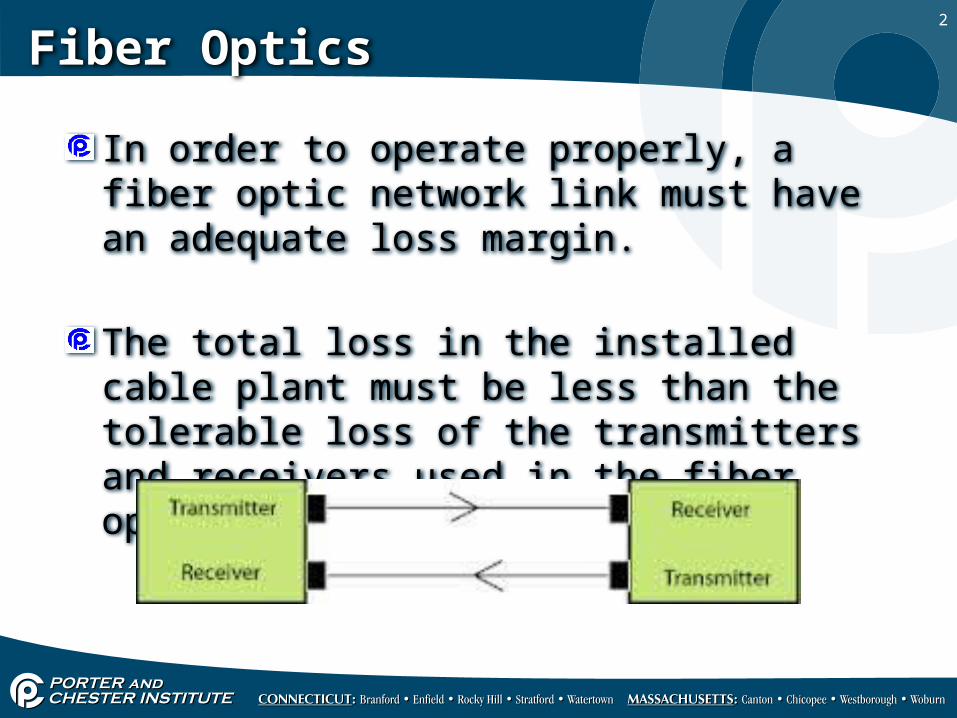
In order to operate properly, a fiber optic network link must have an adequate loss margin.
The total loss in the installed cable plant must be less than the tolerable loss of the transmitters and receivers used in the fiber optic link.
3
Fiber Optics
During the design phase, the cable plant loss must be estimated, based on component specifications an the total cable length, to ensure the chosen equipment will work properly.
Ideally there should be at least 3dB less loss in the cable plant than the link dynamic range to allow for component degradation and potential restoration splicing.
4
Fiber Optics
Receive sensitivity and transmitter power are used to calculate the optical power budget available for the cable.
The first step in evaluating optical power budget is determining how much light is available for the electronic devices.
5
Fiber Optics
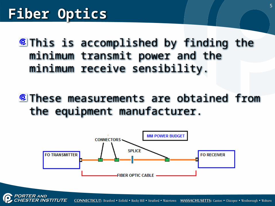
This is accomplished by finding the minimum transmit power and the minimum receive sensibility.
These measurements are obtained from the equipment manufacturer.
6
Fiber Optics
The minimum transmit power is the least amount of transmit power guaranteed by the device.
Some vendors will publish an average transmit power.
Be careful using an average because it does not guarantee the products will perform at that average level.
7
Fiber Optics
To calculate the available light, subtract the minimum receive sensitivity from the minimum transmit power.
The minimum receive sensitivity is usually a negative number, such as -33dBm. Subtracting a negative number is the same as adding its absolute value.
8
Fiber Optics
For example, if a device has a minimum transmit power equal to -10 dBm and a minimum receive sensitivity of -33 dBm, the available power will be 23 dBm
Available light = minimum transmit power minus minimum receive sensitivity
-10 dBm minus (-33 dBm) = 23 dBm
9
Fiber Optics
When connecting devices from different vendors or different product models, the available power calculation needs to be determined for both directions.
The smaller of the two calculations should be used for the amount of available light to ensure performance.
10
Fiber Optics
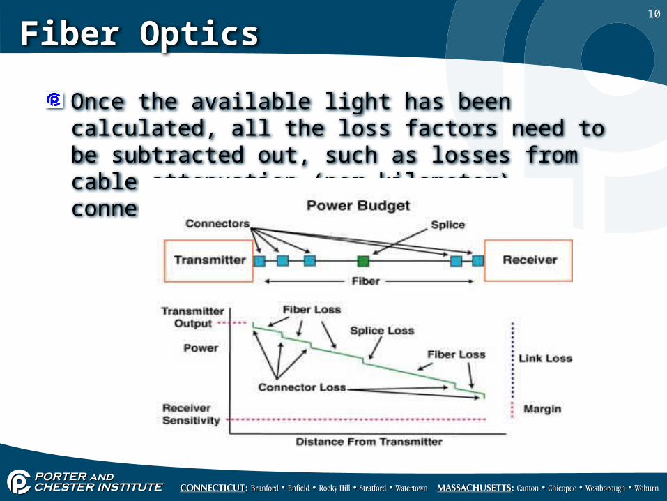
Once the available light has been calculated, all the loss factors need to be subtracted out, such as losses from cable attenuation (per kilometer), connector loss, and cable splices.
11
Fiber Optics
Cable attenuation is the most significant loss and is determined by using the manufacturers worst case loss factor for the type of cable being installed.
This number will range from .22 dB to .5 dB per kilometer for, multiply this number by the number of kilometers.
A fiber with .4dB per kilometer of loss will lose 16 dB over a distance of 40 kilometers.
12
Fiber Optics
Fiber over a certain length will require splicing so you'll need to include additional loss for splicing.
Fiber installers provide a worse case loss number for your calculation, typically each splice will introduce .1 dB of additional loss.
Multiply this number times the number of splices in your fiber.
13
Fiber Optics
Light loss for connectors is another loss factor to consider in your calculation.
The exact number of connectors for the network needs to be determined.
Connector loss is provided by the connector manufacturer and the installer. Multiply the total number of connectors by the loss per connector.
14
Fiber Optics
Each of the factors is subtracted from the original light availability.
If the number is negative there is not enough power to drive the performance of the network.
If the number is positive, you still need to have a buffer for anticipated repairs (additional splices in the network) and temperature extremes.
15
Fiber Optics
This is typically down by using a safety factor in your calculation.
The number differs per organization, but typically a value approximately 3 dB is used.
It acts as a buffer to your power and guards against unforeseen factors affecting your optical power budget.
16
Fiber Optics
When determining the loss budget of cable plant it boils down to;
The length, type and wavelength of fiber used in the link.How many connectors via patch panels are in the link.How many splices are in the link
CABLE + CONNECTORS + SPLICES – DYNAMIC RANGE (POWER) = LINK LOSS MARGIN
17
Fiber Optics
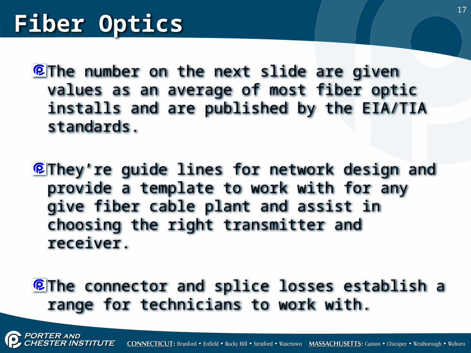
The number on the next slide are given values as an average of most fiber optic installs and are published by the EIA/TIA standards.
They’re guide lines for network design and provide a template to work with for any give fiber cable plant and assist in choosing the right transmitter and receiver.
The connector and splice losses establish a range for technicians to work with.
18
Fiber Optics
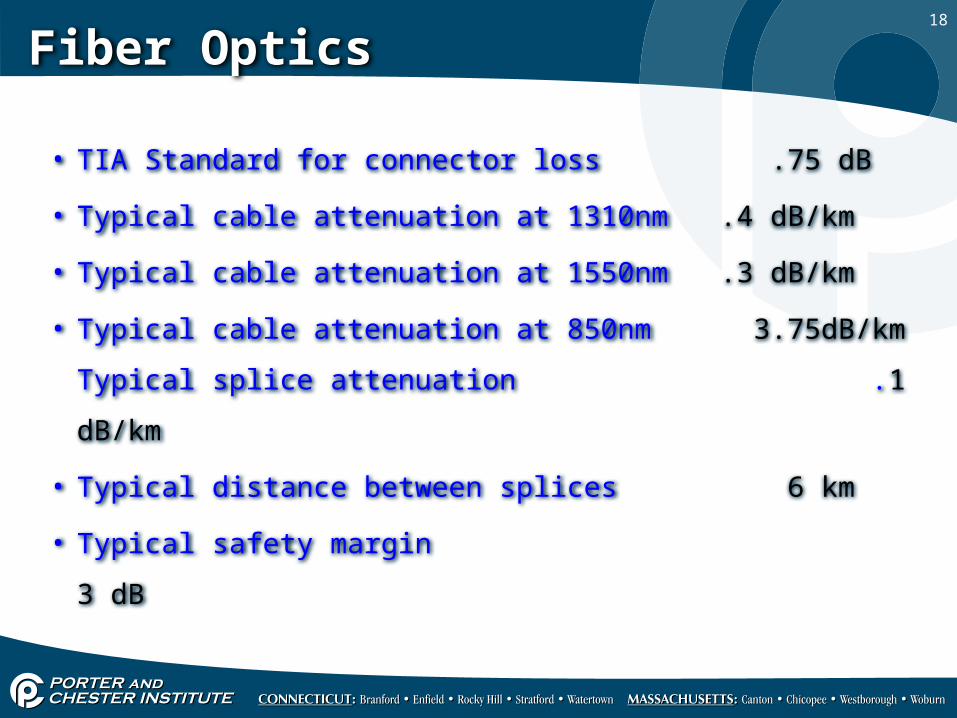
• TIA Standard for connector loss .75 dB
• Typical cable attenuation at 1310nm .4 dB/km
• Typical cable attenuation at 1550nm .3 dB/km
• Typical cable attenuation at 850nm 3.75dB/km
Typical splice attenuation .1 dB/km
• Typical distance between splices 6 km
• Typical safety margin 3 dB
19
Fiber Optics
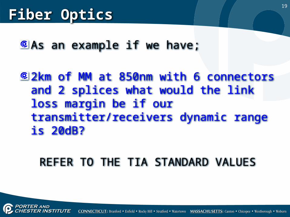
As an example if we have;
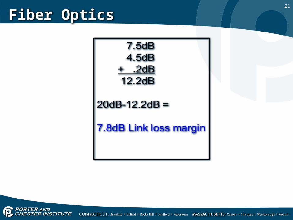
2km of MM at 850nm with 6 connectors and 2 splices what would the link loss margin be if our transmitter/receivers dynamic range is 20dB?
REFER TO THE TIA STANDARD VALUES
20
Fiber Optics
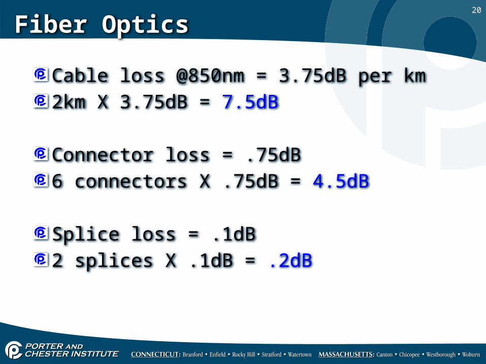
Cable loss @850nm = 3.75dB per km2km X 3.75dB = 7.5dB
Connector loss = .75dB6 connectors X .75dB = 4.5dB
Splice loss = .1dB2 splices X .1dB = .2dB
21
Fiber Optics