1 ECE 4950 – Integrated System Design I ECE 4950 - INTEGRATED SYSTEMS I Design - General Design...
39
1 ECE 4950 – Integrated System Design I ECE 4950 - INTEGRATED SYSTEMS I Design - General Design Approach Timothy Burg
-
Upload
elijah-richard -
Category
Documents
-
view
228 -
download
4
Transcript of 1 ECE 4950 – Integrated System Design I ECE 4950 - INTEGRATED SYSTEMS I Design - General Design...
1ECE 4950 – Integrated System Design I
ECE 4950 - INTEGRATED SYSTEMS I
Design - General Design Approach
Timothy Burg

ECE 495 – Integrated System Design I
Career Note: Communication Skills are Important
• Cover Letter Mistakes - some employers don't bother reading cover letters, most do. – Using the Wrong Cover Letter Format
• Include the date, the recipient's mailing address and your address.
– Not Proofing for Typos and Grammatical Errors• Employers tend to view typos and grammatical errors as
evidence of your carelessness and inability to write. Proofread every letter you send.
– Writing a Novel
http://career-advice.monster.com/resumes-cover-letters/cover-letter-tips/avoid-7-killer-cover-letter-mistakes/article.aspx?key=gsaa

ECE 495 – Integrated System Design I
Career Note: Communication Skills are Important
– Making Unsupported Claims• Too many cover letters from college students and recent
grads say the applicant has "strong written and verbal communication skills." Without evidence, it's an empty boast. Give some examples for each claim you make. Employers need proof.
– Not Sending a Real Cover Letter• Some job seekers type up a one or two-sentence "here's
my resume" cover letter, while others attach handwritten letters or sticky notes.
These same basic concepts apply to your technical writing!You need to show that you care about your work and are competent.
The reason I have you write so much in ECE495 is 1) so you can practice writing and 2) it is required to document your project.

ECE 495 – Integrated System Design I
Design Example – Design Tools are Required
The Mythical Man-Month: Essays on Software Engineering (1982) by Fred Brooks, whose central theme is that "adding manpower to a late software project makes it later"
A large programming project that does not use good design techniques is equivalent to a tar pit swallowing everything that enters.
5ECE 4950 – Integrated System Design I
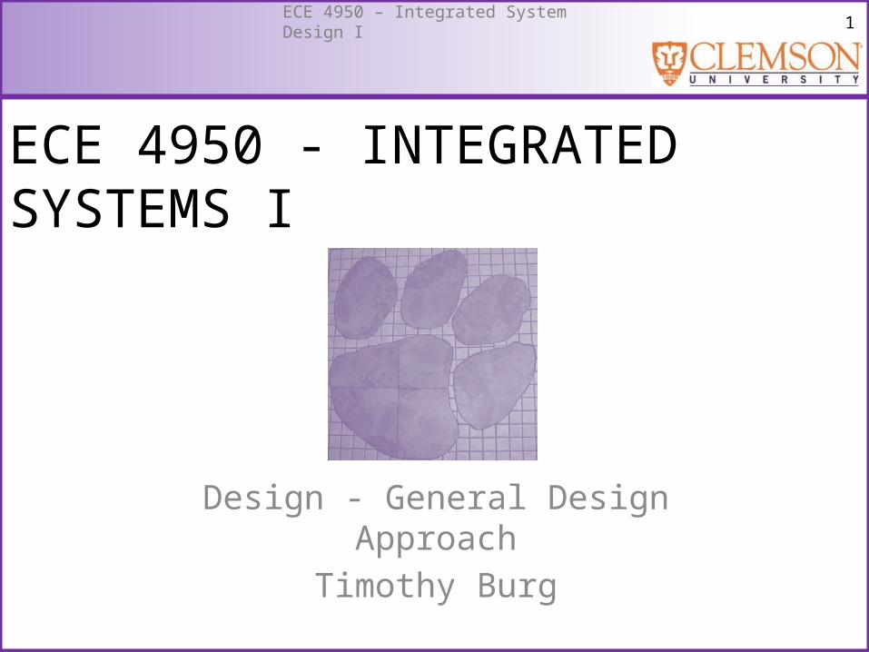
Design Example
IdentifyNeed Research
Specifications
Concepts
Design
Prototype
Testing
Retire
Maintain
Use by Customer(s)
Distribute and Sell
Manufacture
Note: The Design is the end product of the Design Process
6ECE 4950 – Integrated System Design I
Outline: Design Tools
• What is an Electrical Design?– A group of components connected together to
perform a function.• Functional Decomposition
– Top-down approach– Bottom-up approach
7ECE 4950 – Integrated System Design I
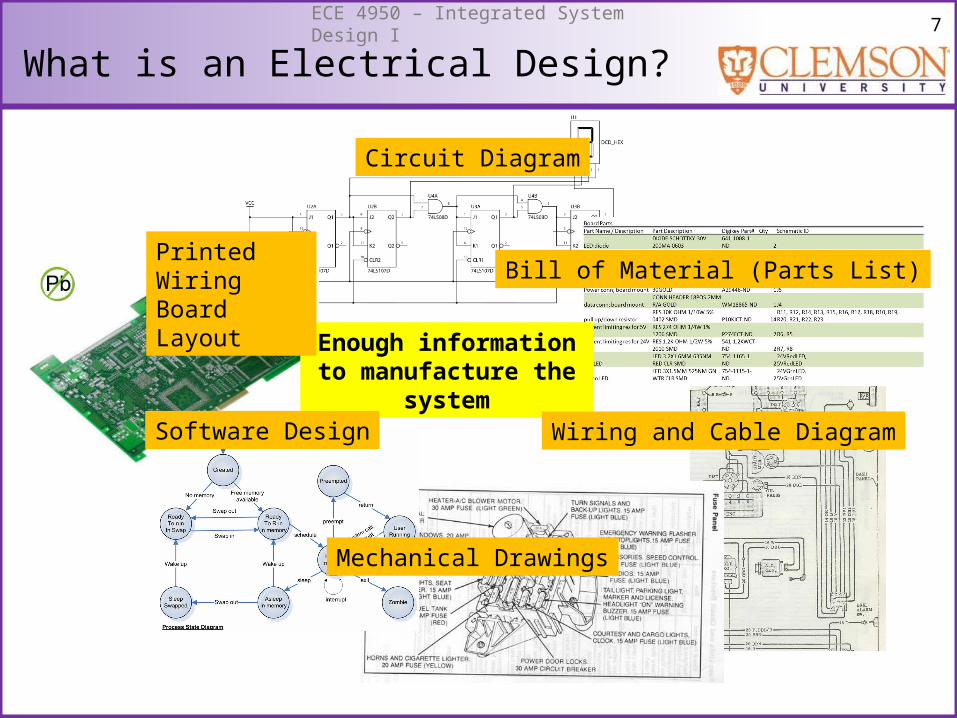
What is an Electrical Design?
Enough information to manufacture the system
Printed Wiring Board Layout Bill of Material (Parts List)
Wiring and Cable DiagramSoftware Design
Circuit Diagram
Mechanical Drawings
8ECE 4950 – Integrated System Design I
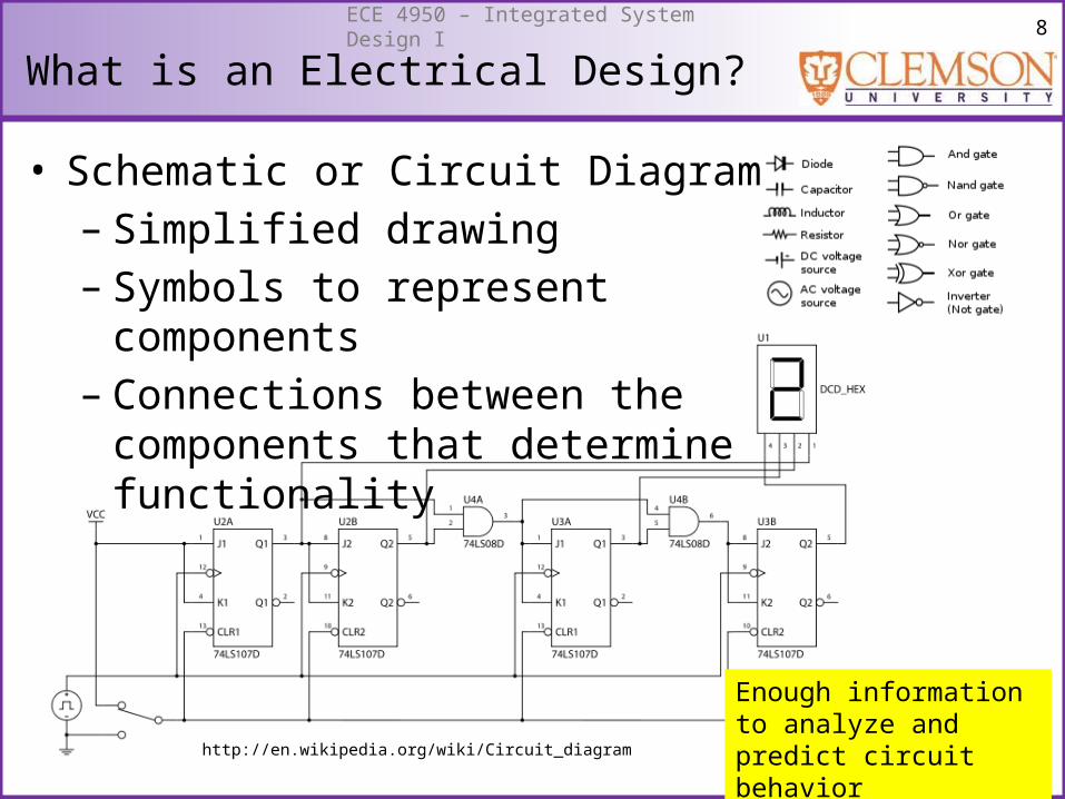
What is an Electrical Design?
• Schematic or Circuit Diagram– Simplified drawing – Symbols to represent components– Connections between the components
that determine functionality
Enough information to analyze and predict circuit behaviorhttp://en.wikipedia.org/wiki/Circuit_diagram
9ECE 4950 – Integrated System Design I
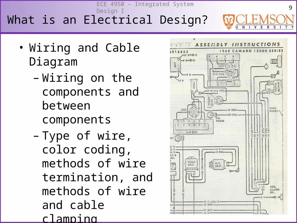
What is an Electrical Design?
• Wiring and Cable Diagram– Wiring on the
components and between components
– Type of wire, color coding, methods of wire termination, and methods of wire and cable clamping
10ECE 4950 – Integrated System Design I
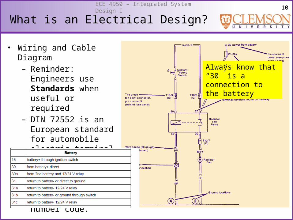
• Wiring and Cable Diagram– Reminder: Engineers use
Standards when useful or required
– DIN 72552 is an European standard for automobile electric terminal numbers, standardizing almost every contact in an automobile with a number code.
Always know that “30” is a connection to the battery
What is an Electrical Design?
11ECE 4950 – Integrated System Design I
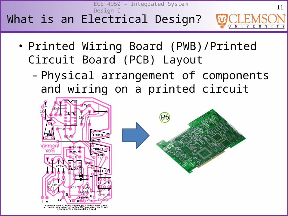
What is an Electrical Design?
• Printed Wiring Board (PWB)/Printed Circuit Board (PCB) Layout– Physical arrangement of components and wiring
on a printed circuit board
12ECE 4950 – Integrated System Design I
What is an Electrical Design?
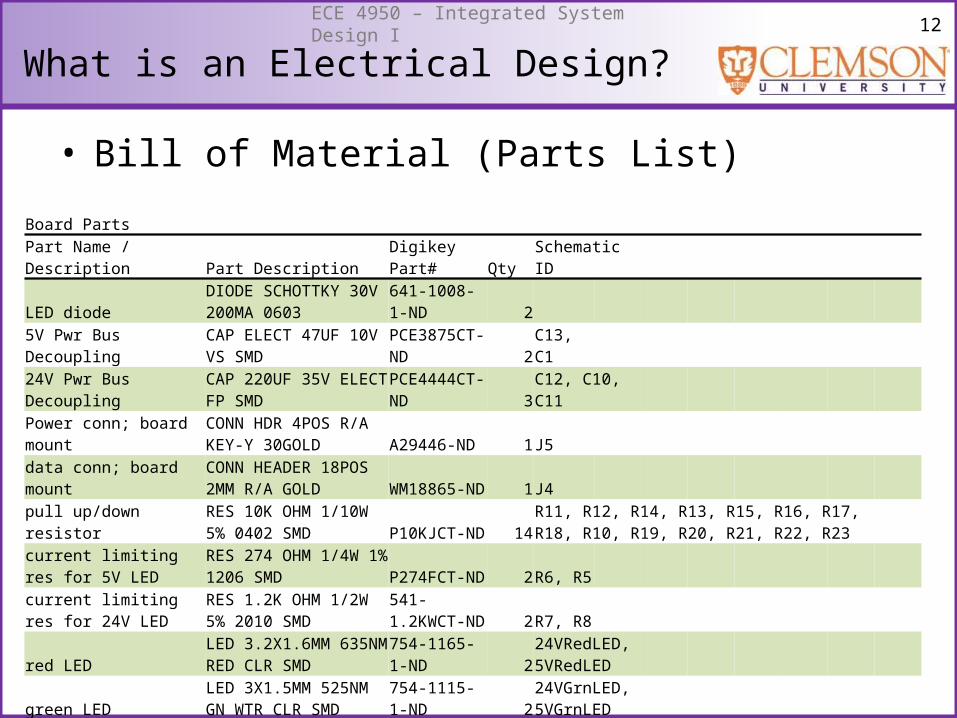
• Bill of Material (Parts List)
Board Parts Part Name / Description Part Description Digikey Part# Qty Schematic ID
LED diodeDIODE SCHOTTKY 30V 200MA 0603
641-1008-1-ND 2
5V Pwr Bus DecouplingCAP ELECT 47UF 10V VS SMD
PCE3875CT-ND 2C13, C1
24V Pwr Bus DecouplingCAP 220UF 35V ELECT FP SMD
PCE4444CT-ND 3C12, C10, C11
Power conn; board mountCONN HDR 4POS R/A KEY-Y 30GOLD A29446-ND 1J5
data conn; board mountCONN HEADER 18POS 2MM R/A GOLD WM18865-ND 1J4
pull up/down resistorRES 10K OHM 1/10W 5% 0402 SMD P10KJCT-ND 14
R11, R12, R14, R13, R15, R16, R17, R18, R10, R19, R20, R21, R22, R23
current limiting res for 5V LED
RES 274 OHM 1/4W 1% 1206 SMD P274FCT-ND 2R6, R5
current limiting res for 24V LED
RES 1.2K OHM 1/2W 5% 2010 SMD
541-1.2KWCT-ND 2R7, R8
red LEDLED 3.2X1.6MM 635NM RED CLR SMD
754-1165-1-ND 2
24VRedLED, 5VRedLED
green LEDLED 3X1.5MM 525NM GN WTR CLR SMD
754-1115-1-ND 2
24VGrnLED, 5VGrnLED
13ECE 4950 – Integrated System Design I
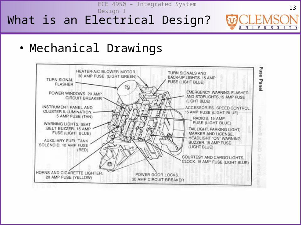
What is an Electrical Design?
• Mechanical Drawings
14ECE 4950 – Integrated System Design I
What is an Electrical Design?
• Software Design– Flowcharts– State transition diagrams– Algorithms
• Cost Estimates
15ECE 4950 – Integrated System Design I
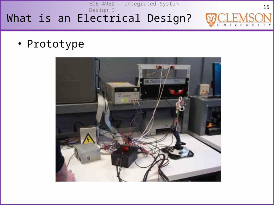
What is an Electrical Design?
• Prototype
16ECE 4950 – Integrated System Design I
What is an Electrical Design?
• The product at the end of this class is an Electrical Design:– Schematic or Circuit Diagram– Wiring and Cable Diagram– Printed Circuit Board (PCB) Layout– Bill of Material (Parts List)– Mechanical Drawings– Software Flowcharts, State transition diagrams,
Algorithms– Cost Estimates– Working Prototype
17ECE 4950 – Integrated System Design I
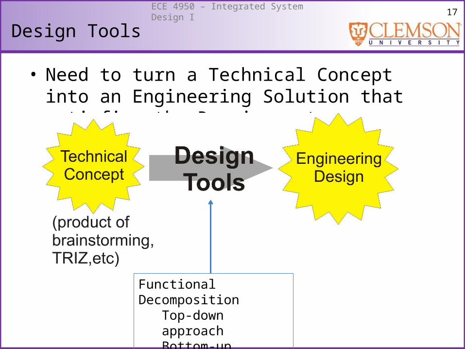
Design Tools
• Need to turn a Technical Concept into an Engineering Solution that satisfies the Requirements
Functional DecompositionTop-down approachBottom-up approach
18ECE 4950 – Integrated System Design I
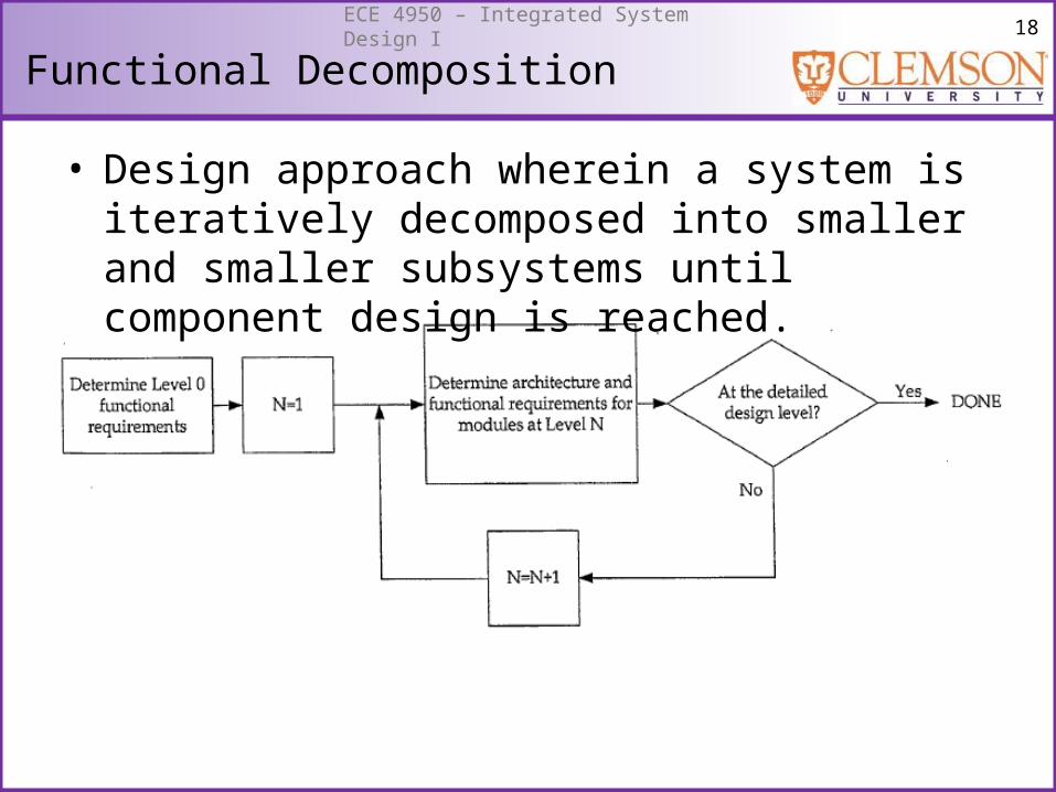
Functional Decomposition
• Design approach wherein a system is iteratively decomposed into smaller and smaller subsystems until component design is reached.
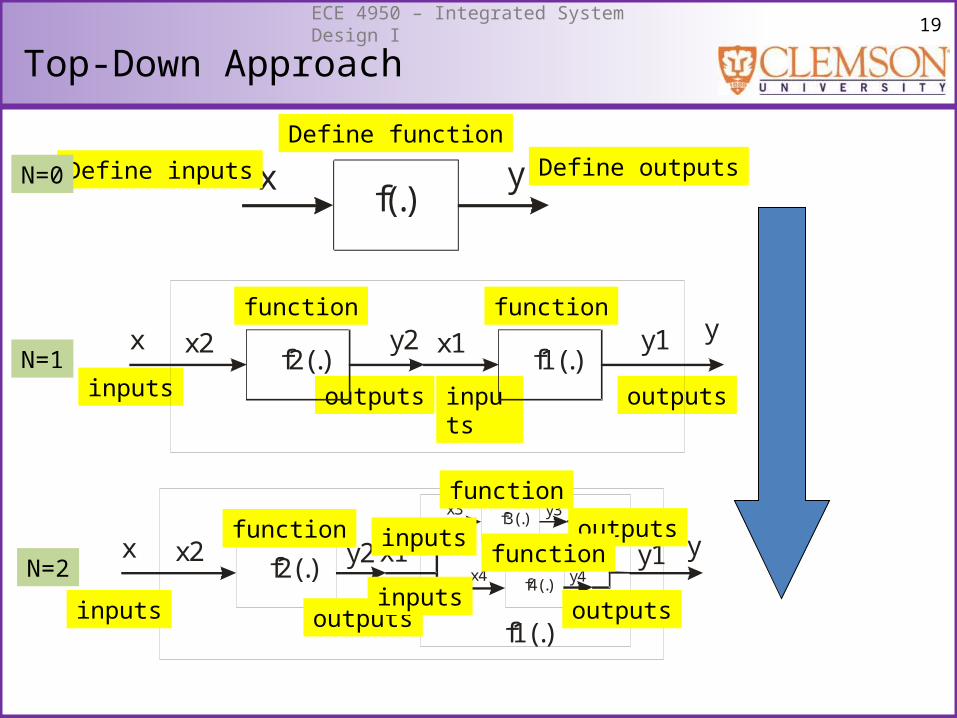
19ECE 4950 – Integrated System Design I
f(.)x y
f2(.)x2 y2
f1(.)x1 y1x y
f2(.)x2 y2
f1(.)
x1 y1x yf3(.)
x3 y3
f4(.)x4 y4
Top-Down Approach
Define inputs Define outputsDefine function
function
outputsoutputs
function
inputs inputs
N=0
N=1
N=2
outputs
function
inputs
outputs
function
inputs
outputs
function
inputs
20ECE 4950 – Integrated System Design I
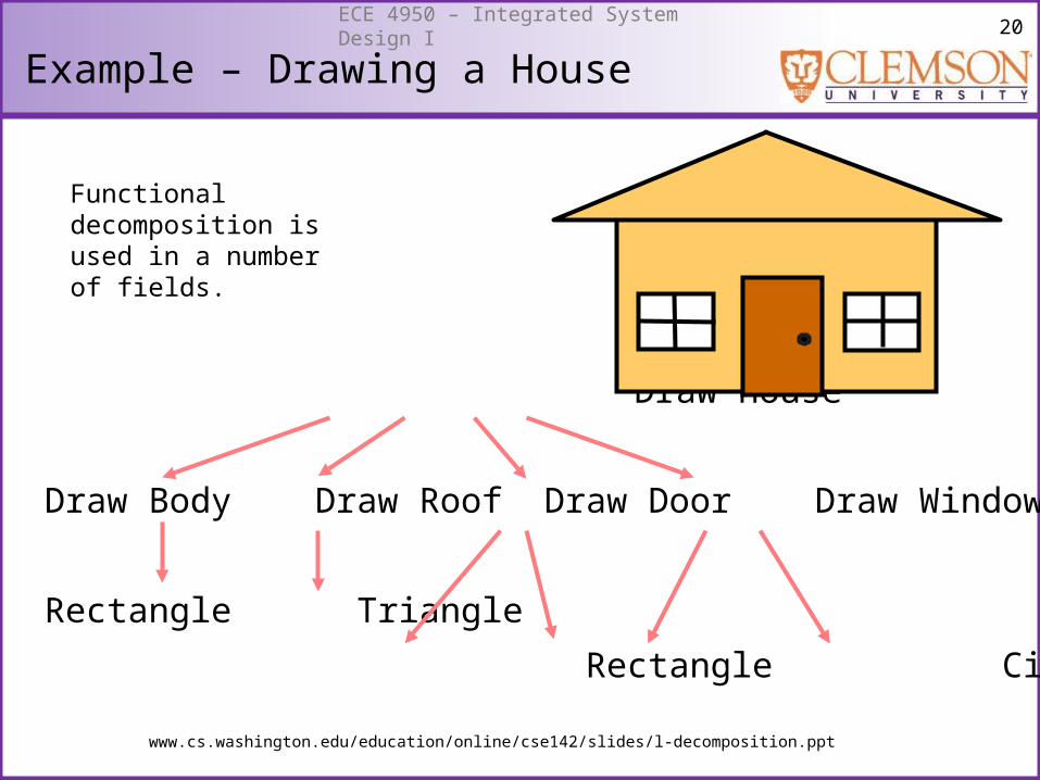
Example – Drawing a House
Draw House
Draw Body Draw Roof Draw Door Draw Window
Rectangle Triangle
Rectangle Circle Rectangle Line
Transformer
Rectifier
Functional decomposition is used in a number of fields.
www.cs.washington.edu/education/online/cse142/slides/l-decomposition.ppt
21ECE 4950 – Integrated System Design I
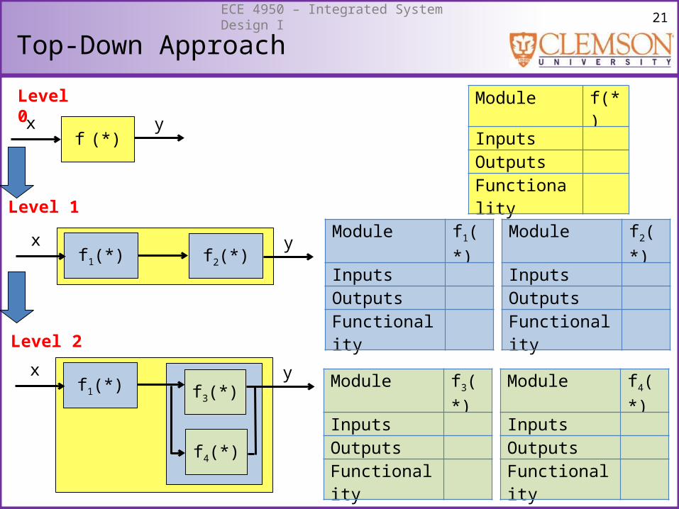
Top-Down Approach
Level 0
Level 1
Level 2
Module f(*)InputsOutputsFunctionality
f1(*) f2(*)
f (*)yx
x yModule f1(*)InputsOutputsFunctionality
Module f2(*)InputsOutputsFunctionality
Module f3(*)InputsOutputsFunctionality
Module f4(*)InputsOutputsFunctionality
f1(*)x y
f3(*)
f4(*)
22ECE 4950 – Integrated System Design I
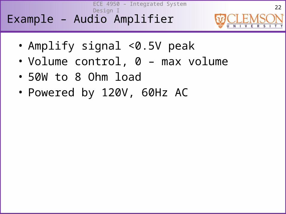
Example – Audio Amplifier
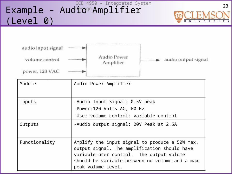
• Amplify signal <0.5V peak• Volume control, 0 – max volume• 50W to 8 Ohm load• Powered by 120V, 60Hz AC
23ECE 4950 – Integrated System Design I
Example – Audio Amplifier (Level 0)
Module Audio Power Amplifier
Inputs -Audio Input Signal: 0.5V peak-Power:120 Volts AC, 60 Hz-User volume control: variable control
Outputs -Audio output signal: 20V Peak at 2.5A
Functionality Amplify the input signal to produce a 50W max. output signal. The amplification should have variable user control. The output volume should be variable between no volume and a max peak volume level.
24ECE 4950 – Integrated System Design I
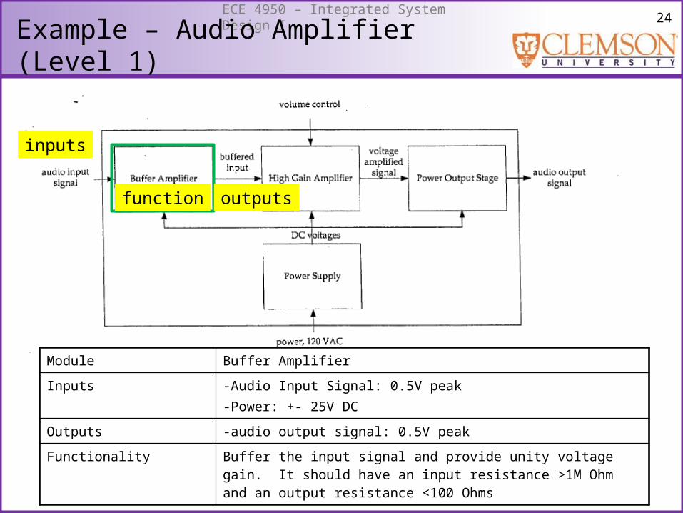
Example – Audio Amplifier (Level 1)
Module Buffer Amplifier
Inputs -Audio Input Signal: 0.5V peak-Power: +- 25V DC
Outputs -audio output signal: 0.5V peak
Functionality Buffer the input signal and provide unity voltage gain. It should have an input resistance >1M Ohm and an output resistance <100 Ohms
outputsfunction
inputs

25ECE 4950 – Integrated System Design I
Example – Audio Amplifier (Level 1)
outputsfunctioninputs
Module High Gain Amplifier
Inputs -Audio Input Signal: 0.5V peak-User volume control:variable control-Power: +/- 25V DC
Outputs -Audio output signal: 20v peak
Functionality Provide an adjustable voltage gain, between 1 and 40. It should have an input resistance >100k Ohms and an output resistance <100 Ohm
inputs
inputs
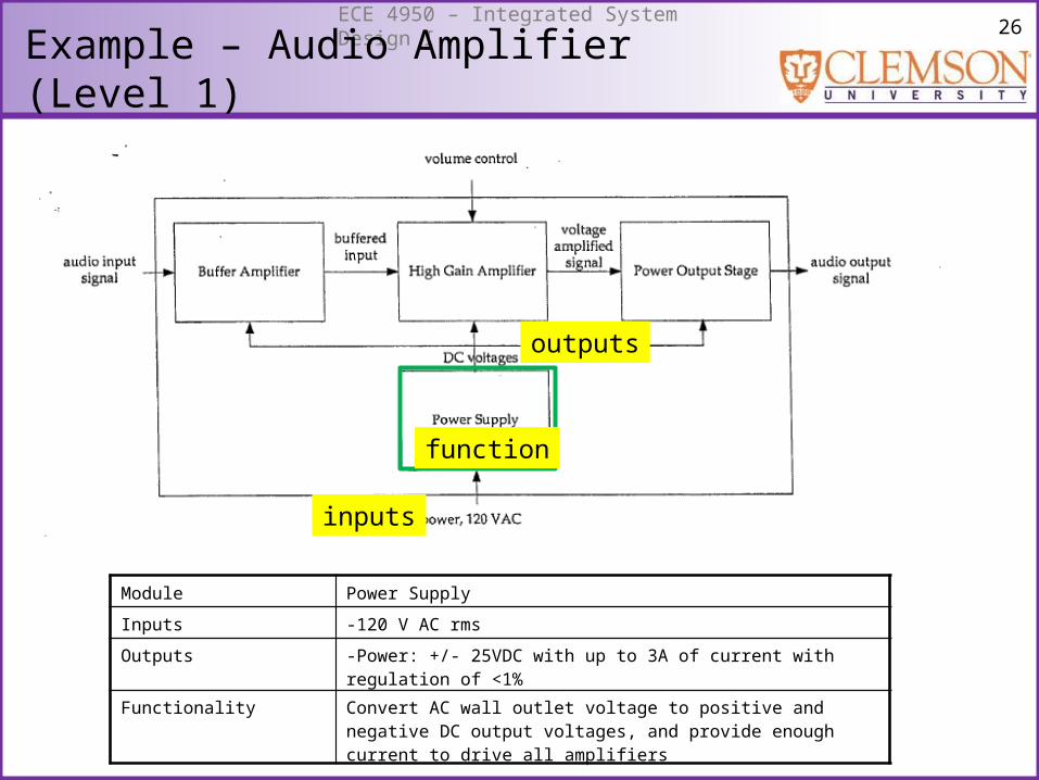
26ECE 4950 – Integrated System Design I
Example – Audio Amplifier (Level 1)
outputs
function
inputs
Module Power Supply
Inputs -120 V AC rms
Outputs -Power: +/- 25VDC with up to 3A of current with regulation of <1%
Functionality Convert AC wall outlet voltage to positive and negative DC output voltages, and provide enough current to drive all amplifiers
27ECE 4950 – Integrated System Design I
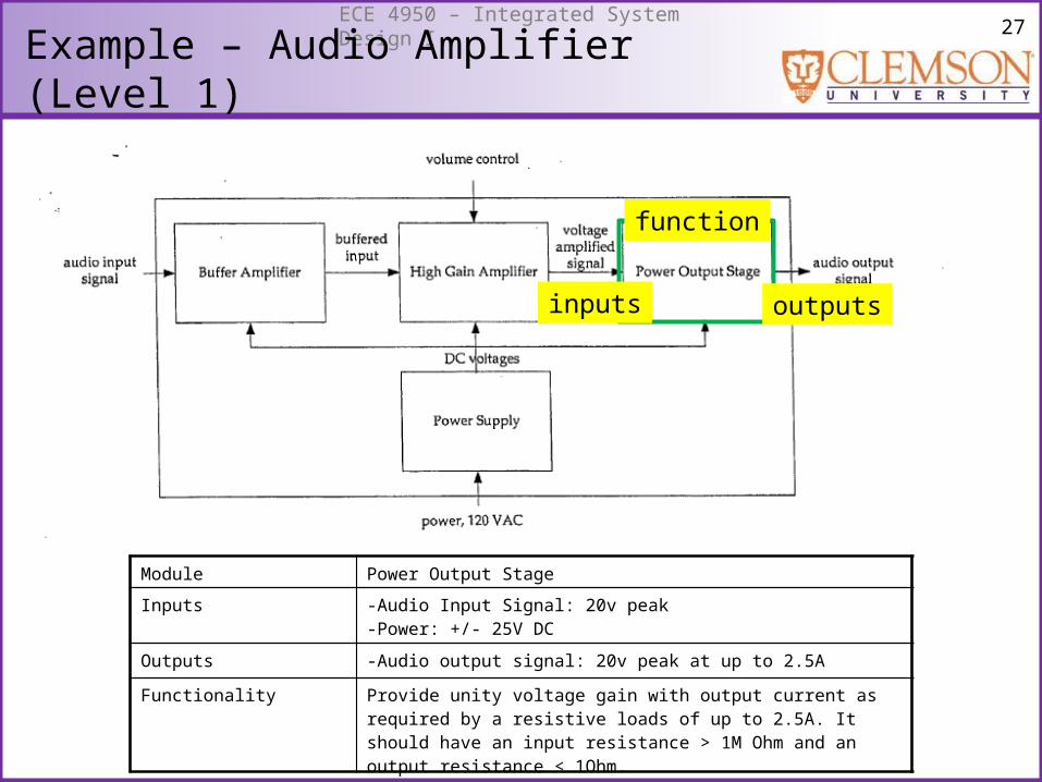
Example – Audio Amplifier (Level 1)
function
inputs
Module Power Output Stage
Inputs -Audio Input Signal: 20v peak-Power: +/- 25V DC
Outputs -Audio output signal: 20v peak at up to 2.5A
Functionality Provide unity voltage gain with output current as required by a resistive loads of up to 2.5A. It should have an input resistance > 1M Ohm and an output resistance < 1Ohm.
outputs
28ECE 4950 – Integrated System Design I
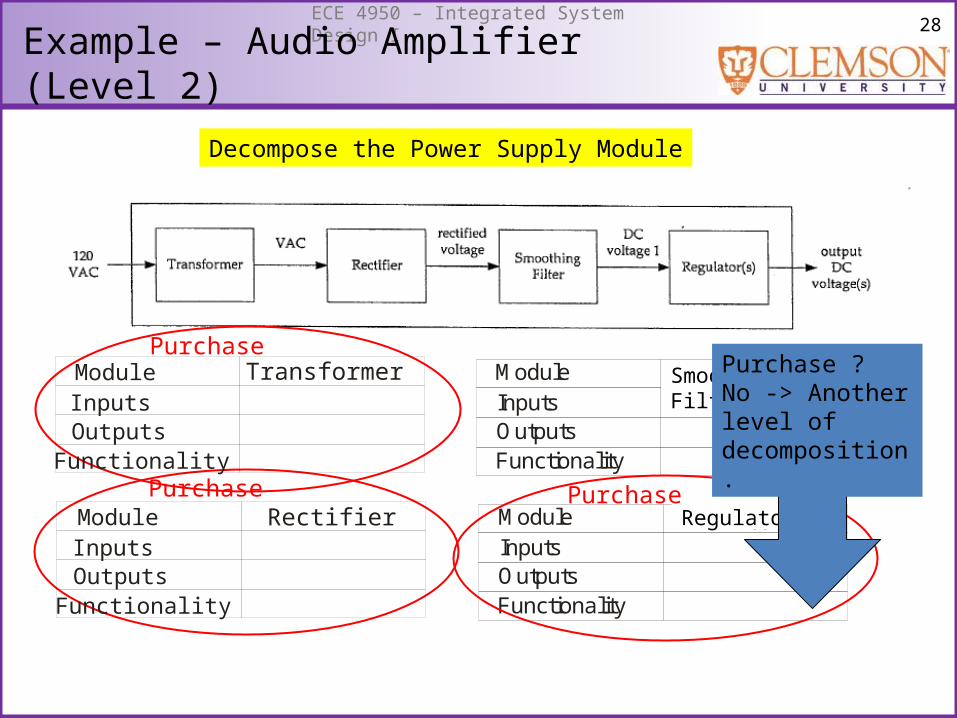
Example – Audio Amplifier (Level 2)
InputsOutputsFunctionality
Module f1(.)
InputsOutputsFunctionality
Module f2(.)
Smoothing Filter
Regulator
Purchase
Purchase Purchase
Purchase ?No -> Another level of decomposition.
InputsOutputsFunctionality
Module Transformer
InputsOutputsFunctionality
Module Rectifier
Decompose the Power Supply Module
29ECE 4950 – Integrated System Design I
Top-Down Approach
• Some components may be constrained.• May want to incorporate a specific device.• Not best for innovation.
30ECE 4950 – Integrated System Design I
f(.)x y
f2(.)x2 y2
f1(.)x1 y1x y
f2(.)x2 y2
f1(.)
x1 y1x yf3(.)
x3 y3
f4(.)x4 y4
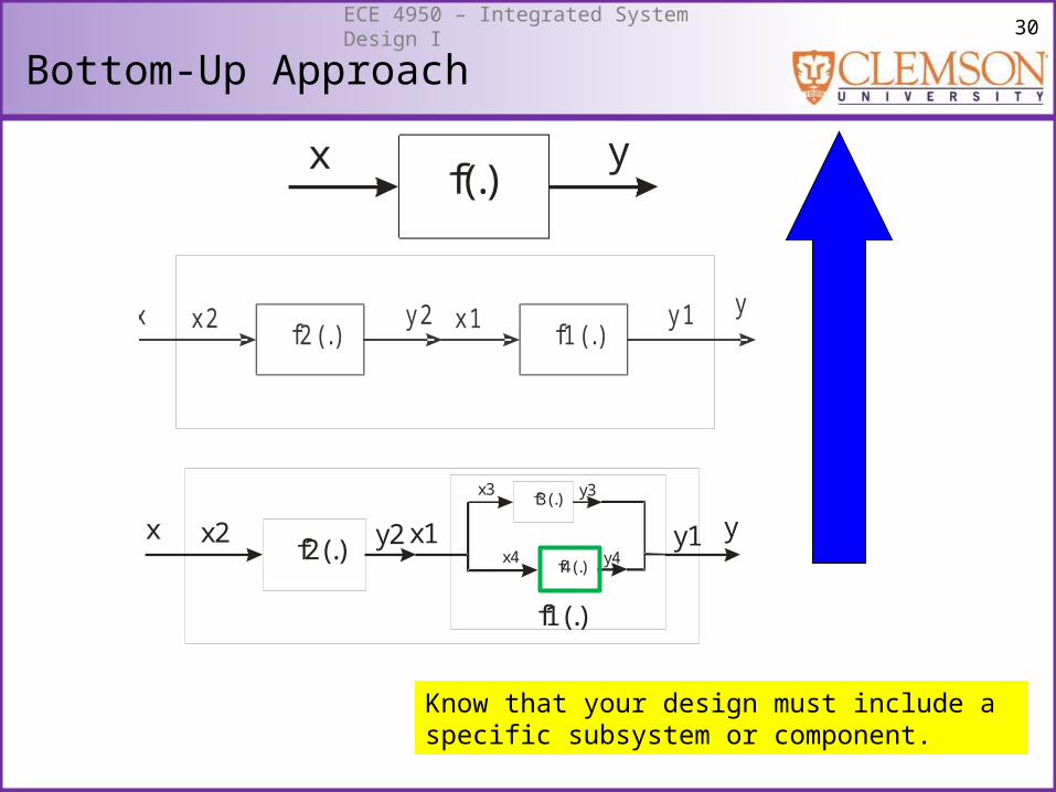
Bottom-Up Approach
Know that your design must include a specific subsystem or component.
31ECE 4950 – Integrated System Design I
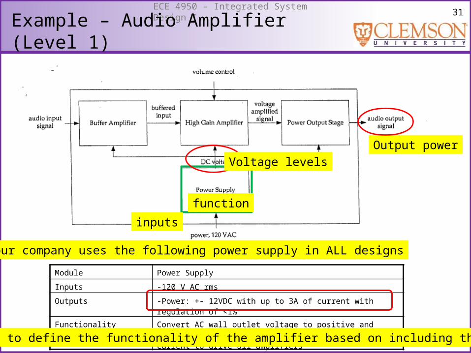
Example – Audio Amplifier (Level 1)
Output power
function
inputs
Module Power Supply
Inputs -120 V AC rms
Outputs -Power: +- 12VDC with up to 3A of current with regulation of <1%
Functionality Convert AC wall outlet voltage to positive and negative DC output voltages, and provide enough current to drive all amplifiers
Your company uses the following power supply in ALL designs
Will have to define the functionality of the amplifier based on including this device
Voltage levels
32ECE 4950 – Integrated System Design I
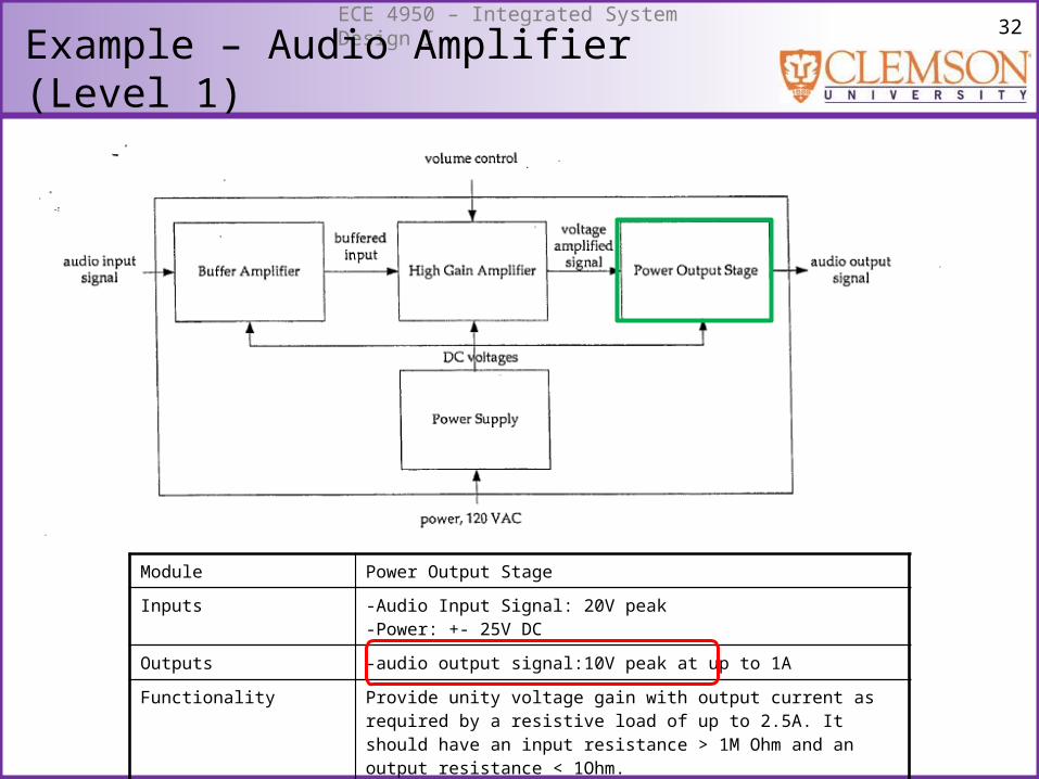
Example – Audio Amplifier (Level 1)
Module Power Output Stage
Inputs -Audio Input Signal: 20V peak-Power: +- 25V DC
Outputs -audio output signal:10V peak at up to 1A
Functionality Provide unity voltage gain with output current as required by a resistive load of up to 2.5A. It should have an input resistance > 1M Ohm and an output resistance < 1Ohm.
33ECE 4950 – Integrated System Design I
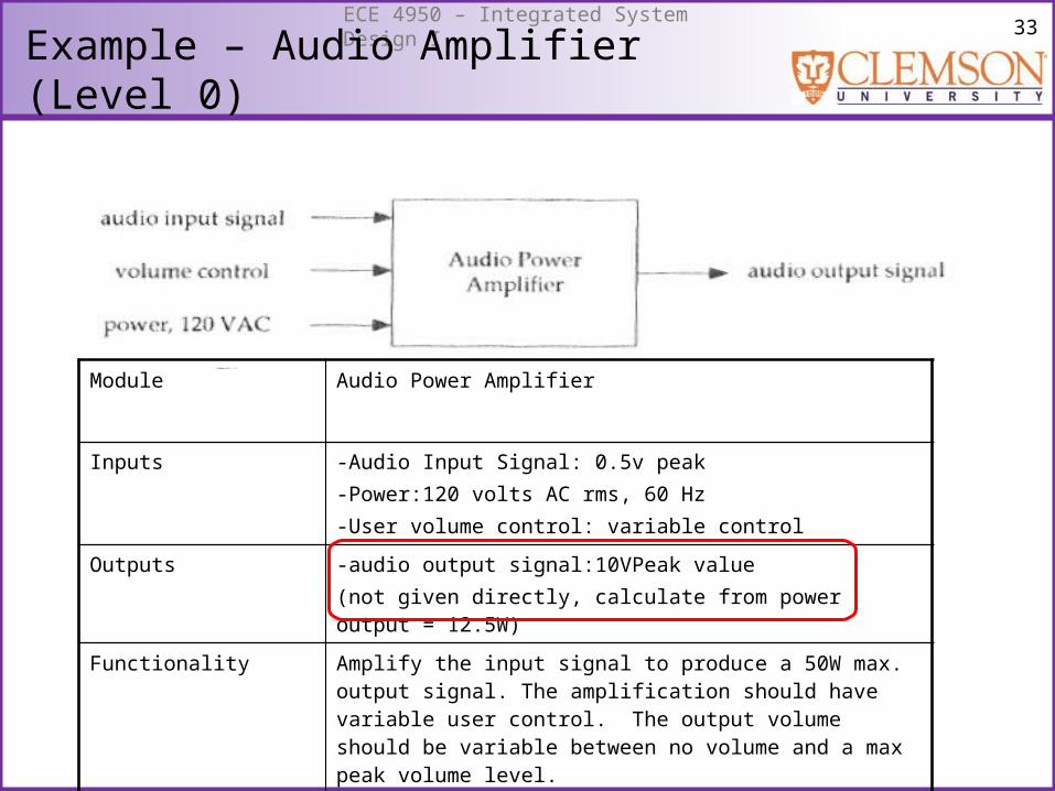
Example – Audio Amplifier (Level 0)
Module Audio Power Amplifier
Inputs -Audio Input Signal: 0.5v peak-Power:120 volts AC rms, 60 Hz-User volume control: variable control
Outputs -audio output signal:10VPeak value(not given directly, calculate from power output = 12.5W)
Functionality Amplify the input signal to produce a 50W max. output signal. The amplification should have variable user control. The output volume should be variable between no volume and a max peak volume level.

34ECE 4950 – Integrated System Design I
Bottom-Up Approach
• Facilitates use of standard or reusable components.• Lego approach – I have all of these pieces, what can I
build with the components I have?
35ECE 4950 – Integrated System Design I
Top-Down vs. Bottom-Up
• In reality both approaches are used iteratively.
36ECE 4950 – Integrated System Design I
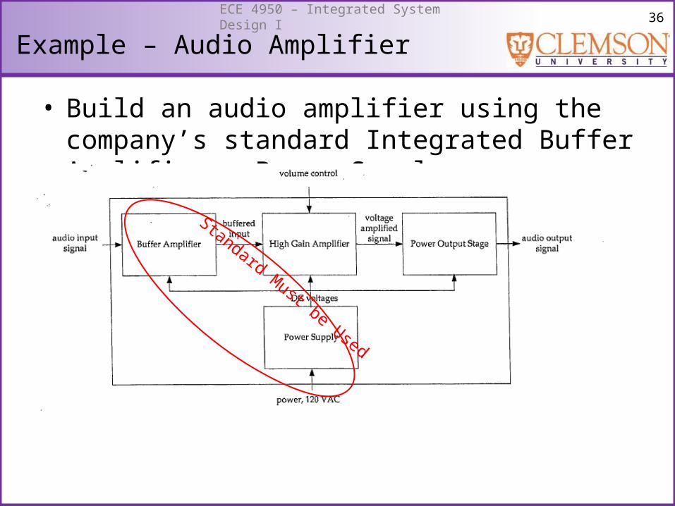
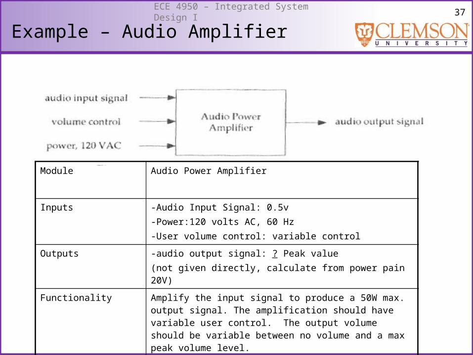
Example – Audio Amplifier
• Build an audio amplifier using the company’s standard Integrated Buffer Amplifier + Power Supply.
Standard Must be Used
37ECE 4950 – Integrated System Design I
Example – Audio Amplifier
Module Audio Power Amplifier
Inputs -Audio Input Signal: 0.5v-Power:120 volts AC, 60 Hz-User volume control: variable control
Outputs -audio output signal: ? Peak value(not given directly, calculate from power pain 20V)
Functionality Amplify the input signal to produce a 50W max. output signal. The amplification should have variable user control. The output volume should be variable between no volume and a max peak volume level.
38ECE 4950 – Integrated System Design I
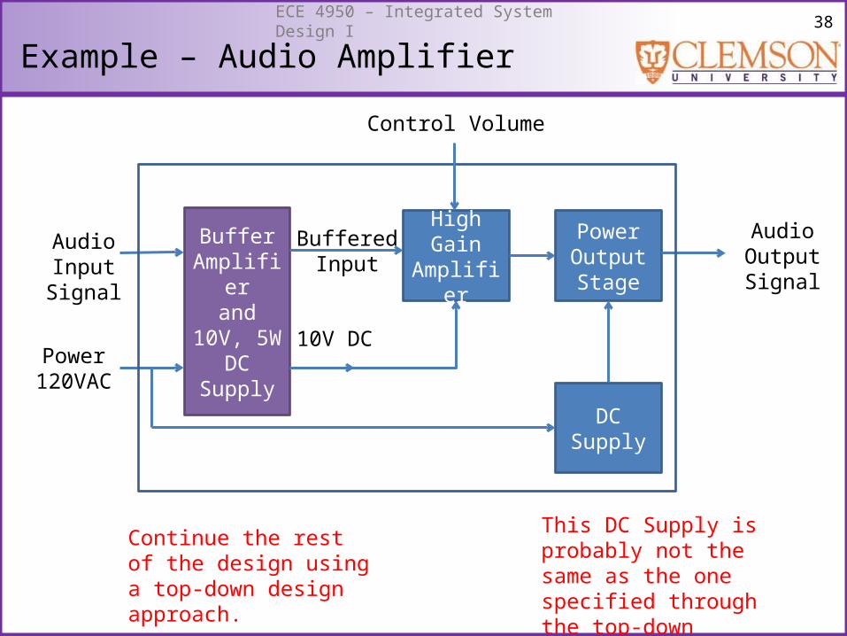
Example – Audio Amplifier
BufferAmplifier
and10V, 5W
DC Supply
High GainAmplifier
Power OutputStage
AudioInputSignal
Power120VAC
BufferedInput
10V DC
DC Supply
Control Volume
AudioOutputSignal
This DC Supply is probably not the same as the one specified through the top-down approach.
Continue the rest of the design using a top-down design approach.
39ECE 4950 – Integrated System Design I
Summary
• Many tools available for organizing your design.• Size of the project will determine what tools are
useful.• Key point: Before starting a design project identify
the tools that are appropriate for your project.