1 DREDGED MATERIAL MANAGEMENT PLAN
12
FREEPORT HARBOR CHANNEL IMPROVEMENT PROJECT 50-YEAR DREDGED MATERIAL MANAGEMENT PLAN HDR 10026951 1 December, 2017 (Rev K) 1 DREDGED MATERIAL MANAGEMENT PLAN 1.1 PURPOSE The goal of this Dredged Material Management Plan (DMMP) is to develop a placement plan that will accommodate the placement of new work and maintenance dredged material over 50 years associated with the Freeport Harbor Channel Improvement Project General Revaluation Report (FHCIP GRR). Dredged material management planning for all Federal harbor projects is conducted by USACE to ensure that dredging activities are performed in an environmentally acceptable manner, use sound engineering techniques, are economically justified, and to ensure that long-term placement facilities are available. Ultimately, the DMMP identifies specific measures necessary to manage the volume of material likely to be dredged within the FHCIP project over the 50-year period of analysis included in the GRR. This DMMP considers maintenance and new work dredging volume associated with the FHCIP GRR including: Existing channel to 46 feet MLLW; Proposed Turning Notch, Channel Widening, and Bend Easing to 46 feet MLLW. All new work dredging has an advanced maintenance depth of 2 feet and an allowable overdepth of 1 foot. 1.2 PLACEMENT AREAS Dredged material placement areas near Freeport Harbor are shown in Figure 1. The Maintenance Ocean Dredged Material Disposal Site (ODMDS) and Placement Area 1 (PA1) are being considered as potential disposal sites in this DMMP. With the recommendation that all maintenance material be placed in the ODMDS, the overall volume of sediment requiring upland confined storage drops dramatically. This DMMP considers the placement area requirements specifically for the GRR project features and was developed in a manner that avoids potential conflicts with the placement area needs outlined in the DMMP previously developed as part of the 2012 FHCIP Feasibility Study (USACE, 2012b). 1.2.1 MAINTENANCE OCEAN DREDGED MATERIAL DISPOSAL SITE (ODMDS) The Maintenance ODMDS is located in the Gulf of Mexico, approximately 2.5 miles southwest from the mouth of the Jetty Channel and approximately 3 miles from shore. The site is located in a dispersive offshore environment with approximately 1,129 acres of bottom area. Due to its dispersive nature, the site can be assumed to have unlimited capacity. Coordinates of control points for the Maintenance ODMDS are presented in Table 1. The maintenance ODMDS previously had restrictions that limited placement to material from certain reaches of the channel. However, currently, 40 CFR 228.15 allows material from the entire channel to be placed offshore in the ODMDS.
Transcript of 1 DREDGED MATERIAL MANAGEMENT PLAN
FREEPORT HARBOR CHANNEL IMPROVEMENT PROJECT
50-YEAR DREDGED MATERIAL MANAGEMENT PLAN
HDR 10026951 1 December, 2017 (Rev K)
1 DREDGED MATERIAL MANAGEMENT PLAN
1.1 PURPOSE
The goal of this Dredged Material Management Plan (DMMP) is to develop a placement plan that will
accommodate the placement of new work and maintenance dredged material over 50 years associated
with the Freeport Harbor Channel Improvement Project General Revaluation Report (FHCIP GRR).
Dredged material management planning for all Federal harbor projects is conducted by USACE to ensure
that dredging activities are performed in an environmentally acceptable manner, use sound engineering
techniques, are economically justified, and to ensure that long-term placement facilities are available.
Ultimately, the DMMP identifies specific measures necessary to manage the volume of material likely to
be dredged within the FHCIP project over the 50-year period of analysis included in the GRR.
This DMMP considers maintenance and new work dredging volume associated with the FHCIP GRR
including: Existing channel to 46 feet MLLW; Proposed Turning Notch, Channel Widening, and Bend
Easing to 46 feet MLLW. All new work dredging has an advanced maintenance depth of 2 feet and an
allowable overdepth of 1 foot.
1.2 PLACEMENT AREAS
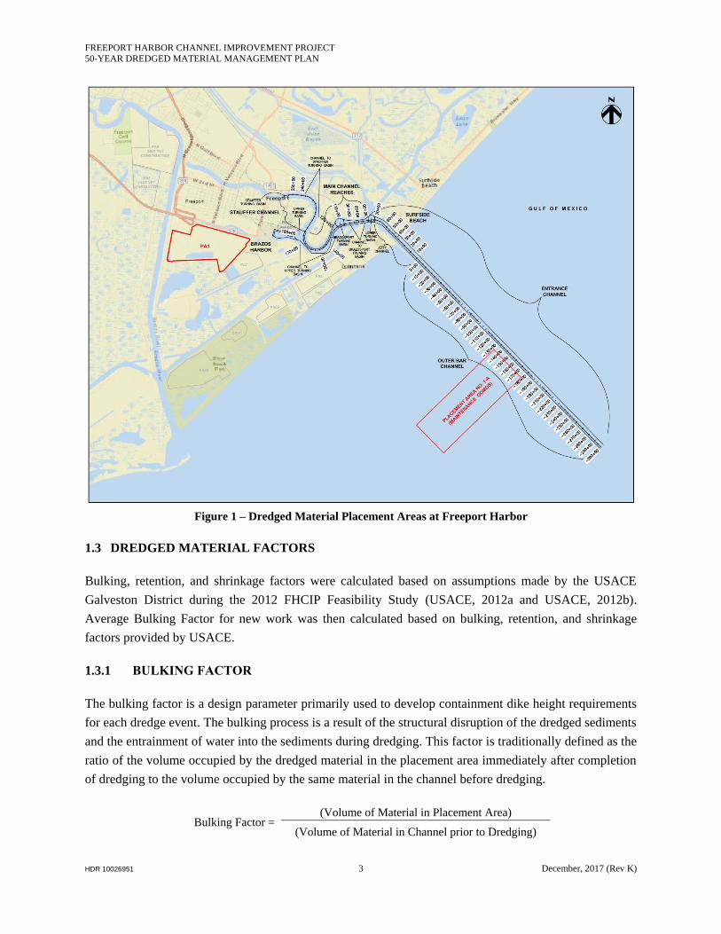
Dredged material placement areas near Freeport Harbor are shown in Figure 1. The Maintenance Ocean
Dredged Material Disposal Site (ODMDS) and Placement Area 1 (PA1) are being considered as potential
disposal sites in this DMMP. With the recommendation that all maintenance material be placed in the
ODMDS, the overall volume of sediment requiring upland confined storage drops dramatically.
This DMMP considers the placement area requirements specifically for the GRR project features and was
developed in a manner that avoids potential conflicts with the placement area needs outlined in the
DMMP previously developed as part of the 2012 FHCIP Feasibility Study (USACE, 2012b).
1.2.1 MAINTENANCE OCEAN DREDGED MATERIAL DISPOSAL SITE (ODMDS)
The Maintenance ODMDS is located in the Gulf of Mexico, approximately 2.5 miles southwest from the
mouth of the Jetty Channel and approximately 3 miles from shore. The site is located in a dispersive
offshore environment with approximately 1,129 acres of bottom area. Due to its dispersive nature, the site
can be assumed to have unlimited capacity. Coordinates of control points for the Maintenance ODMDS
are presented in Table 1. The maintenance ODMDS previously had restrictions that limited placement to
material from certain reaches of the channel. However, currently, 40 CFR 228.15 allows material from
the entire channel to be placed offshore in the ODMDS.
FREEPORT HARBOR CHANNEL IMPROVEMENT PROJECT
50-YEAR DREDGED MATERIAL MANAGEMENT PLAN
HDR 10026951 2 December, 2017 (Rev K)
Table 1 – Maintenance ODMDS Control Points
Control Point
Number
Cartesian Coordinates
(NAD83, Texas South Central, US Survey Feet)
Easting Nothing
1 3,163,694 13,530,298
2 3,166,836 13,527,077
3 3,157,888 13,518,349
4 3,154,745 13,521,570
1.2.2 PLACEMENT AREA 1
PA1 is located in Freeport roughly 0.5 mile south of State Highway 36 and approximately 1,000 feet east
of the Brazos River Diversion Channel (USACE 2012a). The PA is approximately 320 acres, with a
perimeter length of approximately 20,310 linear feet. Existing ground elevation is approximately 21 feet
NAVD (North American Vertical Datum of 1988) with a dike height of 25 feet NAVD. While the
existing capacity of PA1 is approximately 0.8 mcy, the PA is estimated to provide up to 3.4 mcy of
capacity if the dikes are raised to 31.5 feet NAVD. This DMMP proposes a dike elevation increase to
31.5 feet NAVD for PA1. This height includes 3 feet for ponding and freeboard above the targeted bulk
dredged fill height. Dike raises within PA 1 have historically borrowed material from the interior of the
placement area. There is considerable material within the site available for future raises particularly near
the discharge site on the eastern section of the placement area. The dikes are scheduled to be raised in
support of the Stauffer channel dredging, which is a new work project. This material will be available for
future dike raises.
FREEPORT HARBOR CHANNEL IMPROVEMENT PROJECT
50-YEAR DREDGED MATERIAL MANAGEMENT PLAN
HDR 10026951 3 December, 2017 (Rev K)
Figure 1 – Dredged Material Placement Areas at Freeport Harbor
1.3 DREDGED MATERIAL FACTORS
Bulking, retention, and shrinkage factors were calculated based on assumptions made by the USACE
Galveston District during the 2012 FHCIP Feasibility Study (USACE, 2012a and USACE, 2012b).
Average Bulking Factor for new work was then calculated based on bulking, retention, and shrinkage
factors provided by USACE.
1.3.1 BULKING FACTOR
The bulking factor is a design parameter primarily used to develop containment dike height requirements
for each dredge event. The bulking process is a result of the structural disruption of the dredged sediments
and the entrainment of water into the sediments during dredging. This factor is traditionally defined as the
ratio of the volume occupied by the dredged material in the placement area immediately after completion
of dredging to the volume occupied by the same material in the channel before dredging.
Bulking Factor = (Volume of Material in Placement Area)
(Volume of Material in Channel prior to Dredging)
FREEPORT HARBOR CHANNEL IMPROVEMENT PROJECT
50-YEAR DREDGED MATERIAL MANAGEMENT PLAN
HDR 10026951 4 December, 2017 (Rev K)
The amount of bulking varies with the type of sediments and the method of dredging (mechanical or
hydraulic). Other factors that affect bulking include size of dredge, horsepower, and residence time in the
pipeline. For this project, dredging will primarily be conducted hydraulically. The new work dredging for
this project will consist of about 80 to 90 percent clays (of primarily stiff consistency with some traces of
silts or clayey silts), and about 10 to 20 percent sands of various densities, based on available boring data
from the Upper Turning Basin on out to sea.
Development of containment dike height requirements on this project was based on a bulking factor of
about 1.3 for maintenance material and about 2 for the portion of new work material anticipated to go into
a slurry state before final discharge at the disposal sites. The remaining portion of new work material that
will come out of the dredge pipe in the form of solid clay fragments (informally referred to as “clay
balls”) or segregate from the dredge mixture soon after discharge (such as sands) is anticipated to remain
fairly close to the original density from the channel.
1.3.2 RETENTION FACTOR
For calculations and quantities produced on this project, the definition adopted for the term “retention
factor” is the fraction of new work material from the channel that, when dredged to the site, retains a
degree of consistency from the original in situ state necessary for use as fill materials for hydraulic
containment dike and containment dike foundation construction or future borrow for future mechanical
containment dike construction; and that, when pumped to the site, tends to accumulate or stack within the
general vicinity of the end of the dredge pipe
Retention Factor = (Volume of Dredged Material Suitable for Containment Dike Fill Material)
(Annual Dredging Quantity)
Variables that can influence this factor include original in situ material properties and consistencies, size
of dredge, type and control of cutter head, horsepower, and pump distance. For feasibility level, a
retention factor of about 0.5 was assumed for this project.
1.3.3 SHRINKAGE FACTOR
The shrinkage factor is a design parameter used to evaluate the long-term storage capacity of a PA for use
in developing the DMMP. It is defined as the ratio of the long-term volume occupied by a certain quantity
of dredged material in a PA, to the volume it occupied in the channel prior to dredging. Generally, this
parameter is associated with maintenance material, but may also be associated with new work material.
Shrinkage Factor = (Long-term Volume in Disposal Area)
(Volume in Channel Prior to Dredging)
Items that affect the shrinkage include the soil composition, pan of evaporation rate, consolidation,
desiccation, climatological conditions, drainage efficiency or dewatering measures implemented, and
FREEPORT HARBOR CHANNEL IMPROVEMENT PROJECT
50-YEAR DREDGED MATERIAL MANAGEMENT PLAN
HDR 10026951 5 December, 2017 (Rev K)
dredging schedule of maintenance material placed at the sites. Determination of a precise shrinkage factor
for a placement area can be a complex task and include modeling the consolidation and desiccation
shrinkage based on laboratory test data, climatological data, drainage characteristics, and operational
characteristics. For feasibility level, the development of the long-term storage capacity and containment
dike height requirements on this project was based on a shrinkage factor of about 0.65 for maintenance
material.
1.3.4 NEW WORK AVERAGE BULKING FACTOR
Assuming 85% clay and 15% sand and given the retention factor of 0.5 and the bulking factor of 2.0, it is
expected that 50% of the clay material would expand by a factor of 2.0 while the rest of the clay and all
the sand would retain their in situ density. This leads to a new work average bulking factor of 1.425 for
placement. In other words, for the purpose of placement calculations, it is expected that the new work
material would expand by a factor of 1.425.
For long term calculations, when the shrinkage factor of 0.65 is applied to the bulked clay material, it
leads to a new work average bulking factor of 1.13. In other words. For the purpose of long term PA
capacity calculations, it is expected that the new work material would expand by a factor of 1.13.
1.4 DREDGED MATERIAL CLASSIFICATION
New work dredged material to be removed for the FHCIP GRR is assumed to have consistent
composition with the classification provided in the 2012 FHCIP Feasibility Study. The new work is
expected to consist of 10-20 percent sand and 80-90 percent clay. Due to lack of boring data, soil
classification was not performed for the new work on the Stauffer Channel.
1.5 DREDGED MATERIAL QUANTITIES
The quantity of new work material for the proposed GRR widening at Freeport Harbor to achieve
Alternative 2 at the Freeport Harbor Channel is approximately 1.734 mcy, as classified in The quantities
were determined using the average end area method.
The quantity of maintenance material to be removed over the 50-year GRR 46 ft project life is estimated
to be approximately 15.3 mcy, as presented in Table 3. These quantities were determined by reviewing
maintenance dredging contracts within the project area for the last 20 years and applying an incremental
increase in dredging due to the widened and deepened channel (HDR, 2016). This quantity includes
120,000 cy of maintenance dredged material estimated to be removed from the Lower Stauffer Channel.
Lacking historical dredging records within the Lower Stauffer Channel, sedimentation rates (within the
Lower Stauffer Channel) were estimated by reviewing maintenance dredging requirements within the
adjacent portion of the Freeport Harbor main channel.

FREEPORT HARBOR CHANNEL IMPROVEMENT PROJECT
50-YEAR DREDGED MATERIAL MANAGEMENT PLAN
HDR 10026951 6 December, 2017 (Rev K)
1.6 PLACEMENT PLANS
Placement plans are required to ensure that there is sufficient capacity within the designated placement
areas necessary to contain both the new work dredged materials from the widening and deepening of the
channel as well as future maintenance material from the repeated dredging of the channel to maintain
navigable project depths over a 50-year period.
1.6.1 NEW WORK DREDGED MATERIAL PLACEMENT PLAN
All dredged material for GRR new work, totaling approximately 1.734 mcy, is designated for placement
at PA1 by transfer through pipeline. For Placement Area capacity assessment purposes, this DMMP also
considers an additional 270,000 cy of WIK dredging that is expected to emerge from new work at the
Lower Stauffer Channel as part of the FHCIP. The Lower Stauffer Channel will be improved based on the
WRRDA 2014 authorization (WRRDA, 2014).
To consider the material expansion for placement purposes, a combined average bulking factor of 1.425
was calculated and applied based on the information in Section 1.3, resulting in a bulked volume of
approximately 2.47 mcy. Note that for long term Placement Area assessments, the average bulking factor
was calculated as 1.13. Table 2 contains the placement plan for new work dredged material.
Table 2 – Placement Plan for New Work Dredged Material
Reach Stations
In-place
Vol. (cy)
Avg. Bulking
Factor
Expanded
Vol. (cy)
Disposal
Site From To
Bend Easing 147+00 159+85 1,478,000 1.425 2,106,150 PA1
Turning Notch 175+77 181+41 106,000 1.425 151,050 PA1
Channel Widening 142+28 184+20 150,000 1.425 213,750 PA1
Total New GRR Work Dredged Material 142+28 198+50 1,734,000 1.425 2,470,950 PA1
Lower Stauffer Channel (WIK)* 184+20 198+50 270,000 1.425 384,750 PA1
* Not part of the GRR, provided for PA capacity assessment purposes only.
1.6.2 50-YEAR MAINTENANCE PLACEMENT PLAN
After the completion of new work dredging for the Freeport GRR and the Lower Stauffer Channel, the
project will require periodic maintenance dredging to retain navigability. It is estimated that the Freeport
Harbor Channel (Stations 71+52 to 184+20) will receive an annual shoaling volume of approximately
315,000 cy (HDR, 2016) pursuant to the implementation of the GRR features. Additionally, it is
estimated that the Lower Stauffer Channel will receive an annual shoaling rate of approximately 2,500 cy.
This DMMP is based on maintenance dredging in 3-year cycles for reaches below Station 184+20 and 12-
year cycles for reaches above Station 184+20., resulting in a total dredged volume of approximately 15.3
mcy. All maintenance dredged volume is designated for placement at the Maintenance ODMDS. In

FREEPORT HARBOR CHANNEL IMPROVEMENT PROJECT
50-YEAR DREDGED MATERIAL MANAGEMENT PLAN
HDR 10026951 7 December, 2017 (Rev K)
addition, there will be some residual capacity available at PA1 which is planned to be used for minor
occasional maintenance dredging requirements. Table 3 contains the 50-year placement plan for the
maintenance dredged material.
Table 3 – 50-Year Placement Plan for Maintenance Dredged Material
Reach
Stations Annual
Vol. (cy)
Cycle
Length
(year)
Vol. per
Cycle
(cy)
No. of
Cycles
Total Vol.
(cy) Disposal Site
From To
Bend Easing 147+00 159+85 30,900 3 92,700 16 1,483,200 Maintenance
ODMDS
Turning Notch 175+77 181+41 10,800 3 32,400 16 518,400 Maintenance
ODMDS
Channel Widening 142+28 184+20 12,900 3 38,700 16 619,200 Maintenance
ODMDS
Existing Harbor Channel 71+52 184+20 261,000 3 783,000 16 12,528,000 Maintenance
ODMDS
Lower Stauffer Channel 184+20 198+50 2,500 12 30,000 4 120,000 Maintenance
ODMDS
Total Maintenance Dredged Material 71+52 198+50 318,100 VARIES 15,268,800 Maintenance
ODMDS
1.7 BENEFICIAL USE OPPORTUNITIES
A comparison of potential Beneficial Use (BU) opportunities to upland confined placement has been
performed and can be found in Attachment 8 of FHCIP GRR Engineering Appendix. Total costs have not
been estimated, rather a comparison of the work required for each has been conducted.
The current GRR plan contains approximately 1.7 mcy of new work material. Potentially viable options
in the project vicinity for BU could include either beach nourishment or marsh nourishment. Due to low
sand content of the dredged material, only marsh nourishment projects appeared viable. A potential BU
site was identified and shown in on northeast of the project feature at the intersection of Texas State
Highway 332 and Casko Road. The site was selected based on its proximity to the dredge site, no data
(geotechnical, biological or survey) information has been collected and very limited real estate
coordination has been conducted for the site. Amid the unknown existing elevation within the BU site, an
average fill height of 3 feet was assumed. Based on this fill height the potential BU site can contain
roughly 0.7 mcy of dredged material. The BU site does not have sufficient area to hold all 1.7 mcy of new
work material; therefore, the remaining 1.0 mcy of new work material needs to be placed at PA1. A
natural meandering channel, currently passes through the BU site. In order to retain the existing channel,
the BU site was split in to two (2) parcels. A map of the potential BU site is presented in Figure 2
FREEPORT HARBOR CHANNEL IMPROVEMENT PROJECT
50-YEAR DREDGED MATERIAL MANAGEMENT PLAN
HDR 10026951 8 December, 2017 (Rev K)
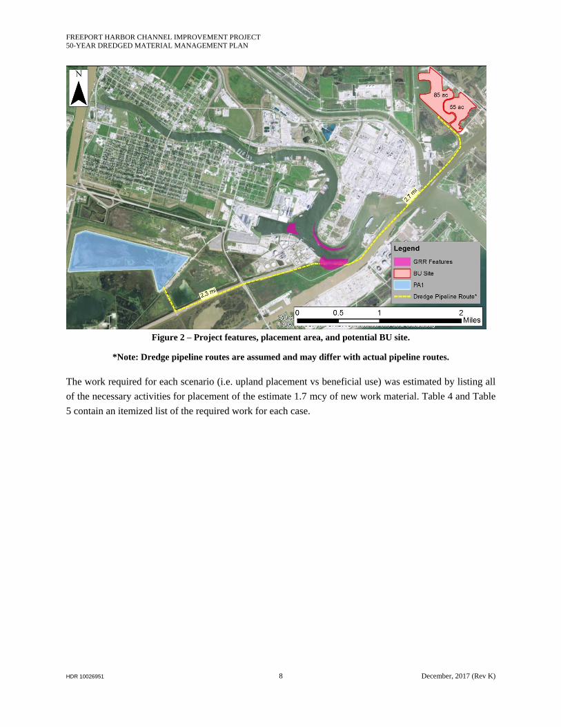
Figure 2 – Project features, placement area, and potential BU site.
*Note: Dredge pipeline routes are assumed and may differ with actual pipeline routes.
The work required for each scenario (i.e. upland placement vs beneficial use) was estimated by listing all
of the necessary activities for placement of the estimate 1.7 mcy of new work material. Table 4 and Table
5 contain an itemized list of the required work for each case.
FREEPORT HARBOR CHANNEL IMPROVEMENT PROJECT
50-YEAR DREDGED MATERIAL MANAGEMENT PLAN
HDR 10026951 9 December, 2017 (Rev K)
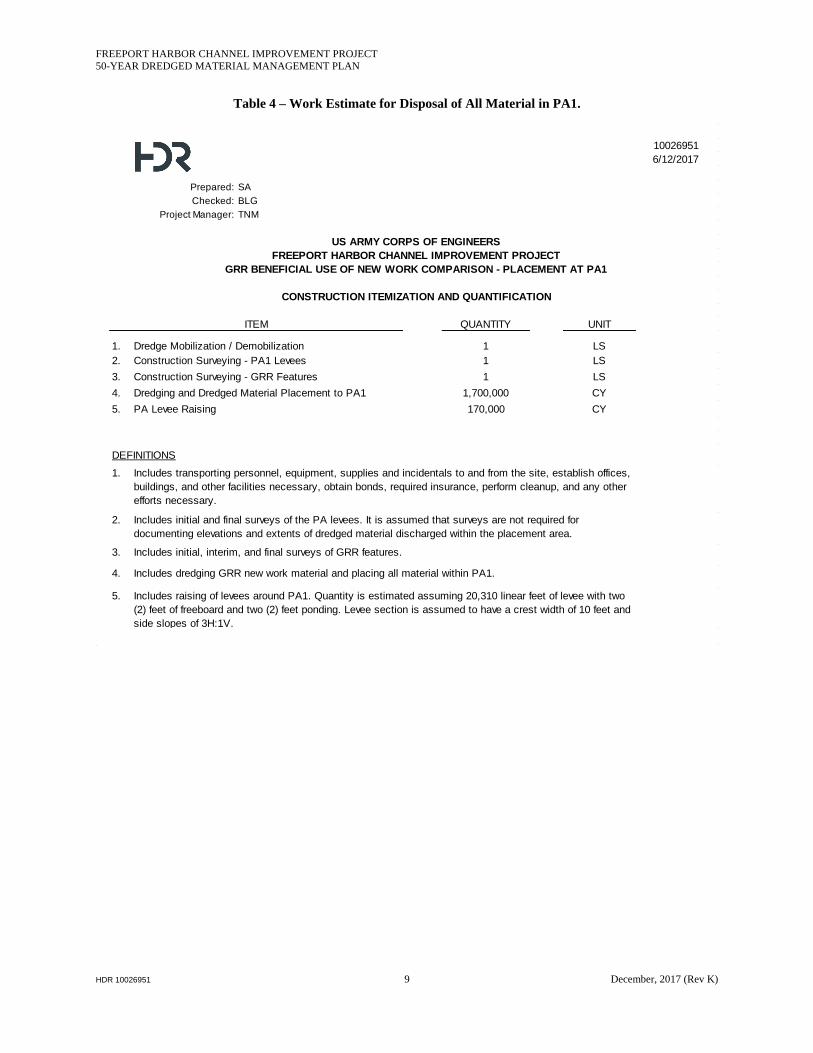
Table 4 – Work Estimate for Disposal of All Material in PA1.
10026951
6/12/2017
Prepared: SA
Checked: BLG
Project Manager: TNM
QUANTITY UNIT
1. Dredge Mobilization / Demobilization 1 LS
2. Construction Surveying - PA1 Levees 1 LS
3. Construction Surveying - GRR Features 1 LS
4. Dredging and Dredged Material Placement to PA1 1,700,000 CY
5. PA Levee Raising 170,000 CY
1.
2.
3.
4.
5.
ITEM
US ARMY CORPS OF ENGINEERS
FREEPORT HARBOR CHANNEL IMPROVEMENT PROJECT
GRR BENEFICIAL USE OF NEW WORK COMPARISON - PLACEMENT AT PA1
CONSTRUCTION ITEMIZATION AND QUANTIFICATION
Includes dredging GRR new work material and placing all material within PA1.
Includes raising of levees around PA1. Quantity is estimated assuming 20,310 linear feet of levee with two
(2) feet of freeboard and two (2) feet ponding. Levee section is assumed to have a crest width of 10 feet and
side slopes of 3H:1V.
DEFINITIONS
Includes transporting personnel, equipment, supplies and incidentals to and from the site, establish offices,
buildings, and other facilities necessary, obtain bonds, required insurance, perform cleanup, and any other
efforts necessary.
Includes initial and final surveys of the PA levees. It is assumed that surveys are not required for
documenting elevations and extents of dredged material discharged within the placement area.
Includes initial, interim, and final surveys of GRR features.
FREEPORT HARBOR CHANNEL IMPROVEMENT PROJECT
50-YEAR DREDGED MATERIAL MANAGEMENT PLAN
HDR 10026951 10 December, 2017 (Rev K)
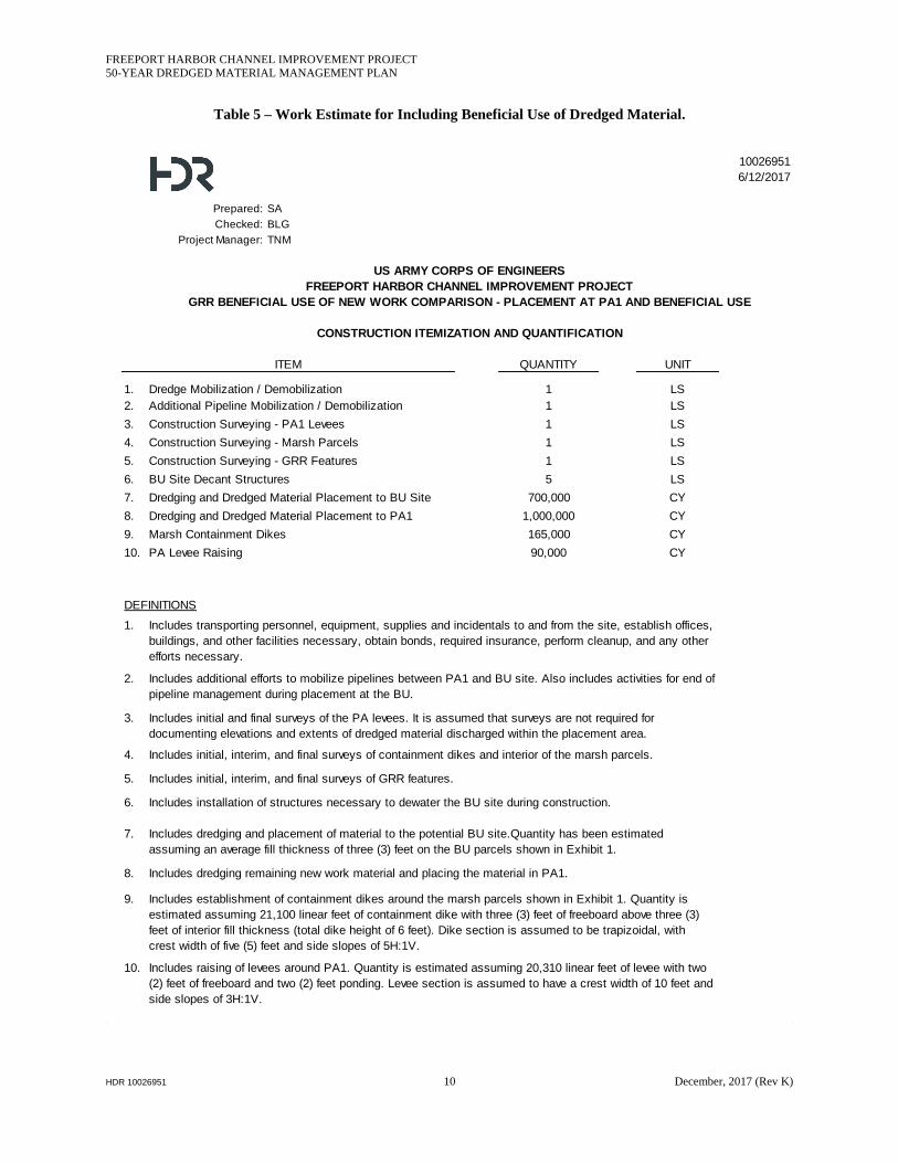
Table 5 – Work Estimate for Including Beneficial Use of Dredged Material.
10026951
6/12/2017
Prepared: SA
Checked: BLG
Project Manager: TNM
QUANTITY UNIT
1. Dredge Mobilization / Demobilization 1 LS
2. Additional Pipeline Mobilization / Demobilization 1 LS
3. Construction Surveying - PA1 Levees 1 LS
4. Construction Surveying - Marsh Parcels 1 LS
5. Construction Surveying - GRR Features 1 LS
6. BU Site Decant Structures 5 LS
7. Dredging and Dredged Material Placement to BU Site 700,000 CY
8. Dredging and Dredged Material Placement to PA1 1,000,000 CY
9. Marsh Containment Dikes 165,000 CY
10. PA Levee Raising 90,000 CY
1.
2.
3.
4.
5.
6.
7.
8.
9.
10.
ITEM
DEFINITIONS
Includes initial, interim, and final surveys of GRR features.
US ARMY CORPS OF ENGINEERS
FREEPORT HARBOR CHANNEL IMPROVEMENT PROJECT
GRR BENEFICIAL USE OF NEW WORK COMPARISON - PLACEMENT AT PA1 AND BENEFICIAL USE
CONSTRUCTION ITEMIZATION AND QUANTIFICATION
Includes initial and final surveys of the PA levees. It is assumed that surveys are not required for
documenting elevations and extents of dredged material discharged within the placement area.
Includes initial, interim, and final surveys of containment dikes and interior of the marsh parcels.
Includes additional efforts to mobilize pipelines between PA1 and BU site. Also includes activities for end of
pipeline management during placement at the BU.
Includes transporting personnel, equipment, supplies and incidentals to and from the site, establish offices,
buildings, and other facilities necessary, obtain bonds, required insurance, perform cleanup, and any other
efforts necessary.
Includes dredging remaining new work material and placing the material in PA1.
Includes establishment of containment dikes around the marsh parcels shown in Exhibit 1. Quantity is
estimated assuming 21,100 linear feet of containment dike with three (3) feet of freeboard above three (3)
feet of interior fill thickness (total dike height of 6 feet). Dike section is assumed to be trapizoidal, with
crest width of five (5) feet and side slopes of 5H:1V.
Includes raising of levees around PA1. Quantity is estimated assuming 20,310 linear feet of levee with two
(2) feet of freeboard and two (2) feet ponding. Levee section is assumed to have a crest width of 10 feet and
side slopes of 3H:1V.
Includes installation of structures necessary to dewater the BU site during construction.
Includes dredging and placement of material to the potential BU site.Quantity has been estimated
assuming an average fill thickness of three (3) feet on the BU parcels shown in Exhibit 1.
FREEPORT HARBOR CHANNEL IMPROVEMENT PROJECT
50-YEAR DREDGED MATERIAL MANAGEMENT PLAN
HDR 10026951 11 December, 2017 (Rev K)
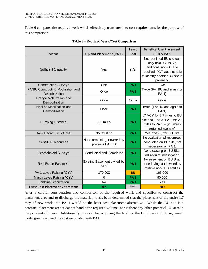
Table 6 compares the required work which effectively translates into cost requirements for the purpose of
this comparison.
Table 6 – Required Work/Cost Comparison
After a careful consideration and comparison of the required work and specifics to construct the
placement area and to discharge the material, it has been determined that the placement of the entire 1.7
mcy of new work into PA 1 would be the least cost placement alternative. While the BU site is a
potential placement area it cannot handle the required volume, nor is there any other potential BU area in
the proximity for use. Additionally, the cost for acquiring the land for the BU, if able to do so, would
likely greatly exceed the cost associated with PA1.
Metric Upland Placement (PA 1)
Least
Cost
Benefical Use Placement
(BU) & PA 1
Sufficent Capacity Yes n/a
No, identified BU site can
only hold 0.7 MCYs
additional non-BU site
required. PDT was not able
to identify another BU site in
proximity.
Construction Surveys One PA 1 Two
PA/BU Constructing Moblization and
DemobilzationOnce PA 1
Twice (For BU and again for
PA 1)
Dredge Mobilization and
DemobilizationOnce Same Once
Pipeline Mobilization and
Demobilization Once PA 1
Twice (For BU and again to
PA 1)
Pumping Distance 2.3 miles PA 1
.7 MCY for 2.7 miles to BU
site and 1 MCY PA 1 for 2.3
miles to PA 1 = (2.5 miles
weighted average)
New Decant Structures No, existing PA 1 Yes, five (5) for BU Site
Sensitive ResourcesNone remaining, covered by
previous EA/EISPA 1
No evaluation of resources
conducted on BU Site, not
necessary on PA 1,
Geotechnical Surveys Conducted and Completed PA 1None existing on BU Site,
will require investigation
Real Estate EasementExisting Easement owned by
NFS PA 1
No easement on BU Site,
underlaying land owned by
multiple non-NFS entities
PA 1 Levee Raising (CYs) 170,000 BU 165,000
Marsh Levee Raising (CYs) 0 PA 1 90,000
Bankline Stabilization No PA 1 Yes
Least Cost Placement Alternative YES *** NO
FREEPORT HARBOR CHANNEL IMPROVEMENT PROJECT
50-YEAR DREDGED MATERIAL MANAGEMENT PLAN
HDR 10026951 12 December, 2017 (Rev K)
1.8 REFERENCES
HDR Engineering Inc. 2012; “Dredged Material Placement Area Capacity Assessment.” HDR Project
173803 presented at the Meeting with Freeport LNG, Freeport, TX; February 24, 2012.
HDR Engineering Inc. 2016; “Freeport Harbor Channel Improvement Project – General Reevaluation
Report H&H Analysis - Task 1: Sedimentation Analysis Memo”
United States Government, “Federal Register”, Volume 80, No.181, Friday September 18, 2015,
pp56395-56398
USACE, 2012a; “Freeport Harbor Channel Improvement Project Feasibility Report”, Volume I;
Galveston TX
USACE, 2012b; “Freeport Harbor Channel Improvement Project Feasibility Report”, Volume II;
Galveston TX
USACE, 2012c; “Final Environmental Impact Statement, Freeport Harbor Channel Improvement Project,
Brazoria County, TX”, Volume I; Galveston TX
WRRDA, 2014 “Water Resources Reform Development Act of 2014” United States House of
Representatives, Washington DC