1 Cooperation-based Routing in Cognitive Radio Networks · · 2016-08-05Cooperation-based Routing...
15
1 Cooperation-based Routing in Cognitive Radio Networks Arsany Guirguis ‡ , Mohammed Karmoose † , Karim Habak ? , Mustafa El-Nainay ‡ and Moustafa Youssef ?? ‡ Computer and Systems Engineering, Alexandria University, Alexandria, Egypt † Department of Electrical Engineering, Alexandria University, Alexandria, Egypt. ? School of Computer Science, College of Computing, Georgia Tech., Atlanta, Georgia, USA ?? Egypt-Japan Univ. of Sc. and Tech. (E-JUST), Alexandria, Egypt Email: [email protected], m h [email protected], [email protected], [email protected], [email protected] Abstract—Primary user activity is a major bottleneck for existing routing protocols in cognitive radio networks. Typical routing protocols avoid areas that are highly congested with primary users, leaving only a small fragment of available links for secondary route construction. In addition, wireless links are prone to channel impairments such as multipath fading; which renders the quality of the available links highly fluctuating. In this paper, we investigate using cooperative communication mechanisms to reveal new routing opportunities, enhance route qualities, and enable true coexistence of primary and secondary networks. As a result, we propose Undercover: a cooperative routing protocol that utilizes the available location information to assist in the routing process. Specifically, our protocol revisits a fundamental assumption taken by the state of the art routing pro- tocols designed for cognitive radio networks. Using Undercover, secondary users can transmit in the regions of primary users activity through utilizing cooperative communication techniques to null out transmission at primary receivers via beamforming. In addition, the secondary links qualities are enhanced using cooperative diversity. To account for the excessive levels of interference typically incurred due to cooperative transmissions, we allow our protocol to be interference-aware. Thus, cooperative transmissions are penalized in accordance to the amount of negatively affected secondary flows. We evaluate the performance of our proposed protocol via NS2 simulations which show that our protocol can enhance the network goodput by a ratio reaches up to 250% compared to other popular cognitive routing protocols with minimal added overhead. I. I NTRODUCTION Cognitive Radio Networks (CRNs) are imminent to pervade into all fields of wireless communications. We backup this assertion with three observations. First, with the inherent inefficiency of the static spectrum licensing policies [1] and proliferation of spectrum accessing mobile and IoT devices [2], we are quickly heading towards a wireless spectrum crisis [3]. Second, the industrial market is widely shifting focus towards CRNs: software defined radio technologies are expected to dominate the market in the coming years, with a $27.29 Bil- lions net worth of a market size by the year 2020 [4]. Finally, the FCC announced new regulations allowing for wireless spectrum reuse by unlicensed users [5]. These regulations allow the unlicensed secondary users (SUs) to access the spectrum as long as they do not interfere with the licensed primary users (PUs). One of the most challenging functionalities in cognitive radio networks is routing. Routing protocols for CRNs have attracted attention of a large number of researchers [6]. In these networks, the routing protocol’s logic aims to determine (1) the route to the destination and (2) the channels to be used along this route. More importantly, it ensures that the used routes do not interfere with the licensed PUs. Therefore, the research community has explored various forms of routing in cognitive radio networks [7]–[10]. These explorations led to the development of various routing protocols that suit these goals. One common assumption in existing routing protocols, however, causes a critical limitation of the routing process and therefore hinders CRNs to perform suitably for real-world applications. Specifically, the current state-of-art cognitive radio routing protocols assume that SUs inside the interference range of a certain PU can not utilize its licensed channel during its active periods. This assumption is too constraining in comparison to the FCC’s regulations, which only prevent SUs from interfering with the licensed PUs [5]. Such constrain- ing assumption leads to (1) wasting possible communication opportunities, (2) relying on relatively suboptimal routes due to PUs activities, and (3) being unable to construct routes in scenarios where PUs are highly dense and/or relatively active. The question then arises: “Can SUs utilize licensed channels that are occupied with active PUs, without interfering with them?” A partial answer to this fundamental question is found in the literature of physical layer communications. Cooperative communications [11], [12] have been extensively studied as a mean to enhance the reliability of communication links. By allowing transmitters/receivers to cooperatively encode/decode transmitted/received data, communication links can be ren- dered less vulnerable to negative communication environ- ments such as poor communication channels and excessive interference levels. One particular technique is Cooperative Beamforming [13], where precoding is employed cooperatively by a set of transmitters to null out transmission at particular directions of interest, while simultaneously combating poor arXiv:1608.01632v1 [cs.NI] 4 Aug 2016
Transcript of 1 Cooperation-based Routing in Cognitive Radio Networks · · 2016-08-05Cooperation-based Routing...

1
Cooperation-based Routing in Cognitive RadioNetworks
Arsany Guirguis‡, Mohammed Karmoose†, Karim Habak?, Mustafa El-Nainay‡ and Moustafa Youssef??
‡Computer and Systems Engineering, Alexandria University, Alexandria, Egypt†Department of Electrical Engineering, Alexandria University, Alexandria, Egypt.
?School of Computer Science, College of Computing, Georgia Tech., Atlanta, Georgia, USA??Egypt-Japan Univ. of Sc. and Tech. (E-JUST), Alexandria, Egypt
Email: [email protected], m h [email protected], [email protected],[email protected], [email protected]
Abstract—Primary user activity is a major bottleneck forexisting routing protocols in cognitive radio networks. Typicalrouting protocols avoid areas that are highly congested withprimary users, leaving only a small fragment of available linksfor secondary route construction. In addition, wireless links areprone to channel impairments such as multipath fading; whichrenders the quality of the available links highly fluctuating.In this paper, we investigate using cooperative communicationmechanisms to reveal new routing opportunities, enhance routequalities, and enable true coexistence of primary and secondarynetworks. As a result, we propose Undercover: a cooperativerouting protocol that utilizes the available location informationto assist in the routing process. Specifically, our protocol revisits afundamental assumption taken by the state of the art routing pro-tocols designed for cognitive radio networks. Using Undercover,secondary users can transmit in the regions of primary usersactivity through utilizing cooperative communication techniquesto null out transmission at primary receivers via beamforming.In addition, the secondary links qualities are enhanced usingcooperative diversity. To account for the excessive levels ofinterference typically incurred due to cooperative transmissions,we allow our protocol to be interference-aware. Thus, cooperativetransmissions are penalized in accordance to the amount ofnegatively affected secondary flows. We evaluate the performanceof our proposed protocol via NS2 simulations which show that ourprotocol can enhance the network goodput by a ratio reaches upto 250% compared to other popular cognitive routing protocolswith minimal added overhead.
I. INTRODUCTION
Cognitive Radio Networks (CRNs) are imminent to pervadeinto all fields of wireless communications. We backup thisassertion with three observations. First, with the inherentinefficiency of the static spectrum licensing policies [1] andproliferation of spectrum accessing mobile and IoT devices [2],we are quickly heading towards a wireless spectrum crisis [3].Second, the industrial market is widely shifting focus towardsCRNs: software defined radio technologies are expected todominate the market in the coming years, with a $27.29 Bil-lions net worth of a market size by the year 2020 [4]. Finally,the FCC announced new regulations allowing for wirelessspectrum reuse by unlicensed users [5]. These regulationsallow the unlicensed secondary users (SUs) to access the
spectrum as long as they do not interfere with the licensedprimary users (PUs).
One of the most challenging functionalities in cognitiveradio networks is routing. Routing protocols for CRNs haveattracted attention of a large number of researchers [6]. Inthese networks, the routing protocol’s logic aims to determine(1) the route to the destination and (2) the channels to be usedalong this route. More importantly, it ensures that the usedroutes do not interfere with the licensed PUs. Therefore, theresearch community has explored various forms of routing incognitive radio networks [7]–[10]. These explorations led tothe development of various routing protocols that suit thesegoals.
One common assumption in existing routing protocols,however, causes a critical limitation of the routing processand therefore hinders CRNs to perform suitably for real-worldapplications. Specifically, the current state-of-art cognitiveradio routing protocols assume that SUs inside the interferencerange of a certain PU can not utilize its licensed channelduring its active periods. This assumption is too constrainingin comparison to the FCC’s regulations, which only preventSUs from interfering with the licensed PUs [5]. Such constrain-ing assumption leads to (1) wasting possible communicationopportunities, (2) relying on relatively suboptimal routes dueto PUs activities, and (3) being unable to construct routes inscenarios where PUs are highly dense and/or relatively active.The question then arises: “Can SUs utilize licensed channelsthat are occupied with active PUs, without interfering withthem?”
A partial answer to this fundamental question is found inthe literature of physical layer communications. Cooperativecommunications [11], [12] have been extensively studied asa mean to enhance the reliability of communication links. Byallowing transmitters/receivers to cooperatively encode/decodetransmitted/received data, communication links can be ren-dered less vulnerable to negative communication environ-ments such as poor communication channels and excessiveinterference levels. One particular technique is CooperativeBeamforming [13], where precoding is employed cooperativelyby a set of transmitters to null out transmission at particulardirections of interest, while simultaneously combating poor
arX
iv:1
608.
0163
2v1
[cs
.NI]
4 A
ug 2
016

2
channel conditions to increase the reliability of transmissionlinks. Cooperative beamforming can therefore be well-fittedfor overcoming the aforementioned assumption: by allowingSUs to cooperatively null-out transmission at the directionsof active PUs, while maintaining secondary transmission atthe required level. Thus, physical layer communication mech-anisms provide the means for truly undercover communicationthat enables SUs to communicate without interfering with PUs.Although being well-established in the literature, cooperativebeamforming has been solely considered in Cognitive Radiosetups which involve single-hop transmission links [14]–[17].First steps have been taken towards developing multi-hop-based cooperative beamforming schemes. However, DZP [18]is the first to consider using cooperative beamforming in therouting process. But, this protocol only uses such mechanismfor route maintenance as a reaction to the PU activity not asa routing protocol.
In this paper, we take a second step towards answeringthat question. We investigate the possibility of employingcooperative beamforming techniques in CRNs in a multi-hop context to enables concurrent primary and secondarytransmissions in the same geographical area. We develop across-layer based routing protocol, Undercover, that utilizesthe available location information to route data towards theirdestination. Our proposed protocol enables SUs to constructcooperative groups that employ cooperative beamforming toeither enhance the attained secondary throughput or to null outreception at nearby PUs, thus allowing for simultaneous use ofthe spectrum by both PUs and SUs. Considering the elevatedlevels of interference commonly exhibited by cooperativetransmissions, we allow our protocol to be interference-awareby penalizing the routing situations which may incur exces-sive interference on on-going secondary flows. Our proposedprotocol is considered as a local one: each node is providedwith the necessary information about the network topology andwireless channel condition. This allows for a fully distributedimplementation of the protocol.
We evaluate the performance of Undercover via NS2 simu-lations [19] under various network conditions. We compareUndercover’s achieved performance against other cognitiveradio routing protocols. Our experiments show that Undercoverachieves up to 250% increase in goodput compared to otherprotocols. In addition, the done experiments show that thepath construction overhead introduced by Undercover enablesrelying on stable paths that avoid the rerouting overheadtriggered by PUs activity.
Overall, the contributions of this paper are as follows:1) Designing Undercover, a cooperative based routing
protocol that operates on the new opportunities anduses location information to aid the routing process.It utilizes the idea of beamforming to enable primaryand secondary transmission to co-exist, by allowingSU to null transmission in the directions of existingPUs. It also uses cooperation with neighboring nodesto increase secondary throughput.
2) Formulating the tradeoffs introduced by the need toenhance the path communication throughput while min-imizing the inter-path interference. For this, we analyze
the average achievable capacity using a single node anda cooperative group in the routing process. We alsodevelop a routing metric that is based on the achievablecapacity of single, as well as multiple transmittersemploying beamforming for a single-hop setup
3) Developing heuristics to shrink the search space ofchoosing nodes to participate in the coopeartive group.For this, we propose a group selection algorithm thatprovides candidate cooperative groups of SUs, whichoperates in small time that allows for practical usage.
4) Evaluating Undercover performance using NS2 simu-lations against other popular routing protocols that aredesigned for cognitive radio networks.
The rest of the paper is organized as follows. Section IIpresents some background material in addition to our relatedwork. We then describe our system model in Section III. Wepresent our routing objectives and propose our routing metricin Section IV. We then describe the whole routing protocol inSection V. Section VI evaluates our proposed routing protocoland Section VII concludes the paper and provides directionsfor future work.
II. BACKGROUND AND RELATED WORK
The wireless spectrum is a broadcast medium where differ-ent radio waves can constructively or destructively collide andaffect one another. The research community has thoroughlyinvestigated utilizing these effects to alter the signal trans-mission characteristics by allowing multiple users to transmitcarefully selected signals simultaneously and collaboratively[11], [12], [15]. These investigations have led to enhancingcommunication throughput [20], enabling simultaneous non-interfering transmissions [21], and reshaping the transmissionbeam [13].
There have been some attempts to exploit cooperative com-munication in the context of conventional wireless networks.These attempts were led by Khandani et al. who analyzed theenergy saving benefits introduced by employing cooperativediversity [22]. However, despite the sound theoretical frame-work, their proposed algorithms are not suitable for real-timecommunication. With similar energy efficiency goals, otherresearchers proposed more real-time suitable mechanisms instatic environments with wireless shadowing [23], [24] as wellas in multi-path environments [25], [26]. Other researchersfocused on enhancing the network throughput in case of havingmultiple concurrent flows [20], [27], [28].
The significant performance gains introduced by cooperativediversity have motivated some researchers to employ its tech-niques in the context of cognitive radio networks [29], [30].For instance, Ding et al. use cooperative diversity to transmitdata with higher capacity to maximize throughput [30]. Inaddition, Sheu et al. proposed a cooperative routing protocol in[31] that enhances the end-to-end throughput. Unfortunately,non of these approaches (1) offer new communication op-portunities, (2) mitigate the effect of having active primaryusers on the secondary network, (3) address the inter-pathinterference problem which increases as a result of cooperativetransmission.

3
One of the intensively studied cooperative communica-tions techniques is cooperative beamforming, which relies onsending precoded versions of the same data to reshape thesignal beam producing transmission nulls at certain spatialdirections [13]. A direct consequence of employing cooperativebeamforming is to allow for spatial multiplexing of concurrenttransmissions of multiple nodes [12]. Fortunately, cooperativebeamforming provides the means for hiding secondary usercommunication from primary users and avoiding interfer-ing with primary user communication. This opportunity wasconsidered by a small number of attempts like [17] whichutilizes beamforming by developing MAC layer protocols thatmaximize the received signal-to-noise ratio (SINR) among SUswith different power constraints and the QoS requirement ofPUs. However, this protocol deploys beamforming among onerelay node only between the source and the destination.
Our previous work [16] considered using beamformingin the routing layer. However, we only proposed a routemaintenance mechanism to alleviate the need for route re-establishment upon the detection of a PU which limits the use-fulness of beamforming. In this paper, we consider cooperativebeamforming a foundation for building successful cognitiveradio routing protocols. We understand the true potential ofemploying cooperative beamforming, mitigate its introducedinterference effects, and provide practical mechanisms forefficient cooperative group construction.
III. SYSTEM MODEL
In this section, we present our system assumptions and thenprovide a brief overview on the proposed routing protocol.
A. System AssumptionsThroughout this work, we assume the presence of a CRN
which consists of a set of stationary PUs that are licensed touse the spectrum according to their data delivery requirements.This is common in many CRN scenarios such as TV whitespace-based CRNs. We further assume that each SU knows itsown location and the location of its direct neighbors. A nodecan estimate its location using any of the current localizationsystems, including GPS [32] or cellular mobile-based systems[33]. Moreover, a sender can obtain the location informationof the ultimate destination via out of band services that mapnode addresses to locations, or have it disseminated throughthe network. Assuming knowing only the location of the des-tination is a typical and valid assumption in many applicationsincluding military and sensor networks where reporting nodesknow the locations of the sink nodes. We assume also thatSUs are able to sense and detect the PUs activity [34]. A set ofstationary SUs are allowed to use the spectrum in a manner thatdoes not jeopardize the integrity of the PU transmissions, withmaximum transmission power of PT for each SU. Assumingthat the primary network adopts an overlay transmission policy,a SU is not allowed to transmit except in two cases: 1) a PUis not currently active, in which case a SU is permitted tooccupy the spectrum for a period which terminates with the re-occupation of a PU to the spectrum, or 2) concurrently with thePU only if a SU is able to employ cooperative beamforming.
It is vital to mention here that interference must be avoided atthe receiving end of the primary link. Therefore, we assumethroughout this work that a PU signifies a primary receiver, andthat concurrent transmission is only allowed if interference isavoided at the receiver side. We assume also a slow fadingmulti-path wireless channel, in which a channel coefficientis constant over a period of Tc. A short Tc would requirefrequent estimation of the channel coefficients, while a longTc alleviates this requirement.
Primary receiver detection can be done via overhearing anddecoding reply messages sent by the receiving nodes, suchas ARQ or CTS packets. Assume that PUs are separatelyidentified by each of the SU nodes in the network. Such anassumption can be validated by observing that decoding ARQor CTS packets sent by PUs. This gives the SU identifying in-formation of the PU, such as the MAC address of its equippedNIC card. In order to perform accurate beamforming, reliableestimates of the channel coefficients between the transmittingSUs and the PU should be acquired, and this can be achievedby employing channel estimation techniques on the preamblesof those packets [35]. SUs are assumed to communicate controlpackets over a dedicated Common Control Channel (CCC)such as the 2.45GHz ISM band [36].
B. Routing Protocol OverviewWe assume that our protocol will be deployed in a cognitive
radio network that employs an overlay transmission policy. Insuch network, PUs and SUs cannot transmit signals simul-taneously except via cooperative beamforming. When somenode has a data packet to send, it broadcasts a route request(RREQ) packet to all of its neighbors and waits for replies.First, each neighbor is checked for its ability to host the datapacket to the target destination. A neighbor is able to be a partof the route if its distance to the final destination is less thanthe distance from the source to the destination. In this case,such neighbor is considered as a potential relay node for thistransmission. Each potential relay considers all of its neighbors(other than the source node) as possible next hops. For eachpossible next hop, the relay tries to construct different groupsof different sizes with its neighbors (excluding the potentialnext hop). For each potential constructed group, its routingmetric is calculated and saved. After trying all of the possiblegroups, the relay node finds the best group routing metric andsends it back as a route reply (RREP) packet to the requesternode.
A source originally generating a RREQ waits for a timeoutperiod during which it collects received RREP from neigh-boring nodes. Upon its termination, a node chooses the linkwith the highest link metric as the next hop, to which it sendsan ACK packet. As the next hop receives the ACK packet,it knows that it has been decided for the forwarding of thesource packet from the originating source. It then sends anAck Reply (AREP) packet to the source. Finally, it receivesthe data packet and becomes responsible for disseminating itto the constructed group so that all participating nodes in thisgroup can send it to the already chosen next hop. Such node,in this case, is called the group coordinator. When the next hop

4
DShSD
(a) Node-to-node case.
hcND
c1
c2
cN
hc1Dhc2DD
(b) Multi-node-to-node case.
Fig. 1: Existing options to transmitdata. This is used to clarify throughputcalculations.
DS
R
hSR hRD
hSD
Fig. 2: A scenario showing thedifference between sending as a single
node or as a group of two nodes.
DS
Interference range of node S
N3
N2
N1
Fig. 3: Illustrative example of interfer-ence effect.
receives the data packet, it repeats again the same algorithmto find the next hop on the route. This procedure is repeateduntil the data packet reaches its final destination.
TABLE I: Mathematical Notations
Symbol DescriptionPT Maximum transmission power for SUsPc Received power by some node due to the transmission of a
cooperative groupPint Interference limit of SUsPFSP The level of interference caused by a transmitting nodehsd Channel coefficient between two nodes s and dwij Beamforming weights between two nodes i and jσ2N Variance of Gaussian noise that affects each node in the networkB Available bandwidth for some particular linkCsd Achievable capacity between nodes s and dCcd Achievable capacity between cooperative group c and node dCcoop
ij Achievable capacity during cooperative transmission from i to jCwor
ij The worst capacity achieved to deliver the packet from thegroup coordinator to any of the neighbors participating in somecooperative transmission
Cij The effective capacity achieved through sending as a groupNf Number of on-going flows that are in the interference range of
the cooperative groupNn Number of flow-carrying direct neighbors of all the participating
nodes in the transmitting groupNmin The value of Nn for the minimum allowable group sizedr Radius of the circle describing the effective interference range of
some groupA Area covered by nodes participating in some groupDf Density of the flows surrounding some groupDn Node density around some node based on the two-hop neighbor
informationFn A rough estimate of the number of flows per node at nodes
surrounding some group
IV. MATHEMATICAL MODEL
In this section, we give the proposed mathematical formu-lation of our proposed routing metric. First, we give a briefoverview about the metrics that affect the routing decisions and
the incentives behind them. Then, we give the details of themathematical model for each of them. Finally, the completerouting protocol metric is given.
A. Overview
The proposed routing protocol aims at maximizing theachievable throughput across the network. Links along theroute are chosen based on the maximum achievable capacity.However, in order to account for throughput calculations alongthe links, a node should be aware of the sources inflictinginterference and therefore reducing the achievable capacitywhen transmitting to this node. A precise calculation of theinterference level due to all transmitting sources is a difficulttask, since it is now possible for two or more nodes that arenot in the interference range of the receiving node to inflictinterference if they engage in a cooperative transmission phase.In other words, cooperating groups in the network can causeconsiderable interference levels at relatively distanced nodesthat are unaware of this source of interference.
The incentive in adding the interference terms to the routingmetric is to penalize the use of cooperative groups in a mannerthat is proportional to the amount of expected interferenceincurred at nearby concurrent flows. The proposed metric isa composite of two components: the first gives an estimateof the achievable throughput across the links, and the secondcaptures the interference effect of using a cooperative groupacross the network. At this point, we make the assumptionthat the source node is not responsible to deliver the packet toall the cooperating nodes in the next hop. It is only requiredto deliver the data packet to the group coordinator which isresponsible for data dissemination among the collaboratingnodes. This should be taken into account in the calculation ofthe cost. Table I summarizes all mathematical notations thatare used throughout this paper.
5
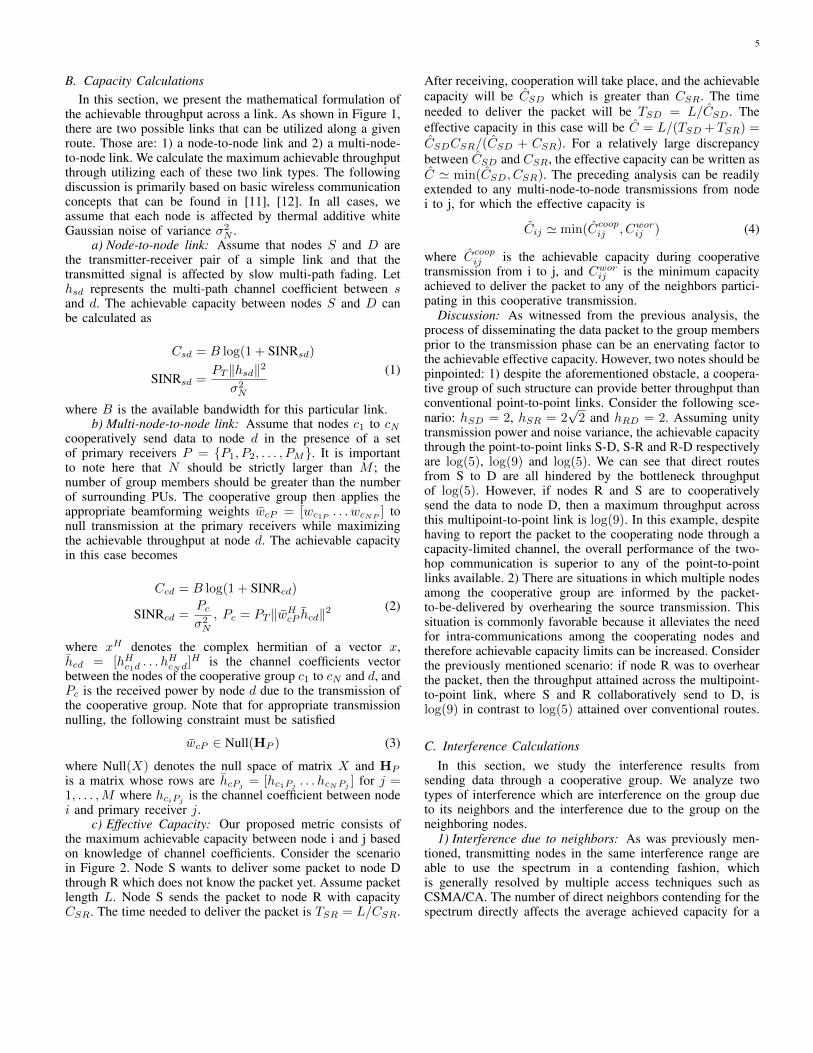
B. Capacity CalculationsIn this section, we present the mathematical formulation of
the achievable throughput across a link. As shown in Figure 1,there are two possible links that can be utilized along a givenroute. Those are: 1) a node-to-node link and 2) a multi-node-to-node link. We calculate the maximum achievable throughputthrough utilizing each of these two link types. The followingdiscussion is primarily based on basic wireless communicationconcepts that can be found in [11], [12]. In all cases, weassume that each node is affected by thermal additive whiteGaussian noise of variance σ2
N .a) Node-to-node link: Assume that nodes S and D are
the transmitter-receiver pair of a simple link and that thetransmitted signal is affected by slow multi-path fading. Lethsd represents the multi-path channel coefficient between sand d. The achievable capacity between nodes S and D canbe calculated as
Csd = B log(1 + SINRsd)
SINRsd =PT ‖hsd‖2
σ2N
(1)
where B is the available bandwidth for this particular link.b) Multi-node-to-node link: Assume that nodes c1 to cN
cooperatively send data to node d in the presence of a setof primary receivers P = {P1, P2, . . . , PM}. It is importantto note here that N should be strictly larger than M ; thenumber of group members should be greater than the numberof surrounding PUs. The cooperative group then applies theappropriate beamforming weights wcP = [wc1P . . . wcNP
] tonull transmission at the primary receivers while maximizingthe achievable throughput at node d. The achievable capacityin this case becomes
Ccd = B log(1 + SINRcd)
SINRcd =Pcσ2N
, Pc = PT ‖wHcP hcd‖2(2)
where xH denotes the complex hermitian of a vector x,hcd = [hHc1d . . . h
HcNd
]H is the channel coefficients vectorbetween the nodes of the cooperative group c1 to cN and d, andPc is the received power by node d due to the transmission ofthe cooperative group. Note that for appropriate transmissionnulling, the following constraint must be satisfied
wcP ∈ Null(HP ) (3)
where Null(X) denotes the null space of matrix X and HP
is a matrix whose rows are hcPj = [hc1Pj . . . hcNPj ] for j =1, . . . ,M where hciPj is the channel coefficient between nodei and primary receiver j.
c) Effective Capacity: Our proposed metric consists ofthe maximum achievable capacity between node i and j basedon knowledge of channel coefficients. Consider the scenarioin Figure 2. Node S wants to deliver some packet to node Dthrough R which does not know the packet yet. Assume packetlength L. Node S sends the packet to node R with capacityCSR. The time needed to deliver the packet is TSR = L/CSR.
After receiving, cooperation will take place, and the achievablecapacity will be CSD which is greater than CSR. The timeneeded to deliver the packet will be TSD = L/CSD. Theeffective capacity in this case will be C = L/(TSD +TSR) =CSDCSR/(CSD + CSR). For a relatively large discrepancybetween CSD and CSR, the effective capacity can be written asC ' min(CSD, CSR). The preceding analysis can be readilyextended to any multi-node-to-node transmissions from nodei to j, for which the effective capacity is
Cij ' min(Ccoopij , Cworij ) (4)
where Ccoopij is the achievable capacity during cooperativetransmission from i to j, and Cworij is the minimum capacityachieved to deliver the packet to any of the neighbors partici-pating in this cooperative transmission.
Discussion: As witnessed from the previous analysis, theprocess of disseminating the data packet to the group membersprior to the transmission phase can be an enervating factor tothe achievable effective capacity. However, two notes should bepinpointed: 1) despite the aforementioned obstacle, a coopera-tive group of such structure can provide better throughput thanconventional point-to-point links. Consider the following sce-nario: hSD = 2, hSR = 2
√2 and hRD = 2. Assuming unity
transmission power and noise variance, the achievable capacitythrough the point-to-point links S-D, S-R and R-D respectivelyare log(5), log(9) and log(5). We can see that direct routesfrom S to D are all hindered by the bottleneck throughputof log(5). However, if nodes R and S are to cooperativelysend the data to node D, then a maximum throughput acrossthis multipoint-to-point link is log(9). In this example, despitehaving to report the packet to the cooperating node through acapacity-limited channel, the overall performance of the two-hop communication is superior to any of the point-to-pointlinks available. 2) There are situations in which multiple nodesamong the cooperative group are informed by the packet-to-be-delivered by overhearing the source transmission. Thissituation is commonly favorable because it alleviates the needfor intra-communications among the cooperating nodes andtherefore achievable capacity limits can be increased. Considerthe previously mentioned scenario: if node R was to overhearthe packet, then the throughput attained across the multipoint-to-point link, where S and R collaboratively send to D, islog(9) in contrast to log(5) attained over conventional routes.
C. Interference CalculationsIn this section, we study the interference results from
sending data through a cooperative group. We analyze twotypes of interference which are interference on the group dueto its neighbors and the interference due to the group on theneighboring nodes.
1) Interference due to neighbors: As was previously men-tioned, transmitting nodes in the same interference range areable to use the spectrum in a contending fashion, whichis generally resolved by multiple access techniques such asCSMA/CA. The number of direct neighbors contending for thespectrum directly affects the average achieved capacity for a

6
transmitting node. This is demonstrated in Figure 3 where nodeS wants to communicate with node D in the presence of threeflow-carrying nodes in its interference range. Let CSD be theachievable capacity along the direct link between the two nodesin the presence of no interfering sources. Assuming the fairdistribution of the time allocation for the medium among the4 nodes, then we can state that the average achievable capacitybetween S and D in the presence of the interfering nodes isCSD/4. The same argument holds in case a cooperative groupis utilized instead of a single transmitting node. This concludesthat the number of flow-carrying nodes in the interferencerange of the source node/group is inversely proportional tothe average achievable capacity over the transmission link.
2) Auto-interference due to cooperative groups: A cooper-ative group inflicts a relatively higher level of interferenceon nearby nodes. Moreover, the effective interference rangeof a cooperative group is larger than that of a single node,which imposes extra difficulties in the design of an efficientinterference-aware routing protocol. The reason for this is thatconventional contention-handling protocols are oblivious tothese out-of-range transmissions and thus have no control overthem.
In order to alleviate this shortcoming, the proposed metricallows each transmitting node/cooperative group to keep trackof the interference inflicted by its own transmission. Dependingon the interference level, the use of this node/cooperative groupis penalized which affects the route decision. A node shouldkeep track of the on-going flows in its neighborhood; eachnode reports its witnessed flow IDs to its neighbors. Basedon the received information from all neighbors along withneighbors known locations, a node can build a statistical modelof the flow density in the surrounding area. We can estimate theinclusive area of the nodes by a general polygon whose verticesare the neighboring nodes. Assuming the obtained estimatearea is A, the flow density is thus
Df =Total number of distinguished flows
A(5)
In order to determine an estimate for the number of on-goingflows that are affected by the transmission of a cooperativegroup, the effective interference range of the group shouldbe also estimated. For simplicity, we assume that the fartransmissions are affected by Free-Space-Path (FSP) loss. Thelevel of interference caused by a transmitting node with powerPT at node situated at distance d can be approximated by
PFSP = PTc
d2(6)
where c is the free space path loss and its value depends onthe used frequency. Given an interference limit of secondarynodes Pint, a cooperative group consisting of N nodes canthen calculate its effective interference range which is definedas: the geographical area in which a secondary node is -inthe worst case- affected by an interference power greater thanPint, given the assumed FSP model. Assuming the worst casescenario (perfectly coherent addition of transmitted signals atany given point), the received power at any point (x, y, z) inspace due to cooperative group transmission is given by
Pr(x, y, z) = PT
N∑i=1
‖wi‖2
d2i(7)
where di is the distance between node i in the group and thepoint (x, y, z). For ease of calculations, we approximate theeffective transmission range of the cooperative group as if asingle node situated in the center of the group, and transmit-ting with a power equal to PT
∑Ni=1 ‖wi‖2. Accordingly, the
effective interference range is simply a circle of radius
dr =
√cPT
∑Ni=1 ‖wi‖2
Pint(8)
The expected number of affected on-going flows Nf cannow be calculated by Nf = Df × πd2r .
D. Proposed MetricBased on the above, the link metric between nodes i and j
can be formulated as follows:
LCij =Cij
Nn + β(Nf −Nn)(9)
where Cij is the maximum achievable capacity between nodei and j among all possibilities of transmission (either a singletransmitting source or cooperative groups), Nn is the numberof flow-carrying direct neighbors of all the participating nodesin the transmitting group, Nf is the number of on-goingflows that are in the interference range of the cooperativegroup (this is equal to 0 for a single transmitter), and β isa design parameter to alter the altruistic/egoistic behavior ofthe cooperative group. It should be noted that Nf is inherentlyinclusive to the flows witnessed by the nodes in the cooperativegroup. That is the reason for the subtraction in (9).
V. IMPLEMENTATION DETAILS
This section gives some practical and implementation detailsof the whole process. First, we present some practical issuesthat we consider for our routing protocol. Then, we give thedetails of the information exchanged among the nodes to servethe routing process. Finally, we present the whole flowchartof our algorithm along with an example that highlights howUndercover works.
A. Practical ConsiderationsOur proposed protocol chooses the best possible link for-
mation (with maximum link metric) among all possibilities ofcooperative group constructions. Specifically, a source nodesends a route request to its neighbors. Each of the neighborscalculates the link metric for all possibilities of transmissionto determine which group is the best, and then sends a replymessage to the source node for selection. The details of theprotocol are described in Section V. However, we discuss herethe details of the link calculation algorithm.
A node searches for the best link construction by calculatingthe link metric for all possibilities of cooperative transmissions.

7
Group Size 2 3 4 5 6 7 8 9 10Accepted
% Inc. inNn
1 PU 85.6 148.8 197 236 268.9 298.2 321.7 342.2 362.12 PU 36.3 75.5 111.5 145.4 174.1 199.1 220.7 241.83 PU 20.3 44.2 71.3 97.4 122.1 145.5 167.4
TABLE II: Acceptable percentage increase in Nn for different group sizes relative to minimum allowable group size. Thepresented values are based on Rayleigh channel model with unit variance.
These possibilities are all based on the inclusion of directneighbors of the potential relay node in a possible cooperativegroup. Assume the relay node has N direct neighbors, thencalculating the metric for all possible combinations of groupsis O(2N ). However, if we assume that the node calculatingthe link metric is in the interference range of M activePUs, then any allowed transmission should include at leastM + 1 cooperative nodes that are also in the interferencerange of these PUs. In other words, the number of nodesparticipating in the cooperative group should be strictly higherthan the number of surrounding PUs (N > M ). In thiscase, the complexity of the process of metric calculationswill be reduced. Nonetheless, the current realization of themetric calculations is of a relatively high complexity. In thenext discussion, we study the statistical characteristics of theproposed metric, based on which we reduce the complexityof the link calculation algorithm via less-probable candidateselimination.
1) Average achievable capacity: In this subsection, we studythe statistical behavior of the achievable capacity of differentlinks, and accordingly eliminate cooperation possibilities thatare less probable of attaining additional gains in link metric.Considering that the channel coefficients and, consequently,the beamforming weights presented in equations (1) and (2)are random variables. This renders the achievable capacity ofa particular link also of a statistical nature.
In fact, based on the wireless fading model and the instancesof the channel coefficients, the achievable capacity of a nodeor cooperative group links can be foreseen to fall in certainregions with high probability. Conversely, relatively high levelsof capacity are not likely to occur given a particular numberof nodes in a cooperative group and a given number of activePUs. Figure 4 shows the average maximum achievable capacitybased on the definitions given in Section IV-B for differentnumbers of cooperating nodes and different numbers of activePUs, for a Rayleigh fading model with unit variance. Notethat the achievable capacity in this case is measured by bitsper second per Hertz. This value should be multiplied by theused bandwidth to convert it to bits per second (bps).
For example, considering the case where no PUs are avail-able, it can be seen that moving from a single transmittingnode to the case of two cooperating nodes nearly multipliesthe average maximum achievable capacity of the link by afactor of 1.5, and moving to higher number of cooperatingnodes is accompanied with less relative gains in the achievablecapacity. A direct implication follows: considering the linkmetric construction in (9), the additional gain in the attained
capacity by including an extra node in the cooperative groupcannot be realized unless the accompanying increase in Nn isof less order.
Consider the scenario in Figure 5 in which all the presentednodes carry different data flows. Assume that node 0 calculatesthe link metric considering all possibilities of cooperation.Based on the previous discussion, using node 1 as a coop-erative pair will limit the value of the link metric since itwill increase the value of Nn by 3 in addition to the fouroriginally added by node 0 - an increment of 75% in Nn. Incontrast, using node 10 as a cooperative pair will not increaseNn beyond 4. Therefore, using node 10 will provide betterperformance than using node 3. The same argument can beconstructed for cooperative groups with a larger number ofnodes. It is important to highlight that a node that is notrelaying data for any of the existing flows is not affected bythe incurred interference and, therefore, is not included in thecalculations of Nn.
2) Elimination algorithm: Based on the above, our protocolis devised to reduce the search space by excluding the linkconstructions that are less probable to score maximum linkmetrics. Each node estimates a local version of the nodedensity based on the two-hop neighbor information it obtainsfrom periodic hello packets as
Dn = N/AN (10)
where N is the number of one-hop and two-hop neighbors ofthe node, and AN is the area of polygon whose vertices are thefarthest of these neighbors from the node. A rough estimateof the number of flows per node Fn can then be calculatemathematically as Fn = Df/Dn. A node can now calculatean estimate of the number of flows that would be affected bythe inclusion of N nodes in a group as N ×Fn. According tothis estimate, and based on the capacity gains shown in Figure4, a node then decides to exclude group formations that exceeda certain number of collaborating nodes. A node calculates the
following factorN × Fn −Nmin
Nminwhere Nmin is the value
of Nn for the minimum allowable group size (which is thenumber of PUs plus one as mentioned before in Section V-A).Based on comparing this factor to the corresponding thresholdin Table II1, the algorithm excludes groups of certain sizes
1Note that the values given in the table are for particular channel modeland statistics (Rayleigh channel model with unit variance), and would differfor other channel conditions. Values of this table depends on plotted valuesin Figure 4. Providing analytical expressions for the thresholds is a directextension of this work and is scheduled for later publications.

8
Number of SUs1 2 3 4 5 6 7 8 9 10
Ach
ieva
ble
Cap
acity
(b/
s/H
z)
0
1
2
3
4
5
6
7
No PU1 PU2 PU
Fig. 4: The effect of changing number of SUs and PUs on theaverage best achievable capacity assuming a Rayleigh fadingmodel with unit variance.
0
3
7
10
1
5
2
12
9
Fig. 5: An example on network scenario that shows the effect ofchoosing different groups on the achievable capactity.
from the search process. We calculate values of Table II asfollows: for each row of the table, an entry under group sizej is the percentage of increase in the achievable capacity,with corresponds to the achievable capacity of the minimumallowable group size. For example, the entry under groupsize seven in the second row is 174.1%. This means thatthe capacity achieved by groups of size seven is on average174.1% greater than the capacity achieved by groups of sizethree (which is the minimum allowable group size).
B. Information Exchange
In order to allow for the calculation of the achievable ca-pacities across links and the estimation of the on-going flows,a node should be provided periodically with the followinginformation:
1) its direct neighbors, and the channel coefficients be-tween the node and each neighbor,
2) the ID of the on-going flows witnessed by each of theneighbors,
3) the primary receivers that are detected by each of theneighboring nodes, and the estimated channel coeffi-cients, and
4) its 2-hop neighbors, and the channel coefficient betweeneach of these neighbors and its intermediate 1-hopneighbor.
We allow nodes to send periodic “Hello” packets to theirneighbors. A Hello packet consists of: 1) the ID of thegenerating node, 2) the IDs of the neighboring nodes, alongwith the channel coefficients between the node and each ofits neighbors, 3) the IDs of the identified PUs, along withthe estimated channel coefficients from the node to them,and 4) the IDs of the flows witnessed by the node2. Giventhis information, a node can calculate the three mandatory
2This can be obtained by the node by examining the header content of thepackets belonging to the flow.
estimates (Dn, Df and Fn) as discussed in Section IV forlink metric calculations.
C. Route Discovery
A source sends a Route Request (RREQ) packet whichcontains the IDs of the source and destination nodes. Uponreceiving a RREQ, a neighboring node decides whether tosend a Route Reply (RREP) packet or to discard the request(if its distance to the destination is greater than that of thesource), according to the algorithm described in Figure 6. Thisalgorithm is dissected into three phase:• Potential next hops: at the neighbor node, the algorithm
sweeps over all possible next hops for the relaying nodeapplying the algorithm. Only next hops that are closerto the destination are considered. First, minimum groupsize is set to be higher than number of neighboringPUs. Also, the value of Nmin is calculated in this phaseas described in Section V-A1. All neighboring nodesare tested one after another for being closer to thedestination. If the neighbor is closer to the destination,the algoithm moves to the second phase and if not, thisneighbor is discarded and the next neighbor is tested.
• Maximum Group Size Determination: basically, maxi-mum group size is set at least one plus the minimumgroup size. Then, the factor described in Section V-A1is calculated. Based on the elimination thresholds givenin Table II, the maximum allowable size is determined.At this state, we have the minimum and the maximumgroups sizes. We create all possible combinations ofgroups of all size in the described range for the currentpotential next hop. Each possible group enters the laststage.
• Link Metric Calculation: the algorithm calculates thelink metric (Equation 9) for all possible transmissionconfigurations between the node applying the algorithmand the possible next hop. If the current metric is the

9
Link Metric CalculationSTART
minGroupSize=Np+1maxGroupSize=minGroupSize
bestLinkMetric=0Nmin = Fn*minGroupSize
r = 1
maxGroupSize = maxGoupSize+1
Factor = (Fn*maxGroupSize-
Nmin)/Nmin
Is Factor< Threshold(Np)?
Link Metric Calculation
r = r + 1r >
length(R)?
Send LMbest
END
Yes
Is this neighbor closer to
destination? Yes
Is R(r) closer to
destination?
No
NoNo
Create power set of R of sizes from minGroupSize to
maxGroupSize --> P(minGroupSize,maxGroupSize)
Yes
Yes
length(R) == 0?
Yes
LinkMetric = MAX(LinkMetric,bestLinkMetric)
Np: Number of PUsminGroupSize: Minimum allowable group sizemaxGroupSize: Maximum allowable group sizebestLinkMetric: Best calculated Link MetricR: Set of node's neighbors excluding source, r: index of RNmin: Estimated number of flows identified by groups of size minGroupSizeP(x,y): Power set of R of sizes from x to yLinkMetric(P): Best link metric for all the elements of P(x,y)
No
No
Max. Group Size Determination
Potential Next Hops
LM
Fig. 6: Flowchart of the route reply algorithm applied by each neighbor of the source node.
01
7
9
52
D
RREQ
RREQ
(a) Some node on the route (node 0) sendsRREQ to its neighbors.
01
7
9
52
D
Coop. Group
Possible Dest.
Next Hop
(b) Trying groups of 2 for some possibledestination (node 7).
01
7
9
52
D
Coop.Group
Possible Dest.
Next Hop
(c) Trying groups of 3 for some possibledestination (node 7).
01
7
9
52
D
Coop. Group
Possible Dest.
Next Hop
(d) Trying groups of 2 for some possibledestination (node 9).
01
7
9
52
D
RREP
RREP
(e) All neighbors send their RREP to thesender node.
01
7
9
52
D
Next Hop
(f) Based on the RREPs, node 0 chooses node2 to be the next hop.
Fig. 7: Undercover routing scheme scenario.
maximum, it is stored in a variable as the maximummetric found for the current node. Finally, The maximumlink metric is then sent back to the source node in aRREP.
Once a node finishes the route reply algorithm, it sends aRREP packet which consists of 1) the source ID originatingthe RREQ, 2) the destination ID of the RREQ, and 3) the IDof the next node generating the RREP.
D. ExampleThe scenario in Figure 7 shows how the routing protocol
works. Suppose that some intermediate node (node 0) has adata packet to forward to some destination (node D). First, it
sends a RREQ (Figure 7a) to all its direct neighbors whichare nodes 1 and 2. Each of these nodes applies the routereply algorithm to choose the best group to cooperate with. Forexample, node 1 (for some possible intermediate destination,let it be node 7, as shown in Figure 7b) tries to constructgroup of two nodes with all of its direct neighbor (other thanthe sender node). Then, it tries to construct a group of threenodes (Figure 7c) and so on. It repeats the same scenario forall possible intermediate destinations like node 9 in Figure 7d.After finishing, all neighbors of the source node send backtheir RREPs (Figure 7e). Finally, the sender node chooses oneof those neighbors to be the next hop (Figure 7f) based onthe routing protocol metric described in Section IV. Then therouting process continues to the destination in the same way.

10
Parameter Value range Nominal Value(s)Number of PUs 2 - 16 4Number of SUs 10 - 40 25SU transmission range (m) 125 125PU transmission range (m) 140 140Number of connections 1 - 16 8Frequency (GHz) 2.4 2.4Effective bandwidth (Mbps) 1.5 1.5Packet Size (byte) 128 - 1518 512PU Activity(%) 0 - 100 20Data Rate Per Source (kbps) 20 - 400 100Deployment Area Side Length (m) 250 - 1000 250τ (sec) 1 1
TABLE III: Experiments parameters.
VI. PERFORMANCE EVALUATION
In this section, we evaluate the performance of our proposedrouting protocol using a cognitive extension of NS2 [19], [37].Table III summarizes the simulation parameters used in ourevaluation. We model the PUs activity as an ON-OFF processwhere the means of the exponentially distributed active andinactive periods are randomly chosen (according to a uniformdistribution) with the activity percentage shown in Table III.PUs are uniformly distributed over the available grid. Weassume the channel coefficients to be complex numbers thatfollow Gaussian distribution with zero mean and unit variance[38], [39].We assume that the SUs are randomly deployedusing a uniform distribution across the grid. Each SU nodeis equipped with two radio interfaces and has omni-directionalantennas and runs the IEEE 802.11 MAC protocol. The firstradio is used for exchanging the control packets while thesecond is used for exchanging data. The source and destinationof each connection are selected randomly. We compare ourprotocol against existing protocols such as LAUNCH [10] andCAODV [40]. LAUNCH is a location-aided routing protocolthat is designed to work in Cognitive Radio Networks. CAODVis the cognitive extension of the popular AODV protocol [41].We have chosen these two protocols as representatives forthe local and global approaches of routing protocols of CRNsrespectively.
A. Metrics
We evaluate Undercover using the following metrics:1) Goodput: number of bits communicated successfully
from the source to the destination per second.2) Average end-to-end delay: average time taken by pack-
ets to reach the destination from the source.3) Routing overhead: number of transmitted control pack-
ets in the routing phase.4) Average group size: average number of nodes partici-
pating in the cooperative commuication in case of usingUndercover.
5) Routing Opportunities Gain: average number of groupssuch a node can construct to route through. This numberconverges to one if no groups are used and hence wecalled it gain.
0
100
200
300
400
500
600
250 500 750 1000
Goo
dput
(K
bps)
Deployment Area Side Length (m)
UndercoverLAUNCHCAODV
(a) Goodput
0 0.5
1 1.5
2 2.5
3 3.5
4 4.5
5
250 500 750 1000
End
-to-
end
Del
ay (
sec)
Deployment Area Side Length (m)
UndercoverLAUNCHCAODV
(b) Average End-to-end Delay
Fig. 8: Effect of changing deployment area size on networkperformance.
B. Experimental Results
1) Changing Network Density:a) Changing Deployment Area Size: Figure 8 shows the
effect of changing the deployment area size on the performancemetrics. Increasing the square deployment area side lengthincreases its area and decreases the SUs density. We can see thesame observations highlighted in the previous section in termsof the behavior of goodput and delay when network densitychanges. However, it is vital to mention here that using thesmall area (250m×250m) for all of the next experiments wasdriven by the need to test Undercover in dense environmentto allow for groups formation.
b) Changing Number of SUs: Figure 9 shows the ad-vantage of using Undercover over CAODV and LAUNCHin terms of the achieved goodput and average end-to-enddelay as the SU density increases. Several conclusions canbe drawn from this figure. Generally, goodput increases withthe increase of SUs’ density. This happens since we can findbetter routes as the number of SUs increases. Also, we can seethat Undercover outperforms both of LAUNCH and CAODVin terms of goodput especially at high density of SUs. This isdue to the ability of Undercover to construct better and largercooperative groups with this increase where, groups of size 8were attained in some experiments. This leads to more reliabledelivery of packets to destinations. Our last note for Figure 9ais that in high density networks, LAUNCH beats CAODV sincethe former technique for routing takes into consideration theminimum delay and the PU presence.
Concerning Figure 9b, we can see a bell-like shape with apeak at some point in the graph for all protocols. This behaviorcan also be observed in Figure 9c and can be attributed to thefollowing reason. There are two competing factors that affectthe queues length and hence the delay. The first one is thenumber of transmissions between the sender and the receiverwhich affects the queuing delay at each node on the route. Thisfactor inceases with the increase of number of SUs as shown inFigure 9a. The second one is the advantage of finding betterroutes as the number of SUs increases which decreases thetotal end-to-end delay since the probability to interfere witha PU decreases. At the first part of the graph, the first factorbeats the second one. Thus, increasing SUs density increasesthe backoff delay and the number of retransmissions due to

11
100 150 200 250 300 350 400 450 500 550 600 650
10 15 20 25 30 35 40
Goo
dput
(K
bps)
Number of SUs
UndercoverLAUNCHCAODV
(a) Goodput
0 1 2 3 4 5 6 7 8 9
10
10 15 20 25 30 35 40
End
-to-
end
Del
ay (
sec)
Number of SUs
UndercoverLAUNCHCAODV
(b) Average End-to-end Delay
0
5
10
15
20
25
30
10 15 20 25 30
Ave
rage
Que
ue L
engt
h
Number of SUs
UndercoverLAUNCHCAODV
(c) Average Queue Length.
0
200
400
600
800
1000
1200
10 15 20 25 30 35 40Rou
ting
Opp
ortu
nitie
s G
ain
Number of SUs
Undercover
(d) Routing Opportunites Gain.
Fig. 9: Effect of changing number of SUs on network perfor-mance.
the congestion at the MAC layer. This increases the queuelength at each node (Figure 9c) increasing the total end-to-enddelay. However, in the second half of the graph, the oppositecase happens where we can see the effect of the second factor.Then, the advantage of finding better routes (and hence gettingbetter experience for data delivery) shows upper hand over thecounter effect of increasing queuing delay (due to SUs numberincrease) i.e. queues length decreases at each node as shown inFigure 9c. This leads to the decrease of the average end-to-enddelay as the SUs density increases at the end.
We can see that CAODV always has higher delay thanUndercover and LAUNCH. This happens since the last twoprotocols have the ability to deal better with the presenceof PUs either by constructing cooperative groups or by thechannel switching used by LAUNCH. On the other hand, theexperienced delays for Undercover and LAUNCH are nearlyequal in almost all cases since both try to avoid interfering PUsby sending on different channels or by nulling tranmission atthem. Although, the average end-to-end delay of Undercoverseems to be higher than that of LAUNCH in some cases, wecan get from Figure 10 a more detailed message. We cansee that in case of using Undercover, a very small portionof the packets suffers from excessive delays introduced byroute construction and this route is stable enough for morethan 90% of the packets. On the other hand, we can see thatless than 80% of packets transmitted using LAUNCH have thesame small delay. Thus, we can conclude that most of packetsrouted using Undercover incur very small delay compared toLAUNCH even if it seems to have higher average end-to-enddelay. Another conclusion can be driven from that figure: itseems that the groups construction phase takes a lot of timewhich makes about 10% on average have a high delay. This
0
0.2
0.4
0.6
0.8
1
0 10 20 30 40 50 60 70
CD
F
End-to-end Delay (Sec)
UndercoverLAUNCHCAODV
Fig. 10: CDF of end-to-end delay when using the defaultparameters of table III.
0
100
200
300
400
500
600
2 4 6 8 10 12 14 16G
oodp
ut (
Kbp
s)Number of PUs
UndercoverLAUNCHCAODV
(a) Goodput
-1 0 1 2 3 4 5 6 7 8 9
2 4 6 8 10 12 14 16
End
-to-
end
Del
ay (
sec)
Number of PUs
UndercoverLAUNCHCAODV
(b) Average End-to-end Delay
Fig. 11: Effect of changing number of PUs on networkperformance.
fact opens for us a room of improvements which can be doneas a future extension on the current work. This conclusioncan be applied too to the rest of the average end-to-end delayfigures in this section.
Figure 9d shows the effect of changing number of SUs onthe routing opportunities gain. This figure mainly comparesbetween Undercover and LAUNCH since the former protocolconverges to LAUNCH in case of not using groups. Thus,this figure shows the advantage of using cooperation withneighboring nodes. We can see that using cooperative groupsgives more routing opportunities in all cases. This leads tothe discovery of better and more stable paths and this factilluminate the value of cooperation used by Undercover. Wecan see that opportuniteis increase with the increase of numberof SUs, since more nodes exist to cooperate with. However, atvery dense network (when number of SUs = 40), the numberof opportunities decreases. This happens since not all thepotential groups are taken into consideration due to the criteriawe put in Section V-A to shrink the search space. This helpsus to save the computation time at each node. On the otherhand, number of opportunities offered by the non-cooperativeprotocol increases. Both factors lead to the decrease of theopportunities gain at the end of the figure.
2) Changing Number of PUs: Figure 11 shows the effect ofchanging number of PUs on the goodput and the end-to-end

12
50
100
150
200
250
300
350
400
450
0 20 40 60 80 100
Goo
dput
(K
bps)
PUs Activity
UndercoverLAUNCHCAODV
(a) Goodput
0 1 2 3 4 5 6 7 8 9
10
0 20 40 60 80 100
End
-to-
end
Del
ay (
sec)
PUs Activity
UndercoverLAUNCHCAODV
(b) Average End-to-end Delay
Fig. 12: Effect of changing PUs activity on network perfor-mance.
delay for the three used protocols for comparison. It can benoted that the performance for the three protocols degradesas the number of PUs increases. However, the performanceof Undercover always outperforms that of LAUNCH andCAODV in terms of the achieved goodput (Figure 11a). Thishappens since this target is our main concern while designingour new protocol. Thanks to the constructed cooperative group,Undercover can send in many cases without interfering PUseven if they exist and active. However, the overhead of creatingthese groups in terms of elapsed time and interference to otherscan be shown in Figure 11b in which we can see that thedelay for Undercover is higher than that of LAUNCH. Wecan note also in this figure that generally, the delay decreasesas number of PUs increases. Due to the greater effect of PUsas their number increases, the packet loss ratio increases. Thus,the number of correctly delivered packets to their destinationsdecreases, the queues length at each node decreases, and hencedecreasing the end-to-end delay.
3) Changing PUs Activity: Figure 12 shows the effect ofchanging PUs activity on the performance metrics. We canconclude from Figure 12a that the goodput decreases with theincrease of PUs activity. This happens since less number ofpackets are able to reach their destinations safely with theincrease of PUs activity decreasing the goodput with alwaysupper hand for Undercover over other protocols. There isalso an important observation in this figure. We can see thatUndercover beats other protocols in case of zero activity ofPUs. In this case, the network is converted from Cognitiveto Adhoc network i.e. no PU traffic in this case. This meansthat CAODV converges to AODV and LAUNCH advantage incognitive networks disappears. Cooperative groups constructedby Undercover in this case gives source node the ability to sendwith higher rate and hence achieving higher goodput. Thus,this figure shows the second goal of constructing cooperativegroups which is strengthing the sending power to get a signalwith better quality. We can note some other facts from Figure12b. Generally, the average end-to-end delay decreases withthe increase of PUs activity. This happens due to deliveringless number of packets and hence decreasing the congestionat MAC layer and the queue length at each node decreasingthe total delay. We can note that at 100% activity, CAODVachieves the lowest time delay and the lowest goodput (highest
0
100
200
300
400
500
600
0 2 4 6 8 10 12 14 16
Goo
dput
(K
bps)
Number Of Flows
UndercoverLAUNCHCAODV
(a) Goodput
0 1 2 3 4 5 6 7 8 9
0 2 4 6 8 10 12 14 16
End
-to-
end
Del
ay (
sec)
Number of Flows
UndercoverLAUNCHCAODV
(b) Average End-to-end Delay
Fig. 13: Effect of changing number of flows on networkperformance.
loss rate). However, the delay increases at the first part of thegraph for some protocols due to the time spent in constructingcooperative groups (to overcome PUs existence and activity)in case of Undercover and the channel switching done byLAUNCH. But at high rates of PUs, the delay decreases finallyfor all protocols.
4) Changing Number of Flows: Figure 13 shows the ef-fect of increasing the number of active connections on theperformance metrics. From Figure 13a, we can note thatUndercover has the best performance when there is a largenumber of flows in the network. Where goodput saturates incase of using LAUNCH and CAODV while still increasing(even with a decreased rate) in case of using Undercover.This happens in case of LAUNCH and CAODV since thereare not enough SUs to accomodate flows. The same saturationeffect occurs with Undercover but at a later point on thegraph. This can be abstractly explained by thinking of networksoperating with Undercover as larger networks with virtualSUs that correspond to groups. Also, increasing number offlows increases the goodput as well. This is due to the factof transferring more packets to destinations which increasesthe goodput value by definition. We can see that Undercoverperformance exceeds that of CAODV and LAUNCH due to theability of delivering more packets for each single added flow,which is translated to enhanced performance. From Figure 13b,we can see an increase in the values of delay with the increaseof the number of active connections. This is due to the increaseof the number of deliverd packets to their destinations andhence, the increase of the delay due to congestion at the MAClayer.
5) Changing Data Rate Per Source: Figures 14 shows howUndercover beats other routing protocols for different datarates. System performance increases in terms of the goodputbut degrades in terms of the end-to-end delay for higher datarates. Some of the observations that are mentioned previouslycan be noted also in this figure.
6) Changing Packet Size: Figures 15 shows the effect ofchanging the packet size on the performance metrics for allused protocols for comparison. We can note generally that theaverage end-to-end delay (Figure 15b) increases as the packetsize increases. This happens since any packet needs more timeto reach its destination if its size increases. For Figure 15a, wecan see that the goodput increases to some value for packet

13
0
100
200
300
400
500
600
700
800
0 50 100 150 200 250 300 350 400
Goo
dput
(K
bps)
Data Rate per source (Kbps)
UndercoverLAUNCHCAODV
(a) Goodput
0 2 4 6 8
10 12 14 16 18
0 50 100 150 200 250 300 350 400
End
-to-
end
Del
ay (
sec)
Data Rate per source (Kbps)
UndercoverLAUNCHCAODV
(b) Average End-to-end Delay
Fig. 14: Effect of changing data rate per source on networkperformance.
100 150 200 250 300 350 400 450 500 550
0 300 600 900 1200 1500 1800
Goo
dput
(K
bps)
Packet Size (byte)
UndercoverLAUNCHCAODV
(a) Goodput
0
5
10
15
20
25
0 300 600 900 1200 1500 1800
End
-to-
end
Del
ay (
sec)
Packet Size (byte)
UndercoverLAUNCHCAODV
(b) Average End-to-end Delay
Fig. 15: Effect of changing packet size on network perfor-mance.
size then decreases again. The goodput increase at the firstpart of the figure happens due to delivering more data tofinal destinations when increasing the packet size. This case issimilar to that of increasing data rate observed in Figure 14.However, the goodput decreases after that since some packetscan not reach their destinations due to the introduced activityof PUs which preempt the sending process. So, these packetsare lost and less data are then transmitted to their destinationssafely. The last observation for this figure is that, we cansee that Undercover outperforms other protocols in terms ofgoodput when using any packet size.
7) Average Goup Size: Figure 16 shows the average sizefor the groups constructed by Undercover. It can be notedthat as the number of SUs increases, the ability to constructlarger group size increases. However, in almost all cases,Undercover prefers to construct small sized groups to decreasethe interference to the least possible effect especially when thenumber of PUs in the region of node’s transmission is low.
8) Routing Overhead: Figure 17 shows the effect of increas-ing the number of SUs on the routing overhead. From Figure17a, we can see that CAODV has always higher overheadcompared to both LAUNCH and Undercover. This is due tothe global routing approach used by CAODV which leadsto having always a higher overhead compared to the localrouting technique used by the other two protocols. Figure 17bcompares both LAUNCH and Undercover in terms of theiradded overhead packets. We can see that there is a nearlyconstant number of overhead packets added by Undercover to
1
1.5
2
2.5
3
5 10 15 20 25 30 35 40 45
Ave
rage
Gro
up S
ize
Number of SUs
Undercover
Fig. 16: Average size of groups constructed by Undercover.
0
500
1000
1500
2000
2500
10 15 20 25 30 35 40
Ove
rhea
d (P
acke
ts)
Number of SUs
UndercoverLAUNCHCAODV
(a) Comparison between thethree routing protocols
30
40
50
60
70
80
90
100
10 15 20 25 30 35 40
Ove
rhea
d (P
acke
ts)
Number of SUs
UndercoverLAUNCH
(b) Zoomed figure on the part oflow overhead protocols
Fig. 17: Effect of changing number of SUs on the routingoverhead.
help it in the groups construction process.
VII. CONCLUSION
In this paper, we proposed a new protocol Undercover across layering protocol that uses physical layer techniques inthe routing layer. Constructing cooperative groups and usingbeamforming can be used by secondary users to send datanormally even if primary users exist and are active throughnulling tranmissions at them. This property leads to betterpacket delivery ratio for Undercover than other protocols sincethey avoid the presence of primary users or send when they areinactive. Thus, the ability to send simultaneously with primaryusers opens a new degree of freedom that was not availablebefore. Also, cooperative groups idea is used to send signalsin adhoc networks with better qualities. Thus, although ourprotocol is designed mainly for Cognitive Radio Networks, itproves to be useful also in adhoc networks. Undercover is alsodesigned to be interference-aware protocol so that it can takeinto consideration the interference that constructed cooperativegroups can do on other routes and vice versa. NS2 is used forthe evaluation in terms of the achieved goodput and averageend-to-end delay. Undercover is compared against CAODVwhich is a representative for the geographical protocols andLAUNCH as an example from the location-aided routingprotocols. Undercover performs well achieving a goodput gain

14
that reaches up to 250% compared to other protocols. Also, itshows to have low overhead and reasonable end-to-end delay.
Future directions include finding a mathematical model forvalues in table II and a way to improve the group constructiontime. Also, an important extension is to implement a dynamicprotocol that assigns spectrum to the participating nodes ineach group. We are also planning to test our protocol on someof the emerging testbeds like CRC [42], CogFrame [43], andCRESCENT [44] to see the performance on real scenarios.
REFERENCES
[1] FCC Spectrum Policy Task Force, “Report of the spectrum efficiencyworking group,” 2002.
[2] “Facts and forecasts: Billions of things, trillions of dollars,” 2014(accessed November, 2015).
[3] Peter Rysavy, “Spectrum crisis?,” Information Week Magazine, pp.23–30, 2009.
[4] “Software-defined-radio market sees increased growth,” 2014 (accessedNovember, 2015).
[5] Radio Magazine, “Fcc adopts rules for unlicensed use of televisionwhite spaces,” Retrieved at, p. 4, 2008.
[6] Moustafa Youssef, Mohammad Ibrahim, Mohamed Abdelatif, Lin Chen,and Athanasios V Vasilakos, “Routing metrics of cognitive radionetworks: A survey,” Communications Surveys & Tutorials, IEEE, vol.16, no. 1, pp. 92–109, 2014.
[7] Moustafa Youssef, Mohammad Ibrahim, Mohamed Abdelatif, Lin Chen,and Athanasios V Vasilakos, “Routing metrics of cognitive radionetworks: A survey,” Communications Surveys & Tutorials, IEEE, vol.16, no. 1, pp. 92–109, 2014.
[8] Ioannis Pefkianakis, Starsky HY Wong, and Songwu Lu, “Samer:spectrum aware mesh routing in cognitive radio networks,” in NewFrontiers in Dynamic Spectrum Access Networks. DySPAN 2008. 3rdSymposium on. IEEE, pp. 1–5.
[9] Kaushik R Chowdhury and Marco Di Felice, “Search: A routingprotocol for mobile cognitive radio ad-hoc networks,” ComputerCommunications, vol. 32, no. 18, pp. 1983–1997, 2009.
[10] Karim Habak, Mohammed Abdelatif, Hazem Hagrass, Karim Rizc, andMoustafa Youssef, “A location-aided routing protocol for cognitiveradio networks,” in Computing, Networking and Communications(ICNC), International Conference on. IEEE, 2013, pp. 729–733.
[11] Andrea Goldsmith, Wireless communications, Cambridge universitypress, 2005.
[12] David Tse and Pramod Viswanath, Fundamentals of wireless commu-nication, Cambridge university press, 2005.
[13] Barry D Van Veen and Kevin M Buckley, “Beamforming: A versatileapproach to spatial filtering,” IEEE assp magazine, vol. 5, no. 2, pp.4–24, 1988.
[14] Xiaoming Chen, Hsiao-Hwa Chen, and Weixiao Meng, “Cooperativecommunications for cognitive radio networks—from theory to applica-tions,” Communications Surveys & Tutorials, IEEE, vol. 16, no. 3, pp.1180–1192, 2014.
[15] Xiaofeng Tao, Xiaodong Xu, and Qimei Cui, “An overview ofcooperative communications,” IEEE Communications Magazine, vol.50, no. 6, pp. 65–71, 2012.
[16] Mohammed Karmoose, Ahmed Sultan, and Moustafa Youssef, “Stabil-ity analysis in a cognitive radio system with cooperative beamforming,”in Wireless Communications and Networking Conference (WCNC).IEEE, 2013, pp. 637–642.
[17] Tao Yi, Li Guo, Kai Niu, Hongyan Cai, Jiaru Lin, and Wenbao Ai,“Cooperative beamforming in cognitive radio network with hybridrelay,” in 19th International Conference on Telecommunications (ICT).IEEE, 2012, pp. 1–5.
[18] Mohammed Karmoose, Karim Habak, Mustafa ElNainay, and MoustafaYoussef, “Dead zone penetration protocol for cognitive radio networks,”in Wireless and Mobile Computing, Networking and Communications(WiMob), 9th International Conference on. IEEE, 2013, pp. 529–536.
[19] S. Floyd S. McCanne, “NS network simulator,”http://www.w3schools.com/browsers/browsers os.asp.
[20] Sriram Lakshmanan and Raghupathy Sivakumar, “Diversity routing formulti-hop wireless networks with cooperative transmissions,” in IEEESECON, 2009, pp. 1–9.
[21] Christopher J Collier and Robert J Murray, “Transmission systemfor sending two signals simultaneously on the same communicationschannel,” Dec. 17 1991, US Patent 5,073,899.
[22] Amir E Khandani, Eytan Modiano, Jinane Abounadi, and LizhongZheng, “Cooperative routing in wireless networks,” in Advances inPervasive Computing and Networking, pp. 97–117. Springer, 2005.
[23] Amir Ehsan Khandani, Jinane Abounadi, Eytan Modiano, and LizhongZheng, “Cooperative routing in static wireless networks,” IEEETransactions on Communications, vol. 55, no. 11, pp. 2185–2192, 2007.
[24] Fulu Li, Kui Wu, and Andrew Lippman, “Energy-efficient cooperativerouting in multi-hop wireless ad hoc networks,” in 25th IEEE Inter-national Performance, Computing, and Communications Conference,IPCCC 2006., pp. 8–pp.
[25] A Ibrahim, Zhu Han, and KJ Ray Liu, “Distributed energy-efficientcooperative routing in wireless networks,” IEEE Transactions onWireless Communications, vol. 7, no. 10, pp. 3930–3941, 2008.
[26] Gentian Jakllari, Srikanth V Krishnamurthy, Michalis Faloutsos,Prashant V Krishnamurthy, and Ozgur Ercetin, “A cross-layer frame-work for exploiting virtual miso links in mobile ad hoc networks,” IEEETransactions on Mobile Computing, vol. 6, no. 6, pp. 579–594, 2007.
[27] Sriram Lakshmanan and Raghupathy Sivakumar, “Proteus: Multiflowdiversity routing for wireless networks with cooperative transmissions,”Mobile Computing, IEEE Transactions on, vol. 12, no. 6, pp. 1146–1159, 2013.
[28] Sushant Sharma, Yi Shi, Y Thomas Hou, Hanif D Sherali, and SastryKompella, “Cooperative communications in multi-hop wireless net-works: Joint flow routing and relay node assignment,” in INFOCOM,Proceedings. IEEE, 2010, pp. 1–9.
[29] Qian Zhang, Juncheng Jia, and Jin Zhang, “Cooperative relay toimprove diversity in cognitive radio networks,” IEEE CommunicationsMagazine, vol. 47, no. 2, pp. 111–117, 2009.
[30] Lei Ding, Tommaso Melodia, Stella N Batalama, and John D Maty-jas, “Distributed routing, relay selection, and spectrum allocation incognitive and cooperative ad hoc networks,” in 2010 7th AnnualIEEE Communications Society Conference on Sensor Mesh and Ad HocCommunications and Networks (SECON), pp. 1–9.
[31] Jang-Ping Sheu and In-Long Lao, “Cooperative routing protocol incognitive radio ad-hoc networks,” in IEEE Wireless Communicationsand Networking Conference (WCNC), 2012, pp. 2916–2921.
[32] P. Enge and P. Misra, “Special issue on GPS: The Global PositioningSystem,” Proceedings of the IEEE, 1999.
[33] M. Ibrahim and M. Youssef, “CellSense: An Accurate Energy-EfficientGSM Positioning System,” Vehicular Technology, IEEE Transactionson, vol. 61, no. 1, pp. 286–296, 2012.
[34] Arsany Guirguis, Raymond Guirguis, and Moustafa Youssef, “Primaryuser-aware network coding for multi-hop cognitive radio networks,” inGlobal Telecommunications Conference (GLOBECOM). IEEE, 2014.
[35] Elisabeth De Carvalho and Dirk TM Slock, “Maximum-likelihoodblind fir multi-channel estimation with gaussian prior for the symbols,”in IEEE International Conference on Acoustics, Speech, and SignalProcessing ICASSP-97, 1997, vol. 5, pp. 3593–3596.
[36] Arsany Guirguis, Mohamed Ibrahim, Karim Seddik, Khaled Harras,Fadel Digham, and Moustafa Youssef, “Primary user aware k-hoprouting for cognitive radio networks,” in Global TelecommunicationsConference (GLOBECOM). IEEE, 2015.

15
[37] “Cognitive radio extension.,” [Online]. Available:http://stuweb.ee.mtu.edu/ljialian/.
[38] Krishna Gomadam, Viveck R Cadambe, Syed Jafar, et al., “Approach-ing the capacity of wireless networks through distributed interferencealignment,” in Global Telecommunications Conference. IEEE, 2008,pp. 1–6.
[39] Kai Yu and Bjorn Ottersten, “Models for mimo propagation channels:a review,” Wireless Communications and Mobile Computing, vol. 2, no.7, pp. 653–666, 2002.
[40] Angela Sara Cacciapuoti, Cosimo Calcagno, Marcello Caleffi, and LuigiPaura, “Caodv: Routing in mobile ad-hoc cognitive radio networks,” inWireless Days (WD), IFIP. IEEE, 2010, pp. 1–5.
[41] C. Perkins, E. Belding-Royer, and S. Das, “Ad hoc on-demand distancevector (AODV) routing,” 2003.
[42] “The cognetive radio cloud (crc) testbed,” [Online]http://smartci.alexu.edu.eg/crc.
[43] Ahmed Saeed, Mohammad Ibrahim, Khaled Harras, Moustafa Youssef,et al., “A low-cost large-scale framework for cognitive radio routingprotocols testing,” in Communications (ICC), International Conferenceon. IEEE, 2013, pp. 2900–2904.
[44] Abdelrahman Asal, Ahmad Mamdouh, Ahmed Salama, Moamen El-gendy, Moamen Mokhtar, Muhammed Elsayed, and Moustafa Youssef,“Crescent: a modular cost-efficient open-access testbed for cognitiveradio networks routing protocols,” in Proceedings of the 19th annualinternational conference on Mobile computing & networking. ACM,2013, pp. 179–182.