Chapter 17 GUI Programming - Component Layout, Additional GUI Components
Upload
margery-randallCategory
view
221download
4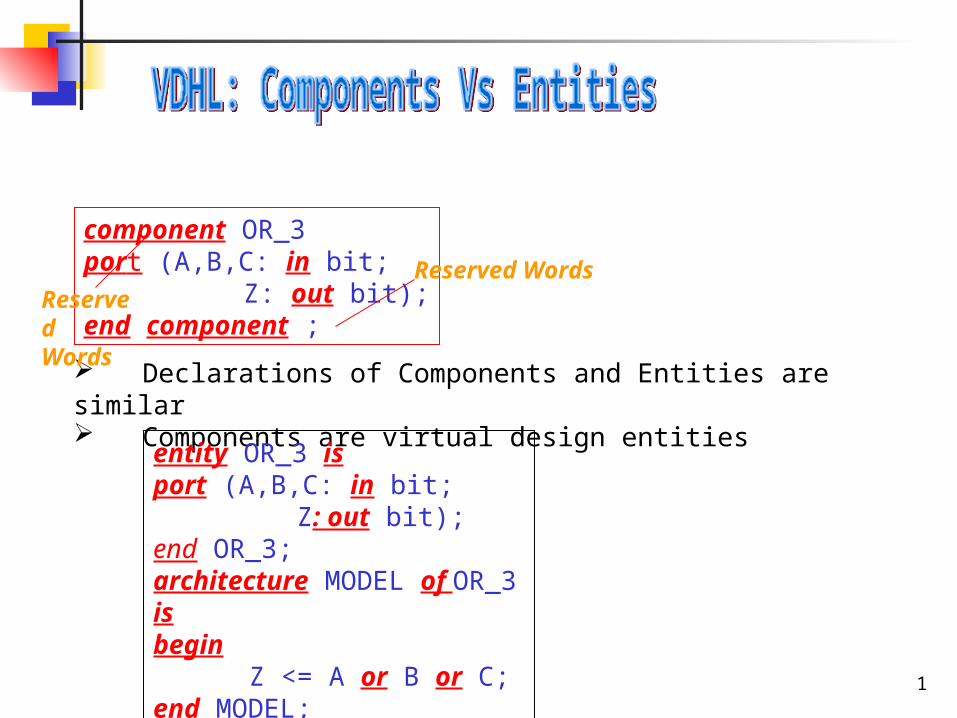
1
component OR_3port (A,B,C: in bit; Z: out bit);end component ;
Reserved Words
Declarations of Components and Entities are similar Components are virtual design entities
entity OR_3 isport (A,B,C: in bit; Z: out bit);end OR_3;architecture MODEL of OR_3 isbegin
Z <= A or B or C;end MODEL;
ReservedWords
2
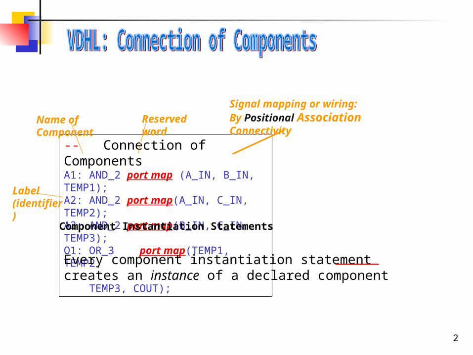
-- Connection of ComponentsA1: AND_2 port map (A_IN, B_IN, TEMP1);A2: AND_2 port map(A_IN, C_IN, TEMP2);A3: AND_2 port map(B_IN, C_IN, TEMP3);O1: OR_3 port map(TEMP1, TEMP2, TEMP3, COUT);
Reserved wordName of Component
Signal mapping or wiring:By Positional Association Connectivity
Label (identifier)
Component Instantiation Statements
Every component instantiation statement creates an instance of a declared component
3
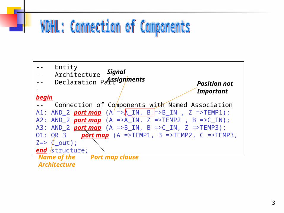
-- Entity -- Architecture-- Declaration Part
begin-- Connection of Components with Named AssociationA1: AND_2 port map (A =>A_IN, B =>B_IN , Z =>TEMP1);A2: AND_2 port map (A =>A_IN, Z =>TEMP2 , B =>C_IN);A3: AND_2 port map (A =>B_IN, B =>C_IN, Z =>TEMP3);O1: OR_3 port map (A =>TEMP1, B =>TEMP2, C =>TEMP3, Z=> C_out);end structure;
Name of the Architecture
Signal Assignments
Position not Important
Port map clause
4
• A hierarchical structure description is a powerful modeling construct in VHDL as it provides the mechanism to decompose the description of a large, complex digital system into smaller pieces.
• Structural hierarchies reflecting convenient functional & physical digital system decompositions is a good modeling practice.
Next few slides show how hierarchy is built in a Full Adder by using Half Adders and the Half Adder by using other components.
5
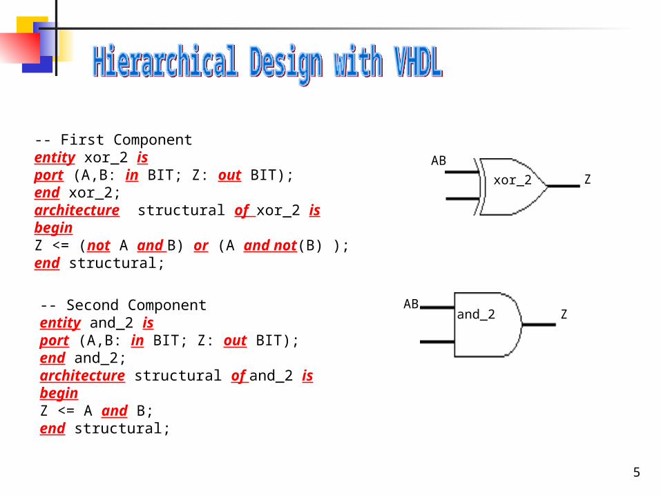
-- First Componententity xor_2 isport (A,B: in BIT; Z: out BIT);end xor_2; architecture structural of xor_2 isbeginZ <= (not A and B) or (A and not(B) );end structural;
-- Second Componententity and_2 isport (A,B: in BIT; Z: out BIT);end and_2; architecture structural of and_2 isbeginZ <= A and B;end structural;
xor_2
AB
Z
ABZand_2
6
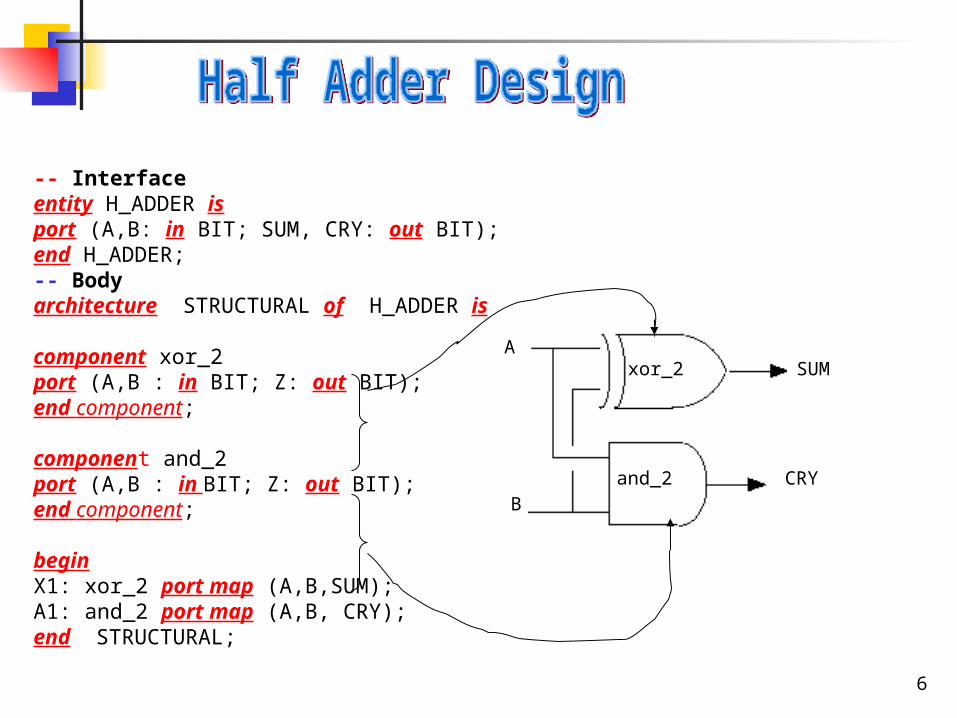
-- Interfaceentity H_ADDER isport (A,B: in BIT; SUM, CRY: out BIT);end H_ADDER;-- Body architecture STRUCTURAL of H_ADDER is
component xor_2port (A,B : in BIT; Z: out BIT);end component;
component and_2port (A,B : in BIT; Z: out BIT);end component;
beginX1: xor_2 port map (A,B,SUM);A1: and_2 port map (A,B, CRY);end STRUCTURAL;
CRY
SUM
B
A
and_2
xor_2
7
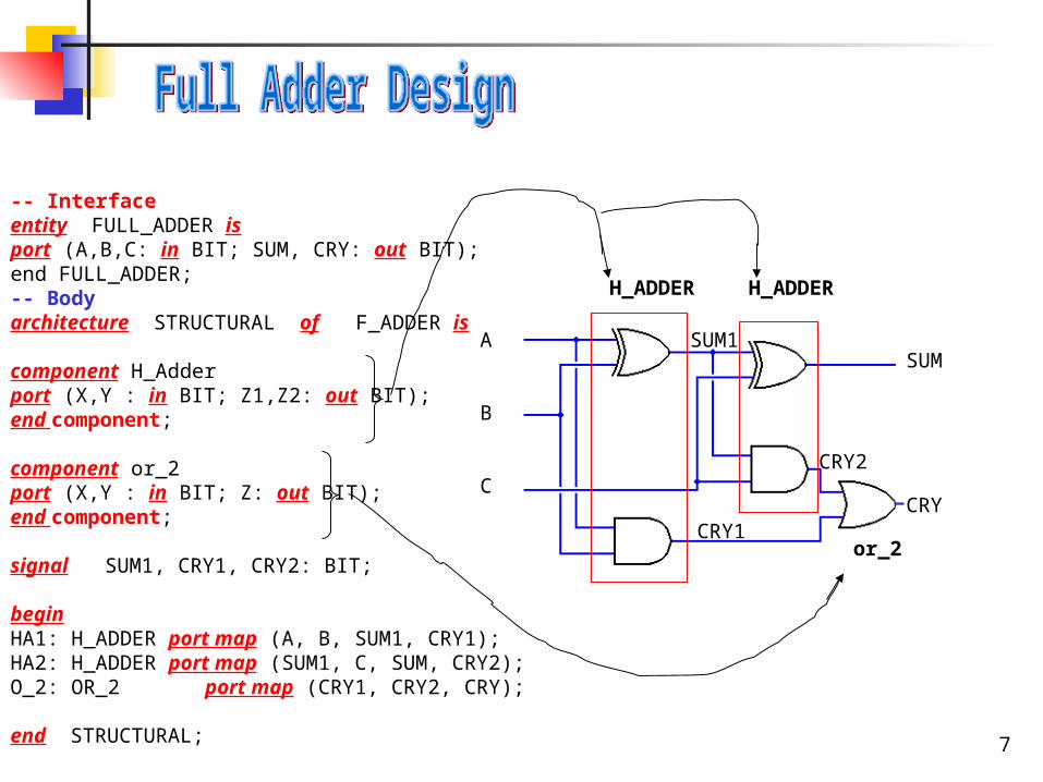
-- Interfaceentity FULL_ADDER isport (A,B,C: in BIT; SUM, CRY: out BIT);end FULL_ADDER;-- Body architecture STRUCTURAL of F_ADDER is
component H_Adderport (X,Y : in BIT; Z1,Z2: out BIT);end component;
component or_2port (X,Y : in BIT; Z: out BIT);end component;
signal SUM1, CRY1, CRY2: BIT;
beginHA1: H_ADDER port map (A, B, SUM1, CRY1);HA2: H_ADDER port map (SUM1, C, SUM, CRY2);O_2: OR_2 port map (CRY1, CRY2, CRY);
end STRUCTURAL;
SUM
CRY
SUM1
CRY1
CRY2
H_ADDER H_ADDER
or_2
A
B
C
8
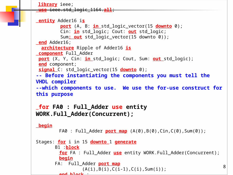
library ieee; use ieee.std_logic_1164.all; entity Adder16 is port (A, B: in std_logic_vector(15 downto 0); Cin: in std_logic; Cout: out std_logic; Sum: out std_logic_vector(15 downto 0)); end Adder16; architecture Ripple of Adder16 is component Full_Adder port (X, Y, Cin: in std_logic; Cout, Sum: out std_logic); end component; signal C: std_logic_vector(15 downto 0);-- Before instantiating the components you must tell the VHDL compiler--which components to use. We use the for-use construct for this purpose
for FA0 : Full_Adder use entity WORK.Full_Adder(Concurrent); begin FA0 : Full_Adder port map (A(0),B(0),Cin,C(0),Sum(0)); Stages: for i in 15 downto 1 generate B1 :block
for FA : Full_Adder use entity WORK.Full_Adder(Concurrent);begin
FA: Full_Adder port map (A(i),B(i),C(i-1),C(i),Sum(i));
end block ; end generate; Cout <= C(15); end Ripple;
9
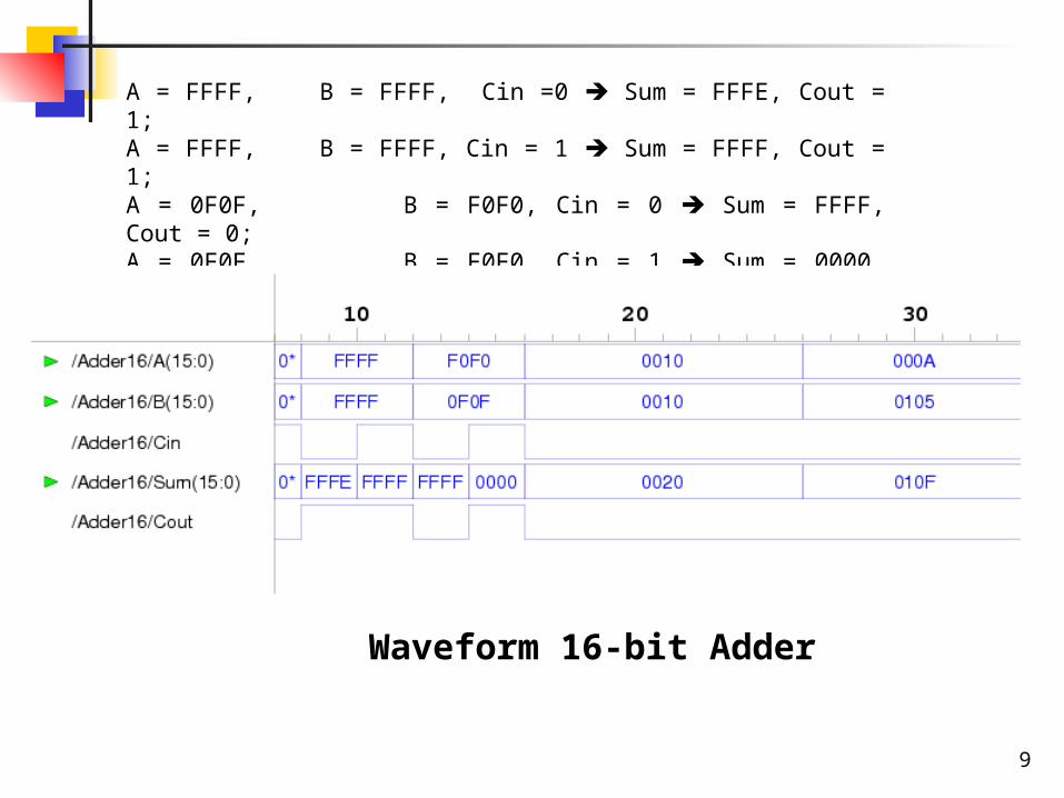
A = FFFF, B = FFFF, Cin =0 Sum = FFFE, Cout = 1;A = FFFF, B = FFFF, Cin = 1 Sum = FFFF, Cout = 1; A = 0F0F, B = F0F0, Cin = 0 Sum = FFFF, Cout = 0; A = 0F0F, B = F0F0, Cin = 1 Sum = 0000, Cout = 1;
Waveform 16-bit Adder
10
- In real life when building a pc board,usually the same components are often picked up from a storage area and placed on the board. VHDL structural description often use the same set of components. Repeating all the constructs to describe all the components is very tedious. The problem is solved by introducing the package concept.
- A package serves as a central place for frequently used utilities, such as component declarations.
- The needed component declaration is only written ONCE in a package.
- The declaration may then be accessed by any VHDL model by simply accessing the package.
11
- The use statement placed just before the architecture gives access to all the declarations in the package: use WORK.ASIM_LIB.all The statement above gives access to all component declarations in ASIM_LIB located in library WORK.
- The use statement allows the package ASIM_LIB to export its declarations.
- A package declaration is a design unit and can be analyzed by itself.
- It is important to have standard naming convention for components, type and signal names. Standard naming conventions can be enforced by declaring the commonly used names within a package.
12
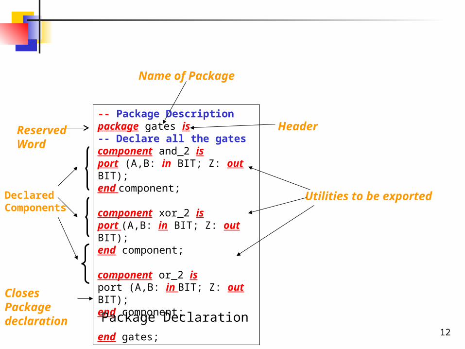
-- Package Descriptionpackage gates is-- Declare all the gatescomponent and_2 isport (A,B: in BIT; Z: out BIT);end component;
component xor_2 isport (A,B: in BIT; Z: out BIT);end component;
component or_2 isport (A,B: in BIT; Z: out BIT);end component;
end gates;
Header
Utilities to be exported
Package Declaration
Reserved Word
Name of Package
Closes Package declaration
Declared Components
13
CRY
SUM
B
A
and_2
xor_2
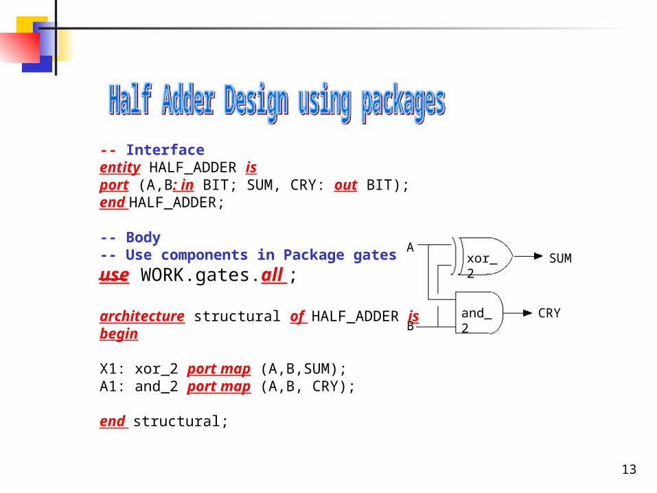
-- Interfaceentity HALF_ADDER isport (A,B: in BIT; SUM, CRY: out BIT);end HALF_ADDER;
-- Body -- Use components in Package gatesuse WORK.gates.all ;
architecture structural of HALF_ADDER isbegin
X1: xor_2 port map (A,B,SUM);A1: and_2 port map (A,B, CRY);
end structural;
14
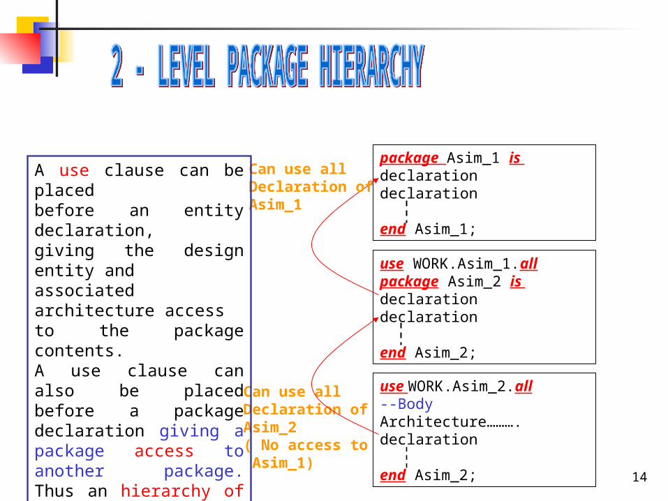
package Asim_1 is declarationdeclaration
end Asim_1;
use WORK.Asim_1.allpackage Asim_2 is declarationdeclaration
end Asim_2;
use WORK.Asim_2.all--BodyArchitecture……….declaration
end Asim_2;
Can use all Declaration of Asim_1
Can use all Declaration of Asim_2( No access to Asim_1)
A use clause can be placedbefore an entity declaration,giving the design entity andassociated architecture accessto the package contents.A use clause can also be placed before a package declaration giving a package access to another package. Thus an hierarchy of packagesis constructed in which the declarations of one package may be based upon declarations in other packages.
15
- In VHDL everything must be declared before it can be used. A declaration defines what a name represents.
- The scoping rules define the name space: Anything declared within the declaration part of an architecture may be used only within the architecture body.
Anything declared within a design entity declaration may be used only within the enclosing entity declaration and associated architecture.
Anything declared within a package declaration may be used within the enclosing package and also by the use statement in the other parts of VHDL
16
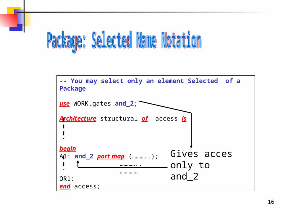
-- You may select only an element Selected of a Package
use WORK.gates.and_2;
Architecture structural of access is
beginA1: and_2 port map (………..); ………….. ……………OR1:end access;
Gives acces only to and_2
17
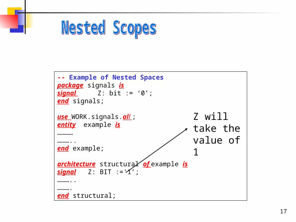
-- Example of Nested Spacespackage signals issignal Z: bit := ‘0’;end signals;
use WORK.signals.all ; entity example is…………………..end example;
architecture structural of example issignal Z: BIT :=‘1’;………..……….end structural;
Z will take the value of 1
18
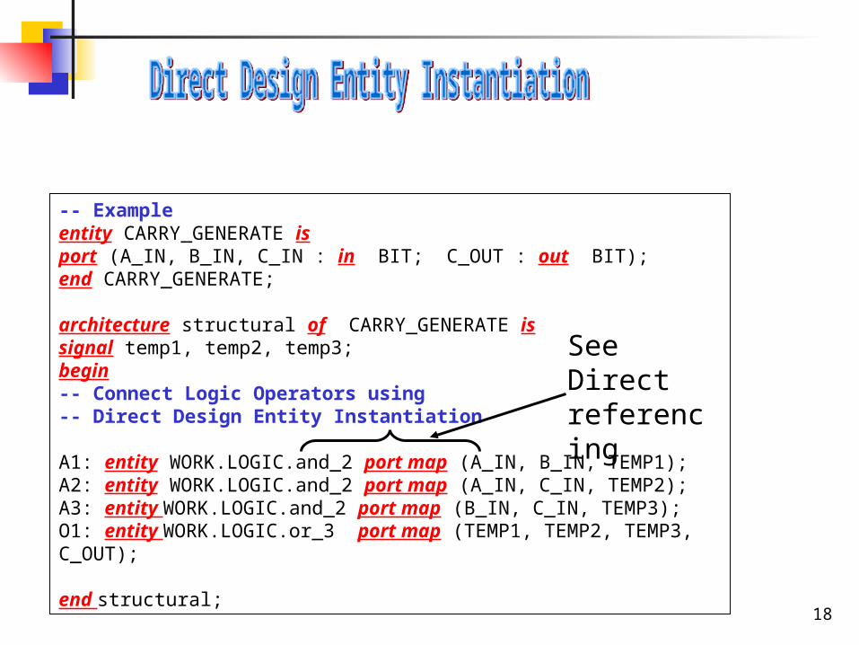
-- Example entity CARRY_GENERATE isport (A_IN, B_IN, C_IN : in BIT; C_OUT : out BIT);end CARRY_GENERATE;
architecture structural of CARRY_GENERATE issignal temp1, temp2, temp3;begin-- Connect Logic Operators using -- Direct Design Entity Instantiation
A1: entity WORK.LOGIC.and_2 port map (A_IN, B_IN, TEMP1);A2: entity WORK.LOGIC.and_2 port map (A_IN, C_IN, TEMP2);A3: entity WORK.LOGIC.and_2 port map (B_IN, C_IN, TEMP3);O1: entity WORK.LOGIC.or_3 port map (TEMP1, TEMP2, TEMP3, C_OUT);
end structural;
See Direct referencing
19
Architecture• Structural
• Behavioral Data FlowAlgorithmic
• MixedWe will use a full adder design to show the different architectural styles
20
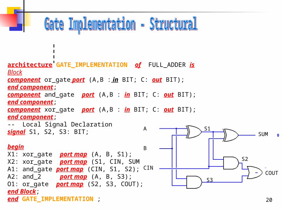
architecture GATE_IMPLEMENTATION of FULL_ADDER isBlockcomponent or_gate port (A,B : in BIT; C: out BIT);end component;component and_gate port (A,B : in BIT; C: out BIT);end component;component xor_gate port (A,B : in BIT; C: out BIT);end component;-- Local Signal Declarationsignal S1, S2, S3: BIT;
beginX1: xor_gate port map (A, B, S1);X2: xor_gate port map (S1, CIN, SUM);A1: and_gate port map (CIN, S1, S2);A2: and_2 port map (A, B, S3);O1: or_gate port map (S2, S3, COUT);end Block;end GATE_IMPLEMENTATION ;
SUM
COUT
S1
S3
S2
A
B
CIN
21
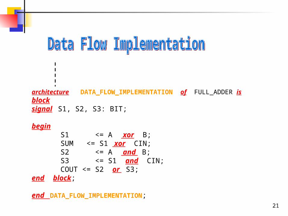
architecture DATA_FLOW_IMPLEMENTATION of FULL_ADDER isblocksignal S1, S2, S3: BIT;
beginS1 <= A xor B;SUM <= S1 xor CIN;S2 <= A and B;S3 <= S1 and CIN;COUT <= S2 or S3;
end block;
end DATA_FLOW_IMPLEMENTATION;
22
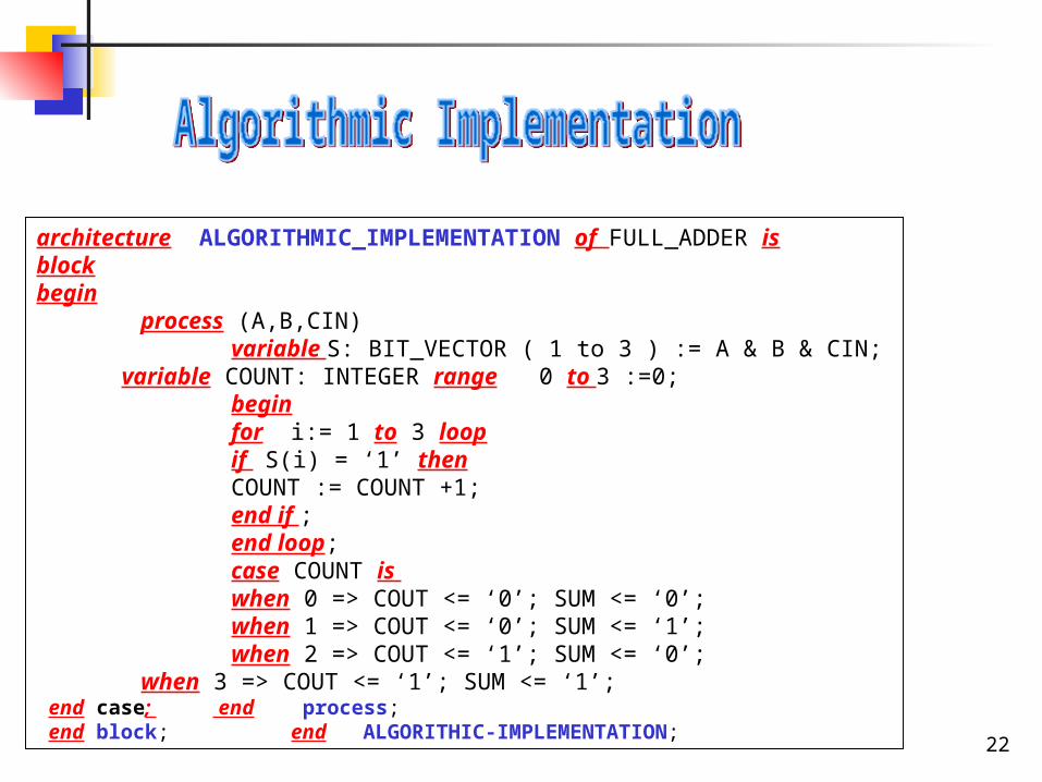
architecture ALGORITHMIC_IMPLEMENTATION of FULL_ADDER isblockbegin
process (A,B,CIN) variable S: BIT_VECTOR ( 1 to 3 ) := A & B & CIN; variable COUNT: INTEGER range 0 to 3 :=0; begin for i:= 1 to 3 loop if S(i) = ‘1’ then COUNT := COUNT +1; end if ; end loop; case COUNT is when 0 => COUT <= ‘0’; SUM <= ‘0’; when 1 => COUT <= ‘0’; SUM <= ‘1’; when 2 => COUT <= ‘1’; SUM <= ‘0’;
when 3 => COUT <= ‘1’; SUM <= ‘1’; end case; end process; end block; end ALGORITHIC-IMPLEMENTATION;
23
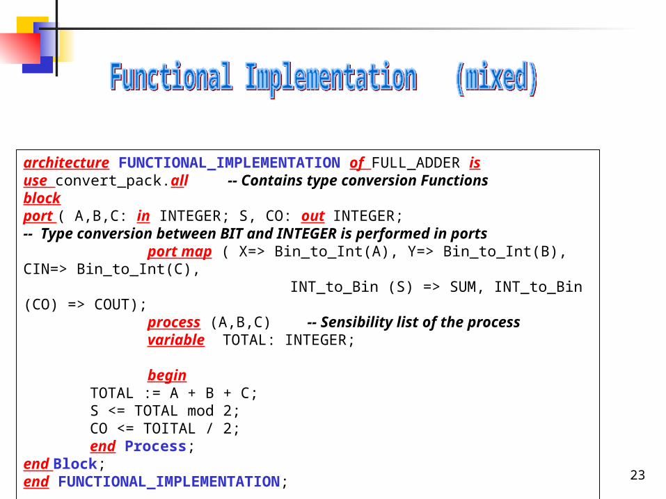
architecture FUNCTIONAL_IMPLEMENTATION of FULL_ADDER isuse convert_pack.all -- Contains type conversion Functionsblockport ( A,B,C: in INTEGER; S, CO: out INTEGER; -- Type conversion between BIT and INTEGER is performed in ports port map ( X=> Bin_to_Int(A), Y=> Bin_to_Int(B), CIN=> Bin_to_Int(C), INT_to_Bin (S) => SUM, INT_to_Bin (CO) => COUT); process (A,B,C) -- Sensibility list of the process variable TOTAL: INTEGER; begin
TOTAL := A + B + C;S <= TOTAL mod 2;CO <= TOITAL / 2;end Process;
end Block;end FUNCTIONAL_IMPLEMENTATION;

24
architecture MIXED_IMPLEMENTATION of FULL_ADDER is
signal WIRE: BIT; component XOR_Gport ( X1, X2: in BIT; XO1: out BIT);end component; for all: XOR_G use XOR_GATE(BEHAVIORAL);
-- Selection of Component Bodiesbegin
XOR1: XOR_G port map (X,Y,WIRE);XOR2: XOR_G port map (WIRE,CIN,SUM);COUT <= (WIRE and CIN) or (X and Y);
end MIXED_IMPLEMENTATION ;
SRUCTURAL
Data Flow
25
THERE ARE VARIOUS SITES THAT YOU MAY TRY TO GET VHDl
http://www.freedownloadscenter.com/Best/vhdl-tool-free.html
http://www.csee.umbc.edu/help/VHDL/#free
ActiveHDL
http://www.aldec.com/products/active-hdl/ Please visit this site for window based VHDL they have a demo that you can be downloaded The tool is called
ActiveHDL.
Xilinx:
www.xilinx.com/ise/logic_design_prod/webpack.htm
VHDL Simili
http://www.symphonyeda.com/products.htm. There's a free version for students, but you can only simulate 10 waveforms at the same time. There is also a 30 day trial for the standard/professional edition which does not have this limit. It is very good and
Aldec's Active-HDL EDA tool and free educational resources
http://www.aldec.com/downloads
26
Environmental Set Up for Synopsys VHDL Analyzer/Simulator
For information on how to set up your environment for the VHDL simulator please go to the following website:
http://www.encs.concordia.ca/helpdesk/resource/manuals_tutorials/tutorial.pdf
27
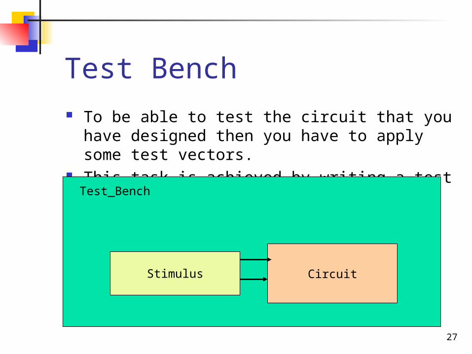
Test Bench To be able to test the circuit that you have
designed then you have to apply some test vectors.
This task is achieved by writing a test bench.Test_Bench
CircuitStimulus
28
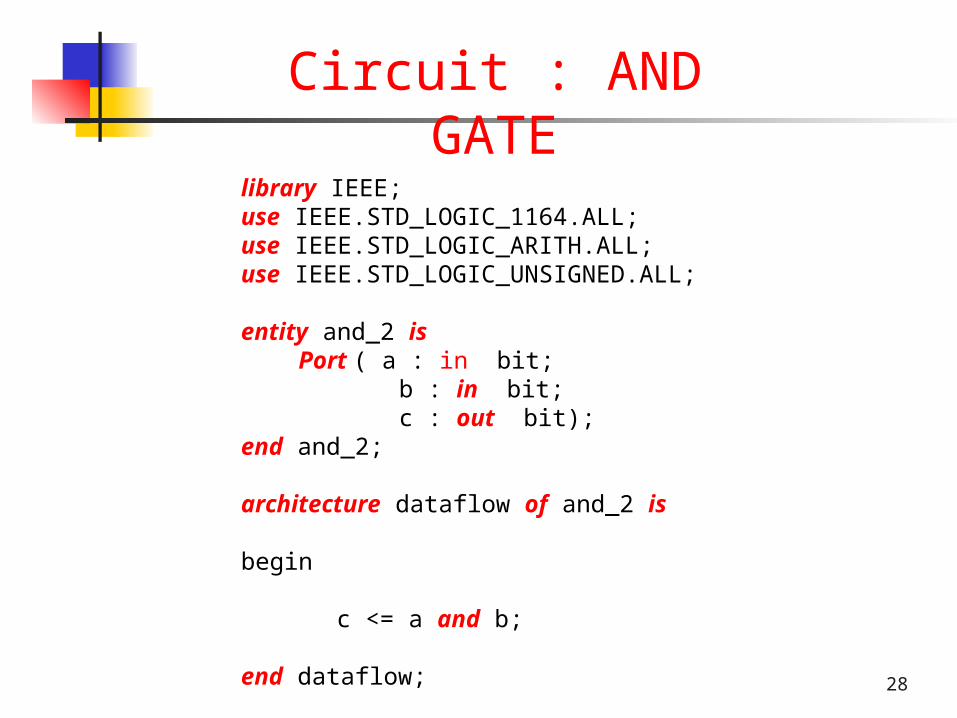
library IEEE;use IEEE.STD_LOGIC_1164.ALL;use IEEE.STD_LOGIC_ARITH.ALL;use IEEE.STD_LOGIC_UNSIGNED.ALL;
entity and_2 is Port ( a : in bit; b : in bit; c : out bit);end and_2;
architecture dataflow of and_2 is
begin
c <= a and b;
end dataflow;
Circuit : AND GATE
29
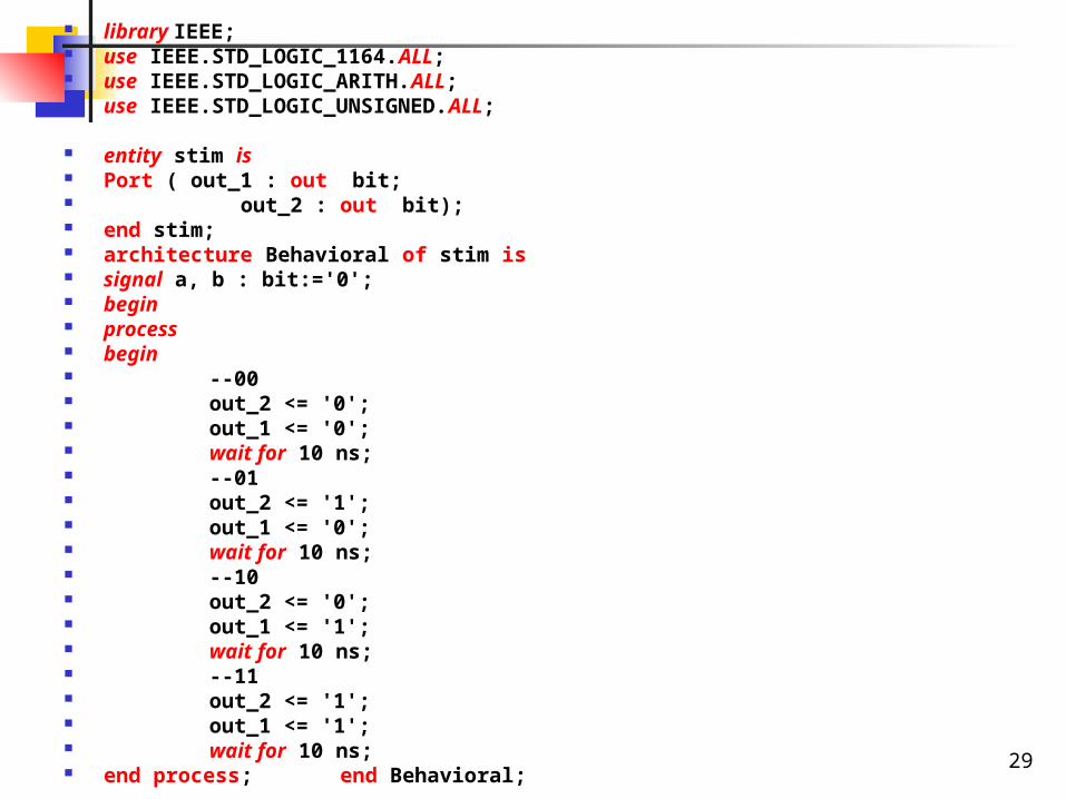
library IEEE; use IEEE.STD_LOGIC_1164.ALL; use IEEE.STD_LOGIC_ARITH.ALL; use IEEE.STD_LOGIC_UNSIGNED.ALL;
entity stim is Port ( out_1 : out bit; out_2 : out bit); end stim; architecture Behavioral of stim is signal a, b : bit:='0'; begin process begin --00 out_2 <= '0'; out_1 <= '0'; wait for 10 ns; --01 out_2 <= '1'; out_1 <= '0'; wait for 10 ns; --10 out_2 <= '0'; out_1 <= '1'; wait for 10 ns; --11 out_2 <= '1'; out_1 <= '1'; wait for 10 ns; end process; end Behavioral;
30
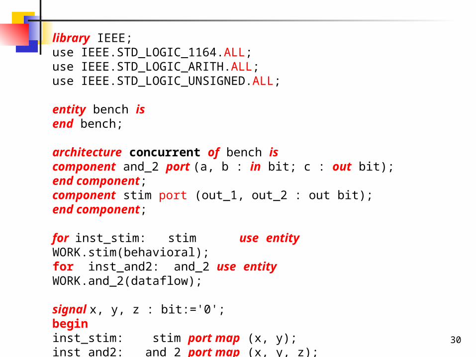
library IEEE;use IEEE.STD_LOGIC_1164.ALL;use IEEE.STD_LOGIC_ARITH.ALL;use IEEE.STD_LOGIC_UNSIGNED.ALL;
entity bench isend bench;
architecture concurrent of bench iscomponent and_2 port (a, b : in bit; c : out bit);end component; component stim port (out_1, out_2 : out bit);end component;
for inst_stim: stim use entity WORK.stim(behavioral);for inst_and2: and_2 use entity WORK.and_2(dataflow);
signal x, y, z : bit:='0';begininst_stim: stim port map (x, y);inst_and2: and_2 port map (x, y, z);end concurrent ;
31
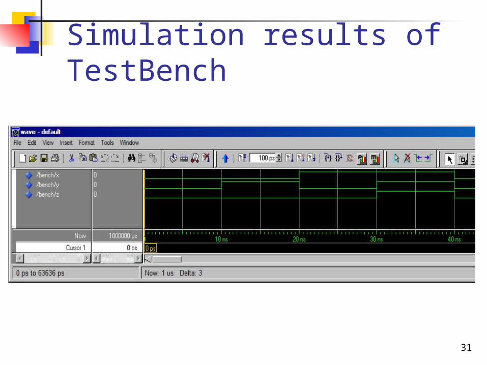
Simulation results of TestBench