1 Combinational Logic Lecture #8. Combinational Logic 2 Combination Logic - 강의순서 Decoder...
44
1 Combinational Logic Combinational Logic Lecture #8 Lecture #8
-
Upload
shanon-waters -
Category
Documents
-
view
226 -
download
3
Transcript of 1 Combinational Logic Lecture #8. Combinational Logic 2 Combination Logic - 강의순서 Decoder...

1
Combinational LogicCombinational Logic
Lecture #8Lecture #8

Combinational Logic 2
Combination Logic - Combination Logic - 강의순서강의순서
Decoder 3x8 Process – Case Statement
Mux 4x1 Signal Assignment, Conditional Signal Assignment, Selected Process – if Statement Process – Case Statement
Mux 8x1 Mixed Modeling Process – Case Statement
Mux 8x1 4bits Process – Case Statement, Constants 이용 Signal Assignment, Selected
4 bits Adder

Combinational Logic 3
Combination LogicCombination Logic – Decoder 3x8 – Decoder 3x8 (CASE)(CASE)
library ieee; use ieee.std_logic_1164.all;entity decoder38_proc is port( d2, d1, d0 : in std_logic; y0,y1,y2,y3,y4,y5,y6,y7 : out std_logic);end decoder38_proc;architecture xxx of decoder38_proc issignal d : std_logic_vector(2 downto 0);signal t : std_logic_vector( 0 to 7);begin d <= d2&d1&d0; process(d) begin case d is
when "000" => t<="10000000";when "001" => t<="01000000";when "010" => t<="00100000";when "011" => t<="00010000";when "100" => t<="00001000";when "101" => t<="00000100";when "110" => t<="00000010";when others => t<="00000001";
end case; end process; y0 <= t(0); y1 <= t(1); y2 <= t(2); y3 <= t(3); y4 <= t(4); y5 <= t(5); y6 <= t(6); y7 <= t(7);end xxx;
d(2) <= d2;d(1) <= d1;d(0) <= d0;
같은 표현같은 표현
회로보다는 설계사양에 관심을 둔
설계방식 .
회로보다는 설계사양에 관심을 둔
설계방식 .

Combinational Logic 4
Combination LogicCombination Logic – Decoder 3x8 – Decoder 3x8 (CASE)(CASE)
Timing Simulation Result

Combinational Logic 5
Combination Logic – Mux Combination Logic – Mux 4x1 4x1 (Signal Assignment, Conditional)(Signal Assignment, Conditional)
library ieee;use ieee.std_logic_1164.all;
entity mux41_ when is port( a, b, c, d: in std_logic; s : in std_logic_vector(1 downto 0); y : out std_logic);end mux41_ when;
architecture a of mux41_when isBEGIN y <= a when (s=“00”) else b when (s=“01”) else c when (s=“10”) else d;END a;
Combinational Logic 6
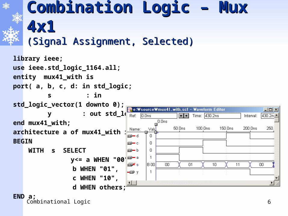
Combination Logic – Mux Combination Logic – Mux 4x1 4x1 (Signal Assignment, Selected)(Signal Assignment, Selected)
library ieee;
use ieee.std_logic_1164.all;
entity mux41_with is
port( a, b, c, d: in std_logic;
s : in std_logic_vector(1 downto 0);
y : out std_logic);
end mux41_with;
architecture a of mux41_with is
BEGIN
WITH s SELECT
y<= a WHEN "00",
b WHEN "01",
c WHEN "10",
d WHEN others;
END a;
Combinational Logic 7
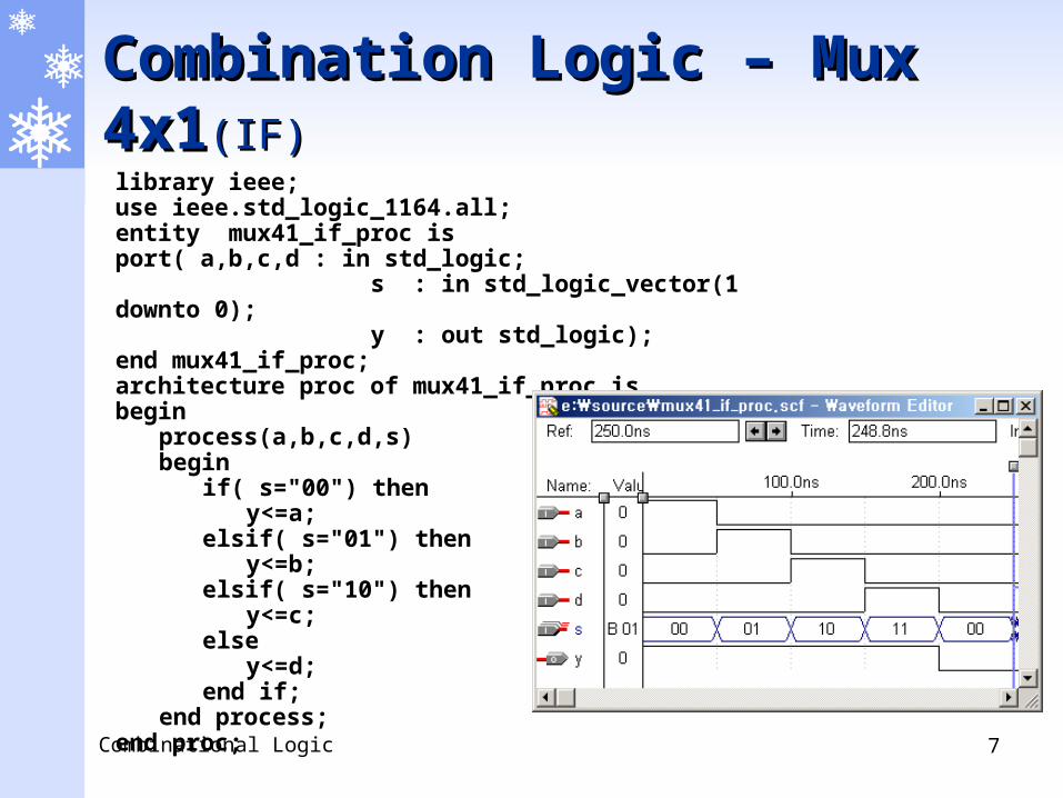
Combination Logic – Mux Combination Logic – Mux 4x14x1(IF)(IF)library ieee;use ieee.std_logic_1164.all;entity mux41_if_proc is port( a,b,c,d : in std_logic; s : in std_logic_vector(1 downto 0); y : out std_logic);end mux41_if_proc;architecture proc of mux41_if_proc isbegin
process(a,b,c,d,s)begin
if( s="00") theny<=a;
elsif( s="01") theny<=b;
elsif( s="10") theny<=c;
elsey<=d;
end if;end process;
end proc;

Combinational Logic 8
Combination Logic – Mux Combination Logic – Mux 4x14x1(CASE)(CASE)
library ieee;use ieee.std_logic_1164.all;entity mux41_case_proc is port( a,b,c,d : in std_logic; s : in std_logic_vector(1 downto 0); y : out std_logic);end mux41_case_proc;architecture proc of mux41_case_proc isbegin process(a,b,c,d,s) begin case s is when "00" => y<=a;
when "01" => y<=b;when "10" => y<=c;when others => y<=d;
end case; end process;end proc;

Combinational Logic 9
Combination Logic - Combination Logic - Mux Mux 8X1 8X1 ( Mixed Modeling)( Mixed Modeling)Library ieee; Use ieee.std_logic_1164.all;
entity mux8_1 is
port( a, b, c, d, e, f, g, h : in std_logic;
s2, s1, s0 : in std_logic;
y : out std_logic);
end mux8_1;
architecture xxx of mux8_1 is
component decoder3_8
port( a, b, c : in std_logic;
d0,d1,d2,d3,d4,d5,d6,d7 : out std_logic);
end component;
signal t : std_logic_vector(7 downto 0);
signal d0,d1,d2,d3,d4,d5,d6,d7 : std_logic;
begin
U1: decoder3_8 port map( s2,s1,s0,d0,d1,d2,d3,d4,d5,d6,d7);
t(0) <= a and d0; t(1) <= b and d1; t(2) <= c and d2;
t(3) <= d and d3; t(4) <= e and d4; t(5) <= f and d5;
t(6) <= g and d6; t(7) <= h and d7;
y <= t(0) or t(1) or t(2) or t(3) or t(4) or t(5) or t(6) or t(7);
end xxx;
t(0)
t(1)
t(2)
t(3)
t(4)
t(5)
t(6)
t(7)
Decoder3_8.vhd 는 미리 작성된 상태임
Decoder3_8.vhd 는 미리 작성된 상태임
Mixed Modeling : structure +
dataflow

Combinational Logic 10
Combination Logic – Mux Combination Logic – Mux 8X1 8X1 (Constants)(Constants)library ieee; use ieee.std_logic_1164.all;
entity mux8_1_proc is port( a,b,c,d,e,f,g,h : in std_logic;
s2, s1, s0 : in std_logic; y : out std_logic);
end mux8_1_proc;architecture proc of mux8_1_proc isconstant bits3_0 : std_logic_vector(2 downto 0) := "000";constant bits3_1 : std_logic_vector(2 downto 0) := "001";constant bits3_2 : std_logic_vector(2 downto 0) := "010";constant bits3_3 : std_logic_vector(2 downto 0) := "011";constant bits3_4 : std_logic_vector(2 downto 0) := "100";constant bits3_5 : std_logic_vector(2 downto 0) := "101";constant bits3_6 : std_logic_vector(2 downto 0) := "110";constant bits3_7 : std_logic_vector(2 downto 0) := "111";begin
process(a,b,c,d,e,f,g,h,s2,s1,s0)variable sel : std_logic_vector(2 downto 0);begin
sel := s2 & s1 & s0;case sel is
when bits3_0 => y<= a;when bits3_1 => y<= b;when bits3_2 => y<= c;when bits3_3 => y<= d;when bits3_4 => y<= e;when bits3_5 => y<= f;when bits3_6 => y<= g;when others => y<= h;
end case;end process;
end proc;
sel(2) := s2;sel(1) := s1;sel(0) := s0;
같은 표현
같은 표현

Combinational Logic 11
Combination Logic – Mux 8x1 Combination Logic – Mux 8x1 4bits 4bits (Signal Assignment, (Signal Assignment, Selected)Selected)
library ieee;use ieee.std_logic_1164.all;
entity mux81_4bits_with is port( a, b, c, d, e, f, g, h : in
std_logic_vector(3 downto 0); s2, s1, s0 : in std_logic; y : out std_logic_vector(3 downto 0));end mux81_4bits_with;
architecture a of mux81_4bits_with issignal s : std_logic_vector(2 downto 0);BEGIN s <= s2 & s1 & s0; -- s(2)<=s2; s(1)<=s1;s(0)<=s0;
WITH s SELECT y <= a WHEN "000",
b WHEN "001", c WHEN "010", d WHEN "011", e WHEN "100",
f WHEN "101", g WHEN "110",
h WHEN others;END a;
Combinational Logic 12
Combination Logic – Mux 8x1 Combination Logic – Mux 8x1 4bits4bits (CASE)(CASE)
library ieee; use ieee.std_logic_1164.all;
entity mux81_4bits_proc is port( a,b,c,d,e,f,g,h : in std_logic_vector(3 downto 0);
s2, s1, s0 : in std_logic; y : out std_logic_vector(3 downto 0));
end mux81_4bits_proc;
architecture proc of mux81_4bits_proc issignal sel : std_logic_vector(2 downto 0);begin
sel <= s2 & s1 & s0;process(a,b,c,d,e,f,g,h,sel)begin
case sel iswhen "000" => y<= a;when "001" => y<= b;when "010" => y<= c;when "011" => y<= d;when "100" => y<= e;when "101" => y<= f;when "110" => y<= g;when others => y<= h;
end case;end process;
end proc;

Combinational Logic 13
Combination Logic – 4 bits Combination Logic – 4 bits Adder Adder
library ieee;use ieee.std_logic_1164.all;use ieee.std_logic_unsigned.all;
entity add_4bits_proc is port( a, b : in std_logic_vector(3 downto 0); s : out std_logic_vector(3 downto 0));end add_4bits_proc;
architecture a of add_4bits_proc isbegin
s <= a+b;end a;
+ 연산자가 사용될 때 꼭 사용 .
+ 연산자가 사용될 때 꼭 사용 .

14
PXA255-FPGAPXA255-FPGA
실습장비 PXA255-FPGA 에 대한 개요 및 예제 실습

Combinational Logic 15
내용 순서내용 순서 PXA255-FPGA BLOCK DIAGRAM PXA255-FPGA SPEC PXA255-FPGA 사용 방법 PXA255-FPGA 예제 실습 (LED)

Combinational Logic 16
PXA255-FPGA BLOCK PXA255-FPGA BLOCK DIAGRAMDIAGRAM

Combinational Logic 17
PXA255-FPGA SPECPXA255-FPGA SPEC PXA255-FPGA BOARD 사양
FPGA Altera cyclone EP1C6
LOGIC ELEMENTS 5980
LOGIC GATE 120000 Logic Gate
RAM BIT 92160 Bit
외부 CPU PXA255
외부 INTERFACE 32 BIT address/data bus
입력 I/O PUSH S/W, DIP S/W, IMAGE SENSOR
출력 I/O TEXT LCD, LED, 7SEGMENT, BUZZER, DOTMATRIX, VGA

Combinational Logic 18
VGA
TEXT-LCD
I/O 100PIN
FPGA
JTAG PORT
AD/DA PORT
PUSH S/W
LED EXTERN I/OSTEP MOTOR
CAMERA CONN
DOT
BUZZER
DIP S/W
7-SEG DIP S/W

Combinational Logic 19
PXA255-FPGA PXA255-FPGA 동작방법 동작방법 (1)(1) PXA255-PRO 보드와 PXA255-FPGA 보드와의 연동방법
PXA255Main Board
FPGA
I/O 주변장치LED,FND,DOT MATRIX,LCD,
7-SEG,BUZZER,CAMERA,MOTOR,SENSOR( 온도 , 기울기 , 조도 )
AD
DR
ES
S B
US
CO
NTO
RL
SIG
NA
L
DA
TA
BU
S
PXA255-FPGA4 보드
Combinational Logic 20
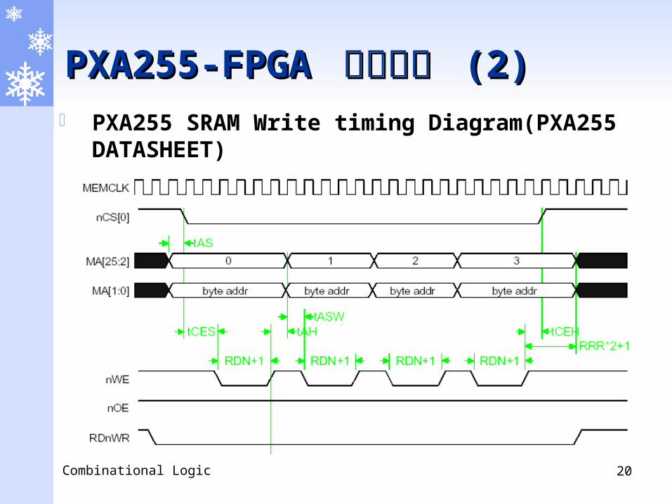
PXA255-FPGA PXA255-FPGA 동작방법 동작방법 (2)(2) PXA255 SRAM Write timing Diagram(PXA255
DATASHEET)

Combinational Logic 21
PXA255-FPGA PXA255-FPGA 동작방법 동작방법 (3)(3)
PXA255 memory map

Combinational Logic 22
PXA255-FPGA PXA255-FPGA 동작방법 동작방법 (4)(4) 디바이스 메모리맵 :

Combinational Logic 23
PXA255-FPGA PXA255-FPGA 동작방법 동작방법 (5)(5)
PXA255-FPGA 보드 단독 동작 모드
FPGA
I/O 주변장치LED,FND,DOT MATRIX,LCD,
7-SEG,BUZZER,CAMERA,MOTOR,SENSOR( 온도 , 기울기 , 조도 )
PXA255-FPGA4 보드POWER JACK

Combinational Logic 24
PXA255-FPGA PXA255-FPGA 동작방법 동작방법 (6)(6) DIP SW 을 이용한 동작 모드 선택
PXA255-PRO 보드와 PXA255-FPGA 보드와의 연동 방법
PXA255-FPGA 보드 단독 동작 모드
ON 1 2
ON 1 2

Combinational Logic 25
PXA255-FPGA PXA255-FPGA 예제 프로그램예제 프로그램(LED)(LED)
개요 PXA255-FPGA 를 이용하여 LED 에 대한 동작을 이해하고
디바이스 드라이버를 작성하여 LED 를 제어 한다
system 요구사항 Hardware 요구사항
PXA255-PRO PXA255-FPGA ByteBlaster Interface Cable
Software 요구사항 Quartus II V2.2 이상
사용 Hardware Description Language VHDL

Combinational Logic 26
PXA255-FPGA PXA255-FPGA 예제 프로그램예제 프로그램(LED)(LED)
FPGA - LED 회로도 구성

Combinational Logic 27
PXA255-FPGA PXA255-FPGA 예제 프로그램예제 프로그램(LED)(LED)

Combinational Logic 28
Quartus II Project Quartus II Project 파일 생성 파일 생성 (1)(1) New Project Wizard 를
통한 Quartus Project 생성하기 File 메뉴에서 New Proj
ect Wizard 를 실행하여 새로운 프로젝트를 만들어보자 .

Combinational Logic 29
Quartus II Project Quartus II Project 파일 생성 파일 생성 (2)(2) New Project Wizard ①
Project 를 설치할 경로 와 프로젝트의 이름과 top-level entity 이름을 지정하는 부분이 있다

Combinational Logic 30
Quartus II Project Quartus II Project 파일 생성 파일 생성 (3)(3) New Project Wizard ②
오른쪽의 그림은 다음 단계인 설계된 파일이 있으면 추가 하는 단계
추가할 파일이 프로젝트 디렉토리에 있다면 [ADD ALL] 버튼을 클릭하면 모두 추가
[...] 버튼을 클릭하여 그림과 같이 4 개의 파일을 추가
[Next] 버튼을 눌러 다음 설정으로 이동

Combinational Logic 31
Quartus II Project Quartus II Project 파일 생성 파일 생성 (4)(4) New Project Wizard ③
EDA Tool 에 대한 설정을 하는 부분 Thirth party EDA tool 을 사용한다면 설정하고 , 사용하지
않는다면 [Next] 버튼을 눌러 다음 설정으로 이동

Combinational Logic 32
Quartus II Project Quartus II Project 파일 생성 파일 생성 (5)(5) New Project Wizard ④
Device Family 를 설정하는 부분 PXA255-FPGA 보드는 Cyclone 을 사용하고 있으므로 Cyclone
으로 설정

Combinational Logic 33
Quartus II Project Quartus II Project 파일 생성 파일 생성 (6)(6) New Project Wizard ⑤
PXA255-FPGA 에는 EP1C12Q240C8 을 사용하고 있으므로 해당 Device 를 선택
오른쪽 메뉴의 Filter 사용 하면 쉽게 선택할 수 있다

Combinational Logic 34
Quartus II Project Quartus II Project 파일 생성 파일 생성 (7)(7) New Project Wizard ⑥
지금까지 설정을 확인하는 단계 프로젝트경로와 프로젝트 이름 , top-level design entity 이름 ,
추가한 파일의 개수를 확인
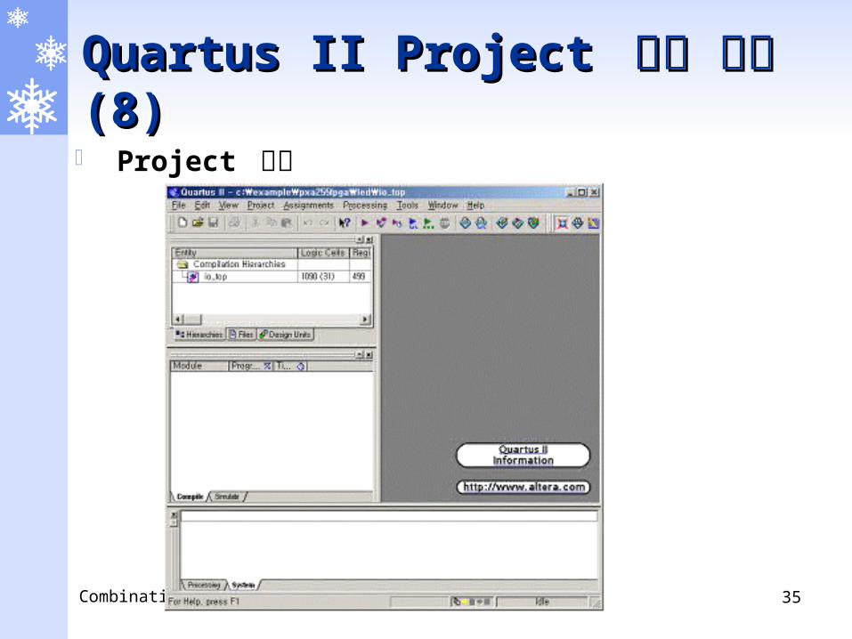
Combinational Logic 35
Quartus II Project Quartus II Project 파일 생성 파일 생성 (8)(8) Project 생성

Combinational Logic 36
Quartus II Project Quartus II Project 파일 생성 파일 생성 (9)(9) Pin Assignment
Pin Assign File 수정 - io_top.csf 파일을 열어서 옆 그림과 같이 CHIP (io_top) 섹션에 핀 매핑에 대한 정보를 수정
Quartus II 에는 핀을 매핑 할 수 있는 별도의 메뉴가 존재하지만 io_top.csf 파일을 수정하면 보다 손쉽게 매핑 할 수 있다
CHIP(io_top) { LED[0] : LOCATION = Pin_1; LED[1] : LOCATION = Pin_2; LED[2] : LOCATION = Pin_3; LED[3] : LOCATION = Pin_4; LED[4] : LOCATION = Pin_5; LED[5] : LOCATION = Pin_6; LED[6] : LOCATION = Pin_7; LED[7] : LOCATION = Pin_8; MAIN_CLK1 : LOCATION = Pin_29; ...... 이하 계속 .......

Combinational Logic 37
Quartus II Project Quartus II Project 파일 생성 파일 생성 (10)(10) 사용하지 않는 핀들에 대한 설정
Device 설정 창에서 Device & Pin Options 을 선택

Combinational Logic 38
Quartus II Project Quartus II Project 파일 생성 파일 생성 (11)(11) Unused Pin 에 대한 설정
Reserve all unused pins 에서 As Input, tri stated 를 선택 외부에 아무런 영향을 주지 않기 위함

Combinational Logic 39
Quartus II Project Quartus II Project 파일 생성 파일 생성 (12)(12) Configuration 에 대한 설정
그림과 같이 Configuration scheme 와 device 를 설정

Combinational Logic 40
Quartus II Project Quartus II Project 파일 생성 파일 생성 (13)(13) 기타 설정
General 탭에서 Auto-restart configuration after error 을 선택 FPGA 에서 에러가 발생하면 자동으로 다시 Configuration 하게
설정

Combinational Logic 41
Quartus II Project Quartus II Project 파일 생성 파일 생성 (14)(14) Compilation
지금까지의 설정이 정상적으로 이루어졌다면 Processing 메뉴에서 Start Compilation 을 실행
컴파일이 완료되면 ‘ Full compilation was successful‘ 이라는 메시지를 보여주며 컴파일이 끝나게 된다

Combinational Logic 42
Quartus II Project Quartus II Project 파일 생성 파일 생성 (15)(15) Configuration
지금까지의 과정이 모두 끝났다면 FPGA 로 Configuration 을 하여야 한다
Programmer 실행 - EPC2 에 다운로드 하거나 FPGA 에 Configuration 하기 위해서 Programmer 를 실행

Combinational Logic 43
Quartus II Project Quartus II Project 파일 생성 파일 생성 (16)(16) Configuration 파일 불러오기
Byteblaster 케이블이 JTAG 포트에 연결된 상태에서 [Auto Detect] 를 하면 EPC2 와 EP1C6 두 개의 장치를 검출
<none> 를 더블 클릭하여 EPC2 에는 io_top.pof 파일을 , EP1C6 에는 io_top.sof 파일을 설정한다

Combinational Logic 44
Quartus II Project Quartus II Project 파일 생성 파일 생성 (17)(17) Configuration
Program/Configure 에 체크 옵션에 체크를 한다 [Start] 버튼을 클릭하면 체크한 항목에 대해서만 Download 및
Configuration 을 수행한다 [Start] 버튼을 클릭하여 실행한다 .