1 CIRCE Polarimetry - Gran Telescopio CANARIAS · CIRCE+GTC Polarimetry Commissioning Report 1...
15
0 ◦ ∼ ∼ K s H J 0 ◦ 45 ◦ 22.5 ◦ 67.5 ◦ 0 ◦ 45 ◦ 0 ◦ ↑ → % & 45 ◦ → ↑ & % 22.5 ◦ % & ↑ → 67.5 ◦ & % → ↑ http://adsabs.harvard.edu/abs/2008SPIE.7014E..2MC
-
Upload
hoangthien -
Category
Documents
-
view
228 -
download
0
Transcript of 1 CIRCE Polarimetry - Gran Telescopio CANARIAS · CIRCE+GTC Polarimetry Commissioning Report 1...

CIRCE+GTC Polarimetry Commissioning Report
1 CIRCE Polarimetry
The polarimetry mode of CIRCE provides measurement of the linear Stokes parameters in asingle image, unlike standard dual-beam polarimeters. This is achieved with a wedged doublewollaston (WeDoWo) (Charcos-Llorens, 2008)1 implementation, in which the fast axis of one ofthe wollaston prisms is rotated 22.5 degrees and the same prism is tilted enough to separate twoorthogonal pairs of sub-images. This design is the main strength of CIRCE polarimetry modesince fast polarimetric variability of interesting astrophysical sources can be investigated withsimultaneous measurement of the q and u parameters. In addition, only two half wave plate(HWP) rotations can be used instead of all four to signi�cantly reduce calibration/observingtime.
Figure 1: An example of a polarimetry data acquisition image with CIRCE, HWP at 0◦.
Sub-images of four directional polarizations are aligned in the horizontal direction and eachhave a size about ∼110x110 pixels (or ∼11�x11�). Therefore, fast band readouts as narrow as130 pixels can be used without losing any information in the �eld of view. The minimum inte-gration time of these fast readouts is about 100 miliseconds. These readouts can be exploitedfor the purposes of fast data acquisition or observations of very bright targets without non-linearity/saturation. The lack of dim polarized/null standards is known to be a problem forimaging polarimetry with large telescopes, but CIRCE can o�er observations of point sourcesas bright as 7th magnitude in Ks and H �lters, or about 5th magnitude in J �lter, even underexcellent seeing conditions (about 0.5 arcsecond). Observations of brighter targets than theselimits are still an option but should be discussed with UF CIRCE team.
There are four default rotation for the half-wave plate (HWP) of CIRCE. One of the orthogonalpairs, either (0◦, 45◦) or (22.5◦, 67.5◦), is su�cient to fully de�ne the polarization state of apoint source. The polarization directions of the four sub-images with respect HWP rotationsare given in Table 1. We currently o�er (0◦, 45◦) pair as the default.
HWP o1 e1 o2 e20◦ ↑ → ↗ ↘45◦ → ↑ ↘ ↗
22.5◦ ↗ ↘ ↑ →67.5◦ ↘ ↗ → ↑
Table 1: Polarization information of sub-images with respect to HWP angle.
1http://adsabs.harvard.edu/abs/2008SPIE.7014E..2MC
1

With this con�guration, q and u measurements can be obtained with the following equations,
q(0◦/45◦) =
√o1(0◦)e1(45◦)−
√o1(45◦)e1(0◦)√
o1(0◦)e1(45◦) +√o1(45◦)e1(0◦)
(1)
u(0◦/45◦) =
√o2(0◦)e2(45◦)−
√o2(45◦)e2(0◦)√
o2(0◦)e2(45◦) +√o2(45◦)e2(0◦)
(2)
q(22.5◦/67.5◦) =
√o1(22.5◦)e1(67.5◦)−
√o1(67.5◦)e1(22.5◦)√
o1(22.5◦)e1(67.5◦) +√o1(67.5◦)e1(22.5◦)
(3)
u(22.5◦/67.5◦) =
√o2(22.5◦)e2(67.5◦)−
√o2(67.5◦)e2(22.5◦)√
o2(22.5◦)e2(67.5◦) +√o2(67.5◦)e2(22.5◦)
(4)
2 Observing Procedure and Calibrations
2.1 Standard Observing Procedure
Once per night before observing, we suggest a datum of the linear slide and HWP mechanisms.CIRCE should be focused before slewing to a target for polarimetry observations. The standardpolarimetry observing procedure of a target is given below:
1. Slew to the target and acquire a single frame image.
2. Move the target to the desired polarimetry location in the frame.
(or click �Polarimetry O�set� button)
3. Move the grism wheel to WOLLY and the linear slide to FULL_F_IMAGING position.
4. Acquire a single frame image. Target should be well-centered in four sub-images.
If not, do a manual o�set and take another image to con�rm. Repeat if necessary.
5. Switch to band mode and set necessary detector parameters.
(This should be included in the XML �le. What it needs to do: switch from full frameto band mode, set to a default start and end row that we determine)
6. Start the observing sequence.
7. While the sequence is active, keep checking images for each dither(!!).
8. Switch to full frame and set necessary detector parameters.
9. Move the grism wheel to OPEN and linear slide to RETRACTED position.
2.2 Observing Sequences
The single dither position observing time should be at least 20 seconds for e�ective use oftelescope time (for > 50% duty cycle) and not more than 35-40 seconds due to the variableinfrared sky (up to 60 seconds for J �lter). The only option for bright targets (< 9 mag forKs and H, < 8 mag for J) is a con�guration of 100 ramps each with 100 ms exposure time.Fainter targets can be observed with the con�guration of 30 ramps each with 1 s exposure
2
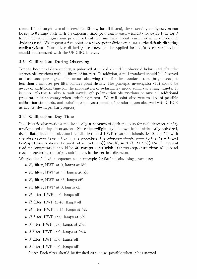
time. If faint targets are of interest (> 12 mag for all �lters), the observing con�guration canbe set to 6 ramps each with 5 s exposure time (or 6 ramps each with 10 s exposure time for J�lter). These con�gurations provide a total exposure time about 5 minutes when a �ve-pointdither is used. We suggest a �ve-point or a three-point dither on a line as the default ditheringcon�gurations. Customized dithering sequences can be applied for special requirements butshould be discussed with the UF CIRCE team.
2.3 Calibration: During Observing
For the best �nal data quality, a polarized standard should be observed before and after thescience observations with all �lters of interest. In addition, a null standard should be observedat least once per night. The actual observing time for the standard stars (bright ones) isless than 6 minutes per �lter for �ve-point dither. The principal investigator (PI) should beaware of additional time for the preparation of polarimetry mode when switching targets. Itis more e�ective to obtain multiwavelength polarization observations because no additionalpreparation is necessary when switching �lters. We will point observers to lists of possiblecalibration standards, and polarimetric measurements of standard stars observed with CIRCEas the list develops. (In progress)
2.4 Calibration: Day Time
Polarimetric observations require ideally 9 repeats of dark readouts for each detector con�g-uration used during observations. Since the twilight sky is known to be intrinsically polarized,dome �ats should be obtained at all �lters and HWP rotations (should be 0 and 45) withthe observations taken. During the procedure, the telescope should point to the Zenith andGroup 1 lamps should be used, at a level of 5% for Ks and H, at 25% for J . Typicalreadout con�guration should be 30 ramps each with 100 ms exposure time while bandreadout centering the bright sub-images in the vertical direction.
We give the following sequence as an example for �at�eld obtaining procedure;
• Ks �lter, HWP at 0, lamps at 5%
• Ks �lter, HWP at 45, lamps at 5%
• Ks �lter, HWP at 45, lamps o�
• Ks �lter, HWP at 0, lamps o�
• H �lter, HWP at 0, lamps o�
• H �lter, HWP at 45, lamps o�
• H �lter, HWP at 45, lamps at 5%
• H �lter, HWP at 0, lamps at 5%
• J �lter, HWP at 0, lamps at 25%
• J �lter, HWP at 0, lamps at 25%
• J �lter, HWP at 0, lamps o�
• J �lter, HWP at 0, lamps o�
Note: Each �lter should be �nished as soon as possible when it has started.
3
2.5 Data Reduction
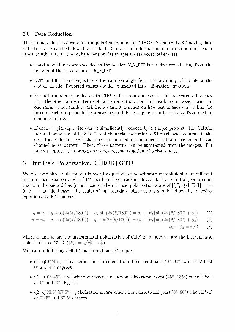
There is no default software for the polarimetry mode of CIRCE. Standard NIR imaging datareduction steps can be followed as a default. Some useful information for data reduction (headerrefers to 0th HDU in the multi extension �ts images unless noted otherwise):
• Band mode limits are speci�ed in the header. W_Y_BEG is the �rst row starting from thebottom of the detector up to W_Y_END
• ROT1 and ROT2 are respectively the rotation angle from the beginning of the �le to theend of the �le. Reported values should be inserted into calibration equations.
• For full frame imaging data with CIRCE, �rst ramp images should be treated di�erentlythan the other ramps in terms of dark subtraction. For band readouts, it takes more thanone ramp to get similar dark frames and it depends on how fast images were taken. Tobe safe, each ramp should be treated separately. Bad pixels can be detected from mediancombined darks.
• If desired, pick-up noise can be signi�cantly reduced by a simple process. The CIRCEinfrared array is read by 32 di�erent channels, each refer to 64 pixels wide columns in thedetector. Odd and even channels can be median combined to obtain master odd/evenchannel noise pattern. Then, these patterns can be subtracted from the images. Formany purposes, this process provides decent reduction of pick-up noise.
3 Intrinsic Polarization: CIRCE+GTC
We observed three null standards over two periods of polarimetry commissioning at di�erentinstrumental position angles (IPA) with rotator tracking disabled. By de�nition, we assumethat a null standard has (or is close to) the intrinsic polarization state of [I/I, Q/I, U/I] = [1,0, 0]. In an ideal case, rthe esults of null standard observations should follow the followingequations as IPA changes:
q = qc + qT cos(2π(θ/180◦))− uT sin(2π(θ/180◦)) = qc + |PT | sin(2π(θ/180◦) + φ1) (5)
u = uc − uT cos(2π(θ/180◦))− qT sin(2π(θ/180◦)) = uc + |PT | sin(2π(θ/180◦) + φ2) (6)
φ1 − φ2 = π/2 (7)
where qc and uc are the instrumental polarization of CIRCE, qT and uT are the instrumentalpolarization of GTC. (|PT | =
√q2T + u2T )
We use the following de�nitions throughout this report:
• q1: q(0◦/45◦) - polarization measurement from directional pairs (0◦, 90◦) when HWP at0◦ and 45◦ degrees
• u1: u(0◦/45◦) - polarization measurement from directional pairs (45◦, 135◦) when HWPat 0◦ and 45◦ degrees
• q2: q(22.5◦/67.5◦) - polarization measurement from directional pairs (0◦, 90◦) when HWPat 22.5◦ and 67.5◦ degrees
4
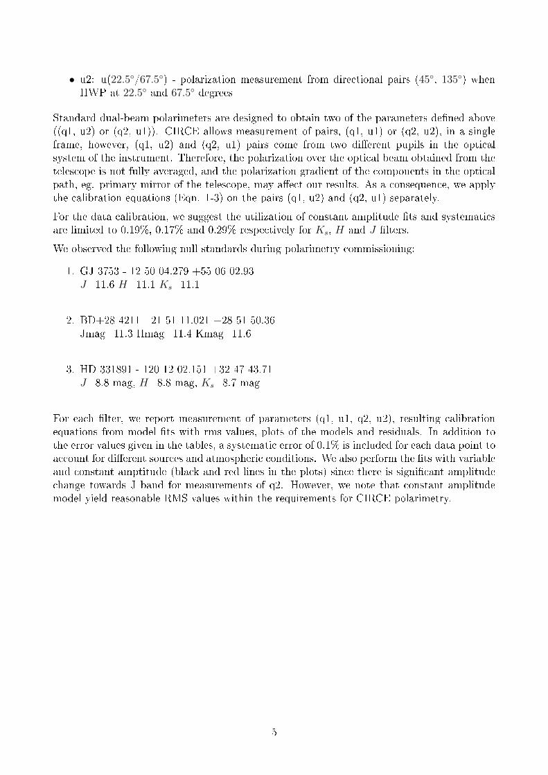
• u2: u(22.5◦/67.5◦) - polarization measurement from directional pairs (45◦, 135◦) whenHWP at 22.5◦ and 67.5◦ degrees
Standard dual-beam polarimeters are designed to obtain two of the parameters de�ned above((q1, u2) or (q2, u1)). CIRCE allows measurement of pairs, (q1, u1) or (q2, u2), in a singleframe, however, (q1, u2) and (q2, u1) pairs come from two di�erent pupils in the opticalsystem of the instrument. Therefore, the polarization over the optical beam obtained from thetelescope is not fully averaged, and the polarization gradient of the components in the opticalpath, eg. primary mirror of the telescope, may a�ect our results. As a consequence, we applythe calibration equations (Eqn. 1-3) on the pairs (q1, u2) and (q2, u1) separately.
For the data calibration, we suggest the utilization of constant amplitude �ts and systematicsare limited to 0.19%, 0.17% and 0.29% respectively for Ks, H and J �lters.
We observed the following null standards during polarimetry commissioning:
1. GJ 3753 - 12 50 04.279 +55 06 02.93J=11.6 H=11.1 Ks=11.1
2. BD+28 4211 - 21 51 11.021 +28 51 50.36Jmag=11.3 Hmag=11.4 Kmag=11.6
3. HD 331891 - 120 12 02.151 +32 47 43.71J=8.8 mag, H=8.8 mag, Ks=8.7 mag
For each �lter, we report measurement of parameters (q1, u1, q2, u2), resulting calibrationequations from model �ts with rms values, plots of the models and residuals. In addition tothe error values given in the tables, a systematic error of 0.1% is included for each data point toaccount for di�erent sources and atmospheric conditions. We also perform the �ts with variableand constant amptitude (black and red lines in the plots) since there is signi�cant amplitudechange towards J band for measurements of q2. However, we note that constant amplitudemodel yield reasonable RMS values within the requirements for CIRCE polarimetry.
5
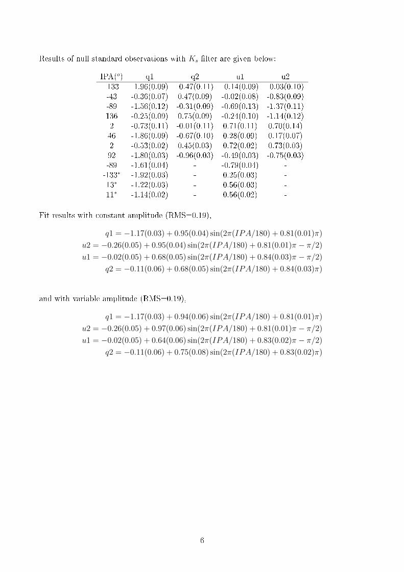
Results of null standard observations with Ks �lter are given below:
IPA(o) q1 q2 u1 u2-133 -1.96(0.09) -0.47(0.11) -0.14(0.09) -0.03(0.10)-43 -0.36(0.07) 0.47(0.09) -0.02(0.08) -0.83(0.09)-89 -1.56(0.12) -0.31(0.09) -0.69(0.13) -1.37(0.11)136 -0.25(0.09) 0.75(0.09) -0.24(0.10) -1.14(0.12)2 -0.73(0.11) -0.01(0.11) 0.71(0.11) 0.70(0.14)46 -1.86(0.09) -0.67(0.10) 0.28(0.09) 0.17(0.07)2 -0.53(0.02) 0.45(0.03) 0.72(0.02) 0.73(0.03)92 -1.80(0.03) -0.96(0.03) -0.49(0.03) -0.75(0.03)-89 -1.61(0.04) - -0.79(0.04) --133∗ -1.92(0.03) - 0.25(0.03) -13∗ -1.22(0.03) - 0.56(0.03) -11∗ -1.14(0.02) - 0.56(0.02) -
Fit results with constant amplitude (RMS=0.19),
q1 = −1.17(0.03) + 0.95(0.04) sin(2π(IPA/180) + 0.81(0.01)π)
u2 = −0.26(0.05) + 0.95(0.04) sin(2π(IPA/180) + 0.81(0.01)π − π/2)
u1 = −0.02(0.05) + 0.68(0.05) sin(2π(IPA/180) + 0.84(0.03)π − π/2)
q2 = −0.11(0.06) + 0.68(0.05) sin(2π(IPA/180) + 0.84(0.03)π)
and with variable amplitude (RMS=0.19),
q1 = −1.17(0.03) + 0.94(0.06) sin(2π(IPA/180) + 0.81(0.01)π)
u2 = −0.26(0.05) + 0.97(0.06) sin(2π(IPA/180) + 0.81(0.01)π − π/2)
u1 = −0.02(0.05) + 0.64(0.06) sin(2π(IPA/180) + 0.83(0.02)π − π/2)
q2 = −0.11(0.06) + 0.75(0.08) sin(2π(IPA/180) + 0.83(0.02)π)
6
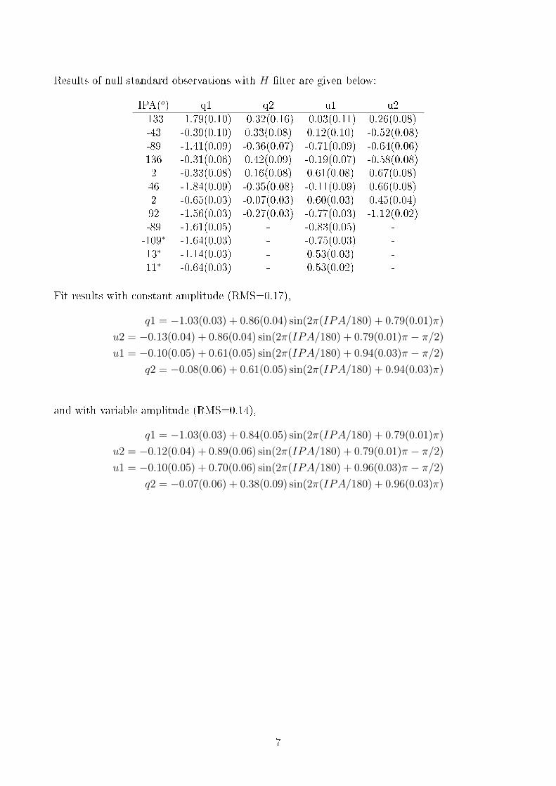
Results of null standard observations with H �lter are given below:
IPA(o) q1 q2 u1 u2-133 -1.79(0.10) -0.32(0.16) -0.03(0.11) 0.26(0.08)-43 -0.39(0.10) 0.33(0.08) 0.12(0.10) -0.52(0.08)-89 -1.41(0.09) -0.36(0.07) -0.71(0.09) -0.64(0.06)136 -0.31(0.06) 0.42(0.09) -0.19(0.07) -0.58(0.08)2 -0.33(0.08) 0.16(0.08) 0.61(0.08) 0.67(0.08)46 -1.84(0.09) -0.35(0.08) -0.11(0.09) 0.66(0.08)2 -0.65(0.03) -0.07(0.03) 0.60(0.03) 0.45(0.04)92 -1.56(0.03) -0.27(0.03) -0.77(0.03) -1.12(0.02)-89 -1.61(0.05) - -0.83(0.05) --109∗ -1.64(0.03) - -0.75(0.03) -13∗ -1.14(0.03) - 0.53(0.03) -11∗ -0.64(0.03) - 0.53(0.02) -
Fit results with constant amplitude (RMS=0.17),
q1 = −1.03(0.03) + 0.86(0.04) sin(2π(IPA/180) + 0.79(0.01)π)
u2 = −0.13(0.04) + 0.86(0.04) sin(2π(IPA/180) + 0.79(0.01)π − π/2)
u1 = −0.10(0.05) + 0.61(0.05) sin(2π(IPA/180) + 0.94(0.03)π − π/2)
q2 = −0.08(0.06) + 0.61(0.05) sin(2π(IPA/180) + 0.94(0.03)π)
and with variable amplitude (RMS=0.14),
q1 = −1.03(0.03) + 0.84(0.05) sin(2π(IPA/180) + 0.79(0.01)π)
u2 = −0.12(0.04) + 0.89(0.06) sin(2π(IPA/180) + 0.79(0.01)π − π/2)
u1 = −0.10(0.05) + 0.70(0.06) sin(2π(IPA/180) + 0.96(0.03)π − π/2)
q2 = −0.07(0.06) + 0.38(0.09) sin(2π(IPA/180) + 0.96(0.03)π)
7

Results of null standard observations with J �lter are given below:
IPA(o) q1 q2 u1 u2-133 -1.25(0.26) 0.46(0.17) -0.03(0.25) 0.21(0.27)-43 -0.41(0.11) 0.23(0.12) -0.19(0.11) -0.61(0.13)-89 -1.23(0.14) 0.03(0.13) -1.33(0.14) -0.96(0.13)136 -0.01(0.11) 0.16(0.12) -0.31(0.12) -0.61(0.10)46 -1.75(0.14) -0.23(0.13) -0.28(0.13) 0.10(0.13)2 -0.42(0.08) -0.04(0.03) 0.61(0.07) 1.01(0.05)92 -1.67(0.04) -0.07(0.04) -1.08(0.04) -0.83(0.04)-67∗ -1.15(0.04) - -0.78(0.04) -15∗ -0.97(0.04) - 0.39(0.03) -13∗ -0.84(0.03) - 0.35(0.03) -
Fit results with constant amplitude (RMS=0.29),
q1 = −1.04(0.04) + 0.97(0.06) sin(2π(IPA/180) + 0.79(0.01)π)
u2 = −0.05(0.06) + 0.97(0.06) sin(2π(IPA/180) + 0.79(0.01)π − π/2)
u1 = −0.27(0.05) + 0.56(0.06) sin(2π(IPA/180) + 0.95(0.04)π − π/2)
q2 = 0.02(0.07) + 0.56(0.06) sin(2π(IPA/180) + 0.95(0.04)π)
and with variable amplitude (RMS=0.22),
q1 = −1.04(0.04) + 0.90(0.08) sin(2π(IPA/180) + 0.79(0.01)π)
u2 = −0.04(0.06) + 1.02(0.08) sin(2π(IPA/180) + 0.79(0.01)π − π/2)
u1 = −0.28(0.05) + 0.81(0.07) sin(2π(IPA/180) + 0.99(0.03)π − π/2)
q2 = 0.04(0.07) + 0.07(0.10) sin(2π(IPA/180) + 0.99(0.03)π)
8
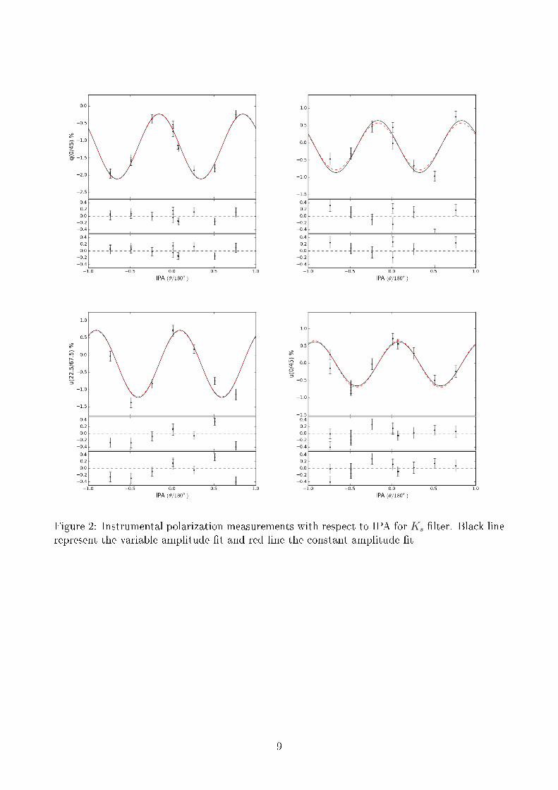
Figure 2: Instrumental polarization measurements with respect to IPA for Ks �lter. Black linerepresent the variable amplitude �t and red line the constant amplitude �t
9
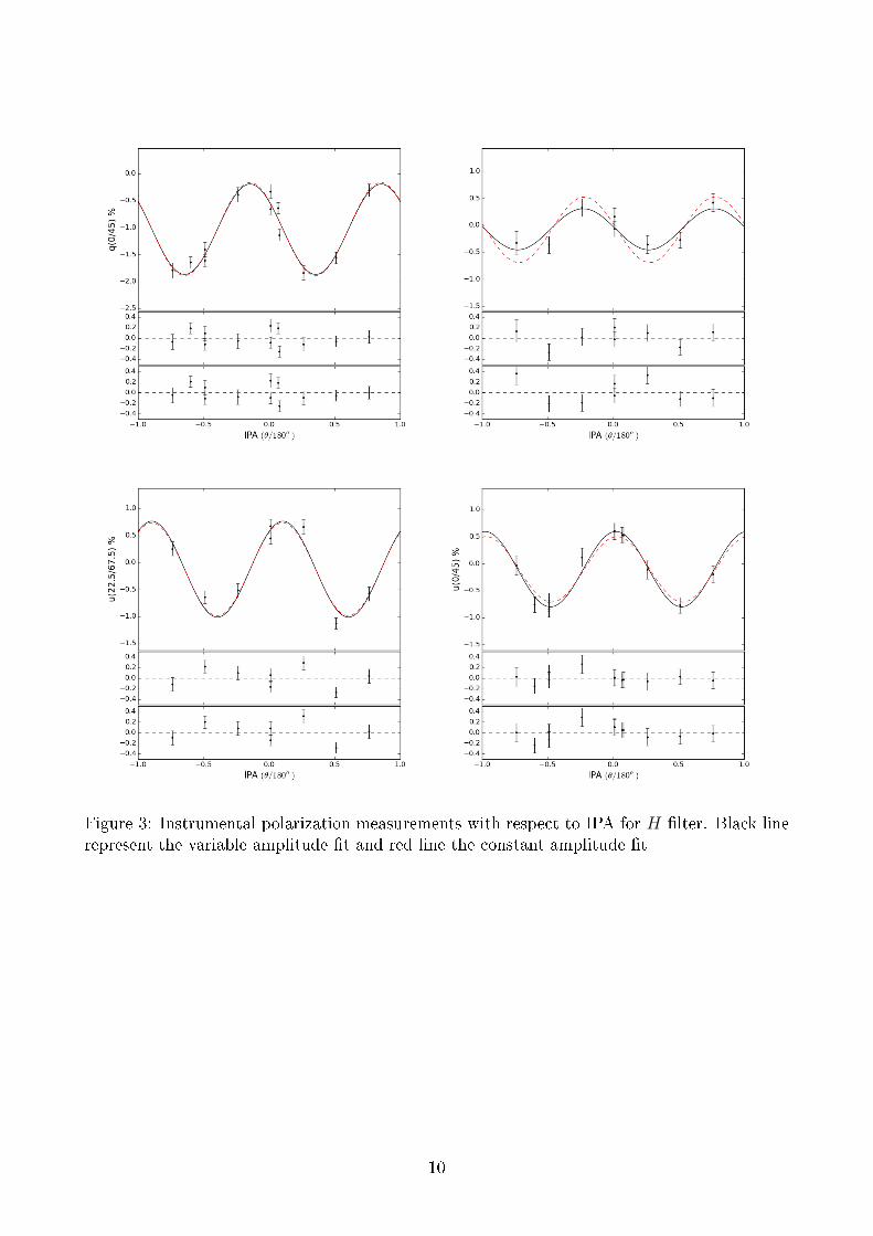
Figure 3: Instrumental polarization measurements with respect to IPA for H �lter. Black linerepresent the variable amplitude �t and red line the constant amplitude �t
10

Figure 4: Instrumental polarization measurements with respect to IPA for J �lter. Black linerepresent the variable amplitude �t and red line the constant amplitude �t
11
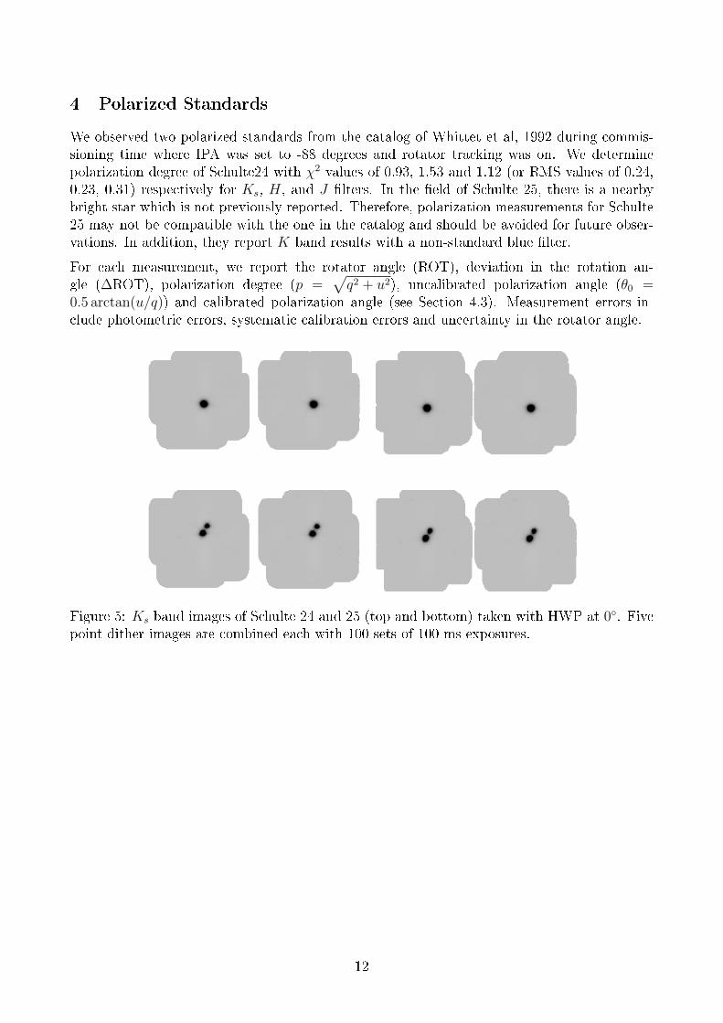
4 Polarized Standards
We observed two polarized standards from the catalog of Whittet et al, 1992 during commis-sioning time where IPA was set to -88 degrees and rotator tracking was on. We determinepolarization degree of Schulte24 with χ2 values of 0.93, 1.53 and 1.12 (or RMS values of 0.24,0.23, 0.31) respectively for Ks, H, and J �lters. In the �eld of Schulte 25, there is a nearbybright star which is not previously reported. Therefore, polarization measurements for Schulte25 may not be compatible with the one in the catalog and should be avoided for future obser-vations. In addition, they report K band results with a non-standard blue �lter.
For each measurement, we report the rotator angle (ROT), deviation in the rotation an-gle (∆ROT), polarization degree (p =
√q2 + u2), uncalibrated polarization angle (θ0 =
0.5 arctan(u/q)) and calibrated polarization angle (see Section 4.3). Measurement errors in-clude photometric errors, systematic calibration errors and uncertainty in the rotator angle.
Figure 5: Ks band images of Schulte 24 and 25 (top and bottom) taken with HWP at 0◦. Fivepoint dither images are combined each with 100 sets of 100 ms exposures.
12
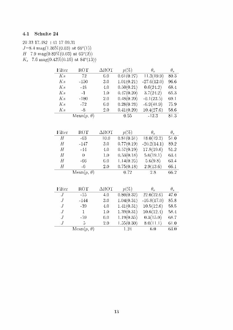
4.1 Schulte 24
20 33 17.482 +41 17 09.31J=8.4 mag(1.36%(0.03) at 66o(1))H=7.9 mag(0.89%(0.03) at 65o(2))Ks=7.6 mag(0.43%(0.16) at 84o(13))
Filter ROT ∆ROT p(%) θo θsKs -72 6.0 0.61(0.27) -11.3(19.9) 80.3Ks -150 3.0 1.01(0.21) -27.6(12.0) 96.6Ks -48 4.0 0.50(0.21) 0.6(24.2) 68.4Ks -1 1.0 0.47(0.20) 3.7(24.2) 65.3Ks -180 2.0 0.48(0.20) -0.1(23.5) 69.1Ks -72 6.0 0.28(0.28) -6.9(41.9) 75.9Ks -8 2.0 0.41(0.20) 10.4(27.6) 58.6
Mean(p, θ) 0.55 -12.3 81.3
Filter ROT ∆ROT p(%) θo θsH -63 10.0 0.81(0.31) 18.0(19.2) 51.0H -147 3.0 0.77(0.19) -20.2(14.1) 89.2H -44 4.0 0.57(0.19) 17.8(19.6) 51.2H 0 1.0 0.53(0.18) 5.6(19.1) 63.4H -66 6.0 1.14(0.25) 5.6(9.8) 63.4H -6 2.0 0.75(0.18) 2.9(13.6) 66.1
Mean(p, θ) 0.72 2.8 66.2
Filter ROT ∆ROT p(%) θo θsJ -55 4.0 0.80(0.32) 22.0(22.6) 47.0J -144 3.0 1.04(0.31) -16.8(17.0) 85.8J -39 4.0 1.41(0.31) 10.5(12.6) 58.5J 1 1.0 1.39(0.31) 10.6(12.4) 58.4J -59 6.0 1.19(0.35) 0.3(15.0) 68.7J -5 2.0 1.55(0.30) 8.0(11.1) 61.0
Mean(p, θ) 1.24 6.0 63.0
13
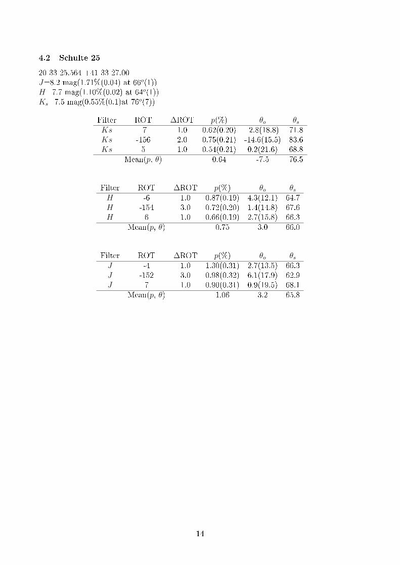
4.2 Schulte 25
20 33 25.564 +41 33 27.00J=8.2 mag(1.71%(0.04) at 66o(1))H=7.7 mag(1.10%(0.02) at 64o(1))Ks=7.5 mag(0.55%(0.1)at 76o(7))
Filter ROT ∆ROT p(%) θo θsKs -7 1.0 0.62(0.20) -2.8(18.8) 71.8Ks -156 2.0 0.75(0.21) -14.6(15.5) 83.6Ks 5 1.0 0.54(0.21) 0.2(21.6) 68.8
Mean(p, θ) 0.64 -7.5 76.5
Filter ROT ∆ROT p(%) θo θsH -6 1.0 0.87(0.19) 4.3(12.1) 64.7H -154 3.0 0.72(0.20) 1.4(14.8) 67.6H 6 1.0 0.66(0.19) 2.7(15.8) 66.3
Mean(p, θ) 0.75 3.0 66.0
Filter ROT ∆ROT p(%) θo θsJ -4 1.0 1.30(0.31) 2.7(13.5) 66.3J -152 3.0 0.98(0.32) 6.1(17.9) 62.9J 7 1.0 0.90(0.31) 0.9(19.5) 68.1
Mean(p, θ) 1.06 3.2 65.8
14
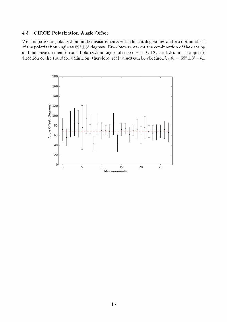
4.3 CIRCE Polarization Angle O�set
We compare our polarization angle measurements with the catalog values and we obtain o�setof the polarization angle as 69◦±3◦ degrees. Errorbars represent the combination of the catalogand our measurement errors. Polarization angles observed with CIRCE rotates in the oppositedirection of the standard de�nition, therefore, real values can be obtained by θs = 69◦±3◦−θo.
15