1 Chapter 9 Interference February 16 General considerations of interference 9.1 General...
33
1 Chapter 9 Interference February 16 General considerations of interference 9.1 General considerations Introduction: Wave equation Superposition principle Interference: The interaction between two or more waves produces in space a resultant irradiance which is different from the sum of the component irradiances: E = E 1 +E 2 , but I I 1 + I 2 . Interferometric devices: wavefront splitting and amplitude splitting. Poynting vector: is the instantaneous power flow across an unit area whose normal is parallel to S. 0 0 2 B E B E S c For a harmonic, linearly polarized plane wave: ) ( cos ) cos( ), cos( 2 0 0 0 2 0 0 ωt c ωt ωt r k B E S r k B B r k E E Irradiance ( intensity ): The time-averaged energy transport per unit area per unit time. ce. interfere light studying in 2 1 assume and , drop then We 2 1 | | 2 1 ) ( cos | | 2 0 2 0 2 0 0 0 0 0 2 2 0 0 0 2 E I c E c c ωt c S I T T T E B E r k B E
-
Upload
gabriel-quinn -
Category
Documents
-
view
221 -
download
0
Transcript of 1 Chapter 9 Interference February 16 General considerations of interference 9.1 General...

1
Chapter 9 InterferenceFebruary 16 General considerations of interference
9.1 General considerationsIntroduction: Wave equation Superposition principleInterference: The interaction between two or more waves produces in space a resultant irradiance which is different from the sum of the component irradiances:E = E1+E2, but I I1+ I2.Interferometric devices: wavefront splitting and amplitude splitting.
Poynting vector: is the instantaneous power flow across an unit
area whose normal is parallel to S.0
02
BE
BES
c
For a harmonic, linearly polarized plane wave:
)(cos)cos( ),cos( 2000
200 ωtcωtωt rkBESrkBBrkEE
Irradiance (intensity): The time-averaged energy transport per unit area per unit time.
ce.interferenlight studying in 2
1 assume and , drop thenWe
2
1||
2
1)(cos||
20
20
200000
22000
2
EIc
EccωtcSI
T
TT
E
BErkBE

2
Superposition of two planar, linearly polarized waves (vector model):
)cos()2cos(2
1
)cos()cos(
221122110201
2211020121
rkrkrkrkEE
rkrkEEEE
t
tt
cos)cos(
)cos(2
1
02012211020112
2211020121
EErkrkEE
rkrkEEEE
I
T
2211 rkrkPhase difference
1221
2122
21
2
2122
212121
2
22022
11011
2
2)()(
)cos(),(
)cos(),(
IIII
tt
tt
TTTT
EEEEE
EEEEEEEEE
rkErE
rkErE
interference term
1) When E01 and E02 are perpendicular, I12=0, no interference.2) When E01 and E02 are parallel,
cos2cos 21020112 IIEEI
cos2 2121 IIIII Note that cos averages to 0 in space: energy is conserved.

3
Total constructive interference:
Total destructive interference:
mIIIII 2 ,2 2121max
)12( ,2 2121min mIIIII
When I1=I2=I0, 2cos4)cos1(2 2
00
III
Interference fringes between two plane-waves:Bright fringes:
0constant)()()(
2)(
212121
2121
zkkykkxkk
m
zzyyxx
rkk
Fringes are parallel planes perpendicular to k1-k2 .
cos2 2121 IIIII
k1
k2
k1-k2
Exercise: Prove that the distance between the fringe planes is
Discussion: Fabrication photographic gratings.
.)2/sin(2
d

4
9.2 Conditions for interference1) For producing stable patterns, the two sources must have the same frequency.2) For producing interference patterns, the two fields must have parallel components. 3) For producing clear patterns, the two sources must have similar amplitude.4) For producing interference patterns, coherent sources are required.
Temporal coherence:Time interval tc in which the light resembles a sinusoidal wave. (~10 ns for quasi- monochromatic light sources.)Coherence length: lc= ctc.
Relation to bandwidth (uncertainty principle): tc 1.Useful relations:
Spatial coherence:The correlation of the phase of a light wave between different locations.
=Relative phase predictable
2cctcl cc

5
Read: Ch9: 1-2Homework: Ch9: 2,3 Due: February 27

r1 r2
S1 S2
m=-1 0 +1
P
m = Ma
6
At a far field, I1I2I0.
Maximum:
Minimum:
kmrr /)](2[ 2121
kmrr /)]()12[( 2121
2
)()(cos4 21212
0
rrkII
Hyperboloids
Superposition of two spherical waves:
).(//)( and strengths, sourcesimilar have waves two theSuppose
cos2
)cos()(),(
)cos()(),(
202101
2121
2220222
1110111
rErE
rErE
rErE
IIIII
tkrt
tkrt
r1 r2
P
S1 S2
Interference patterns:1) Viewing screen perpendicular to the S1-S2 axis:
Concentric Rings.2) Viewing screen parallel to the axis: Parallel
fringes (Young’s experiment).3) Maximum order of rings: -M< m <M, where M
=a/. (-a <r1-r2 <a )
February 23 Interference of spherical waves

7
Variation of the interference rings:When reducing a :1) The rings swallow. (What we observe in the Michelson interferometer.)2) The distances between neighbor rings at a fixed viewing point increases.
Superposition of a plane wave and a spherical wave:Move S1 to infinity.
r1 r2
S1 S2
m=-1 0 +1
P
m = Ma

8
(*Reading) Interference pattern and holography:1) Two coherent waves produce an interference pattern.2) The interference pattern is photographically recorded, which makes a hologram.3) Now remove one of the waves (called the object wave), and illuminate the
hologram with the other wave (called the reference wave). The removed wave is then magically reproduced in space!
)()()()()()()()()()(
:)( withdilluminateonly when wavedTransmitte
)()( :hologram theofvity Transmissi
)()()()()()()()()( :Fringes
2*222
**222
rrrrrrrrrr
r
rr
rrrrrrrrr
BABAABATAC
A
IT
BABABABAI
A B
Record
A
Reconstruction

9
(*Reading) Size of the interference rings:
.11
2 ,
211
. ,
11
2
1 )()(
., ringorder th theof radius theSuppose
2
2222221
uv
nx
x
n
uv
mMnMvu
mxvu
vuxvxurr
vuxm
nn
mmm
m
Note:1) The size of the nth ring from the center:
2) S1, S2 and the viewing screen form a lens system:
3) Distance between rings:
4) For interference between a plane wave and a spherical wave:
. nxn
.2
11 ,
111 21
n
x
uvf
fuvn
.2
,2 n
v
dn
dxnvx n
n
r1
r2
P
S1 S2
xm
uv
(xn)
.11
2
uvndn
dxn

10
(*Reading) Proof of the change of the rings (Method I, complicated but most accurate):
r1
r2
P
S1 S2
R
x
D
mmxRxDmxRDrr 222221 ),()(),(
1) Calculate dR/dx for a given m:
.)( ,When 0)(
)(
0)(
)(
0)(
21
1
2222
2222
xRxrrR
rxD
dx
dR
RxDdxdR
RxD
RDdxdR
R
RxDRDdx
d
2) Calculate dR/dm at a given R:
separation Ring ,)(
)(
)(
21
21
2222
2222
rrR
rr
dm
dR
RxDdmdR
R
RDdmdR
R
RxDRDdm
d
)],()([
),()(),(
21
21
xRrRrR
xRrRrxR
At a given R, .),(2 xRrx
The ring separation at (R, x) is given by

11
(*Reading) Proof of the change of the rings (Method II, easier):
r1
r2
P
S1 S2
R
x
D
(*Reading) Proof of the change of the rings (Method III, simplified):
mxrr cos21
1) Calculate d/dx for a given m:
)( ,When
0tan
10
)cos(
xx
xdx
d
dx
xd
2) Calculate d/dm at a given :
separation Ringsin
sincos
xdm
ddm
dxmx
The ring separation at (, x) is given by
sin),(
xx
At a given , .),( xx
The ring separation at (m, x) is given by
222),(
mxxm
At a given m, .),( xmx
R

12
Read: Ch9: 1-2No homework

a
s
13
February 25 Wavefront-splitting Interferometers
9.3 Wavefront-splitting interferometers9.3.1 Young’s experiment (1801) Young’s originality: Obtaining spatially coherent light from a pinhole, and splitting the wavefront of the spatially coherent light with two pinholes.
Optical path difference:r2 – r1 = a sin θ = ay/s ( If s>> a, s>> y )
Positions of bright fringes:
m = 0, ±1, ±2, … is the order number.
a
smy
am
m
m
ma msin
Distance between fringes:a
sy
Intensity distribution of the fringes:
s
ayI
rrkIII
2
0212
02
0 cos42
)(cos4
2cos4
ay/s

14
Effects of finite coherent length:
• Light from each slit has a coherent length lc. For sunlight (blackbody) lc3.• The waves from two slits can only interfere if r2 – r1 <lc.• The contrast of the fringes degrades when the
amount of the overlap between uncorrelated wavegroups increases.
P
r 2 – r 1
B A
A'B'
lc
Other wavefront-splitting interferometers
Fresnel’s double mirror: Slits S1 and S2 act as virtual coherent sources. They are images of slit S in the two mirrors.
= r2 – r1
PM1
M2
S1
S2
S
a
r1
r2
s
y
Shield
Space between fringes:a
sy

15
Fresnel’s double prism: Interference between light refracted from the upper and the lower prisms. The prisms produce two virtual coherent source S1 and S2.
Question: Where are S1 and S2?
S1
S2
Sa
Lloyd’s mirror: Interference between light from source S and its image S ' in the mirror.Glancing incidence causes a phase shift of , therefore the fringes are complementary to those of Young’s.
s
ayII
2
0 sin4
S
S'
as
y
16
Read: Ch9: 3Homework: Ch9: 6,14,17,19Due: March 6

17
9.4 Amplitude-splitting interferometers9.4.1 Dielectric films – double-beam interferenceApplication: Optical coating reduces or enhances the reflection of optical devices through thin-film interference effects.
Fringes of equal inclinationConsider the first two reflections (other reflections are weak if the reflectance is not large).Optical path length difference:
February 27 Amplitude-splitting Interferometers-1
dA
B
C
D
P
S
i
tnf
n1
n2
tf
t
tf
t
f
itt
f
it
f
f
dn
dndn
dndn
ACndn
ADnBCABn
cos2
cos
sin2
cos
2
sintan2cos
2
sincos
2
)(
2
1
1
1
tf dn cos2

18
coscos
coscos
coscos
coscos
ti
it
itti
tiitp
ti
ti
ttii
ttiis
nn
nn
nn
nnr
nn
nn
nn
nnr
1) External reflection, ni<nt .There is a phase shift of between the incident electric field and the reflected electric field.
2) Internal reflection, ni>nt .There is no phase shift between the incident electric field and the reflected electric field.
Phase shift in reflections when the angle of incidence is small: Eis
kii r
t
ni
Ers
kr
Ets
kt
nt
Erp
Etp
Eip

tf
tf dd
nk cos
4cos
4
19
Phase difference:Assume nf >n1, nf >n2. There is a phase shift of between external and internal reflections (when the incident angle is not large).
Bright spot: 4
)12(cos ft md
Dark spot: 4
2cos ft md
Extended source: All rays inclined at the same angle arrive at the same point.Fringes of equal inclination:Arcs centered on the perpendicular from the eye to the film.
Haidinger fringes: The fringes of equal inclination viewed at nearly normal incidence.Concentric circular bands.
t
f dn
cos2
sin
2cos
2
2

20
Read: Ch9: 4-5Homework: Ch9: 27,29,32,34Due: March 6
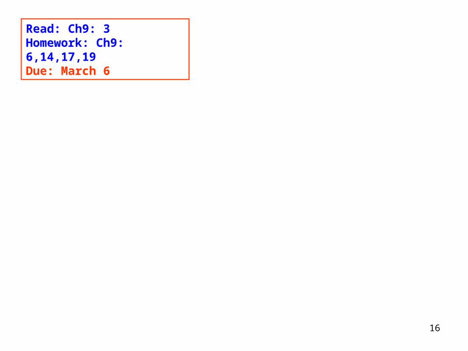
Thickness: d = xInterference maximum:
2nf dm = (m + ½)
Distance between fringes: x = f /2
.4
)12(
,4
)12(
fm
fm
mx
md
21
March 2 Amplitude-splitting Interferometers-2
Fringes of equal thicknessFizeau fringes: Contours from a non-uniform film when viewed at nearly normal incidence.
x
n1
n2
nfd
Compare: For the interference between two plane waves, the distance between
the fringe planes is .)2/sin(2
d

22
Interference colorsWhen a white light source is used in an interference experiment, each spectral component will produce its own interference pattern in space. The overlapped interference patterns from all spectral components result in the appearance of a special sequence of colors.
Calculated interference colors
Crossed polarizers
Parallel polarizers
Examples:•Soap bubbles•Oil films•Thin film coatings•Crystals between polarizers
Applications:•Identify minerals•Control coatings•Inspect strains

23
Newton’s rings: Interference pattern from an air film between two glass surfaces.
xd
Thickness:
Bright rings: 2nf dm = (m + ½)
Dark rings:
R
xddRdx
2)2(
22
.2
1
)0,1,2( ,4
)12(
Rmx
mmd
fm
fm
. Rmx fm
222 sin
2cos x
R f
Discussions:Superposition of a plane wave and a spherical wave.Fabricating zone plates.

24
Beam splitter
Movable mirror
(©WIU OptoLab)
S S1 S2
M1 M2
2dcos
P
cos2d
cos
4d
Optical path length difference:
Phase difference:
Dark fringes: md m cos2
9.4.2 Mirrored interferometersMichelson interferometer1) Compensation plate: Negates dispersion from the beam splitter2) Collimated source: Fringes of equal thickness3) Point source: Interference of spherical waves4) Extended source: Fringes of equal inclination
Application: Accurate length measurement.
from the splitter.

25
Read: Ch9: 4-5No homework
26
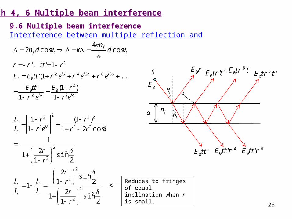
9.6 Multiple beam interferenceInterference between multiple reflection and multiple refractions:
td
S
i
nf
0E
rE0 ''0 ttrE ''30 ttrE ''50 ttrE
'0ttE2
0 ''rttE 40 ''rttE
2sin
12
1
2sin
12
1
2sin
12
1
1
cos21
)1(
1
1
1
)1(
'1
'
...)'''1('
1' ,'
cos4
cos2
22
2
22
2
22
2
24
222
2
2
2
20
20
362420
2
rr
rr
I
I
I
I
rr
rr
r
er
r
I
I
er
rE
er
ttE
erererttEE
rttrr
dn
kdn
i
t
i
r
ii
t
ii
iiit
tf
tf
March 4, 6 Multiple beam interference
Reduces to fringes of equal inclination when r is small.

27
)2/(sin1
1
1
2
2
2
2
FI
I
r
rF
i
t
it II /
/
F = 0.2 (r2 = 0.046)F = 1 (r2 = 0.17)F = 200 (r2 = 0.87)
2
21
2
r
rFCoefficient of finesse:
Airy function:)2/(sin1
)2/(sin
)2/(sin1
1
2
2
2
F
F
I
I
FI
I
i
r
i
t
)2/(sin1
1 )(
2
FA
t
f
dn
cos4

28
9.6.1 The Fabry-Perot interferometer1) High resolving power2) Prototype of laser cavity
S P
d
) large(For 21
arcsin2 2
1
)2/(sin1
1 )( 2/12
FFFF
A
Half-width of transmission:
Finesse:
F
42 2/1
2
2 FF
2
21
2
cos4
r
rF
dn t
f
)(A

29
Applications:I. How a laser wavelength is selected.1) The laser itself is a Fabry-Perot cavity. Two highly reflective mirrors select an
output of a certain wavelength with an extremely narrow bandwidth, which is called a mode.
2) The mode separation in a laser cavity (=c/2l) can be narrower than the gain profile of the laser medium, therefore output of multiple modes is possible.
3) Laser modes can be longitudinal or transverse.

30
II. How a scanning spectrum analyzer works.1) A scanning spectrum analyzer can be used to measure the modes of a laser.2) The analyzer is a Fabry-Perot interferometer whose length can be slightly varied by
piezoelectric device.3) A saw-tooth voltage is used to repeatedly change the cavity length, and the output
signal is displayed on an oscilloscope.
scanning scanning

31
i r
t
ni
nt
1
t
rr
ttr'
rt
r2
tt'
rrtrrt
rttttr
' 0'
1' 1' 22

32
Read: Ch9: 6Homework: Ch9: 37,40,42,45,47Due: March 13
Hint to P9.45:You are asked for the refractive index and the thickness of the film, so two conditions should be figured out. In order to completely eliminate the overall reflection, the light reflected from the front surface and from the rear surface of the film must have exactly the same amplitude, as well as having exactly a phase difference of . Suppose , then nf can be found from the Fresnel equations if we require the two reflections exactly cancel each other. You may also prove that won’t work for this problem.
gf nn 1
gf nn

33
“You can’t judge a book by its cover.”


![Superposition Signaling in Broadcast Interference Networks · Superposition Signaling in Broadcast Interference Networks Hoang Duong Tuan, Ho Huu Minh Tam, ... Inspired by [7], references](https://static.fdocuments.net/doc/165x107/60f2167b6f891f5d840d1ec6/superposition-signaling-in-broadcast-interference-networks-superposition-signaling.jpg)