1 Challenges for the Design of Connections and Joints in ... · PDF file1988 First bridge...
17
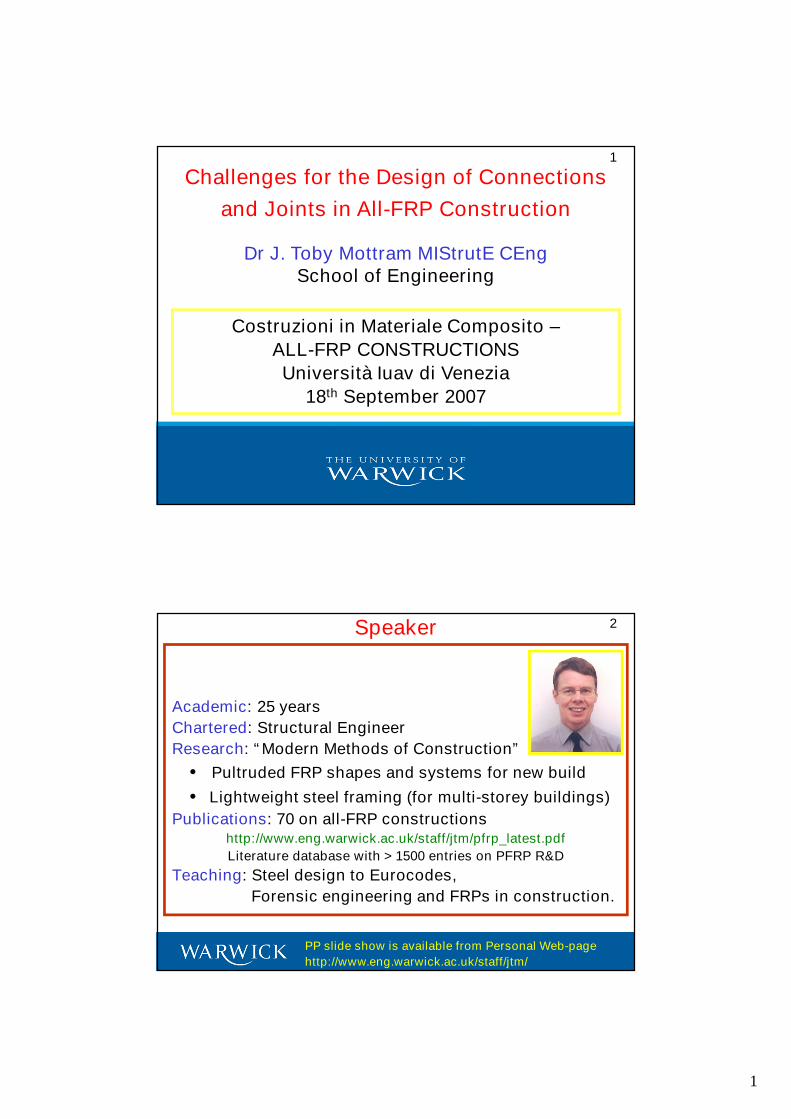
1 Dr J. Toby Mottram MIStrutE CEng School of Engineering Challenges for the Design of Connections and Joints in All-FRP Construction Costruzioni in Materiale Composito – ALL-FRP CONSTRUCTIONS Università Iuav di Venezia 18 th September 2007 1 PP slide show is available from Personal Web-page http://www.eng.warwick.ac.uk/staff/jtm/ Academic: 25 years Chartered: Structural Engineer Research:“Modern Methods of Construction” • Pultruded FRP shapes and systems for new build • Lightweight steel framing (for multi-storey buildings) Publications: 70 on all-FRP constructions http://www.eng.warwick.ac.uk/staff/jtm/pfrp_latest.pdf Literature database with > 1500 entries on PFRP R&D Teaching: Steel design to Eurocodes, Forensic engineering and FRPs in construction. Speaker 2
Transcript of 1 Challenges for the Design of Connections and Joints in ... · PDF file1988 First bridge...
1
Dr J. Toby Mottram MIStrutE CEngSchool of Engineering
Challenges for the Design of Connections
and Joints in All-FRP Construction
Costruzioni in Materiale Composito –
ALL-FRP CONSTRUCTIONS
Università Iuav di Venezia
18th September 2007
1
PP slide show is available from Personal Web-page
http://www.eng.warwick.ac.uk/staff/jtm/
Academic: 25 years
Chartered: Structural Engineer
Research: “Modern Methods of Construction”
• Pultruded FRP shapes and systems for new build
• Lightweight steel framing (for multi-storey buildings)
Publications: 70 on all-FRP constructionshttp://www.eng.warwick.ac.uk/staff/jtm/pfrp_latest.pdf
Literature database with > 1500 entries on PFRP R&D
Teaching: Steel design to Eurocodes,
Forensic engineering and FRPs in construction.
Speaker 2
2
1862 Alexander Parkes showed ‘Parkestine’ (an artificial plastic material)
1929 British Plastics Federation formed
1942 First components used in WWII aircraft
1951 First boat hull built by W. & J. Todd
1957 First Lotus Elite car
1958 Graphite fibres invented
1984 First complete airframe – Avtek 400 (USA)
and for construction applications --
1988 First bridge enclosure1 – A19 Tees Viaduct, near Middlesbrough
1992 Two-storey building1 - Severn Bridges visitors centre (slide 4)
1992 First fully bonded cable stayed bridge1 – Aberfeldy, Scotland
1994 First firewater caissons on offshore rig
1995 First road bridge1 – Bonds Mill – (private road)
1995/6 First strengthening of existing structure
1996 Very large structural frame to support electrical equipment (slide 4)
2002 First road bridge2 – West Mill – (public road) (slide 5)
2006 First “road” bridge over six-lane motorway2 (Garstang and M6)
2010(?) First house (STARTLINK®) – for sustainable homes (slide 7)
UK Historical Highlights for FRPs
1. Constructed of the Advanced Composite Construction System(ACCS), (now pultruded by Strongwell).
2. ASSET deck profile (pultruded by Fiberline Composites A/S).
3
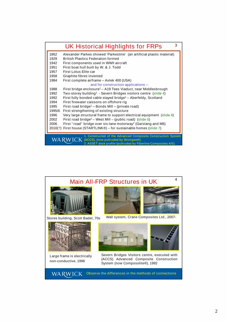
Main All-FRP Structures in UK
Stores building, Scott Bader, 70s Wall system, Crane Composites Ltd., 2007-
Large frame is electrically
non-conductive, 1996
Severn Bridges Visitors centre, executed with(ACCS) Advanced Composite ConstructionSystem (now Composolite®), 1992
4
Observe the differences in the methods of connections
3
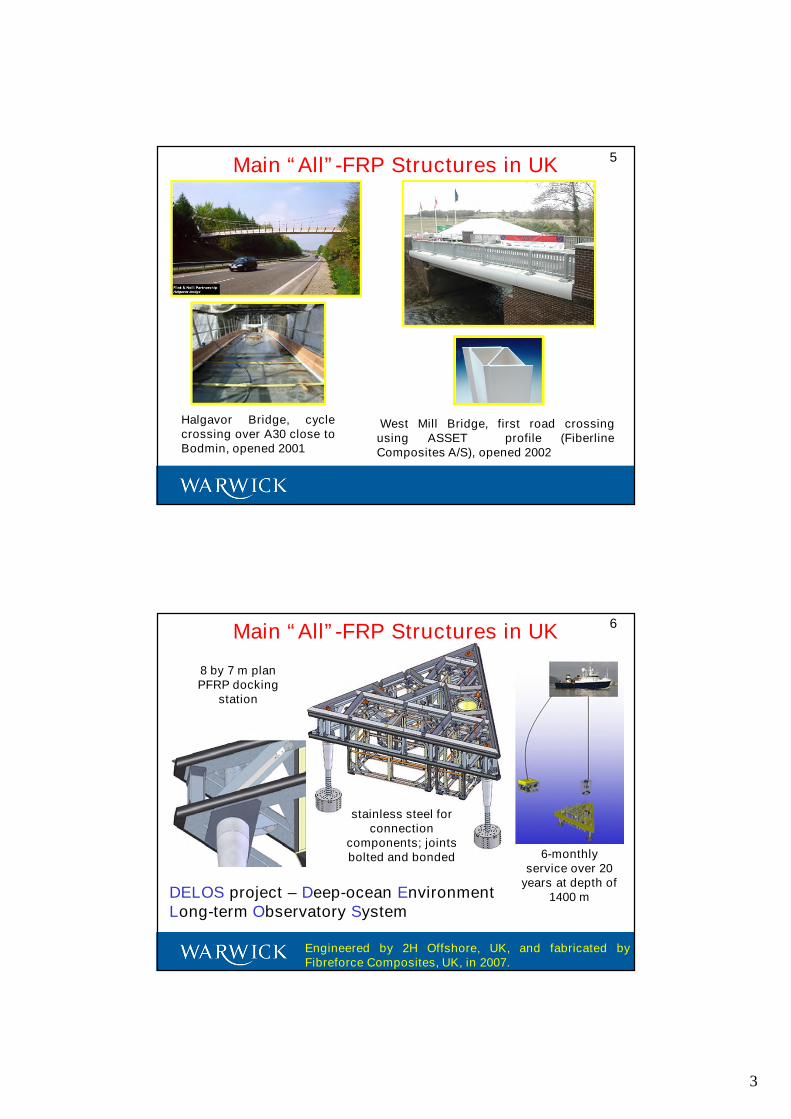
Main “All”-FRP Structures in UK
Halgavor Bridge, cyclecrossing over A30 close toBodmin, opened 2001
West Mill Bridge, first road crossingusing ASSET profile (FiberlineComposites A/S), opened 2002
5
Main “All”-FRP Structures in UK
6-monthlyservice over 20
years at depth of1400 m
8 by 7 m planPFRP docking
station
DELOS project – Deep-ocean EnvironmentLong-term Observatory System
Engineered by 2H Offshore, UK, and fabricated byFibreforce Composites, UK, in 2007.
6
stainless steel forconnection
components; jointsbolted and bonded
4
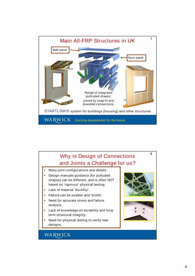
Main All-FRP Structures in UK
STARTLINK® system for buildings (housing) and other structures
Range of integratedpultruded shapes;
joined by snap-fit anddowelled connections.
Exciting development for the future.
Wall panel
floor panel
7
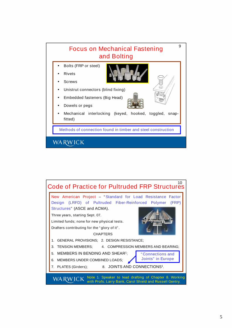
8Why is Design of Connections
and Joints a Challenge for us?• Many joint configurations and details.
• Design manuals guidance (for pultuded
shapes) can be different, and is often NOT
based on ‘rigorous’ physical testing.
• Lack of material ‘ductility’.
• Failure can be sudden and ‘brittle’.
• Need for accurate stress and failure
analysis.
• Lack of knowledge on durability and long-
term structural integrity.
• Need for physical testing to verify new
designs.
5
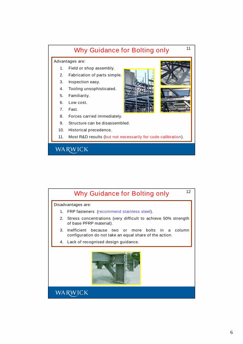
9Focus on Mechanical Fastening
and Bolting
• Bolts (FRP or steel)
• Rivets
• Screws
• Unistrut connectors (blind fixing)
• Embedded fasteners (Big Head)
• Dowels or pegs
• Mechanical interlocking (keyed, hooked, toggled, snap-
fitted)
Methods of connection found in timber and steel construction
10Code of Practice for Pultruded FRP Structures
New American Project – “Standard for Load Resistance Factor
Design (LRFD) of Pultruded Fiber-Reinforced Polymer (FRP)
Structures” (ASCE and ACMA).
Three years, starting Sept. 07.
Limited funds; none for new physical tests.
Drafters contributing for the “glory of it”.
CHAPTERS
1. GENERAL PROVISIONS; 2. DESIGN RESISTANCE;
3. TENSION MEMBERS; 4. COMPRESSION MEMBERS AND BEARING;
5. MEMBERS IN BENDING AND SHEAR1;
6. MEMBERS UNDER COMBINED LOADS;
7. PLATES (Girders); 8. JOINTS AND CONNECTIONS1.
Note 1. Speaker to lead drafting of Chapter 8. Workingwith Profs. Larry Bank, Carol Shield and Russell Gentry.
“Connections andJoints” in Europe
6
Advantages are:
1. Field or shop assembly.
2. Fabrication of parts simple.
3. Inspection easy.
4. Tooling unsophisticated.
5. Familiarity.
6. Low cost.
7. Fast.
8. Forces carried immediately.
9. Structure can be disassembled.
10. Historical precedence.
11. Most R&D results (but not necessarily for code calibration).
11Why Guidance for Bolting only
12Why Guidance for Bolting only
Disadvantages are:
1. FRP fasteners (recommend stainless steel).
2. Stress concentrations (very difficult to achieve 50% strengthof base PFRP material).
3. Inefficient because two or more bolts in a columnconfiguration do not take an equal share of the action.
4. Lack of recognised design guidance.
7
13General Philosophy to the Approach
Drafting will be to combine aspects of the concepts from:
1. ASCE 16 standard for wood.
2. AISC specification for bolted connections in steel trusses orsimple steel frames (braced with no sway)
3. AISC specification for connections in cold formed steelmembers.
4. RCSC Specification for Structural Joints Using ASTM A325 orA490 Bolts.
5. code and background chapters “Connection Design” in theEUROCOMP Design Code and Handbook.
6. design guidance on connections in the pultruders’ DesignManuals.
Structural Eurocodes do provide equivalent conceptsfound in 1 to 3 above.
14
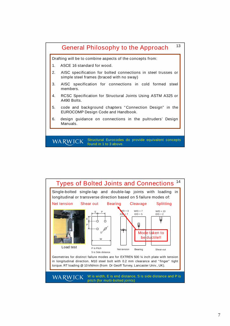
Single-bolted single-lap and double-lap joints with loading in
longitudinal or transverse direction based on 5 failure modes of:
Net tension Shear out Bearing Cleavage Splitting
Geometries for distinct failure modes are for EXTREN 500 ¼ inch plate with tension
in longitudinal direction. M10 steel bolt with 0.2 mm clearance and “finger” tight
torque. RT loading @ 10 kN/min (from Dr Geoff Turvey, Lancaster Univ., UK).
Types of Bolted Joints and Connections
S P
E
P
D
W
E/D = 7
W/D = 3
Net-tension Shear-out
W/D = 7
E/D = 5W/D = 10E/D = 2
P is Pitch
S is Side distance
W is width, E is end distance, S is side distance and P ispitch (for multi-bolted joints)
Mode taken tobe ductile!!
Load test
8
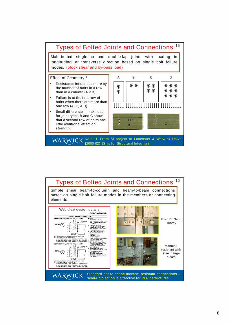
15
Multi-bolted single-lap and double-lap joints with loading in
longitudinal or transverse direction based on single bolt failure
modes. (block shear and by-pass load)
Types of Bolted Joints and Connections
Effect of Geometry:1
• Resistance influenced more bythe number of bolts in a rowthan in a column (A < B).
• Failure is at the first row ofbolts when there are more thanone row (A, C, & D).
• Small difference in max. loadfor joint types B and C showthat a second row of bolts haslittle additional effect onstrength.
A B C D
B C
Note: 1. From SI project at Lancaster & Warwick Univs.
(2000-02) (SI is for Structural Integrity)
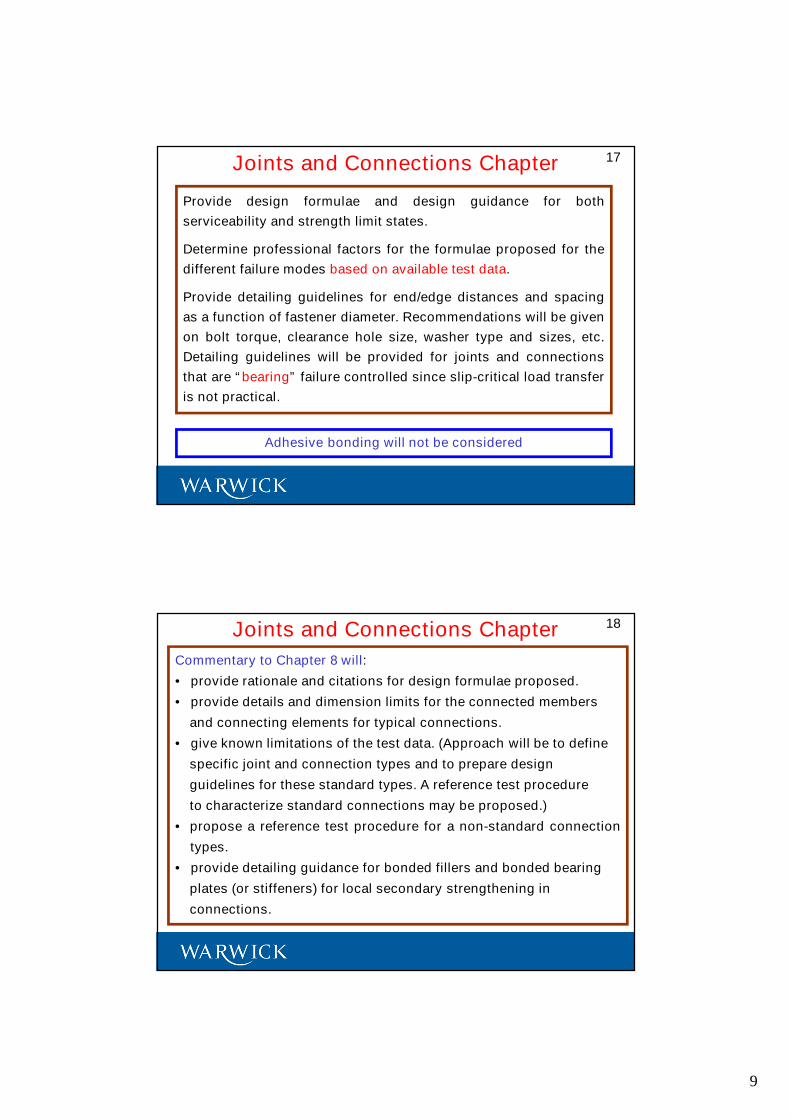
16
Simple shear beam-to-column and beam-to-beam connectionsbased on single bolt failure modes in the members or connectingelements.
Types of Bolted Joints and Connections
Web cleat design details
From Dr GeoffTurvey
Standard not to scope moment resistant connections –semi-rigid action is attractive for PFRP structures.
Moment-resistant withsteel flange
cleats
9
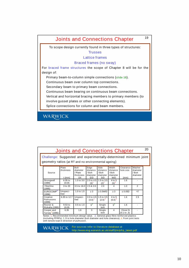
17
Provide design formulae and design guidance for both
serviceability and strength limit states.
Determine professional factors for the formulae proposed for the
different failure modes based on available test data.
Provide detailing guidelines for end/edge distances and spacing
as a function of fastener diameter. Recommendations will be given
on bolt torque, clearance hole size, washer type and sizes, etc.
Detailing guidelines will be provided for joints and connections
that are “bearing” failure controlled since slip-critical load transfer
is not practical.
Joints and Connections Chapter
Adhesive bonding will not be considered
18
Commentary to Chapter 8 will:
• provide rationale and citations for design formulae proposed.
• provide details and dimension limits for the connected members
and connecting elements for typical connections.
• give known limitations of the test data. (Approach will be to define
specific joint and connection types and to prepare design
guidelines for these standard types. A reference test procedure
to characterize standard connections may be proposed.)
• propose a reference test procedure for a non-standard connection
types.
• provide detailing guidance for bonded fillers and bonded bearing
plates (or stiffeners) for local secondary strengthening in
connections.
Joints and Connections Chapter
10
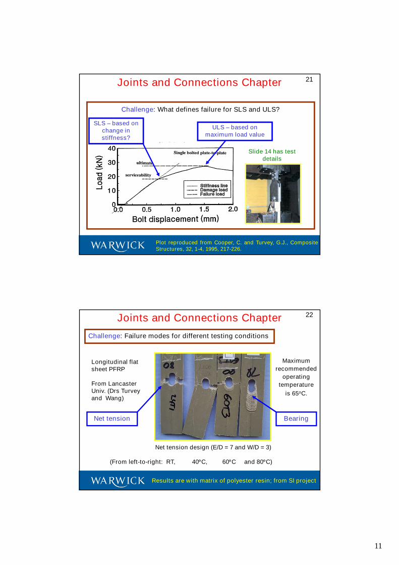
19Joints and Connections Chapter
To scope design currently found in three types of structures:
Trusses
Lattice frames
Braced frames (no sway)
For braced frame structures the scope of Chapter 8 will be for the
design of:
Primary beam-to-column simple connections (slide 16).
Continuous beam over column top connections.
Secondary beam to primary beam connections.
Continuous beam bearing on continuous beam connections.
Vertical and horizontal bracing members to primary members (to
involve gusset plates or other connecting elements).
Splice connections for column and beam members.
20Joints and Connections ChapterChallenge: Suggested and experimentally-determined minimum joint
geometry ratios (at RT and no environmental ageing)
Source
Platethickness
t (mm)
Boltdiameter/ Platethickness
D/t
Edgedistance/ Boltdiameter
E/D
Sidedistance/ Boltdiameter
S/D
Widthdistance/ Boltdiameter
W/D
Clearancehole size
(mm)
Washerdiameter/ Boltdiameter
Strongwell(1989)
6.35 to19.05
1.0 to 3.0 2.0 to 4.5
(3)1
1.5 to 3.5
(2)1
4 to 5
(5)1
1.6 -
Fiberline(1995)
3 to 20 0.5 to 16.0 2.5 & 3.5 2.0 4 1.0 2
EUROCOMP2
(1996)
Unspeci-fied
1.0 to 1.5 ≥ 3 ≥ 0.5W/D ≥ 3 ≤ 0.05D >2
CreativePultrusions(1999)
6.35 to 12.7 Unspeci-fied
2.0 to 4.5
(3.0)1
1.5 to 3.5
(2.0)1
4 to 5
(5.0)1
1.6 2.5
Rosner &Rizkalla (1995)
9.53 to19.05
0.5 to 1.0 53 Single-
bolt5
3 1.6 -
Cooper and
Turvey4
(1995)
6.35 1.6 3 Single-bolt
4 Close fit(0.1 to .3)
-
Notes: 1. Recommended minimum design value. 2. General glass fibre reinforced plastics(including PFRPs). 3. D is hole diameter (bolt diameter and hole clearance). 4. From joint testswith tensile load in direction of pultrusion.
For sources refer to literature database at
http://www.eng.warwick.ac.uk/staff/jtm/pfrp_latest.pdf
11
21Joints and Connections Chapter
Challenge: What defines failure for SLS and ULS?
Slide 14 has testdetails
SLS – based onchange instiffness?
ULS – based onmaximum load value
Plot reproduced from Cooper, C. and Turvey, G.J., CompositeStructures, 32, 1-4, 1995, 217-226.
22Joints and Connections Chapter
Challenge: Failure modes for different testing conditions
Longitudinal flatsheet PFRP
From LancasterUniv. (Drs Turveyand Wang)
Net tension design (E/D = 7 and W/D = 3)
(From left-to-right: RT, 40°C, 60°C and 80°C)
Net tension Bearing
Results are with matrix of polyester resin; from SI project
Maximum
recommended
operating
temperature
is 65oC.
12
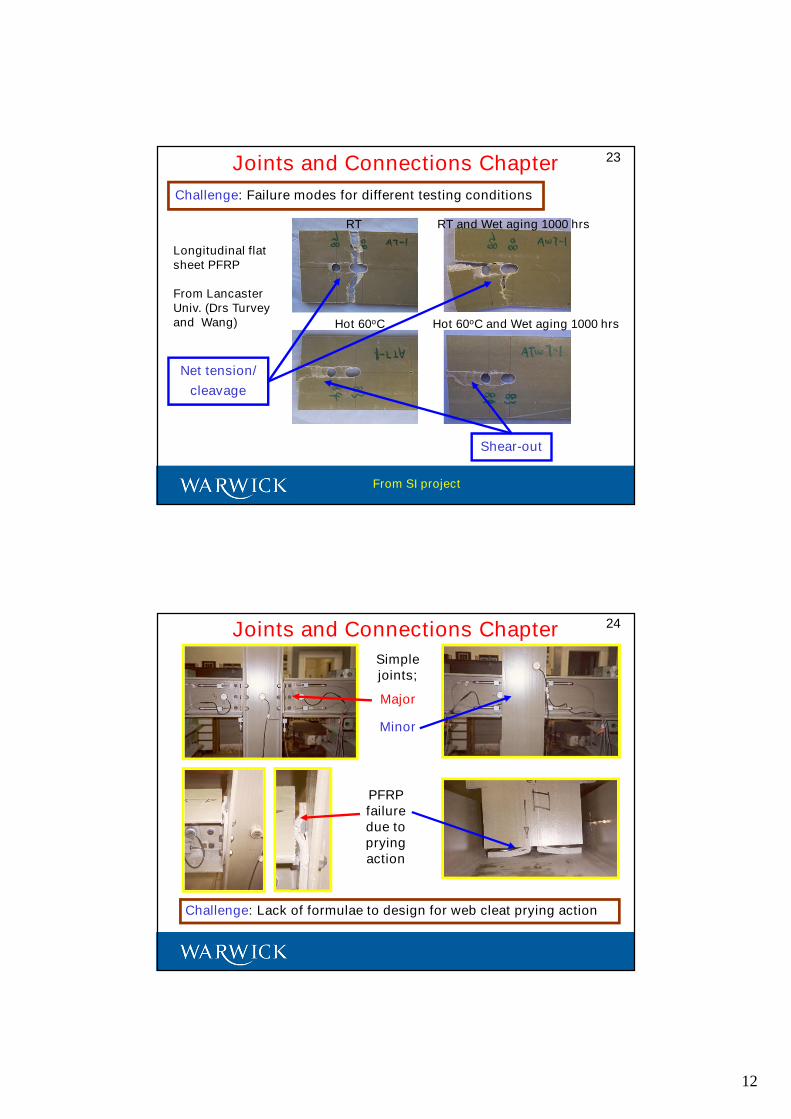
23Joints and Connections Chapter
Challenge: Failure modes for different testing conditions
Longitudinal flatsheet PFRP
From LancasterUniv. (Drs Turveyand Wang)
RT RT and Wet aging 1000 hrs
Hot 60oC Hot 60oC and Wet aging 1000 hrs
From SI project
Net tension/
cleavage
Shear-out
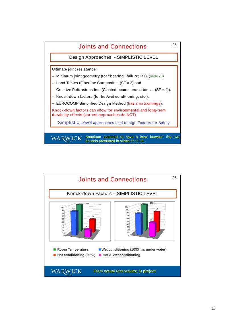
24Joints and Connections Chapter
Challenge: Lack of formulae to design for web cleat prying action
Simplejoints;
Major
Minor
PFRPfailuredue topryingaction
13
25Joints and Connections
Ultimate joint resistance:
– Minimum joint geometry (for “bearing” failure; RT). (slide 20)
– Load Tables (Fiberline Composites (SF = 3) and
Creative Pultrusions Inc. (Cleated beam connections – (SF = 4)).
– Knock-down factors (for hot/wet conditioning, etc.).
– EUROCOMP Simplified Design Method (has shortcomings).
Knock-down factors can allow for environmental and long-termdurability effects (current approaches do NOT)
Simplistic Level approaches lead to high Factors for Safety
Design Approaches - SIMPLISTIC LEVEL
American standard to have a level between the twobounds presented in slides 25 to 29.
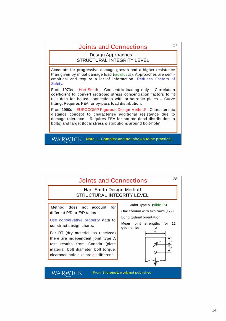
26Joints and Connections
Knock-down Factors – SIMPLISTIC LEVEL
100
48
85
25
0
10
20
30
40
50
60
70
80
90
100
100
7675
48
0
10
20
30
40
50
60
70
80
90
100
Room Temperature Wet conditioning (1000 hrs under water)
Hot conditioning (60oC) Hot & Wet conditioning
From actual test results; SI project
14
27Joints and ConnectionsDesign Approaches -
STRUCTURAL INTEGRITY LEVEL
Accounts for progressive damage growth and a higher resistancethan given by initial damage load (see slide 21). Approaches are semi-empirical and require a lot of information! Reduces Factors ofSafety.
From 1970s – Hart-Smith – Concentric loading only – Correlationcoefficient to convert isotropic stress concentration factors to fittest data for bolted connections with orthotropic plates – Curvefitting. Requires FEA for by-pass load distribution.
From 1990s – EUROCOMP Rigorous Design Method1 - Characteristicdistance concept to characterise additional resistance due todamage tolerance – Requires FEA for source (load distribution tobolts) and target (local stress distributions around bolt-hole).
Note: 1. Complex and not shown to be practical.
28Joints and Connections
Hart-Smith Design MethodSTRUCTURAL INTEGRITY LEVEL
Method does not account for
different P/D or E/D ratios
Use conservative property data to
construct design charts.
For RT (dry material, as received)
there are independent joint type A
test results from Canada (plate
material, bolt diameter, bolt torque,
clearance hole size are all different.
W
E
P
D
Joint Type A (slide 15)
One column with two rows (1x2)
Longitudinal orientation
Mean joint strengths for 12geometries
From SI project; work not published.
15
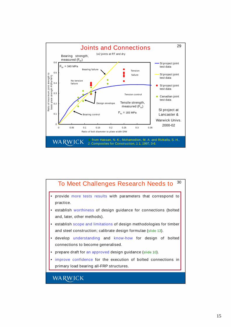
1x2 joints at RT and dry
0
0.1
0.2
0.3
0.4
0.5
0.6
0 0.05 0.1 0.15 0.2 0.25 0.3 0.35
Ratio of bolt diameter to plate width D/W
Ra
tio
of
ma
xim
um
join
tst
ren
gth
to
ba
sic
pla
test
ren
gth
P/(
Ftu
*W*t
)
SI project jointtest data
SI project jointtest data
SI project jointtest data
Canadian jointtest data
Fbr = 340 MPa
No tensionfailure
Bearing failureTension
failure
Design envelope
Bearing control
Tension control
Ftu = 183 MPa
29Joints and Connections
from Hassan, N. K., Mohamedien, M. A. and Rizkalla, S. H.,J. Composites for Construction, 1 1, 1997, 3-6.
SI project at
Lancaster &
Warwick Univs.
2000-02
Bearing strength,measured (Fbr)
Tensile strength,measured (Ftu)
• provide more tests results with parameters that correspond to
practice.
• establish worthiness of design guidance for connections (bolted
and, later, other methods).
• establish scope and limitations of design methodologies for timber
and steel construction; calibrate design formulae (slide 13).
• develop understanding and know-how for design of bolted
connections to become generalised.
• prepare draft for an approved design guidance (slide 10).
• improve confidence for the execution of bolted connections in
primary load bearing all-FRP structures.
To Meet Challenges Research Needs to 30
16
• UK has seen a steady progress in the execution of novel and
innovative structures of FRP structural materials, and this
progress can be expected to grow as technologies mature and
we seek sustainable solutions for buildings and bridges.
• Knowing how to design safe and reliable connections and joints
remains the biggest challenge for those wanting to exploit FRPs
in construction.
• For pultruded shapes bolting is the primary connection method
(it provides flexibility and is familiar).
• There is a need for standard connection details giving easy to
assemble structures that are safe, reliable and cost-effective.
Concluding Remarks 31
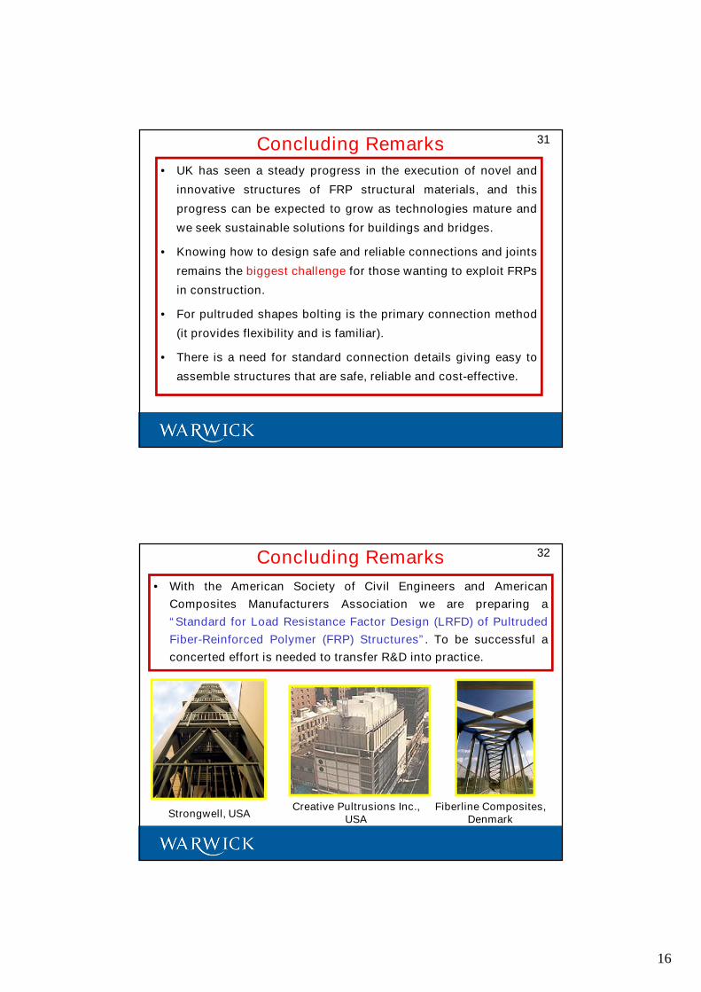
• With the American Society of Civil Engineers and American
Composites Manufacturers Association we are preparing a
“Standard for Load Resistance Factor Design (LRFD) of Pultruded
Fiber-Reinforced Polymer (FRP) Structures”. To be successful a
concerted effort is needed to transfer R&D into practice.
Concluding Remarks 32
Strongwell, USAFiberline Composites,
DenmarkCreative Pultrusions Inc.,
USA
17
This image cannot currently be displayed.
Email: [email protected] 2007
Thank you for your attention.
Any questions?
33