1 Catalog of useful (structural) modules and architectures In this course we will be working mostly...
42
1 Catalog of useful (structural) modules and architectures In this course we will be working mostly at the BEHAVIORAL and STRUCTURAL levels. We will rely on the Altera design tools to do MOST of the physical design and optimization. Here we will quickly review the basic STRUCTURAL building blocks commonly used--complete sets, muxes, demuxes, adders, flip-flops, counters, registers, memory, I/O. We will also briefly review the
-
Upload
giles-lambert -
Category
Documents
-
view
214 -
download
1
Transcript of 1 Catalog of useful (structural) modules and architectures In this course we will be working mostly...

1
Catalog of useful (structural) modules and architectures
In this course we will be working mostly at theBEHAVIORAL and STRUCTURAL levels.
We will rely on the Altera design tools to do MOST of the physical design and optimization.
Here we will quickly review the basic STRUCTURAL building blocks commonly used--complete sets, muxes, demuxes, adders, flip-flops, counters, registers, memory, I/O.
We will also briefly review the structure of typical basic computer architectures.

2
"Useful" modules. I. Combinational modules
a. choice functions: enable multiplexor demultiplexor b. arithmetic functions: addition (half adder, full adder,incrementer) negation, subtraction multiplier divider comparators c. other combinational functions: digit conversion error correction
II. Sequential modules a. flip-flops (D, J-K, T); registers; shift registers b. counters c. control units d. pipelined units III. RAM and ROM IV. I/O
3
a. choice functions:
A simple enable allows a signal to pass from a pointx in a circuit to a point y:
x y
enable
4
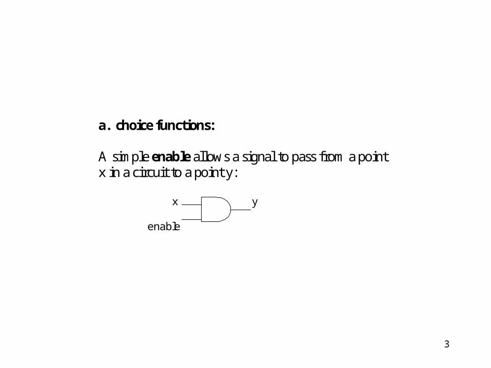
An n-input multiplexor (mux) has n inputs and one output,chosen from among the n inputs by log2n control lines.
S S A
OUTB
A OUT
B
2-input multiplexor: if S = 1, select A; if S = 0, select B
2-mux

5
S1
A S2B
OUT
C
D
4-input multiplexor built as a tree of 2-inputmultiplexors
2-MUX
2-MUX
2-MUX

6
A demultiplexor transfers one input to exactlyone of n possible outputs, based on log2 n controllines: S
A OUT1
A S OUT1 OUT2
OUT2
2-input demultiplexor
Note: if we omit A, then the value of S chooseswhich output is 1; this circuit is called a "decoder".
Question: how do you design an n-outputdemultiplexor?
2-DEMUX

7
b. (integer) arithmetic modules:The design of circuits to perform arithmetic has beenstudied extensively, and much research is still beingdone in this area. Since many of the tasks which atypical processor has to do involve arithmeticcomputations, improving the efficiency of arithmeticcircuits can have a great impact on the efficiency ofthe whole processor design. Here we present only afew basic arithmetic circuits.
8
Addition: example: if we add the three-bit binarynumbers A = 101 and B = 111, we get 1100. In eachbit position i we have three inputs, Ai, Bi, and "carry-in" Ci (with C0, the carry-in to the least significantbit, = 0). At each bit we compute two outputs, thesum Si and the "carry-out" Ci+1. To see how toimplement the bit-wise calculations we make a truthtable:

9
Ai Bi Ci Si Ci+1
0 0 0 0 00 0 1 1 00 1 0 1 01 0 0 1 00 1 1 0 11 0 1 0 11 1 0 0 11 1 1 1 1
Note that we have listed the inputs in groups,according to the number of 1's. Here we are usingthe fact that integer addition is associative andcommutative, so input 101 and input 011 will givethe same output, for example.
We see that in the sum column the pattern is that anodd number of 1's gives 1 and and even number gives0. This is easily implemented by the xor function.
10
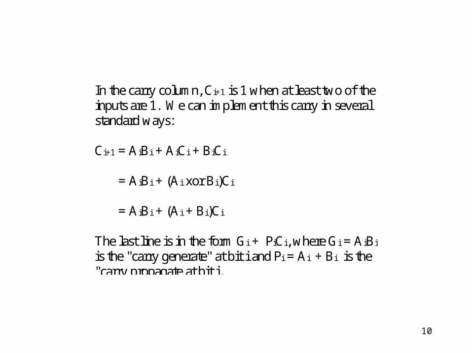
In the carry column, Ci+1 is 1 when at least two of theinputs are 1. We can implement this carry in severalstandard ways:
Ci+1 = AiBi + AiCi + BiCi
= AiBi + (Ai xor Bi)Ci
= AiBi + (Ai + Bi)Ci
The last line is in the form Gi + PiCi, where Gi = AiBi
is the "carry generate" at bit i and Pi = Ai + Bi is the"carry propagate at bit i.
11
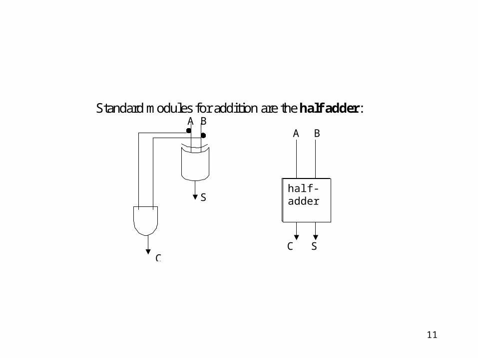
Standard modules for addition are the half adder: A B A B
S
C S C
half-
adder
half-adder
12
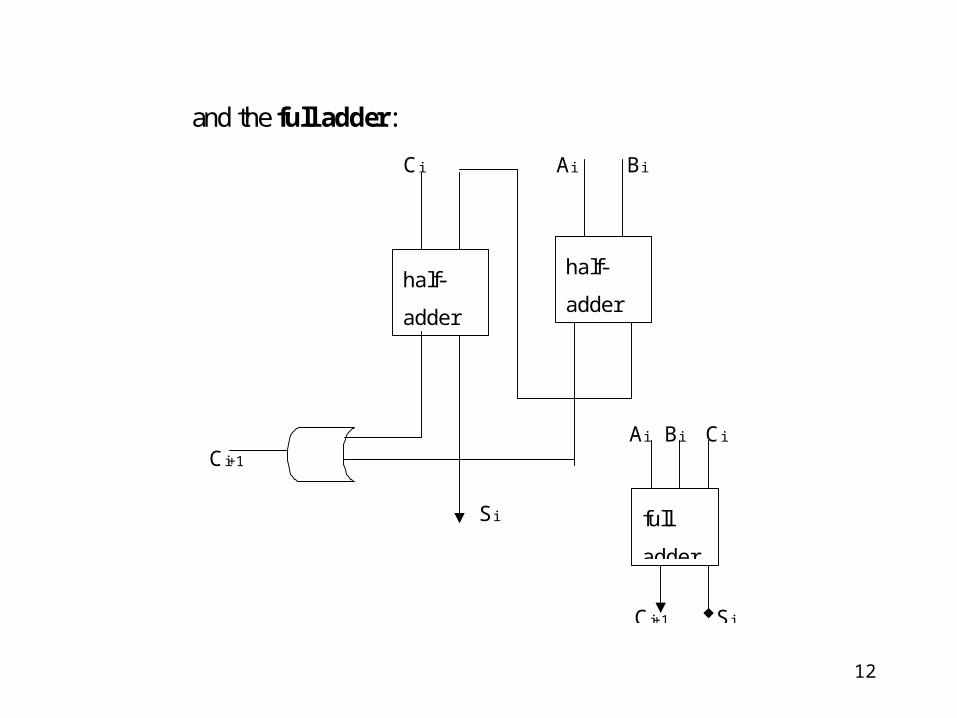
and the full adder:
Ci Ai Bi
Ai Bi Ci
Ci+1
Si
Ci+1 Si
half-
adderhalf-
adder
full
adder
13
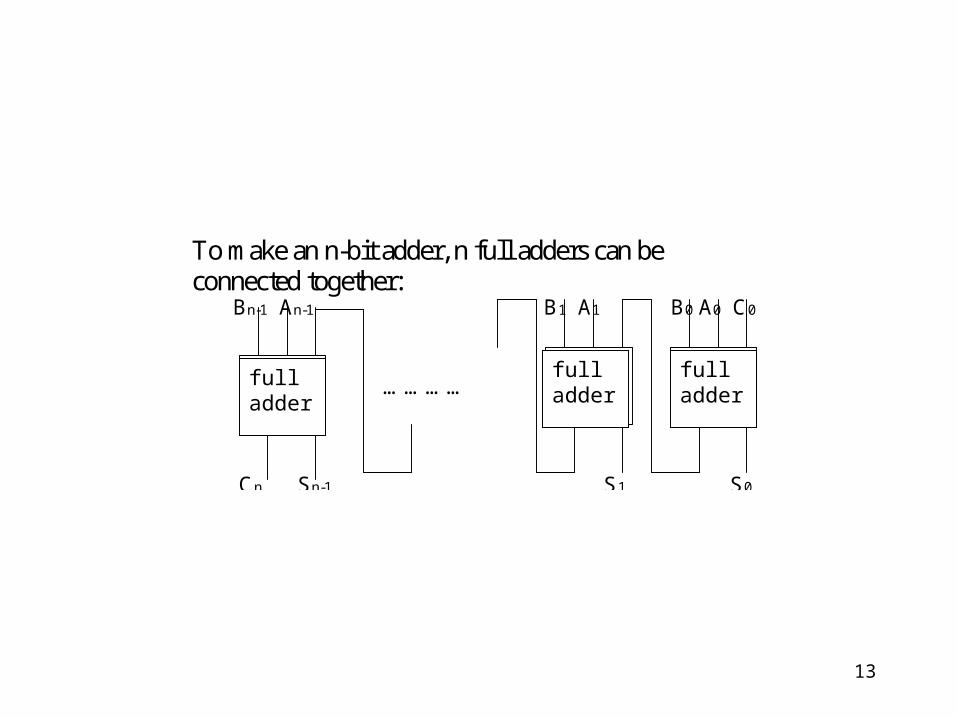
To make an n-bit adder, n full adders can beconnected together: Bn-1 An-1 B1 A1 B0 A0 C0
…………
Cn Sn-1 S1 S0
full
adder
full
adder
full
adder
fulladder
fulladder
fulladder
14
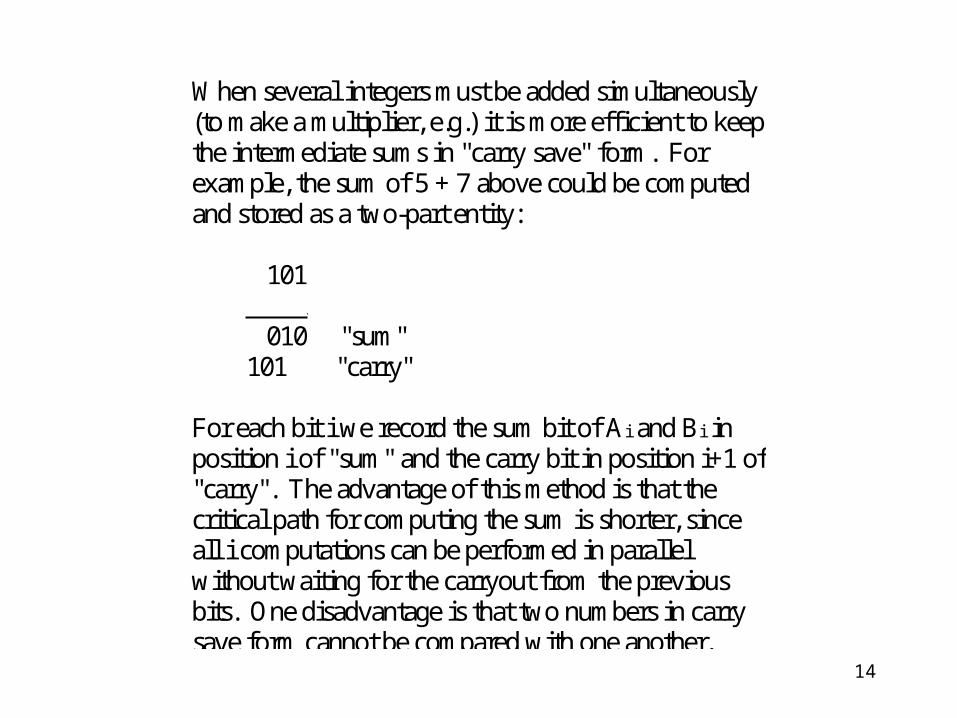
When several integers must be added simultaneously(to make a multiplier, e.g.) it is more efficient to keepthe intermediate sums in "carry save" form. Forexample, the sum of 5 + 7 above could be computedand stored as a two-part entity:
101 + 111 010 "sum" 101 "carry"
For each bit i we record the sum bit of Ai and Bi inposition i of "sum" and the carry bit in position i+1 of"carry". The advantage of this method is that thecritical path for computing the sum is shorter, sinceall i computations can be performed in parallelwithout waiting for the carryout from the previousbits. One disadvantage is that two numbers in carrysave form cannot be compared with one another.

15
Negation: the two most "popular" systems forrepresenting negative integers in a digital computerare called "2's complement" and "1's complement".We will not discuss these here. you should befamiliar with at least one of these systems fromearlier courses. Negative integers may also berepresented in sign-magnitude form, but this makessubtraction and comparison more difficult toimplement.
16
Subtraction: if integers are represented in 1'scomplement form, the additive inverse of an integeris just its bitwise complement. Thus a subtractor canbe built by complementing each bit of the subtrahendand adding the result to the minuend. If 2'scomplement form is used instead, a 1 must be addedto the subtrahend after the complementation step andbefore the addition step.
17
An incrementer is a special purpose adder whichjust adds 1 to its imput. A decrementer justsubtracts 1. Because of their specialized functions,incrementers and decrementers can be designed muchmore simply than general purpose adders andsubtractors.

18
Multiplication: clearly a 1-bit multiplier is just anAND gate. We can build a simple multiplier for n-bitintegers from and gates, shifters, and adders. Asmentioned above, the n-1 additions can be speededup by using carry-save form. To obtain the finalresult, one true addition must be done at the last step.
Division: integer division, giving quotient andremainder, can be accomplished by repeatedsubtractions.
19
Comparators: several different types ofcomparators may be useful. A magnitudecomparator compares the magnitude of two(positive) integers. An arithmetic comparatorcompares two signed integers. A subtractor may beused as an arithmetic comparator. The majorityfunction of n inputs is 1 if more than half the inputsare 1, otherwise it is 0. Each input essentially "votes"for the majority (the carry-out of a full adder is amajority of the 3 inputs). The parity of n bits is 1 ifan odd number of the bits are 1, otherwise it is 0 (thesum bit in a full adder is the parity of the 3 inputs).The parity of n bits may be computed by xoring allthe bits together.
20
Digit conversion: it is often necessary to convertintegers from BCD (binary coded decimal) to binaryformat or vice versa. Modules to do this conversioncan be constructed. We leave the construction as anexercise.
21
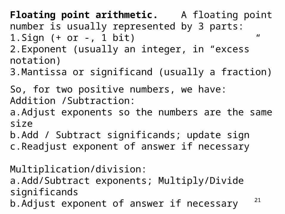
Floating point arithmetic. A floating point number is usually represented by 3 parts:1.Sign (+ or -, 1 bit)2.Exponent (usually an integer, in “excess” notation)3.Mantissa or significand (usually a fraction)
So, for two positive numbers, we have:Addition /Subtraction: a.Adjust exponents so the numbers are the same sizeb.Add / Subtract significands; update signc.Readjust exponent of answer if necessary
Multiplication/division:a.Add/Subtract exponents; Multiply/Divide significandsb.Adjust exponent of answer if necessary
Basic operations can be done with integer modules, shifting. Special cases (e.g., overflow, underflow) cannot be ignored.
22
Error detection/correction: when data istransmitted from one place to another, it is possiblefor some of the bits to be altered during thetransmission process. Thus it is common for extrabits to be transmitted with the data to enable thereceiver to detect and/or correct any transmissionerrors. One simple example of this is the addition ofa parity bit to an n-bit message. The sender can thenset this extra bit so that the parity of the n+1 bits isknown and can be checked by the receiver. If theparity has not been preserved, at least one error hasoccurred. A unit for setting/checking parity can bebuilt from xor gates.
23
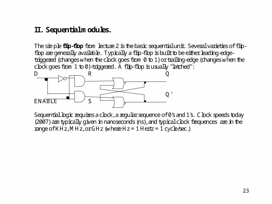
II. Sequential modules. The simple flip-flop from lecture 2 is the basic sequential unit. Several varieties of flip-flop are generally available. Typically a flip-flop is built to be either leading-edge-triggered (changes when the clock goes from 0 to 1) or trailing-edge (changes when the clock goes from 1 to 0)-triggered. A flip-flop is usually "latched": D R Q Q' ENABLE S Sequential logic requires a clock, a regular sequence of 0's and 1's. Clock speeds today (2007) are typically given in nanoseconds (ns), and typical clock frequences are in the range of KHz, MHz, or GHz (where Hz = 1 Hertz = 1 cycle/sec.)

24
D Q
CLK Q’
Some common types of flip-flops are:
D flip-flop: when clockticks, input D is storedas Q, not D as Q'; newinput is stored at eachclock tick

25
D flip-flop with set (S)(sets Q to 1) and reset(R) (sets Q to 0). Onlyone of S / R may beprovided. The S andR signals may besynchronous (i.e.,cause the change atthe next clock change)or asynchronous (i.e.,cause an immediatechange).
D S Q
Q'
CLK R
26
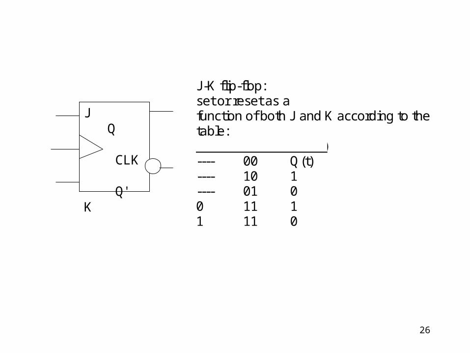
J Q CLK Q'K
J-K flip-flop:set or reset as afunction of both J and K according to thetable:Q(t) JK Q(t+1) ---- 00 Q(t)---- 10 1---- 01 00 11 11 11 0
27
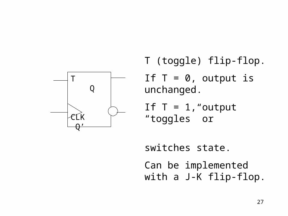
T Q
CLK Q’
T (toggle) flip-flop.
If T = 0, output is unchanged.
If T = 1, output “toggles” or
switches state.
Can be implemented with a J-K flip-flop.
28
Some uses of flip-flops:
Register. An n-bit register can be implemented withn D flip-flops.
Shift register. D flip-flops can also be used toimplement a shift register (left, right, orbidirectional).

29
Counter. An n-bit (up-)counter counts from 0 to2n - 1, A modular counter (which cycles back to 0)can easily be implemented with n JK flip-flops. Forexample, if n = 3, we have the pattern:
b(2) b(1) b(0) 0 0 00 0 10 1 00 1 11 0 01 0 11 1 01 1 10 0 0 etc.
Note that b(0) "toggles" on every clock cycle. Alsob(1) toggles whenever b(0) = 1 and b(2) toggleswhenever b(0) = b(1) = 1. We can use the followingpattern:

30
B(2)
B(1)CLK
B(0)
1
J Q
CLK
Q'
K
J Q
CLK
Q'
K
J Q
CLK
Q'
K
Clearly this same pattern can be extended to build ann-bit upcounter. Similarly, we can also use JK flip-flops to construct a downcounter.
31
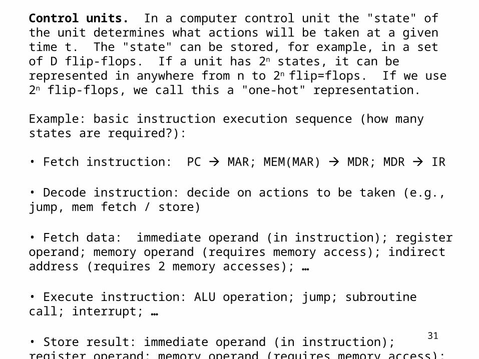
Control units. In a computer control unit the "state" of the unit determines what actions will be taken at a given time t. The "state" can be stored, for example, in a set of D flip-flops. If a unit has 2n states, it can be represented in anywhere from n to 2n flip=flops. If we use 2n flip-flops, we call this a "one-hot" representation.
Example: basic instruction execution sequence (how many states are required?):
• Fetch instruction: PC MAR; MEM(MAR) MDR; MDR IR
• Decode instruction: decide on actions to be taken (e.g., jump, mem fetch / store)
• Fetch data: immediate operand (in instruction); register operand; memory operand (requires memory access); indirect address (requires 2 memory accesses); …
• Execute instruction: ALU operation; jump; subroutine call; interrupt; …
• Store result: immediate operand (in instruction); register operand; memory operand (requires memory access); indirect address (requires 2 memory accesses); …
32
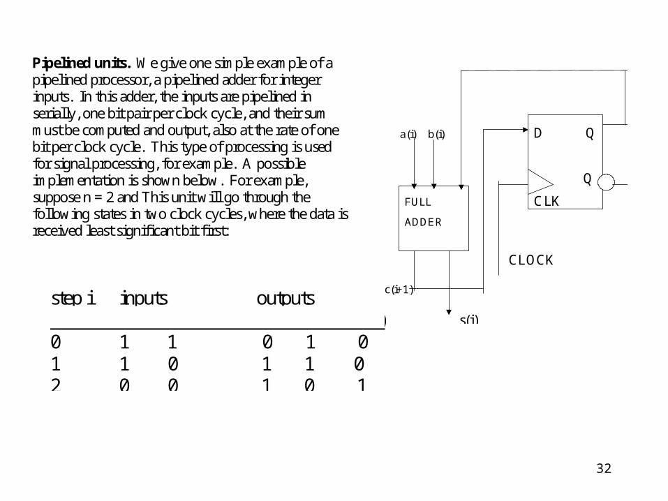
Pipelined units. We give one simple example of apipelined processor, a pipelined adder for integerinputs. In this adder, the inputs are pipelined inserially, one bit pair per clock cycle, and their summust be computed and output, also at the rate of onebit per clock cycle. This type of processing is usedfor signal processing, for example. A possibleimplementation is shown below. For example,suppose n = 2 and This unit will go through thefollowing states in two clock cycles, where the data isreceived least significant bit first:
step i inputs outputs a(i) b(i) c(i) c(i+1) s(i) 0 1 1 0 1 01 1 0 1 1 02 0 0 1 0 1
a(i) b(i)
CLOCK
c(i+1)
s(i)
D Q
Q'
CLKFULL
ADDER
33
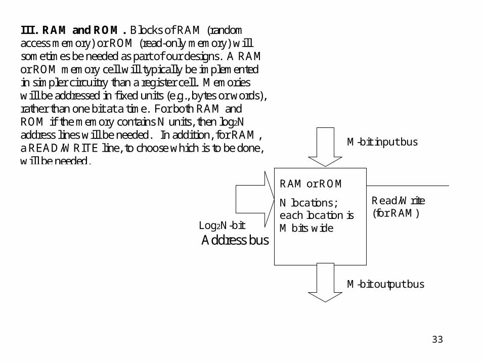
III. RAM and ROM. Blocks of RAM (randomaccess memory) or ROM (read-only memory) willsometimes be needed as part of our designs. A RAMor ROM memory cell will typically be implementedin simpler circuitry than a register cell. Memorieswill be addressed in fixed units (e.g., bytes or words),rather than one bit at a time. For both RAM andROM if the memory contains N units, then log2Naddress lines will be needed. In addition, for RAM,a READ/WRITE line, to choose which is to be done,will be needed.
M-bit input bus
Read/Write(for RAM)
Log2N-bit Address bus
M-bit output bus
RAM or ROM
N locations;each location isM bits wide

34
IV. I/O. The actual construction of I/O cells can bequite complicated. For now we will just assume thatan I/O cell can handle 1 bit and is either input-only,output-only, or bidirectional. Later we will lookmore closely at I/O implemented in the Altera tools.

35
Basic architectures:
• finite state machines, stack machines, Turing machines
• common parallel and distributed models

36
Basic types of machines:
1. Finite State Machine (FSM)
2. Stack Machine
3. Turing Machine / “Random Access Machine”/ Sequential Computer
4. Multiprocessor Machines

37
1. fsm--"finite state machine"--states, input, output; transition fromone state to the next is a function of current state or current state +input. Machine does not "remember" where it has been previously--you cannot look back at where you have been.
2 basic types:Moore machine: output from state machine is inMealey machine: output based on state you are in and input
Examples: vending machine, control unit, counter.
0 0,1 1 1
START 0
Can be realized by flip-flops and combinational logic (and I/O).
Theory: FSM regular languages
AB
C
38
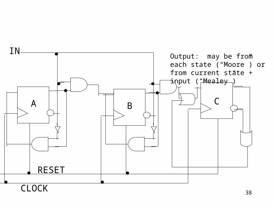
IN
A
CLOCK
CB
RESET
Output: may be from each state (“Moore”) or from current state + input (“Mealey”)
39
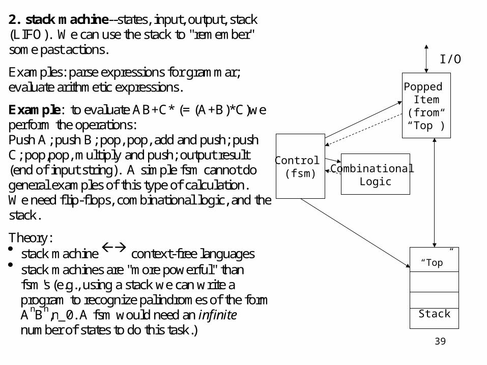
2. stack machine--states, input, output, stack(LIFO). We can use the stack to "remember"some past actions.
Examples: parse expressions for grammar;evaluate arithmetic expressions.
Example: to evaluate AB+C* (= (A+B)*C)weperform the operations:Push A; push B; pop, pop, add and push; pushC; pop,pop, multiply and push; output result(end of input string). A simple fsm cannot dogeneral examples of this type of calculation.We need flip-flops, combinational logic, and thestack.
Theory: stack machine context-free languages stack machines are "more powerful" than
fsm's (e.g., using a stack we can write aprogram to recognize palindromes of the formAnBn,n>0. A fsm would need an infinite number of states to do this task.)
Control (fsm)
“Top”
Stack
Popped Item
(from “Top”)
Combinational Logic
I/O

40
3. Turing machine or "random access machine" or sequentialcomputer--this in turn is more general than the stack machine. Itcan be realized by flip-flops, combinational logic, and a "randomaccess memory" in which each memory location can be accessedthrough its unique address:
(solid arrows represent control flow; dotted arrows represent dataflow).(Sometimes called a Single Instruction Single Data or SISDmachine).
Theory: "UTM": Universal Turing Machine--can execute anyalgorithm, model any classical computerTuring machine recursively enumerable languages
CONTROL
(FSM)
I/ORAMALU(comb)
(Actual “RAM” Hierarchy)
Registers
Cache
Main Memory (RAM)
(Virtual Storage)
{Hard Disk, Secondary Devices}

41
4. Multiprocessor Machines: combinations of the above machines may work together to provide more powerful processing.
Examples:
ControlTuring
Machine
ALU+RAM ALU+RAM ALU+RAM ALU+RAM
Vector Machine (“SIMD”) (ex. application:differential equations)
Turing Machine
Turing Machine
Turing Machine
Net-WorkedorDistri-butedProcessors(“MIMD”)(ex. applica- tion:databases)
Turing Machine
Turing Machine
Turing Machine
Turing Machine
Pipelined Processors (“MISD”) (ex. application: signal processing) Printer Graphics
SoundTypical PC
CPU
42
Homework: "building a computer"—questions?