1 Backup Options & Sample WAN Designs. 2 Chapter Topics WAN Backup Design Options Sample WAN...
32
1 Backup Options & Sample WAN Designs
-
Upload
hortense-townsend -
Category
Documents
-
view
220 -
download
2
Transcript of 1 Backup Options & Sample WAN Designs. 2 Chapter Topics WAN Backup Design Options Sample WAN...

1
Backup Options & Sample WAN Designs

2
Chapter Topics
WAN Backup Design Options Sample WAN Designs

3
Dial Backup Routing Dial-up WAN technologies continue
to see use today SOHO WAN connectivity Backup purposes
Designer can ensure connectivity between sites in the event of the failure of the main circuit
Configure routers to monitor the main circuit
If there is a failure, the backup line initializes and provides WAN connectivity
Terminate the backup when main circuit comes back online

4
Dial Backup Example

5
How Dial Backup Works
Use Figure 7-1 as a reference: Failure between Routers A & C Router C has an interface configured for
backup This device is notified of the circuit failure
between A & C Router C selects the backup ISN interface to
establish a connection with B Routing Protocol recalculates the paths to
route traffic When connectivity between A & C is
reestablished, link between B & C is terminated

6
Permanent Secondary WAN Link
This design features more than just the advantage of a redundant backup It also provides additional bandwidth Secondary link can be used for load
sharing Use floating static routes and routing
protocols to ensure that the link is actually a valid path

7
Permanent Secondary WAN Link
Cost of this design is often prohibitive for organizations design might also require more robust
networking equipment and expertise providing a permanent backup
connection for every main link is not financially practical in some situations

8
Shadow PVC
service provider provisions the network with a secondary PVC possible that a service provider will not
charge for this additional circuit as long as the load on it remains below a defined level
Much expertise is required when configuring a shadow PVC must ensure the load on the secondary
virtual circuit is kept to a minimum

9
Internet
“Best Effort,” arrangement No bandwidth guarantees
Security is a significant concern. Many options for implementing the
Internet as a backup option IP routing without constraints GRE tunnels IPSec tunnels

10
Internet
Both GRE and IPSec methodologies rely upon tunneling to transmit data over the public Internet Network-layer tunneling involves one
Layer 3 protocol transporting another Layer 3 protocol over the network
usually in a secure fashion

11
GRE
Defined by IETF RFC 2784 Tunnels IP over other IP networks Suits small- to medium-sized
Internet backup solutions that do not require the greatest degree of security
Suits solutions that use protocols incompatible with IPSec.

12
GRE

13
GRE
Functions of GRE – Figure 7-2 Network designates packets for
transmission across the backup GRE tunnel
packets already contain additional information by way of encapsulation
ingress router further encapsulates the packets with a new GRE header
router places the packets into a tunnel packets now feature a destination address
of the egress router

14
GRE
packets arrive at the egress, and this router strips away the GRE encapsulation information
Network equipment forwards the packets, which now contain the original IP headers and destination address information

15
IPSec
Also provides for tunneling IP over IP networks provides security for these transfers functions at the network layer encapsulates and authenticates IP
packets between IPSec routers

16
IPSec
Features and benefits Data confidentiality.
Cisco routers encrypt packets prior to their transmission across the network.
Data integrity. Receivers can authenticate packets sent
from an IPSec sender. Ensures that the data has not been
altered during transmission.

17
IPSec
Data origin authentication. Receivers can authenticate the source of
IPSec packets. Antireplay attacks.
Cisco routers can detect and reject replay attempts.
Simple deployment for network implementers.
Intermediate systems, such as the backbone (ISP) systems, do not require changes.

18
IPSec
Completely transparent to the applications running in the network.
Utilizes Internet Key Exchange (IKE) Automation of security key management.
Interoperates with the public-key infrastructure (PKI).
Compatible with GRE if necessary.

19
Sample WAN Designs

20
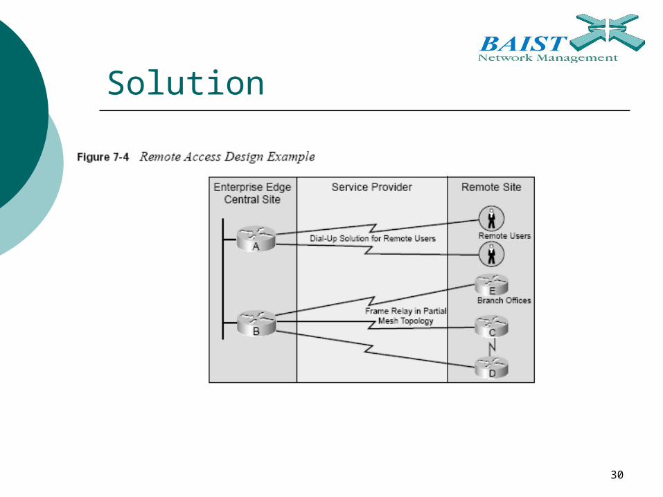
WAN Technologies for Remote Access
This network needs WAN remote-access solutions to accommodate remote users of the network and small offices that do not require constant access.

21
WAN Technologies for Remote Access The designer in this example has gained the
following information: The branch-office users should be able to access the
central site network seamlessly—as if the users are in that actual network.
The remote users need to access the network sporadically to check for e-mail notifications and transfer reports that are typically under 200 KB in size.
The branch-office locations require more consistent file transfer access and interactive traffic transfers. Low to medium volume is expected.
Two of the branch offices often need to share data directly with each other. This data is mission critical compared to other traffic sent by the branch offices.
The client has indicated no performance specifics for the network.
22
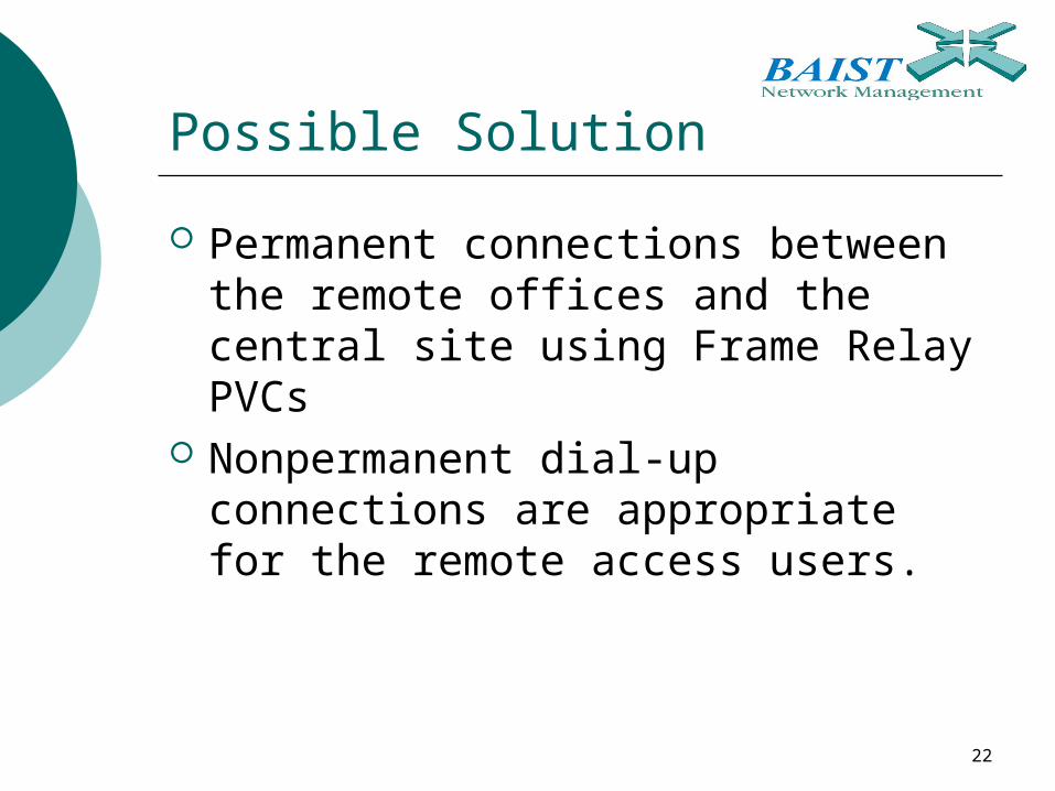
Possible Solution
Permanent connections between the remote offices and the central site using Frame Relay PVCs
Nonpermanent dial-up connections are appropriate for the remote access users.

23
Packet-Switched Network Designs
With regards to the scenario, designer must decide upon the specific Frame Relay topology
Packet-switched networks have three basic designs Star topology Partial-mesh topology Full-mesh topology

24
Star Topology
Specifies a core router that serves as the hub for the WAN connections hub-and-spoke topology
Core router connects to each of the branch offices branch offices can only communicate
with each other if they pass their communications through the core (hub) router
Simplified and centralized management

25
Star Topology
Not without its problems and disadvantages The central hub router represents a
single point of failure in the design. If this router fails, WAN communications across all the branch offices are affected.
Overall performance of the WAN relies upon a single point. This single point is the hub router; all traffic must pass through this potential bottleneck in the design.

26
Partial-Mesh Topology
Virtual circuits that connect many but not all the routers
Reduces the number of routers in the topology that require direct connections to each other
Design might have several “core” or hub routers that act as collection points for non-meshed routers to reach each other

27
Partial-Mesh Topology
Advantages to the partial mesh topology include Improved performance Improved redundancy Fewer virtual circuits than full-mesh
designs Disadvantages of a partial mesh
topology include Potentially a greater number of virtual
circuits than a star topology A greater level of expertise

28
Full-Mesh Topology
Each node connects to every other node in the network design
The greatest level of redundancy and performance
Approach is nearly impossible in very large networks due to cost concerns

29
Full-Mesh Topology Advantages of a full-mesh topology
include Best possible redundancy Best possible performance when configured
properly Disadvantages include
Large costs due to the number of virtual circuits required. There is one for every connection between routers.
They typically require large numbers of packet and broadcast replications for transmission to all locations in the network.
Configuring routers in full-mesh environment is quite complex—especially in environments with no multicast support.
30
Solution

31
A WAN ConnectingEnterprise Sites
Central site might consist of two facilities that are geographically disparate Must connect these two sites using
WAN technology to make them appear as one seamless network
Users must be able to access the resources of each site as if they were one site

32
A WAN ConnectingEnterprise Sites
Designer might recommend the provision of a high-speed point-to-point connection using Synchronous Optical Network (SONET) and Synchronous Digital Hierarchy (SDH) Speeds at 155 Mbps or much greater,
up to 10 Gbps Costs of this technology depend almost
entirely on the bandwidth required and the distance between the two sites