1 Atlanta's New Coliseum page 9 2 Children's Hospital page ... · of fabricated structural steel....
18
1 Atlanta's New Coliseum 2 Children's Hospital 9 Studio 011 Stilts page 9 page 11 page 15
Transcript of 1 Atlanta's New Coliseum page 9 2 Children's Hospital page ... · of fabricated structural steel....

1 Atlanta's New Coliseum
2 Children's Hospital
9 Studio 011 Stilts
page 9
page 11
page 15

MIIDERN CIINSTRDCnllN Publ ished by
American Institute of Steel Construction 1221 Avenue of the Americas New York, N.Y. 10020
O .... IC.RS
Van W. Coddington, President D. B. Hughes,
First Vice President George W. Hall,
Second Vice President Robert P. Stupp, Treasurer John K. Edmonds,
Executive Vice President Leslie H. Gillette,
Assistant Executive Vice President William W. Lanigan,
Secretary and General Counsel
8DITORIAL STA""
Daniel Farb, Director of Publications Mary Anne Stockwell, Editor
RaOIONAL a .... le ••
Atlanta, Georgia Birmingham, Alabama Boston, Massachusetts Chicago, Illinois Cleveland, Ohio Columbus, Ohio Dallas, Texas Denver, Colorado Detroit, Michigan Charlotte, North Carolina Hartford, Connecticut Houston, Texas Los Angeles, California Memphis, Tennessee Milwaukee, Wisconsin Minneapolis, Minnesota New York, New York Oklahoma City, Oklahoma Omaha, Nebraska Philadelphia, Pennsylvania Pittsburgh, Pennsylvania St. Louis, Missouri San Francisco, California Seattle, Washington Syracuse, New York Washington, District of Columbia
VOLUME XV I NUMBER 1 I FIRST QUARTER 1975
CONTENTS
Atlanta's New Coliseum A Lightweight Hi Rise A Children's Hospital in Philadelphia Two-Way Trusses for a High School Gymnasium Studio on Stilts
1975 T. R . HIGGINS LECTURESHIP AWARD
3 6
11 13 15
Mr. E. Alfred Picardi has been named l'ecipient of the Fifth Annual T. R. Higgins Lectul'eship AtVal·d. Mr. Pical'di was chosen to l'eceive the $2,000 awal'd for his contl'ibution to the fund of engineering knowledge as the OJUthor of UStmctuml System-Standal'd Oil of Indiana Building" (ASCE Journal of the Struc/uml Division, April 1979).
The award will be presented at the 1975 National Engineering Conference banquet on Thul'sday evening, May I, in St. Louis.
1975 PRIZE BRIDGE COMPETITION
•
Entl'ies are invited for the 47th Annual Prize Bridge Competition to select the most beautiful steel bridges opened to traffic . dU1'ing the calendal' yeal·1974.
The members of the 1975 Prize Bl'idge Jury are: Ruben N. BergendoD, F.ASCE Howard, Needles, Tammen & Bergendoff, Kansas City, Missouri Arlhur J. Fox, Jr., F.A CE President-elect, American Society of Civil Engineers; Editor, Engineeloing NewsRecord, New York, New York John M. Haye>, F.ASCE Professor, School of Civil Engineering, Pltrdue University, West Lafayette, Indiana William N. Holway, F.A CE Executive Vice-President, Benham-Blair & Affiliates, Inc., Tulsa, Oklahoma Nellon C. /one., F,A CE Assistant Deputy Director (Retil'ed), Michigan Highway Departrnent, East Lansing, Michigan
Entlies must be postmarked prior to May 91, 1975 and addressed to the Atoards Committee, American Institute of Steel Constrltction, 1221 Avenue of the Americas, New York, New York 10020.
1975 FELLOWSHIP AWARDS
FoU1' engineering students have been awarded $3,500 fellowships in the 19th Annual Fellowship Awards Program. The progra71l is designed to enCOU1'age expel·tise in the creative use of fabricated structural steel.
Bruce C. Barrell Brigham Young University Aldo F. Colandrea University of Detroit Daniel B. Goeheilel California State University at North- .
ridge Gary R. Kuhn Arizona State University
.... .... 0.. :l> Q = '" C>. '" .... en ... Q)
Q) ("") '< .... ("") .... ::r rT1
Q) Q) ::2 ("") = :::l G:> 0..
'" ::2 c. "'"' rT1
'" '" .... ,." :::I c: :;0 < "'"' '" :::I ::2 0 G:> "C ~
'" 0 c::: :;0
• ::2 :l> r--
• Please enter my subscription to the AISC ENGINEERING JOURNAL
U. S. and Canada 1 Year $500
3 Years $12.50
Other Countries
1 Year $ 6.00 3 Years $15.00
·Payable 10 U. S. Funds
Payment must be enclosed with this order. Make checks payable to AISC .
.... , (plene prmt )
fiRM OR .AffiLIATION
ADORE-55
'< -i 0 0 c: "'"' '" V> :::l c: .... c- '" "'"' V> ("")
"'"' -C. .... o · :::l .... 0 .... = '"
CITY STAn liP CODE
Prolession or occupation
[) Engln'" (J Architect o Educator (J Other

• • - •
Q) • Q) CI) ~ Q) "'CI c.,:) CI) :.... Q)
C = Q) U) , = ~ -Q btl u c < .- = ~ CI) :.... = Q)
~ Q) ~ Q -= "'CI CI) ~ - --
• dlZ AH1Nno~ 31V1S
BUSINESS REPLY MAIL NO POSTAGE STAMP NECESSARY IF MAILED IN THE UNITED STATES
- POSTAGE WILL BE PAlO BY-
AMERICAN INSTITUTE OF STEEL CONSTRUCTION 1221 Avenue of the Americas
New York. New York 10020
Attention: Paul R. Johnson
c:.::s :z:: -c::: ....... U..I < U..I :z:: :z:: - c::: c:.::s =» :z:: c U..I -
A11~
smoov
WOHl
fiRST CLASS
PERM IT No. 62038
N£W YORK , N. Y.
0

• by James R. Fincher
. ATLANTA'S NE~ COLISEUM The challenge of designing an eco·
nomical structure to clear-span a square 350 ft on a side, resting on walls 100 ft high, is not to be taken lightly. Add to this a restriction that two·way trusses are not acceptable because of appearance and that the facility must be op· erating in less than two years, and the problem becomes formidable. Mr. Fincher is Pres ident" Quo Modo, Inc . and Sr.
AssOCiate, prybrlOwSkl and Gravino, Inc., At· lanta, Ga., struc ural engineers for this project .
Basica lIy the problem was to provide the design for a sports coliseum - the Omni in Atlanta, Ga. - to accommodate 16,000 seats for professional hockey and basketball games, as well as to house other activities such as ice shows, concerts, and conventions. The loca t ion of the site, hemmed in by vehicular viaducts and railroads, was a strong determinant for a square build· ing configuration. The architect cen·
,
tered the seating "bowl" on the diag· onals of the 350·ft square plan to pro· vide advantageous sight lines for all seats. This seating arrangement set the plan size as well as the form and height of the wall trusses.
Roof Structure Studies of various structural schemes
consistently revealed that a two·way truss roof system would be highly de·

The Onmi Coliatum, Atlallta, Ga., can accommodate ItP to 16,000 people.
sirable. However, the owner required that the structure not only provide a dramatic ceiling to the space, but that the roof be visually interesting and attractive when viewed from the tall office buildings surrounding the site. Consideri ng the owner's restrictions, as well as the need for economy, the required solution appeared to be one of devising a steel two-way truss that did not look like a two-way truss.
The final design solution - one that satisfied both the aesthetic and economic criteria of the owner - was a unique space truss conceived as an orthogonal intersection of trapezoidal folded plates connected by diagonal upper chord members.
4
To visualize the resulting structure, consider a chess board having only seven rather than eight squares to a side. Begin at one corner square and place on every alternate square (say black) a truncated pyramid about half as high as the plan dimension of the black squares. Leave the red squares as flat surfaces, then connect the top corners of adjoining truncated pyramids with diagonal members (see the schematic drawing of the roof plan and elevation).
Because the roof was required to rest on approximately 100-ft high walls, erection was a major consideration. Lifting a small number of completed large substructures was selected as the
erection scheme. The truncated pyramids, called "pods," were ideally suited for such a scheme; framed with steel, they were light in spite of their large overall dimensions (50-It square at the base, 25-1t high).
The schematic drawing of a typical pod shows the arrangement of the steel framing. Although steel sizes varied with load requirements, all base members were wide flange sections, while diagonal members and braces were pipe sections.
As in any space structure, the con· nections make the difference in a prac- • tical, economical, and safe structure. Great attention was paid to the connection details and many comparative
MODERN STEEL CONSTRUCTION

, r
V1
•
•
P O D F R A M I N G SC H E MATI C
/\/ ---.
<~> 0; ,:: s
/ /~ 1
50 Feet
Plan
~
• • ~ ~
~ Elevation
ROOF SCHI: M ATrC
~Ml "'_~
- I
Plan
FIRST QUARTER 1975
studies were made. Fully welded pods, partially shop fabricated and then field assembled by welding in a special jig, was the only scheme that satisfied all requirements. For example, a typical bolted joint would have required 300 1'I4-in. diam. A490 bolts and would have undoubtedly required expensive field ream ing because of the thick materials being joined.
Some welding problems were encountered, but they were solved by attention to normal good practice of proper joint design, good joint preparation and fit-up, and competent, qualified welders.
Both the pods and the squares of flat roof deck were covered with a weathering steel exterior finish.
Wall Trusses The form of the supporting wall
trusses, approximately 100 ft high, was determined by the intersection of the seating bowl (see the schematic diagram of the wall trusses). The combination of this strong central tower section and cantilevered ends was then used
to advantage both structurally and architecturally. The tower was ideal for resisting wind forces, while the normal tendency of the cantilevers to deflect applied reverse forces to the roof structure.
Architecturally, in the corners beneath the seating bowl, four glass enclosed lobbies were formed by the 100-and 150-ft cantilevers of the wall trusses, the 45-ft high glass curtain walls being framed with light steel trusses to resist wind forces. The exterior of the building was sheathed in weathering steel with feature strips applied to the surface identifying the structural frame of the wall truss.
The completed structure satisfied the initial criteria of an economical design having pleasing appearance both from the outside and from the spectator's viewpoint. The structural weight of the roof was approx imately 16 psf, which compared most favorably with a twoway truss system at about 23 psf. Thus, a higher in-place unit cost was offset and the "premium" for appearance was negligible.
Architect: Thompson, Ventulett & Stainback Inc. Atlanta , Ga.
Structural En"ineer: Prybylowskl and Gravino, Inc. Atlanta , Ga.
General Contractor: Ira H. Hardin Company Atlanta, Ga.
Steel Fabricators: Mississippi Valley Structura l Steel Divis ion of Debra" Corporation Chattanooga , Tenn. Steel Inc., Scottsdale, Ga .
WALL TRU S S S C HEMATI C
/\ /\ /\
PI""
- lt18 FHt
100 Feet '"I- ~ _! ~1023 Feet
Elevat Ion
5

A LIGHTVVEIGHT by Stanley Goldstein
Major high-rise building requlflng 36 percent less steel than any other structure of comparable size was achieved through structural design that was consciously directed toward economy. Use of high-strength steel, composite design and lateral stability systems designed and refined by analytical modeling with the aid of a computer were the primary methods of accomplishing this remarkable savings in material.
6
Located in windy downtown Boston, the 100 Summer Street tower (Blue Crossl Blue Shield is a major tenant), which utilizes only 12V4 Ibs of structural steel per sq ft, reflects a major breakthrough in high-rise framing economy. This exceptionally low weight was determined by the developer, Cabot, Cabot & Forbes, based on the actual total steel tonnage supplied.
Overall plan dimensions are 180 ft x 240 ft and the structure rises 33 stories (420 ft). A 40 It x 90 It central core contains elevator, duct, pipe and electrical shafts as well as a lobby, toilets, and stairways. Deep notches intruding on both north and south facades form a critical part of the massing of
Mr. Goldstein, consulting structural engineer on th is project! is partner.in·charge of LeMessutier Associates/ SCI's New York office.
HI RISE
the building, which in combination with the bronze-tinted aluminum skin won approval of the vigilant Boston Redevelopment Authority.
Since the tenant for the lower half of the building required electrifiable floors, a 3·in. deep blended metal deck was provided for these floors, while 1 V2-in. deep metal deck was used else· where. All metal deck is composite and topped with a minimum 3%-in. of lightweight concrete, achieving a two-hour fire rating without spray fireproofing.
Structural requirements for this building are not unusual. Mechanical rooms are located at the 9th, 27th, and 33rd levels, and a computer floor at the 11th level has a 150 psf live load.
•
•
There are provisions for an offstreet • truck loading space and a cafeteria is located on the second level. Roofs at
MODERN STEEL CONSTRUCTION

•
the 29th and 32nd levels have been designed to support paving and a 100 psf live load. In addition to wind loads, the Boston building code requires design for Zohe 2 seismic loads.
Economical Structural Design The structural design was consciously
directed toward economy by considering the system as having three primary components, columns, lateral stability systems, and framing.
Column economy is achieved by us· ing high strength steel (Fy= 50 ksi), by eliminating as many columns as possible from the lateral stability system (allowing them to be designed for direct load only), and by providing a trussed lateral stability system that enabled the designer to use the effective length factor K= 1.
FI RST QUARTER 1975
Lateral Stability System Due to the combination of wind and
seismic loads, the achievement of lateral stability system economy appeared at first to be somewhat difficult, since wind forces are usually best resisted by stiff members while seismic forces are often best resisted by more flexible (ductile) systems. In total , the system must provide the following,
1) Stability against overturning
2) Strength against lateral forces
3) Strength and stiffness to brace the column system
4) Stiffness against lateral forces
5) Torsional strength and rigidity
Bracing trusses were installed in the core between elevator, duct and stair-
way shafts. East-west diagonals were spread apart to permit access to elevator lobbies. As low-rise and mid-rise elevator shafts terminate at the 16th and 24th levels, truss lengths decrease accordingly. The bracing trusses are complemented by moment·connected portal frames located in the east and west facades and along column lines 5 and 11.
These portal frames serve several purposes, (a) they provide the reserve ductile strength required by earthquake regulations; (b) they augment the trusses in resisting wind and earthquake forces, particularly at the top of the bu i lding, greatly reducing the overturning moment on the trusses; and (c) they provide great torsional strength and rigidity at no additional cost, since they are located far from the centroid.
7

Steel Framing Framing economy is achieved by
combining high-strength steel and composite design with a small typical bay size of 20 ft x 25 ft. Composite design of girders also provided more clear space for ducls, permitting a 12 ft-O in. story height to be maintained. Since shear studs were placed on girders only, melal deck was spread apart at the girders to permit the use of Ye- in . diameter studs rather than the less efficient '!ii-in. studs required when welding through metal deck.
Almost all of the steel used for this project was ASTM A572, grade 50. Exceptions were the use of A36 for portal frames and A588 for thick plates. Shop connections were welded, while field connections were high-strength bolted. Portal frame columns were spliced 3 ft-6 in. above the floor to eliminate the need for special moment connections.
Computer Design Lateral stability systems for the
building were designed with the aid of an IBM 1130 computer. In order to obtain maximum understanding and control of the linked truss-portal systems, analytical modeling, both with respect to the number of stories and the number of elements, was performed. Curves of acceptable lateral displacements were developed as criteria for each direction. Preliminary steel sizes were selected for the entire lateral stability system.
The system was then analyzed by the computer and its deflections compared with the criteria, and the steel members were adjusted accordingly. The computer calculated influence lines so that optimum efficiency could be obtained. This process (called "tuning") was repeated more than 10 times in each direction until the optimum was selected.
The resulting structure required only 61 percent as much steel as is usually required for a 33-story structure. To the best knowledge of the structural designers of this building, the lowest previous weight per sq ft documented for a building of this size was 19.1 psf (see Modern Steel Construction, First Quarter, 1972). Fabrication and erection were normal, so that the owner reaped the full benefit of the dollar value of the material saved, besides the value of the lower story height required.
8
I -
~ TYP
TYP
F ITTEC STlFf'EllifR It'. EQUAL TO GIRCE't FLANI!E THICI(N[SS (eoT" "OES)
Tvpical portal/rame moment conn~ction
SECT. A-A Elevation-wind trull'
GUS51n .It
PROVIDE CO\..UM"'" STIFfENER!> (I' RfO'O.)
AL.L Ce».NECTIONS .4490 H 5 eoLT5 - 'AtC'TlOf\,' "NI'E.
Architect, Welton Becket and Associates New York, N.Y.
Structural Enaineer: LeMessufler Associates/SCI New York, N.Y.
General Contractor: Aberthaw Construction Company Boston, Mass.
Steel Fabricator: Harris Structural Steel Co., Inc. Piscataway, N. J.
SECT.B-B Wind truBS de tail
MODERN STEEL CONSTRUCTION
•
•
•

•
W lti.S I W l~. S I
WI(8;"," WI(h!t l WI It~ \
Momentwconnccted portal/rames
Wind trusses
FRAMING PLAN (8TH FLOOR)
FIRST QUARTER 1975
------+---- ---r-------+-------~~2
.. ~ ': ~---! ~ . '!!
• " •
----+-+<.
-_~t='c:;'=':!' !:;i·;:;==::i"'k:::±::.W;;;IO~I·=<·;=O=~H==:W='·"'~"f_-==iIl---'-~i.: W16.tl W16.~1 WI'."
9


•
•
•
A CHILDREN'S
HOSPITAL in Philadelphia
by William J. H. Hough, Jr., AlA
FIRST QUARTER 1975
A nine·story landscaped central court· yard, topped with a transparent roof, dominates the Children's Hospital of Philadelphia, an all·comprehensive fa· cility that dually serves as a major reo search center and as the pediatric teaching unit for the University of Pennsylvania School of Medicine.
Salconies at all nine levels surrounding the 100 ft x 100 ft court provide play, lounge, and staff areas. Half of all patient rooms and all dining areas also enjoy views into the court. The courtyard acts as a return air plenum for the Hospital's unique energy reclaim system.
Energy Recla im System Children's Hospital is the first major
hospital in the country to be heated and cooled by an energy reclaim system
Mr. HOUih is • partner of Harbeson HoUSh Uvin&ston & Larson, Architects and Planners, Phil· adelph •• , Pa .
IJ

that recycles heat from people, equipment and solar energy. The system also minimizes the escape of pollutants into the environment, using the maximum in previously wasted natural energy, purifying polluted air, and recycling heat for reuse.
General Features The new 900,000 sq ft structure,
with provision for expansion, serves patient care, medical education, and research functions. Two floors below grade provide parking space for 400 cars as well as for ancilliary and support services. The ground floor includes a chapel, branch bank, post office, gift shop, sidewalk cafe, and an auditorium seating 335 people. The out-patient department, located on the first three floors, accommodates 200,000 visitors annually. The roof contains a helipad serving the emergency transport system.
Research facilities are arranged on a modular system so that they can be adapted to shifti ng needs. Flexibility is provided by mechanical corridors which supply all services from electricity to oxygen, and each laboratory is able to simply " plug" into the needed services.
The interiors are uniquely designed for chi ldren, from furniture scale and primary colors to the provision for play programs, school facilities and procedures and techniques adapted to the special tolerances of infant, child, and adolescent. The hospital has an informal domestic atmosphere with low ceilings and bright graphics_
Steel Framing Steel was chosen as the basic struc
tural material because it met the following criteria: ease of acceptance of extensive mechanical and electrical systems, adaptibility to future addi t ions and alterations, compatibility with architectural and first costs, and the many and varied programmatic demands developed by the owner. The subsequent use of steel decking with dovetailed ribbing also relates well to these criteria .
The basic structure is a computerdesigned steel frame utilizing a 24-ft x 48-ft bay with infill beams also chosen by plastic design methods. The principal connections were welded for continuity. The use of steel was entirely consistent with the architects' desire to clad the building in lightweight cur-
tain wall materials and to expose the . structure wherever possible for economic and aesthetic reasons, as well as to provide fascinating eye-appeal for the young occupants of the building, their parents, and the staff.
The large and carefu lly exposed steel trusses in the nine-story centra l court, the frank expression of tension members with their turnbuckles and other fittings for the hanging balconies within the cou rt, and the extensive use of open steel grati ng in the five-story mechanical corridor demonstrate the aesthetic and economic benefits which can be derived from the use of steel .
Architects: Harbeson Hough Livingston & Larson William A. Amenta Associated Architects Philadelph ia, Pa .
Structural Engineer: A. W. Lookup Company Philadelphia, Pa.
General Contractor: Baltimore Contractors, Inc. Baltimore, Md .
Steel Fabricator: • Bristol Steel & Iron Works, Inc. Richmond, Va.
£11- r r L
I
I F CHILD
RESTAURANT
CENTR: i. STERIUZING ~
1
THE CHllORENS HOSPITAL OF P HILAOELPHIA
12
~
PATIENT CIIRE
PATIENT CARE
PATIENT CARE
INTENSIVE 'CARE ~ I
,1 T SURGIZAL CLlNI~~ ,
l ~t1 MEDICAL CLINICS l ~ EMEROi..cY ;';- BANK!L ~
~ PARKING
PARKING
NORTH SECT ION •• .. II .... !'I!i-e
MOOERN STEEL CONSTRUCTION
• j

•
• Two-Way Trusses for a
•
HIGH SCHOOL GYMNASIUM by Frederick M. Law
Arch itect: Arthur Rigolo Clifton, N. J.
Structural Engineer: Kellerman & Dragnett, Inc. Little Falls, N. J.
General Contractor: Senia Construction Company Franklin Lakes. N. J.
FI RST QUARTER 1975
Perhaps t he clearest expression of the structural engineer's art is the roof framing system of a modern high school gymnasium. Invariably, this completely visible structural system is one of the dominant elements in the tota l composition.
Although a number of di fferent structu ral systems have been used to frame gymnasium roofs in recent years, the simple roof truss remains the one most often selected because of its high degree of structura l efficiency. However, this eff iciency is accompanied by an unattract ive maze of lateral bracing between roof trusses. Fortunately, a solu· tion does exist that meets wi th aesthetic approval and proves more efficient as well-the two-way truss system.
Dr. Law, Chairman of the Department of Civil Engineering, Southeastern Massachusetts University , North Dartmouth, Mus., served as Structural Consultant with Kellerman & Dra~· nett, Inc., the structural engineers for this project .
Two-Way Truss System The two-way truss system carries the
load in two directions instead of one. This results in smaller member sizes and a lighter roof system. In addi t ion, no latera l bracing between trusses is required, thus achieving even more structural efficiency. Further, the trusses express a strong, clear statement of structural form which has universal visual appeal.
This combination of structural efficiency and clarity of the structural form led the designers to select two-way trusses to frame the roo f of the Lakeland Regional High School Annex Gymnasium, Wanaque, N. J.
To meet the criterion of dividing the gymnasium into separate use areas by means of sliding doors, one truss was placed along the centerline of the roof in both directions_ Space requi rements in adjacent areas of the annex dictated
13

the specific column locations. Additionally, the maximum span of the metal deck (and hence the spacing of the joists) led to the symmetrical, but uneven truss spacing.
Analysis of System Unfortunately, the analysis of a two
way truss system is not as simple as the clarity of its form might suggest. Such systems are always statically indeterminate, usually to a rather high degree. Therefore, an exact analysis requires the formulation and solution of a series of simultaneous equations - a time-consuming and complex procedure. It is probably this computational difficulty, more than anything else, which has discouraged the use of two-way truss systems.
In an attempt to overcome this difficulty, it was assumed that the system was statically determinate for the preliminary design. The total load on each tributary roof area at each truss intersection was divided equally between each of the intersecting trusses.
Admittedly, this assumption in no way attempts to consider the relat ive
........ ro
stiffnesses of the trusses. However, it is believed that the simplicity of the approach far outweighs any min imal loss in theoretical accuracy. Although it was not considered to be absolutely necessary by the author, a detailed analysis was made of the two-way truss system using the classical method of consistent deflections. The resulting member sizes for both analyses for each truss are indicated in Table 1 for comparison.
The method of consistent deflections requires: a) the formulation of deflection equations for each truss at each point of intersection in terms of the applied loads and the unknown interaction forces between trusses; b) the formulation of the compatibility equations which indicated that the deflection at each point of intersection is the same, whether approached from one direction or from the other; c) the formulation of the equilibrium equations for the system; and d) the simultaneous solution of the set of equilibrium and compatibility equations.
Taking advantage of the symmetries existing in the gymnasium, there were
-, .!!
---'
-~~~ 12H4' "-o"oe '0
-:' h , , mJitarJ -0 -s ~ N
T!lJSS T5
'0 , ~
~ .. ~ .!' • TlIUSS 14 l- • • ~
:I .. .. .. II J .. .. .. , ! T1!USST5 ~
, , E
~ ~ !' • -0
-' 0 N
"""S TO
LJ . ,
.!!
.
11''' 11- " '-(/ zo'- o- zo'-o' ~ L 107'- 10"
ROOf fRAMING PLAN
VSVSVSVSJZSV\l :! IO'T" . ~ ~~ PLAH ~~y ~ I~I
TYPICAL TRUSS ELEVATION tTl ~u Te)
'S! , -2
a total of 13 unknown deflections and 13 unknown interaction forces between intersecting trusses requiring the formUlation of a series of 13 simultaneous • equations. As formulated, they con-sisted of four equations of equilibrium and nine compatibility equations. The nine compatibility equations comprised combinations of deflections determined from a series of 22 separate deflection equations. A matrix inversion routine and an IBM 1620 computer solved the 13 simultaneous equations for the un-known interaction forces.
The finite difference method of analysis, a method frequently recommended for two-way truss systems, was considered for the analysis of the gymnasium roof. However, in order to gain advantage of ease in equation formulation, which the finite difference method yields, a flexural grid with approximately equal increments is required. In the case of the gymnasium roof, as with most real structures, the truss spacing was not equal in either direction, nor was the pattern the same in the two directions. Therefore, the finite difference method offered no advantage.
It is estimated that the use of the two-way truss system resulted in approximately a 20 percent savings of • structural steel compared with the use of the simple one-way truss and asso-ciated lateral bracing system. Further, for this type of relat ively small struc-ture, subjected to ordinary loads, the simple approximate analysis performed appears to lead to member sizes not differing significantly from the sizes determined by the more time-consuming exact analysis.
Tabl. 1 - Member Sizes
Ap,rOJ. Consistent "'ethod D,fllctlons
Trusl .hmtler M,m",r Slit Member Silt
Truss Tl Top Chord Bottom Chord Dilional
Truss 12 Top ChOfd Bottom Chord OIIIOMI
wall I waJ,31 2l51ll7/ 16
walll 2L7.4lt3/1 2l 4x3l3/ 1!1
W8>l' Wall31 2l5l3x7l16
wal3l 2l7l4x3/ a 215l3x1l16
Truss T3 Top Chord Wl.l1 W81124 Bottom Chord 2L6a4x3/ 8 216l415/ 16 Di"on.1 2l41ll15/ l6 2l41ll1S/ l6
Truss T4 Top Chord Wat31 BoUom Chord Wal31 01'10011 2l411ll / a
Trun T5 Top Chord W81l1 Bottom Chord 2l6.413/8 OI'IORII 2l4Jt313/ 8
Truss T6 Top Chord Willi Bottom Chord 2l714Jtl / 8 DI'IORII 2l411l3/ 8
Wal24 Walll 2l41l15/ l6
Walll 2l71l413/ 8 2l51317/ 16
W8124 2l61l415/ 16 2l41l31l5/ 16
MODERN STEEL CONSTRUCTION
•
'1
•
•
•
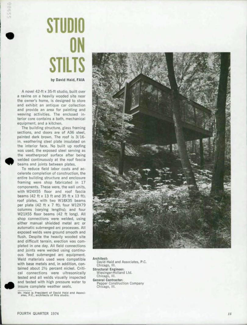
STUDIO ON
STILTS by David Ha id, FAIA
A novel 42-ft x 35-tt studio, built over a ravi ne on a heavi Iy wooded site near the owner's home, is designed to store and exhibit an antique car collection and provide an area for painting and weaving activities. The enclosed interior core contains a bath, mechanical equipment, and a kitchen.
The building structure, glass framing sections, and doors are of A36 steel, painted dark brown. The roof is 3/16-in. weathering steel plate insulated on the interior face . No built up roofing was used, the exposed steel serving as the weatherproof surface after being welded continuously at the roof fascia beams and joints between plates.
To reduce field labor costs and accelerate completion of construction, the entire building structure and enclosure framing were shop fabricated in 17 components. These were, the wall units, with W24X55 floor and roof fascia beams (42 ft x 13 It and 35 ft x 13 ft); roof plates, with two W18X35 beams per plate (42 ft x 7 tt); four W12X79 columns (varying lengths); and four W21X55 floor beams (42 It long). All shop connections were welded, using either manual shielded metal arc or automatic submerged arc processes. All exposed welds were ground smooth and Ilush. Despite the heavily wooded site and difficult terrain, erection was completed in one day. All field connections and joints were welded using continuous feed submerged arc equipment. Weld materials used were compatible with base metals and, in addition, contained about 2V2 percent nickel. Cri t ical connections were ultrasonically tested and all welds visually inspected and tested with high pressure water to insure complete weather seals.
Mr. Haid is President of David Hald and Associates, p ,e ., architects of this studio.
FOURTH QUARTER 1974
Architect: David Haid and Associates, P.C. Chicago, III.
Structural Engineer: Wiesinger-Holland Ltd. Chicago, III.
Genera l Contractor: Pepper Construction Company Chicago, III.
15

AMERICAN INSTITUTE OF STEEL CONSTRUCTION 1221 Avenue of t he Americas New York, N. Y. 10020
----Address Correction Requested
STUDIO ON STILTS (continued)
Upon completion of field welding, the floor construction (metal deck on the lower flanges of the floor beams, insula· tion and concrete slab) was installed. The sequence of construction put the vertical glass mullion bars in tension, thus transmitting a portion of floor load to the roof fascia beams, which for visual reasons are the same size as the floor fascia beams. This helped equalize deflections, particularly on the 42 It span. Because of the extreme length of the columns (20 It from the underside of the floor to base plate on the longest), additional lateral stiffness was achieved by using the entrance bridge as a diaphragm connected to the floor fascia beam and to a grade beam at the edge of the ravine.
The building is glazed with 'I4-in. bronze plate glass set in the steel framing. Interior finishes are a terrazzo floor, plaster ceiling and the core of painted wood panels.
BULK RATl US POSTAGl
PAlO
NEW YORK. N Y Permit No _ 6662 •
•
I • •