
1 © 2004 Cisco Systems, Inc. All rights reserved. RST-2602 9908_06_2004_X2 DEPLOYING MPLS-VPN...
96
1 © 2004 Cisco Systems, Inc. All rights reserved. RST-2602 9908_06_2004_X2 DEPLOYING MPLS-VPN SESSION RST-2602 Rajiv Asati ([email protected])
-
Upload
charlene-gilbert -
Category
Documents
-
view
225 -
download
2
Transcript of 1 © 2004 Cisco Systems, Inc. All rights reserved. RST-2602 9908_06_2004_X2 DEPLOYING MPLS-VPN...

1© 2004 Cisco Systems, Inc. All rights reserved.
RST-26029908_06_2004_X2
DEPLOYING MPLS-VPN
SESSION RST-2602
Rajiv Asati ([email protected])

222© 2004 Cisco Systems, Inc. All rights reserved.
RST-26029908_06_2004_X2
Agenda
• MPLS VPN Definition?Technology
Configuration
• MPLS-VPN Services Providing load-shared traffic to the multihomed VPN sites
Providing Hub&Spoke service to the VPN customers
Providing MPLS VPN Extranet service
Providing Internet access service to VPN customers
Providing VRF-selection based services
Providing Remote Access MPLS VPN
Providing VRF-aware NAT services
• Advanced MPLS VPN TopicsInter-AS MPLS-VPN
CsC Carrier Supporting Carrier
• Best Practices
• Conclusion.

333© 2004 Cisco Systems, Inc. All rights reserved.
RST-26029908_06_2004_X2
Prerequisites
• Must understand basic IP routing, especially BGP
• Must understand MPLS basics (push, pop, swap, label stacking)
• Must finish the evaluation
http://www.networkers04.com/desktop

444© 2004 Cisco Systems, Inc. All rights reserved.
RST-26029908_06_2004_X2
Terminology:
• LSR : Label Switch Router
• LSP : Label Switched Path
The chain of labels that are swapped at each hop to get from one LSR to another
• VRF : VPN Routing and Forwarding
Mechanism in IOS used to build per-interface RIB and FIB
• MP-BGP: Multi-Protocol BGP
• PE : Provider Edge router Interfaces with CE routers
• P : Provider (core) router, without knowledge of VPN
• VPNv4 : Address family used in BGP to carry MPLS-VPN routes
• RD : Route Distinguisher
Distinguish same network/mask prefix in different VRFs
• RT : Route Target
Extended Community attribute used to control import and export policies of VPN routes
• LFIB : Label Forwarding Information Base
• FIB : Forwarding Information Base (FIB)

555© 2004 Cisco Systems, Inc. All rights reserved.
RST-26029908_06_2004_X2
Agenda
• MPLS VPN Definition?Technology
Configuration
• MPLS-VPN Services Providing load-shared traffic to the multihomed VPN sites
Providing Hub&Spoke service to the VPN customers
Providing MPLS VPN Extranet service
Providing Internet access service to VPN customers
Providing VRF-selection based services
Providing Remote Access MPLS VPN
Providing VRF-aware NAT services
• Advanced MPLS VPN TopicsInter-AS MPLS-VPN
CsC Carrier Supporting Carrier
• Best Practices
• Conclusion.

666© 2004 Cisco Systems, Inc. All rights reserved.
RST-26029908_06_2004_X2
MPLS-VPN Operation’s Theory
• VPN definition: VRF instance
• VPN Route Propagation (Control Plane)
• VPN Packet forwarding (Data Plane)

777© 2004 Cisco Systems, Inc. All rights reserved.
RST-26029908_06_2004_X2
MPLS VPN Connection Model
PE
VPN Backbone IGP
MP-iBGP session
PE
P P
P P
PE routers
Edge Routers
Use MPLS with P routers
Uses IP with CE routers
Connects to both CE and P routers.Distribute VPN information through MP-BGP to other PE router with VPN-IPv4 addresses, Extended Community, Label
P Routers
P routers are in the core of the MPLS cloud
P routers do not need to run BGP and doesn’t need to have any VPN knowledge
Forward packets by looking at labels
P and PE routers share a common IGP

888© 2004 Cisco Systems, Inc. All rights reserved.
RST-26029908_06_2004_X2
MPLS VPN: Separate Routing Tables in PE
The Global routing table
Populated by the MPLS backbone IGP
In PE routers may contain the BGP Internet routes (standard ipv4 routes)
CE
PE
CE EBGP,OSPF, RIPv2,Static
vpn site 1
vpn site 2
MPLS Backbone IGP (OSPF, ISIS)
VRF routing table
Routing (RIB) and Forwarding table (CEF) associated with one or more directly connected sites (CEs)
The routes the PE receives from CE Routers are installed in the appropriate VRF routing table(s)
blue VRF routing table or green VRF routing table

999© 2004 Cisco Systems, Inc. All rights reserved.
RST-26029908_06_2004_X2
VRF: Virtual Routing and Forwarding Instance
• What’s a VRF ?
• Associates to one or more interfaces on PE
Privatize an interface i.e. coloring of the interface
• Has its own routing table and forwarding table (CEF)
• VRF has its own instance for the routing protocol
(static ,RIP,BGP,EIGRP,OSPF)
• CE router runs standard routing software
CE
PE
CE EBGP,OSPF, RIPv2,Static
vpn site 1
vpn site 2
MPLS Backbone IGP (OSPF, ISIS)
VRF blue
VRF green

101010© 2004 Cisco Systems, Inc. All rights reserved.
RST-26029908_06_2004_X2
CE
PE
CE EBGP,OSPF, RIPv2,Static
vpn site 1
vpn site 2
MPLS Backbone IGP (OSPF, ISIS)
VRF: Virtual Routing and Forwarding Instance
• PE installs the routes, learned from CE routers, in the appropriate VRF routing table(s)
• PE installs the IGP (backbone) routes in the global routing table
• VPN customers can use overlapping IP addresses.
111111© 2004 Cisco Systems, Inc. All rights reserved.
RST-26029908_06_2004_X2
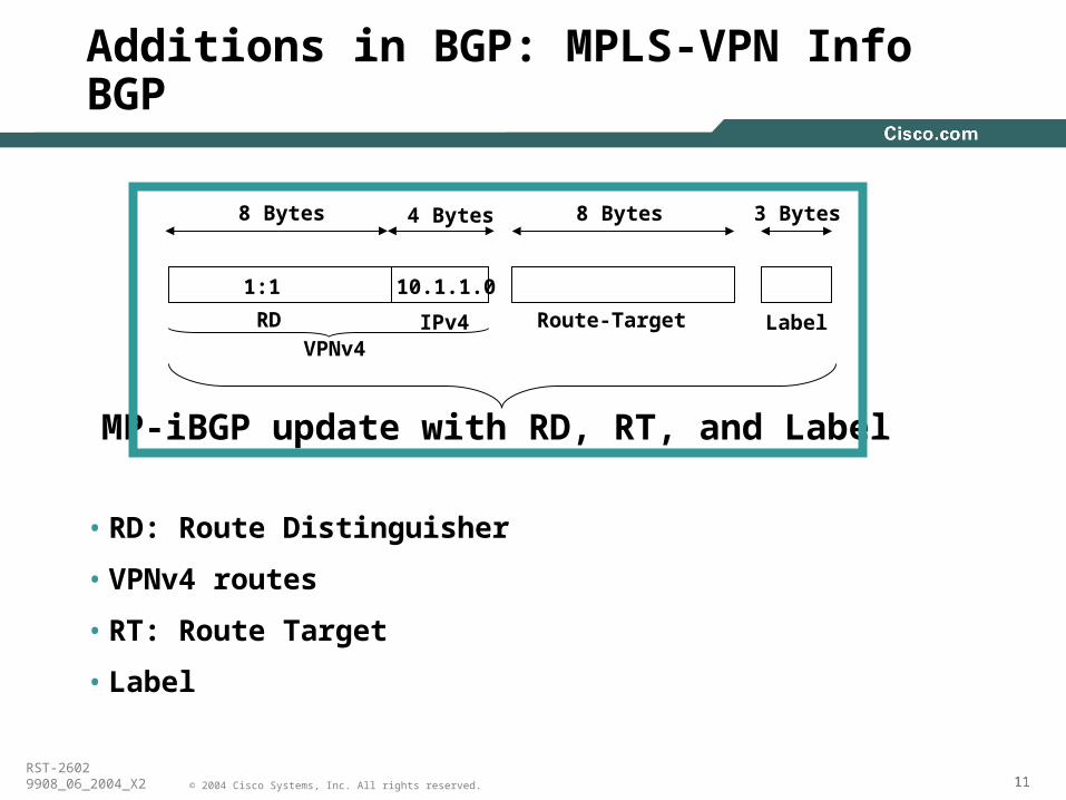
Additions in BGP: MPLS-VPN Info BGP
• RD: Route Distinguisher
• VPNv4 routes
• RT: Route Target
• Label
8 Bytes
Route-Target
3 Bytes
Label
MP-iBGP update with RD, RT, and Label
1:1
8 Bytes 4 Bytes
RD IPv4VPNv4
10.1.1.0

121212© 2004 Cisco Systems, Inc. All rights reserved.
RST-26029908_06_2004_X2
MPLS VPN Control Plane MP-BGP Update Components: VPNv4 address
• To convert an IPv4 address into a VPNv4 address, RD is appended to the IPv4 address i.e 1:1:10.1.1.0
• Makes the customer’s IPv4 route globally unique.
• Each VRF must be configured with an RD at the PE• RD is what that defines the VRF
8 Bytes
Route-Target
3 Bytes
Label
MP-IBGP update with RD, RT, and Label
1:1
8 Bytes 4 Bytes
RD IPv4VPNv4
10.1.1.0
!ip vrf v1 rd 1:1!
Cisco
Animation

131313© 2004 Cisco Systems, Inc. All rights reserved.
RST-26029908_06_2004_X2
MPLS VPN Control Plane MP-BGP Update Components: Route-Target
• Route-target (RT): Identifies the VRF for the received VPNv4 prefix. It is an 8-byte extended Community (a BGP attribute)
• Each VRF is configured with RT(s) at the PE
RT helps to color the prefix
8 Bytes
Route-Target
3 Bytes
Label
MP-IBGP update with RD, RT, and Label
1:1
8 Bytes 4 Bytes
RD IPv4VPNv4
10.1.1.0 2:2
!ip vrf v1 route-target import 1:1 route-target export 1:2!
Cisco
Animation

141414© 2004 Cisco Systems, Inc. All rights reserved.
RST-26029908_06_2004_X2
MPLS VPN Control Plane MP-BGP Update Components: Label
• The Label (for the VPNv4 prefix) is assigned only by the PE whose address is the Next-Hop attribute
PE routers re-write the Next-Hop with their own address (loopback)
“Next-Hop-Self” towards MP-iBGP neighbors by default
• PE addresses used as BGP Next-Hop must be uniquely known in the backbone IGP
DO NOT summarize the PE loopback addresses in the core
8 Bytes
Route-Target
3 Bytes
Label
MP-IBGP update with RD, RT, and Label
1:1
8 Bytes 4 Bytes
RD IPv4VPNv4
10.1.1.0 2:2 50
Cisco
Animation

151515© 2004 Cisco Systems, Inc. All rights reserved.
RST-26029908_06_2004_X2
MPLS VPN Control Plane: Putting It All Together
10.10.1.0/24
Next-Hop=CE-1
MP-iBGP update:RD:10.10.1.0
Next-hop=PE-1RT=Green, Label=100
1
3
10.1.1.0/24
PE1 PE2P
P P
P
CE2CE1
MPLS Backbone
Site 1 Site 2
1) PE1 receives an IPv4 update (eBGP,OSPF,EIGRP)
2) PE1 translates it into VPNv4 address• Assigns an RT per VRF configuration• Re-writes Next-Hop attribute to itself• Assigns a label based on VRF and/or interface
3) PE1 sends MP-iBGP UPDATE to other PE routers
Cisco
Animation

161616© 2004 Cisco Systems, Inc. All rights reserved.
RST-26029908_06_2004_X2
5
10.1.1.0/24
Next-Hop=CE-1
MP-iBGP update:RD:10.10.1.0
Next-hop=PE-1RT=Green, Label=100
1
3
10.1.1.0/24
PE1 PE2P
P P
P
CE2CE1
MPLS Backbone
Site 1 Site 2
10.1.1.0/24
Next-Hop=PE-2
4) PE2 receives and checks whether the RT=green is locally configured within any VRF, if yes, then
5) PE2 translates VPNv4 prefix back into IPv4 prefix,
• Installs the prefix into the VRF Routing table
• Updates the VRF CEF table with label=100 for 10.1.1.0/24
• Advertise this IPv4 prefix to CE2 (EBGP, OSPF, EIGRP)
MPLS VPN Control Plane: Putting It All Together
Cisco
Animation

171717© 2004 Cisco Systems, Inc. All rights reserved.
RST-26029908_06_2004_X2
10.1.1.0/24
PE1 PE2P2
P P
P1
CE2CE1
Site 1 Site 2
Global routing/forwarding tableDest->Next-HopPE2 P1, label: 50
Global routing/forwarding tableDest->NextHopPE1 P2, label: 25
VRF Green forwarding Table Dest->NextHop 10.1.1.0/24-PE1, label: 100
e
VRF Forwarding table (show ip cef vrf <vrf>)
•PE routers store VPN routes•Associated labels•Labels distributed through MP-BGP
The Global Forwarding table (show ip cef)
•PE routers store IGP routes•Associated labels•Label distributed through LDP/TDP
MPLS VPN Forwarding Plane:

181818© 2004 Cisco Systems, Inc. All rights reserved.
RST-26029908_06_2004_X2
PE2 imposes TWO labels for each packet going to the VPN destination 10.1.1.1
• The top label is LDP learned and Derived from an IGP route
Represents LSP to PE address (exit point of a VPN route)
• The second label is learned via MP-BGP
Corresponds to the VPN address
10.1.1.0/24
PE1 PE2
CE2CE1
Site 1 Site 2e
10.1.1.110.1.1.1
MPLS VPN Forwarding Plane:
P
P P
P
10.1.1.11002510.1.1.110050
10.1.1.1100
Cisco
Animation

191919© 2004 Cisco Systems, Inc. All rights reserved.
RST-26029908_06_2004_X2
Agenda
• MPLS VPN Definition?Technology
Configuration
• MPLS-VPN Services Providing load-shared traffic to the multihomed VPN sites
Providing Hub&Spoke service to the VPN customers
Providing MPLS VPN Extranet service
Providing Internet access service to VPN customers
Providing VRF-selection based services
Providing Remote Access MPLS VPN
Providing VRF-aware NAT services
• Advanced MPLS VPN TopicsInter-AS MPLS-VPN
CsC Carrier Supporting Carrier
• Best Practices
• Conclusion.

202020© 2004 Cisco Systems, Inc. All rights reserved.
RST-26029908_06_2004_X2
MPLS VPN Sample Configuration
ip vrf VPN-Ard 1:1route-target export 100:1route-target import 100:1
Interface Serial0ip address 192.168.10.1 255.255.255.0ip vrf forwarding VPN-A
VRF Definition
PE-P Configuration
P
PE1s1
Interface Serial1ip address 130.130.1.1 255.255.255.252mpls ip
router ospf 1network 130.130.1.0 0.0.0.3 area 0
10.1.1.0/24
PE1
CE1
Site 1
192.168.10.1
Se0
Se0
PE1
PE1
Cisco
Animation

212121© 2004 Cisco Systems, Inc. All rights reserved.
RST-26029908_06_2004_X2
MPLS VPN Sample Configuration
router bgp 1 neighbor 1.2.3.4 remote-as 1 neighbor 1.2.3.4 update-source loopback 0
address-family vpnv4 neighbor 1.2.3.4 activate neighbor 1.2.3.4 send-community both
PE: MP-IBGP
RR: MP-IBGP router bgp 1no bgp default route-target filterneighbor 1.2.3.6 remote-as 1neighbor 1.2.3.6 update-source loopback0
address-family vpnv4neighbor 1.2.3.6 route-reflector-clientNeighbor 1.2.3.6 activate
PE1 PE2
RR
PE1 PE2
RR
PE1
RR
Cisco
Animation

222222© 2004 Cisco Systems, Inc. All rights reserved.
RST-26029908_06_2004_X2
MPLS VPN Sample Configuration
router bgp 1!address-family ipv4 vrf VPN-A neighbor 192.168.10.2 remote-as 2 neighbor 192.168.10.2 activate exit-address-family!
PE-CE BGP
PE-CE OSPFrouter ospf 1!router ospf 2 vrf VPN-Anetwork 192.168.10.0 0.0.0.255 area 0!
10.1.1.0/24
PE1
CE1
Site 1
192.168.10.1
192.168.10.2
10.1.1.0/24
PE1
CE1
Site 1
192.168.10.1
192.168.10.2
PE1
PE1
Cisco
Animation

232323© 2004 Cisco Systems, Inc. All rights reserved.
RST-26029908_06_2004_X2
MPLS VPN Sample Configuration
router rip
address-family ipv4 vrf VPN-A version 2 no auto-summary network 192.168.10.0 exit-address-family
PE-CE RIP
PE-CE EIGRProuter eigrp 1
address-family ipv4 vrf VPN-A network 192.168.10.0 0.0.0.255 autonomous-system 1 exit-address-family
10.1.1.0/24
PE1
CE1
Site 1
192.168.10.1
192.168.10.2
10.1.1.0/24
PE1
CE1
Site 1
192.168.10.1
192.168.10.2
Cisco
Animation

242424© 2004 Cisco Systems, Inc. All rights reserved.
RST-26029908_06_2004_X2
MPLS VPN Sample Configuration
ip route vrf VPN-A 10.1.1.0 255.255.255.0 192.168.10.2
PE-CE Static
PE-CE MB-iBGP routes to VPNrouter rip address-family ipv4 vrf VPN-A version 2 redistribute bgp 1 metric 1 no auto-summary network 192.168.10.0 exit-address-family
10.1.1.0/24
PE1
CE1
Site 1
192.168.10.1
192.168.10.2
If PE-CE protocol is non BGP then redistribution of other sites VPN routes from MP-IBGP is required.
PE1
RR
CE1
Site 1
Cisco
Animation

252525© 2004 Cisco Systems, Inc. All rights reserved.
RST-26029908_06_2004_X2
MPLS VPN Sample Configuration
router bgp 1 neighbor 1.2.3.4 remote-as 1 neighbor 1.2.3.4 update-source loopback 0
address-family ipv4 vrf VPN-A redistribute {rip|connected|static|eigrp|ospf}
PE-RR (VPN routes to VPNv4)
PE1
RR
CE1
Site 1
If PE-CE protocol is non BGP then redistribution of other sites VPN routes into MP-IBGP is required.
Cisco
Animation

262626© 2004 Cisco Systems, Inc. All rights reserved.
RST-26029908_06_2004_X2
Agenda
• MPLS VPN Definition?Technology
Configuration
• MPLS-VPN Services Providing load-shared traffic to the multihomed VPN sites
Providing Hub&Spoke service to the VPN customers
Providing MPLS VPN Extranet service
Providing Internet access service to VPN customers
Providing VRF-selection based services
Providing Remote Access MPLS VPN
Providing VRF-aware NAT services
• Advanced MPLS VPN TopicsInter-AS MPLS-VPN
CsC Carrier Supporting Carrier
• Best Practices
• Conclusion.

272727© 2004 Cisco Systems, Inc. All rights reserved.
RST-26029908_06_2004_X2
MPLS VPN Services:1. Loadsharing for the VPN traffic
• VPN sites (such as Site A) could be multihomed
• VPN customer may demand the traffic to the multihomed sites be loadshared
PE11
PE2
MPLS Backbone
PE12
CE1
Site A
171.68.2.0/24
Site B
CE2
RR
Route Advertisement

282828© 2004 Cisco Systems, Inc. All rights reserved.
RST-26029908_06_2004_X2
MPLS VPN Services:1. Loadsharing for the VPN traffic: Cases
PE11
PE2
MPLS Backbone
PE12
CE1
Site A
171.68.2.0/24
Site B
CE2
RR
Traffic Flow
RR
PE11
PE2
MPLS Backbone
PE12
CE1
Site A
171.68.2.0/24
Site B
CE2
CE2
Traffic Flow
1 CE 2 PEs
2 CEs 2 PEs

292929© 2004 Cisco Systems, Inc. All rights reserved.
RST-26029908_06_2004_X2
MPLS VPN Services:1. Loadsharing for the VPN Traffic: Deployment
How to deploy the loadsharing ?
1. Configure different VRFs i.e RDs for multihomed site/interfaces.
2. Enable BGP multipath within the relevant BGP VRF address-family at Remote/Receiving PE2.
PE11
PE2
MPLS BackbonePE12
CE1
Site A
171.68.2.0/24
Site B
CE2
RRip vrf greenrd 300:11route-target both 1:1
ip vrf greenrd 300:12route-target both 1:1
router bgp 1address-family ipv4 vrf greenmaximum-paths eibgp 2
1
1
2
ip vrf greenrd 300:13route-target both 1:1
1
Cisco
Animation

303030© 2004 Cisco Systems, Inc. All rights reserved.
RST-26029908_06_2004_X2
MPLS VPN Services:1. Loadsharing for the VPN Traffic(实验)
• RR must advertise all the paths learned via PE11 and PE12 to the remote PE routers
With different RD per VRF, RR does the Best path calculation per RD and advertise them to remote PE
• Watch out for the increased (~20%) memory consumption (within BGP) due to multipaths at the PEs
• “eiBGP multipath” implicitly provides eBGP and iBGP multipath for VPN paths
PE11
PE2
MPLS Backbone
PE12
CE1
Site A
171.68.2.0/24
Site B
CE2
RRRoute Advertisement

313131© 2004 Cisco Systems, Inc. All rights reserved.
RST-26029908_06_2004_X2
MPLS-VPN Services: 2. Hub & Spoke Service to the VPN Customers
• Traditionally, VPN deployments are Hub&Spoke.
Spoke to spoke communication is via Hub site only.
• Despite MPLS VPN’s implicit any-to-any i.e full-mesh connectivity, Hub&Spoke service can easily be offered.
Done with import and export of Route-Target (RT).

323232© 2004 Cisco Systems, Inc. All rights reserved.
RST-26029908_06_2004_X2
MPLS-VPN Services: 2. Hub & Spoke Service - Configuration
PE-SA
PE-Hub
MPLS VPN Backbone
PE-SB
CE-SA
CE-SBSpoke B
Spoke A
171.68.1.0/24
171.68.2.0/24
Eth0/0.2
Eth0/0.1
ip vrf green-spoke1description VRF for SPOKE Ard 300:111route-target export 1:1route-target import 2:2
ip vrf green-spoke2description VRF for SPOKE Brd 300:112route-target export 1:1route-target import 2:2
ip vrf HUB-OUTdescription VRF for traffic from HUBrd 300:11route-target import 1:1
ip vrf HUB-INdescription VRF for traffic to HUB rd 300:12route-target export 2:2
Cisco
Animation

333333© 2004 Cisco Systems, Inc. All rights reserved.
RST-26029908_06_2004_X2
MPLS-VPN Services: 2. Hub & Spoke Service – Control Plane
PE-SA
MPLS Backbone
PE-SB
CE-SA
CE-SB
Spoke B
Spoke A
VRF HUB-IN
VRF HUB-OUT
VRF HUB-OUT RT and LFIBDestination NextHop Label171.68.1.0/24 PE-SA 40171.68.2.0/24 PE-SB 50
171.68.1.0/24
171.68.2.0/24
• All traffic between spokes must pass through the Hub/Central Site.Hub Site could offer FireWall, NAT like applications.
• Two VRF solution at the PE-Hub: • VRF HUB_OUT would have knowledge of every spoke routes.• VRF HUB_IN only have Default Route and advertise that to Spoke PEs.
• Import and export Route-Target within a VRF must be different.
PE-Hub
VRF HUB-IN Routing TableDestination NextHop0.0.0.0 CE-H1
Adv 0.0.0.0Label 35Route-Target 2:2
Adv 171.68.2.0/24Label 50Route-Target 1:1
Adv 171.68.1.0/24Label 40 Route-Target 1:1
VRF RT and LFIB at PE-SA0.0.0.0 PE-Hub 35171.68.1.0/24 CE-SA
VRF RT and LFIB at PE-SB0.0.0.0 PE-Hub 35171.68.2.0/24 CE-SB
Cisco
Animation

343434© 2004 Cisco Systems, Inc. All rights reserved.
RST-26029908_06_2004_X2
PE-SA
PE-Hub
MPLS Backbone
PE-SB
CE-SA
CE-SBSpoke B
Spoke A
VRF HUB-IN
VRF HUB-OUT
171.68.1.0/24
171.68.2.0/24
171.68.1.1
LH 35 171.68.1.1
LA 40 171.68.1.1
171.68.1.1
MPLS-VPN Services(实验内容 ): 2. Hub & Spoke Service – Forwarding Plane
Cisco
Animation

353535© 2004 Cisco Systems, Inc. All rights reserved.
RST-26029908_06_2004_X2
MPLS-VPN Services3. Extranet VPN
• MPLS VPN, by default, isolates one VPN customer from another.
Separate Virtual Routing Table for each VPN customer
• Communication between VPNs may be required i.e. Extranet.
External Inter-company communication (dealers with manufacturer, Retailer with wholesale provider etc)
Management VPN, Shared-service VPN etc.
• Needs right import and export route-target (RT) values configuration within the VRFs
export-map or import-map should be used

363636© 2004 Cisco Systems, Inc. All rights reserved.
RST-26029908_06_2004_X2
3. MPLS-VPN Services: Extranet VPNGoal: Only VPN_A site#1 to be reachable to VPN_B
171.68.0.0/16 PE1 PE2
MPLS Backbone
VPN_A Site#2
soP
VPN_A Site#1
VPN_B Site#1
180.1.0.0/16
ip vrf VPN_Ard 3000:111export map VPN_A_Export import map VPN_A_Importroute-target import 3000:111route-target export 3000:111route-target import 3000:1! route-map VPN_A_Export permit 10 match ip address 1 set extcommunity rt 3000:2!route-map VPN_A_Import permit 10 match ip address 2! access-list 1 permit 171.68.0.0 0.0.0.0access-list 2 permit 180.1.0.0 0.0.0.0
ip vrf VPN_Brd 3000:222export map VPN_B_Export import map VPN_B_Importroute-target import 3000:222route-target export 3000:222route-target import 3000:2! route-map VPN_B_Export permit 10 match ip address 2 set extcommunity rt 3000:1!route-map VPN_B_Import permit 10 match ip address 1! access-list 1 permit 171.68.0.0 0.0.0.0access-list 2 permit 180.1.0.0 0.0.0.0
192.6.0.0/16
Only Site#1 of both VPNs will communicate to each other, Site#2 won’t.
Cisco
Animation
373737© 2004 Cisco Systems, Inc. All rights reserved.
RST-26029908_06_2004_X2
MPLS-VPN Services4. Internet Access Service to VPN Customers
• Could be provided as another value-added service.
• Security mechanism must be in place at both provider network and customer network
To protect from the Internet vulnerabilities
• VPN customers benefit from the single point of contact for both Intranet and Internet connectivity

383838© 2004 Cisco Systems, Inc. All rights reserved.
RST-26029908_06_2004_X2
MPLS-VPN Services4. Internet Access: Different Methods of Service
• Four ways to provide the Internet service
1. VRF Specific default route with “global” keyword
2. Separate PE-CE sub-interface (nonVRF)
3. Extranet with Internet-VRF
4. VRF-aware NAT

393939© 2004 Cisco Systems, Inc. All rights reserved.
RST-26029908_06_2004_X2
MPLS-VPN Services(实验内容)4. Internet Access: Different Methods of Service
1. VRF Specific default route
1.1 Static default route to move traffic from VRF to Internet (global routing table)
1.2 Static routes for VPN customers to move traffic from Internet (global routing table) to VRF
2. Separate PE-CE sub-interface (non VRF)
May run BGP to propagate Internet routes between PE and CE
3. Extranet with Internet-VRF
VPN packets never leave VRF context ; issue with Overlapping VPN address
4. Extranet with Internet-VRF along with VRF-aware NAT
VPN packets never leave VRF context; works well with overlapping VPN address
404040© 2004 Cisco Systems, Inc. All rights reserved.
RST-26029908_06_2004_X2
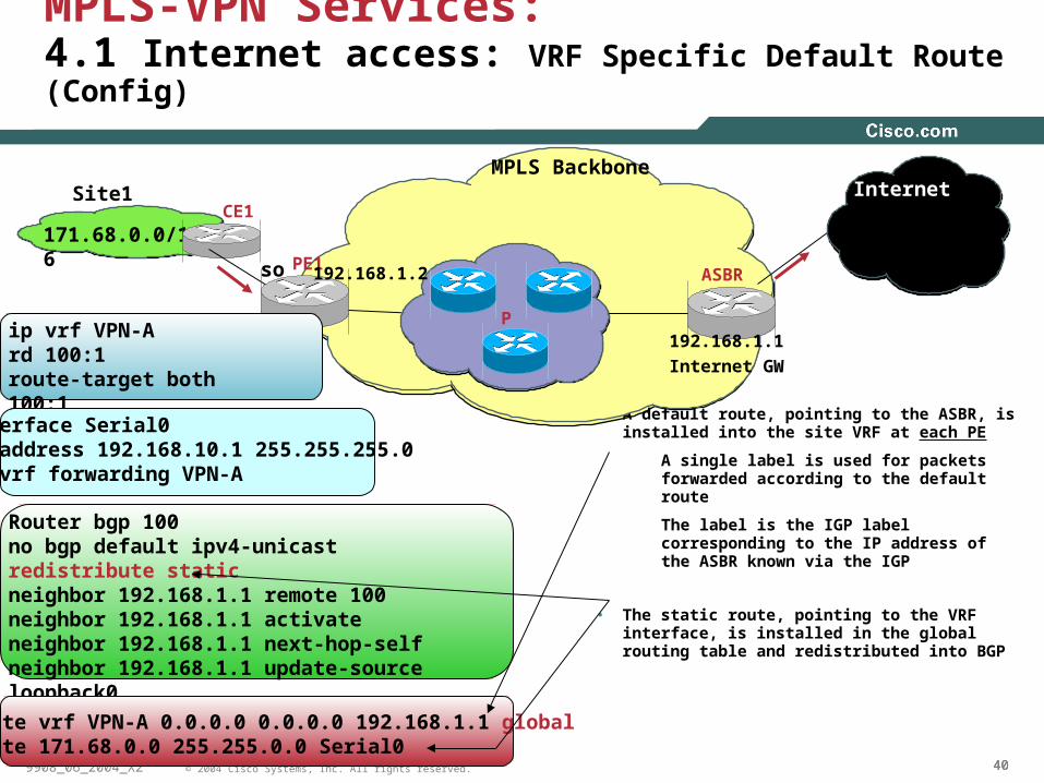
• A default route, pointing to the ASBR, is installed into the site VRF at each PE
A single label is used for packets forwarded according to the default route
The label is the IGP label corresponding to the IP address of the ASBR known via the IGP
• The static route, pointing to the VRF interface, is installed in the global routing table and redistributed into BGP
171.68.0.0/16PE1
ASBR
CE1
MPLS Backbone
192.168.1.1
Internet GW
so
Pip vrf VPN-Ard 100:1route-target both 100:1Interface Serial0ip address 192.168.10.1 255.255.255.0ip vrf forwarding VPN-A
Router bgp 100no bgp default ipv4-unicastredistribute staticneighbor 192.168.1.1 remote 100neighbor 192.168.1.1 activateneighbor 192.168.1.1 next-hop-selfneighbor 192.168.1.1 update-source loopback0
ip route vrf VPN-A 0.0.0.0 0.0.0.0 192.168.1.1 globalip route 171.68.0.0 255.255.0.0 Serial0
Site1
192.168.1.2
MPLS-VPN Services: 4.1 Internet access: VRF Specific Default Route (Config)
Internet
Cisco
Animation

414141© 2004 Cisco Systems, Inc. All rights reserved.
RST-26029908_06_2004_X2
171.68.0.0/16
PE1 PE2
MPLS Backbone
192.168.1.1
so
P
VRF Routing/FIB Table
Destination Label/interface
0.0.0.0/0 192.168.1.1 (global)
Site-1 Serial 0
Global Routing/FIB Table
Destination Label/Interface
192.168.1.1/32 Label=30
171.68.0.0/16 Serial 0
IP packetD=Cisco.com
Label = 30 IP packetD=Cisco.com
IP packetD=Cisco.com
IP packetD=171.68.1.1
Label = 35
IP packetD=171.68.1.1
Global Table and LFIB
Destination Label/Interface
192.168.1.2/32 Label=35
171.68.0.0/16 192.168.1.2
Internet Serial 0
192.168.1.2
IP packetD=171.68.1.1
Pros
Different Internet gatewayscan be used for different VRFs
PE routers need not to hold the Internet table
Simple Configuration
Cons
Using default route for Internetrouting does NOT allow any otherdefault route for intrA_VPN routing
Increasing size of global routing Table by leaking VPN routes.
Static configuration
Site1
so
MPLS-VPN Services: 4.1 Internet access: VRF Specific Default Route (Forwarding)
Internet
Cisco
Animation

424242© 2004 Cisco Systems, Inc. All rights reserved.
RST-26029908_06_2004_X2
MPLS-VPN Services4.2 Internet Access
1. VRF Specific default route
1.1 Static default route to move traffic from VRF to Internet (global routing table)
1.2 Static routes for VPN customers to move traffic from Internet (global routing table) to VRF
2. Separate PE-CE sub-interface (non VRF)
May run BGP to propagate Internet routes between PE and CE
3. Extranet with Internet-VRF
VPN packets never leave VRF context ; Overlapping VPN addresses could be a problem
4. Extranet with Internet-VRF alongwith VRF-aware NAT
VPN packets never leave VRF context; works well with overlapping VPN addresses

434343© 2004 Cisco Systems, Inc. All rights reserved.
RST-26029908_06_2004_X2
ip vrf VPN-Ard 100:1route-target both 100:1Interface Serial0.1 ip vrf forwarding VPN-A ip address 192.168.20.1 255.255.255.0 frame-relay interface-dlci 100!Interface Serial0.2 ip address 171.68.10.1 255.255.255.0 frame-relay interface-dlci 200!
Router bgp 100no bgp default ipv4-unicast[snip]…neighbor 171.68.10.2 remote 502
4.2 Internet Access Service to VPN CustomersUsing Separate Sub-Interface (Config)
171.68.0.0/16
PE1 ASBR
CE1 MPLS Backbone
Internet GW
192.168.1.1S0.2
P
BGP-4
Site1
192.168.1.2
S0.1
One sub-interface for VPN routing associated to a VRF
Another sub-interface for Internet routing associated to the global routing table.
Could advertise full Internet Routes or a default route to CE.
The PE will need to advertise VPN routes to the Internet (via global routing table)
Internet Internet

444444© 2004 Cisco Systems, Inc. All rights reserved.
RST-26029908_06_2004_X2
171.68.0.0/16
PE1 PE2
MPLS Backbone
PE-Internet GW
192.168.1.1S0.2
P
Site1
192.168.1.2
S0.1
IP packetD=Cisco.com
CE routing tableVPN routes Serial0.1Internet routes Serial0.2
PE Global Table and FIBInternet routes 192.168.1.1192.168.1.1 Label=30
Label = 30 IP packetD=Cisco.com IP packet
D=cisco.com
Pros
CE could dual home and perform optimal routing.
Traffic separation done by CE.
Cons
PE to hold full Internet routes.
BGP complexities introduced in CE.
Internet Access Service to VPN Customers4.2 Using Separate Sub-Interface (Forwarding)
Internet
Cisco
Animation
454545© 2004 Cisco Systems, Inc. All rights reserved.
RST-26029908_06_2004_X2
Internet Access Service4.3 Extranet with Internet-VRF
• The internet routes could be placed within the VRF at the Internet-GW i.e. ASBR
• VRFs for customers could ‘extranet’ with the internet VRF and receive either default, partial or full internet routes
• Be careful if duplicating the internet routes in each VRF
• Works well when the VPN customers don’t have overlapping addresses

464646© 2004 Cisco Systems, Inc. All rights reserved.
RST-26029908_06_2004_X2
Internet Access Service4.4 Internet Access using VRF-aware NAT
• If the VPN customers need Internet access without internet routes, then VRF-aware NAT can be used at the Internet-GW i.e. ASBR
• The Internet GW doesn’t need to have internet routes either
• Overlapping VPN addresses is not a problem
• More in the “VRF-aware NAT” slides,…..

474747© 2004 Cisco Systems, Inc. All rights reserved.
RST-26029908_06_2004_X2
MPLS VPN Service5. VRF-Selection
• The common notion is that the VRF must be associated to an interface
• “VRF-selection” breaks this association and associate multiple VRFs to an interface
• Each packet on the PE-CE interface could be handled (based on certain criteria) via different VRF routing tables
Criteria such as source/dest IP address, ToS, TCP port etc. specified via route-map
• Voice and Data can be separated out into different VRFs at the PE

484848© 2004 Cisco Systems, Inc. All rights reserved.
RST-26029908_06_2004_X2
MPLS VPN Service5. VRF-Selection – Based on Source IP Address
PE1PE2
MPLS Backbone(Cable Company)CE1
RR
44.3.12.1
66.3.0.0/16
VPN Green
44.3.0.0/16
VPN Blue
33.3.0.0/16
VPN Brown
66.3.1.25
33.3.14.1
Global Interface
Se0/0
CableSetup
VRF Interfaces
Traffic Flows
ip vrf brown rd 3000:111 route-target export 3000:1 route-target import 3000:1!ip vrf blue rd 3000:222 route-target export 3000:2 route-target import 3000:2!ip vrf green rd 3000:333 route-target export 3000:3 route-target import 3000:3
route-map PBR-VRF-Selection permit 10 match ip address 40 set vrf brown
route-map PBR-VRF-Selection permit 20 match ip address 50 set vrf blue
route-map PBR-VRF-Selection permit 30 match ip address 60 set vrf green
interface Serial0/0 ip address 215.2.0.6 255.255.255.252 ip policy route-map PBR-VRF-Selection ip receive brown ip receive blue ip receive green
access-list 40 permit 33.3.0.0 0.0.255.255access-list 50 permit 44.3.0.0 0.0.255.255access-list 60 permit 66.3.0.0 0.0.255.255
Cisco
Animation

494949© 2004 Cisco Systems, Inc. All rights reserved.
RST-26029908_06_2004_X2
MPLS VPN Service6. Remote Access Service
• Remote access users i.e. dial users, IPSec users could directly be terminated in VRF
PPP users can be terminated into VRFs
IPSec tunnels can be terminated into VRFs
• Remote Access services integration with MPLS VPN opens up new opportunities for Providers

505050© 2004 Cisco Systems, Inc. All rights reserved.
RST-26029908_06_2004_X2
Internet
MPLS VPN Service6. Remote Access Service– IPSec to MPLS VPN
Internet
Corporate IntranetCorporate IntranetBranchBranchOfficeOffice AccessAccess
Remote Users/ Telecommuters
MPLS VPNIPSec SessionIP IP
Cable/DSL/ISDN ISP
IP/MPLS/Layer 2Based Network
VPN A
VPN B
SP Shared NetworkSP Shared Network
Customer B
Customer Ahead office
Customer C
PEPE
PEPE
VPN C
SOHO
Local or Direct Dial ISP
Cisco IOS VPN Routers or Cisco Client 3.x or higher Customer A
branch office
PEPE
SP AAA Customer AAAPE+IPSec
Aggregator
VPN A
Cisco
Animation

515151© 2004 Cisco Systems, Inc. All rights reserved.
RST-26029908_06_2004_X2
MPLS-VPN Services7. VRF-Aware NAT Services
• VPN customers could be using ‘overlapping’ IP address i.e. 10.0.0.0/8
• Such VPN customers must NAT their traffic before using either “extranet” or “internet” or any shared* services
• PE is capable of NATting the VPN packets (eliminating the need for an extra NAT device)
* VoIP, Hosted Content, Management etc/

525252© 2004 Cisco Systems, Inc. All rights reserved.
RST-26029908_06_2004_X2
MPLS-VPN Services7. VRF-Aware NAT Services
• Typically, inside interface(s) connect to private address space and outside interface connect to global address space
NAT occurs after routing for traffic from inside-to-outside interfaces
NAT occurs before routing for traffic from outside-to-inside interfaces
• Each NAT entry is associated with the VRF
• Works on VPN packets in the following switch paths : IP->IP, IP->MPLS and MPLS->IP

535353© 2004 Cisco Systems, Inc. All rights reserved.
RST-26029908_06_2004_X2
Internet
MPLS-VPN Services:7. VRF-Aware NAT Services – Internet Access
PE11
PE-ASBR
MPLS Backbone
PE12
CE1
Blue VPN Site
10.1.1.0/24
P
CE2
10.1.1.0/24
Green VPN Site
ip nat inside
ip nat outside
217.34.42.2.1
VRF-aware NAT Specific ConfigVRF specific Config
ip nat pool pool-green 24.1.1.0 24.1.1.254 prefix-length 24
ip nat pool pool-blue 25.1.1.0 25.1.1.254 prefix-length 24
ip nat inside source list vpn-to-nat pool pool-green vrf greenip nat inside source list vpn-to-nat pool pool-blue vrf blue
ip access-list standard vpn-to-nat permit 10.1.1.0 0.0.0.255
ip route vrf green 0.0.0.0 0.0.0.0 217.34.42.2 globalip route vrf blue 0.0.0.0 0.0.0.0 217.34.42.2 global
ip vrf green rd 3000:111 route-target both 3000:1ip vrf blue rd 3000:222 route-target both 3000:2
router bgp 3000 address-family ipv4 vrf green network 0.0.0.0 address-family ipv4 vrf blue network 0.0.0.0
Cisco
Animation

545454© 2004 Cisco Systems, Inc. All rights reserved.
RST-26029908_06_2004_X2
MPLS-VPN Services:7. VRF-Aware NAT Services – Internet Access
• This is also one of the ways to provide Internet access to VPN customers with or without overlapping addresses
PE11 PE-ASBR
MPLS Backbone
PE12
CE1
Blue VPN Site
10.1.1.0/24
P
CE2
Traffic Flows
10.1.1.0/24
Green VPN Site
Src=10.1.1.1 Dest=Internet
Src=24.1.1.1 Dest=Internet
Src=25.1.1.1 Dest=Internet
Src=10.1.1.1 Dest=Internet
Label=30 Src=10.1.1.1 Dest=Internet
Label=40 Src=10.1.1.1 Dest=Internet
IP Packet
MPLS Packet
IP Packet
NAT TableVRF IP Source Global IP VRF-table-id10.1.1.1 24.1.1.1 green10.1.1.1 25.1.1.1 blue
•PE-ASBR removes the label from the received MPLS packets per LFIB
•Performs NAT on the resulting IP packets
•Forwards the packet
Internet
Cisco
Animation

555555© 2004 Cisco Systems, Inc. All rights reserved.
RST-26029908_06_2004_X2
Agenda
• MPLS VPN Definition?Technology
Configuration
• MPLS-VPN Services Providing load-shared traffic to the multihomed VPN sites
Providing Hub&Spoke service to the VPN customers
Providing MPLS VPN Extranet service
Providing Internet access service to VPN customers
Providing VRF-selection based services
Providing Remote Access MPLS VPN
Providing VRF-aware NAT services
• Advanced MPLS VPN TopicsInter-AS MPLS-VPN
CsC Carrier Supporting Carrier
• Best Practices
• Conclusion.

565656© 2004 Cisco Systems, Inc. All rights reserved.
RST-26029908_06_2004_X2
What Is Inter-AS?
VPN-AVPN-A
PE-1
PE2
CE2 CE-1
AS #1AS #2
149.27.2.0/24
MP-iBGP update::MP-iBGP update::
BGP, OSPF, RIPv2 149.27.2.0/24,NH=CE-1
BGP, OSPF, RIPv2 149.27.2.0/24,NH=CE-1
Problem:
How do Provider X and Provider Y exchange VPN
routes ?
???ASBR1 ASBR2
RR2RR1
Provider X Provider Y
Cisco
Animation

575757© 2004 Cisco Systems, Inc. All rights reserved.
RST-26029908_06_2004_X2
Inter-AS Deployment Scenarios
VPN-A
PE1
VPN-A
PE2
CE2
1. Back-to-back VRFs
2. MP-eBGP for VPNv4
3. Multihop MP-eBGP between RRs
4. Non-VPN Transit Provider
Following options/Scenarios for deploying Inter-AS :Following options/Scenarios for deploying Inter-AS :
AS #1 AS #2
ASBR1 ASBR2
CE1
•2 and 3 are more common and will be discussed. 1 and 4 are in backup slides.
Cisco
Animation

585858© 2004 Cisco Systems, Inc. All rights reserved.
RST-26029908_06_2004_X2
Scenario 2: MP-eBGP between ASBRs to Exchange VPNv4 Routes
• New CLI “no bgp default route-target filter” is needed on the ASBRs.
• ASBRs exchange VPN routes using eBGP (VPNv4 af)
• ASBRs store all VPN routes –
But only in BGP table and LFIB table
Not in routing nor in CEF table
• ASBRs don’t need -
VRFs to be configured on them
LDP between them

595959© 2004 Cisco Systems, Inc. All rights reserved.
RST-26029908_06_2004_X2
Scenario 2: MP-eBGP bet ASBRs for VPNv4Control Plane (实验内容)
PE-1 PE-2
VPN-B
CE-2 CE-3
VPN-B
ASBR-1 ASBR-2
10.1.1.0/24
BGP, OSPF, RIPv2 10.1.1.0/24, NH=CE-2BGP, OSPF, RIPv2
10.1.1.0/24, NH=CE-2
MP-iBGP update:RD:1:27:10.1.1.0/24, NH=PE-1RT=1:1, Label=(40)
MP-iBGP update:RD:1:27:10.1.1.0/24, NH=PE-1RT=1:1, Label=(40)
MP-iBGP update:RD:1:27:10.1.1.0/24, NH=ASBR-2RT=1:1, Label=(30)
MP-iBGP update:RD:1:27:10.1.1.0/24, NH=ASBR-2RT=1:1, Label=(30)
BGP, OSPF, RIPv2 10.1.1.0/24, NH=PE-2 BGP, OSPF, RIPv2
10.1.1.0/24, NH=PE-2
MP-eBGP update:RD:1:27:10.1.1.0/24, NH=ASBR-1RT=1:1, Label=(20)
MP-eBGP update:RD:1:27:10.1.1.0/24, NH=ASBR-1RT=1:1, Label=(20)
Cisco
Animation

606060© 2004 Cisco Systems, Inc. All rights reserved.
RST-26029908_06_2004_X2
Scenario 2: MP-eBGP bet ASBRs for VPNv4Forwarding Plane
PE-1PE-2
VPN-BCE-2 CE-3
VPN-B
ASBR-1 ASBR-2
10.1.1.0/24
10.1.1.1
10.1.1.130
20 10.1.1.110.1.1.140
10.1.1.1
10.1.1.13020
10.1.1.14030
P1
P2
MPLS Packets between ASBRsMPLS Packets
between ASBRs
•More scalable.Only one interface between ASBRs routersNo VRF configuration on ASBR.Less memory consumption (no RIB/FIB memory)
•MPLS label switching between providersStill simple, more scalable & works today
Pros Cons•Automatic Route Filtering must be disabled
But we can apply BGP filtering.
•ASBRs are still required to hold VPN routes
Cisco
Animation

616161© 2004 Cisco Systems, Inc. All rights reserved.
RST-26029908_06_2004_X2
Cisco IOS Configuration Scenario 2: External MP-BGP between ASBRs for VPNv4(实验内容)
VPN-A
PE1
VPN-A
PE2
CE-2CE-1
ASBR1 ASBR2
AS #1 AS #2
MP-eBGP for VPNv4
Label exchange between ASBRs using
MP-eBGP
1.1.1.0/30
Note: ASBR must already have MP-iBGP session with iBGP neighbors such as RRs or PEs.
Router bgp xno bgp default route-target filterneighbor 1.1.1.x remote-as x!address-family vpnv4neighbor 1.1.1.x activateneighbor 1.1.1.x send-com extended
ASBR MB-EBGP Configuration
Cisco
Animation
626262© 2004 Cisco Systems, Inc. All rights reserved.
RST-26029908_06_2004_X2
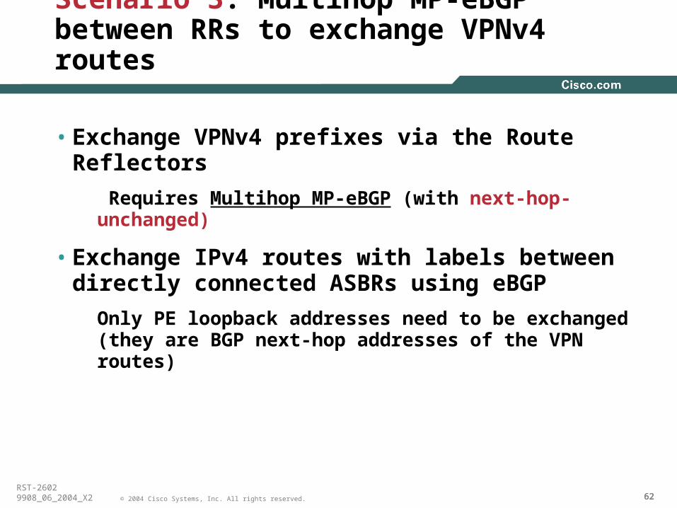
Scenario 3: Multihop MP-eBGP between RRs to exchange VPNv4 routes
• Exchange VPNv4 prefixes via the Route Reflectors
Requires Multihop MP-eBGP (with next-hop-unchanged)
• Exchange IPv4 routes with labels between directly connected ASBRs using eBGP
Only PE loopback addresses need to be exchanged (they are BGP next-hop addresses of the VPN routes)

636363© 2004 Cisco Systems, Inc. All rights reserved.
RST-26029908_06_2004_X2
Scenario 3: Multihop MP-eBGP between RRs for VPN routes : Control Plane
PE-1 PE-2
VPN-B
CE-2
CE-3
VPN-B
ASBR-1
RR-2
AS#2ASBR-2
RR-1
IP-v4 update: Network=PE-1 NH=ASBR-1Label=(20)
IP-v4 update: Network=PE-1 NH=ASBR-1Label=(20)
BGP, OSPF, RIPv2 10.1.1.0/24,NH=CE-2BGP, OSPF, RIPv2 10.1.1.0/24,NH=CE-2
10.1.1.0/24
VPN-v4 update:RD:1:27:10.1.1.0/24, NH=PE-1RT=1:1, Label=(90)
VPN-v4 update:RD:1:27:10.1.1.0/24, NH=PE-1RT=1:1, Label=(90)
VPN-v4 update:RD:1:27:10.1.1.0/24, NH=PE-1RT=1:1, Label=(90)
VPN-v4 update:RD:1:27:10.1.1.0/24, NH=PE-1RT=1:1, Label=(90)
VPN-v4 update:RD:1:27:10.1.1.0/24, NH=PE-1RT=1:1, Label=(90)
VPN-v4 update:RD:1:27:10.1.1.0/24, NH=PE-1RT=1:1, Label=(90)
BGP, OSPF, RIPv2 10.1.1.0/24,NH=PE-2BGP, OSPF, RIPv2 10.1.1.0/24,NH=PE-2
AS#1
IGP+LDP: Network=PE-1 NH=ASBR-2Label=(30)
IGP+LDP: Network=PE-1 NH=ASBR-2Label=(30)
IGP+LDP: Network=PE-1 NH=PE-1Label=(40)
IGP+LDP: Network=PE-1 NH=PE-1Label=(40)
Note - Instead of IGP+Label, iBGP+Label can be used to exchange PE routes/label. Please see Scenario#5 on slide#49 and 50.
Cisco
Animation

646464© 2004 Cisco Systems, Inc. All rights reserved.
RST-26029908_06_2004_X2
Scenario 3: Multihop MP-eBGP between RRs for VPN routes : Forwarding Plane
PE-1
PE-2
VPN-B
CE-2 CE-3
VPN-B
RR-2
ASBR-2
RR-1
10.1.1.0/24
10.1.1.1
90 10.1.1.130
20 90 10.1.1.1
10.1.1.190
10.1.1.1
50 90 10.1.1.1
40 90 10.1.1.1
ASBR-1
P1 P2
Note - Instead of IGP+Label, iBGP+Label can be used to exchange PE routes/label.
Cisco
Animation

656565© 2004 Cisco Systems, Inc. All rights reserved.
RST-26029908_06_2004_X2
Scenario 3: Pros/Cons
Pros Cons•More scalable than Scenario 1 and 2.
Separation of control and forwarding planes
•Route Reflector exchange VPNv4 routes+labels RR hold the VPNv4 information anyway
•ASBRs now exchange only IPv4 routes+labelsASBR Forwards MPLS packets
•Advertising PE addresses to another AS may not be acceptable to few providers.

666666© 2004 Cisco Systems, Inc. All rights reserved.
RST-26029908_06_2004_X2
Cisco IOS Configuration Scenario 3: Multihop MP-eBGP between RRs for VPNv4(实验)
VPN-A
PE1
VPN-A
PE2
CE-2
CE-1
ASBR-1
RR-2
AS #1 AS #2
Multihop MP-eBGP for VPNv4 with
next-hop-unchange
ASBR-2
RR-1
eBGP IPv4 + Labels
iBGPipv4+label could also be used in within each AS (instead of “network <x.x.x.x>”) to propagate the label information for PEs.
router ospf xredistribute bgp 1 subnets!router bgp xneighbor < ASBR-x > remote-as x!address-family ipv4Network <PEx> mask 255.255.255.255Network <RRx> mask 255.255.255.255neighbor < ASBR-x > activateneighbor < ASBR-x > send-label
router bgp xneighbor <RR-x> remote-as xneighbor <RR-x> ebgp-multihopneighbor <RR-x> update loopback 0!address-family vpnv4neighbor <RR-x> activateneighbor <RR-x> send-com extendedneighbor <RR-x> next-hop-unchanged
RR Configuration ASBR Configuration
Cisco
Animation

676767© 2004 Cisco Systems, Inc. All rights reserved.
RST-26029908_06_2004_X2
Inter-AS Deployment Guidelines
1. Use ASN in the Route-target i.e. ASN:xxxx
2. Max-prefix limit (both BGP and VRF) on PEs
3. Security (BGP MD5, BGP filtering, BGP max-prefix etc) on ASBRs
4. End-to-end QoS agreement on ASBRs
5. Route-Target rewrite on ASBR
6. Internet connectivity on the same ASBR ??

686868© 2004 Cisco Systems, Inc. All rights reserved.
RST-26029908_06_2004_X2
Agenda
• MPLS VPN Definition?Technology
Configuration
• MPLS-VPN Services Providing load-shared traffic to the multihomed VPN sites
Providing Hub&Spoke service to the VPN customers
Providing MPLS VPN Extranet service
Providing Internet access service to VPN customers
Providing VRF-selection based services
Providing Remote Access MPLS VPN
Providing VRF-aware NAT services
• Advanced MPLS VPN TopicsInter-AS MPLS-VPN
CsC Carrier Supporting Carrier
• Best Practices
• Conclusion.

696969© 2004 Cisco Systems, Inc. All rights reserved.
RST-26029908_06_2004_X2
Carrier Supporting Carriers: CsC
• Benefits of CsC
• What do I need to do to enable CsC ?
• Deployment models
• Security in CsC
• Deployment Guideline
• Deployment Scenarios

707070© 2004 Cisco Systems, Inc. All rights reserved.
RST-26029908_06_2004_X2
MPLS/VPN Networks without CsC
• Unwanted routing updates in the Carrier’s network => CPU+memory
• Label/prefix consumptions at PE => memory
• Scalability issue at PE
Large Number of VPN Routes at the PE May Pose Limitation to the PE

717171© 2004 Cisco Systems, Inc. All rights reserved.
RST-26029908_06_2004_X2
MPLS/VPN Networks without CsC
• The no of VPN routes is one of the biggest limiting factor in scaling the PE router
Few SPs are running into this scalaing limitation
• If no of VPN routes can be reduced somehow (without loosing the functionality), then the existing investment can be protected
The same PE can still be used to connect more VPN customers
• Carrier Supporting Carrier (CsC) provides the mechanism to reduce the no of routes from each VRF by enabling MPLS on the PE-CE link

727272© 2004 Cisco Systems, Inc. All rights reserved.
RST-26029908_06_2004_X2
Benefits of CsC
• Provide transport for ISPs ($)
No need to manage external routes from ISPs
• Build MPLS Internet Exchange (MPLS-IX) ($$)
Media Independence; POS/FDDI/PPP possible
Higher speed such OC192 or more
Operational benefits
• Sell VPN service to subsidiary companies that provide VPN service ($)

737373© 2004 Cisco Systems, Inc. All rights reserved.
RST-26029908_06_2004_X2
What Do I Need to Enable CsC ?
1. Build an MPLS-VPN enabled carrier’s network
2. Connect ISP/SPs sites (or PoPs) to the Carrier’s PEs
3. Exchange internal routes + labels between Carrier’s PE & ISP/SP’s CE
4. Exchange external routes directly between ISP/SP’s sites

747474© 2004 Cisco Systems, Inc. All rights reserved.
RST-26029908_06_2004_X2
CsC Deployment Models
PE1 PE2
ISP PoPSite-1
CE-1CE-2
IPv4 routes with label distributionIPv4 routes with label distribution
ISP PoPSite-2
MP-iBGP for VPNv4MP-iBGP for VPNv4
Carrier’s MPLS Core
P1
ASBR-2
R1
R2
ISP customers = external routes
Full-mesh iBGP for external routes
Full-mesh iBGP for external routes
IPv4 routes with label distributionIPv4 routes with label distribution
ASBR-1
internal routes = IGP routes
internal routes = IGP routes
Internal routes = IGP routes
Internal routes = IGP routes
IGP+LDPIGP+LDPIGP+LDPIGP+LDP
INTERNET
C1
MPLS enabled VRF int
Cisco
Animation

757575© 2004 Cisco Systems, Inc. All rights reserved.
RST-26029908_06_2004_X2
CsC Deployment Models
1. Customer-ISP not running MPLS
2. Customer-ISP running MPLS
3. Customer-ISP running MPLS-VPN
•Model 1 and 2 are less common deployments.•Model 3 will be discussed in detail.

767676© 2004 Cisco Systems, Inc. All rights reserved.
RST-26029908_06_2004_X2
PE1 PE2
ISP PoPSite-1
CE-1CE-2
30.1.61.25/32, NH=CE-1, Label = 50
30.1.61.25/32, NH=CE-1, Label = 50
30.1.61.25/32, NH=PE-2, Label = 52
30.1.61.25/32, NH=PE-2, Label = 52
ISP PoPSite-2
MP-iBGP update:1:1:30.1.61.25/32, RT=1:1NH =PE-1, Label=51
MP-iBGP update:1:1:30.1.61.25/32, RT=1:1NH =PE-1, Label=51
Carrier’s Core
P1
ASBR_PE-1 30.1.61.25/32
ASBR_PE-2
R1R2
Network = 10.1.1.0/24
MP-iBGP update:1:1:10.1.1.0/24, RT=1:1 NH =30.1.61.25/32, Label = 90
MP-iBGP update:1:1:10.1.1.0/24, RT=1:1 NH =30.1.61.25/32, Label = 90
IGP+LDP, Net=PE-1, Label = pop
IGP+LDP, Net=PE-1, Label = 16
VPN Site-2
10.1.1.0/24, NH=R1 10.1.1.0/24, NH=R1
10.1.1.0/24, NH =ASBR_PE-2
10.1.1.0/24, NH =ASBR_PE-2
IGP+LDP 30.1.61.25/32,Label = pop
IGP+LDP 30.1.61.25/32,Label = pop
IGP+LDP, 30.1.61.25/32
NH=CE-2, Label=60
IGP+LDP, 30.1.61.25/32
NH=CE-2, Label=60
IGP+LDP, 30.1.61.25/32 NH=C1,
Label=70
IGP+LDP, 30.1.61.25/32 NH=C1,
Label=70
VPN Site-1
C1
CsC: ISP Sites Are Running MPLS-VPN Hierarchical MPLS-VPN Control Plane
Cisco
Animation

777777© 2004 Cisco Systems, Inc. All rights reserved.
RST-26029908_06_2004_X2
PE1
PE2
ISP PoPSite-1
CE-1CE-2
ISP PoPSite-2
Carrier’s Core
P1
ASBR-1 ASBR-2
R1 R2Network = 10.1.1.0/24
10.1.1.110.1.1.110.1.1.19070
10.1.1.19050
10.1.1.1905116
10.1.1.19052
10.1.1.19060
10.1.1.19051
10.1.1.190
VPN Site-1 VPN Site-2
C1
CsC: ISP Sites Are Running MPLS-VPN Hierarchical MPLS-VPN Forwarding Plane
Cisco
Animation

787878© 2004 Cisco Systems, Inc. All rights reserved.
RST-26029908_06_2004_X2
Security Mechanism in CsC
• BGP/LDP MD5 on PE-CE
To prevent label “spoofing”, PE
• Maintains Label <=> VRF table association
• Checks during LFIB lookup that received packet’s label is what was allocated
If the check fails, then the packet is dropped.

797979© 2004 Cisco Systems, Inc. All rights reserved.
RST-26029908_06_2004_X2
CsC Deployment Guideline
• Two choices for deploying CsC
1. IGP+LDP on the PE-CE, or
2. eBGP ipv4 +label on the PE-CE (RFC3107)
• Choice selection is driven by the choice of routing protocol on the PE-CE
• CE has to run MPLS-aware code

808080© 2004 Cisco Systems, Inc. All rights reserved.
RST-26029908_06_2004_X2
CsC: IOS Commands/Configs Choice 1: What All You Need to Configure?
• Sh mpls interface [vrf <name>] all
Sh mpls ldp disc [vrf <name>] all
Sh mpls ldp bind vrf <name>
Sh mpls ip bind vrf <name>
Sh mpls ldp neighbor [vrf <name>] all
Sh mpls forward [vrf <name>]
int ser0/0
ip vrf forwarding green
mpls ip
mpls ldp protcol ldp
int ser0/0
mpls ip
mpls ldp protcol ldp
Sh mpls interface
Sh mpls ldp discovery
Sh mpls ldp bind
Sh mpls ldp neighbor
Sh mpls forward
Choice1: Enable LDP on PE-CE;
PE-1
CE-1
VRF Int
IGP+LDP
PE1
CE1

818181© 2004 Cisco Systems, Inc. All rights reserved.
RST-26029908_06_2004_X2
CsC: IOS Commands/ConfigsChoice 2: What All You Need to Configure?
router bgp 1
address-family ip vrf green
neighbor 200.1.61.6 remote-as 2
neighbor 200.1.61.6 send-label
router bgp 2
neighbor 200.1.61.5 remote-as 1
neighbor 200.1.61.5 send-label
Choice2: Enable eBGP+label on PE-CE;
PE-1
CE-1
eBGP+label
VRF Int
1. No IGP needed on PE-CE 2. No LDP needed on PE-CE
PE1
CE1

828282© 2004 Cisco Systems, Inc. All rights reserved.
RST-26029908_06_2004_X2
IOS Commands/ConfigsChoice 2: eBGP+label on the PE-CE
• On PE
Sh ip bgp vpn vrf <vrf> neighbor
Sh ip bgp vpn vrf <vrf> label
Sh mpls forward vrf <vrf>
• On CE
Sh ip bgp neighbor
Sh ip bgp labels
Sh mpls forward

838383© 2004 Cisco Systems, Inc. All rights reserved.
RST-26029908_06_2004_X2
Agenda
• MPLS VPN Definition?Technology
Configuration
• MPLS-VPN Services Providing load-shared traffic to the multihomed VPN sites
Providing Hub&Spoke service to the VPN customers
Providing MPLS VPN Extranet service
Providing Internet access service to VPN customers
Providing VRF-selection based services
Providing Remote Access MPLS VPN
Providing VRF-aware NAT services
• Advanced MPLS VPN TopicsInter-AS MPLS-VPN
CsC Carrier Supporting Carrier
• Best Practices
• Conclusion.

848484© 2004 Cisco Systems, Inc. All rights reserved.
RST-26029908_06_2004_X2
Best Practices
1. Use RR to scale BGP.
2. Deploy RRs in pair for the redundancy
3. Keep RRs out of the forwarding paths and disable CEF (saves memory).
4. Consider Unique RD per VRF per PE, if Load sharing of VPN traffic is reqd.
5. RT and RD should have ASN in them i.e. ASN : X
Reserve first few 100s of X for the internal purposes such as filtering
6. Don't use customer names as the VRF names; Nightmare for the NOC. Use simple combination of numbers and characters in the VRF name
For example - v101, v102, v201, v202 etc. Use description.
7. Define an upper limit at the PE on the # of prefixes received from the CE for each VRF or neighbor
max-prefix within the VRF configuration
max-prefix per neighbor within the BGP VRF af (if BGP on the PE-CE)

858585© 2004 Cisco Systems, Inc. All rights reserved.
RST-26029908_06_2004_X2
Conclusion
• MPLS VPN is a cheaper alternative to traditional l2vpn
• MPLS-VPN paves the way for new revenue streams
VPN customers could outsource their layer3 to the provider
• Straightforward to configure any-to-any VPN topology
partial-mesh, hub&spoke topologies can also be easily deployed
• CsC and Inter-AS could be used to expand into new markets
• VRF-aware services could be deployed to maximize the investment

868686© 2004 Cisco Systems, Inc. All rights reserved.
RST-26029908_06_2004_X2
Complete Your Online Session Evaluation!
WHAT: Complete an online session evaluation and your name will be entered into a daily drawing
WHY: Win fabulous prizes! Give us your feedback!
WHERE: Go to the Internet stations located throughout the Convention Center
HOW: Winners will be posted on the onsiteNetworkers Website; four winners per day
http://www.networkers04.com/desktop

87© 2004 Cisco Systems, Inc. All rights reserved.
RST-26029908_06_2004_X2
Thanks for your time.
Q & A
Eval -http://www.networkers04.com/desktop

888888© 2004 Cisco Systems, Inc. All rights reserved.
RST-26029908_06_2004_X2

898989© 2004 Cisco Systems, Inc. All rights reserved.
RST-26029908_06_2004_X2
BACK UP SLIDES

909090© 2004 Cisco Systems, Inc. All rights reserved.
RST-26029908_06_2004_X2
Scenario 1: Back-to-back VRF Control Plane
PE-1 PE-2
VPN-B
CE-2 CE-3
VPN-B
VRF to VRF Connectivity between ASBRs VRF to VRF Connectivity between ASBRs
ASBR-1 ASBR-2
10.1.1.0/24
BGP, OSPF, RIPv2 10.1.1.0/24,NH=CE-2BGP, OSPF, RIPv2 10.1.1.0/24,NH=CE-2
VPN-v4 update:RD:1:27:10.1.1.0/24 NH=PE-1RT=1:1, Label=(29)
VPN-v4 update:RD:1:27:10.1.1.0/24 NH=PE-1RT=1:1, Label=(29)
VPN-B VRFImport routes with
route-target 1:1
BGP, OSPF, RIPv2 10.1.1.0/24 NH=ASBR-2
BGP, OSPF, RIPv2 10.1.1.0/24 NH=ASBR-2
VPN-v4 update:RD:1:27:10.1.1.0/24, NH=ASBR-2RT=1:1, Label=(92)
VPN-v4 update:RD:1:27:10.1.1.0/24, NH=ASBR-2RT=1:1, Label=(92)
VPN-B VRFImport routes with
route-target 1:1
BGP, OSPF, RIPv2 10.1.1.0/24,NH=PE-2BGP, OSPF, RIPv2 10.1.1.0/24,NH=PE-2
Cisco
Animation

919191© 2004 Cisco Systems, Inc. All rights reserved.
RST-26029908_06_2004_X2
•Not scalable. #of interface on both ASBRs is directly proportional to #VRF.•No end-to-end MPLS. •Unnecessary memory consumed in RIB/(L)FIB •Dual-homing of ASBR makes provisioning worse
Scenario 1: Back-to-back VRF Forwarding Plane
PE-1 PE-2
VPN-B
CE-2 CE-3
VPN-B
ASBR-1 ASBR-2
10.1.1.0/24
10.1.1.1
10.1.1.1
10.1.1.1
10.1.1.12930
10.1.1.19220
P2
P1
10.1.1.192
IP Packets between ASBRs
IP Packets between ASBRs
•Per-customer QoS is possible
•It is simple and elegant since no need to load the Inter-AS code (but still not widely deployed).
Pros Cons
Cisco
Animation

929292© 2004 Cisco Systems, Inc. All rights reserved.
RST-26029908_06_2004_X2
Cisco IOS ConfigurationScenario 1: Back-to-Back VRF between ASBRs
AS #1 AS #2VRF routes exchange via
any routing protocol
Note: ASBR must already have MP-iBGP session with iBGP neighbors such as RRs or PEs.
1.1.1.0/30
ip vrf green rd 1:1 route-target both 1:1!Router bgp xAddress-family ipv4 vrf greenneighbor 1.1.1.x activate
ASBR VRF and BGP config
VPN-A
PE1
CE-1
VPN-A
CE-2
PE2
ASBR1 ASBR2
Cisco
Animation

939393© 2004 Cisco Systems, Inc. All rights reserved.
RST-26029908_06_2004_X2
VPN-A
PE1
VPN-A
PE2
CE-2 CE-1
ASBR1 ASBR2
AS #1 AS #2
Multi-Hop MP-eBGP for VPNv4
IGP & LDP
interface serial 0ip address 1.1.1.x/30mpls ldp protcol ldp
router bgp xno bgp default route-target filterneighbor < ASBR-x > remote-as xneighbor < ASBR-x > update loopback0neighbor < ASBR-x > ebgp-multihop!address-family vpnv4neighbor < ASBR-x > activateneighbor < ASBR-x > send-comm extended
Multi-Hop MP-BGP session between ASBRs
so so
IOS Configuration Scenario 2.5: Multi-Hop MP-eBGP for VPNv4
Cisco
Animation

949494© 2004 Cisco Systems, Inc. All rights reserved.
RST-26029908_06_2004_X2
Scenario 4: Non-VPN Transit Provider
• Two MPLS VPN providers may exchange routes via one or more transit providers
Which may be non-VPN transit backbones just running MPLS
• Multihop MP-eBGP deployed between edge providers
With the exchange of BGP next-hops via the transit provider

959595© 2004 Cisco Systems, Inc. All rights reserved.
RST-26029908_06_2004_X2
Option 4: Non-VPN Transit Provider
PE1
PE2VPN-B
CE-2
CE-3
VPN-B
ASBR-1
RR-2
Non-VPN MPLS Transit Backbone
Multihop MP-eBGP OR
MP-iBGP for VPNv4
ASBR-2
RR-1
ASBR-3
ASBR-4 next-hop-unchanged
eBGP IPv4 + Labels
eBGP IPv4 + Labels
MPLS VPN Provider #1
MPLS VPN Provider #2
iBGP IPv4 + Labels
iBGP IPv4 + Labels
Cisco
Animation

969696© 2004 Cisco Systems, Inc. All rights reserved.
RST-26029908_06_2004_X2
Route-Target rewrite at ASBR
• ASBR can add/delete route-target associated with a VPNv4 prefix
• Secures the VPN environment
ASBR(conf)#router bgp 1000
ASBR(conf-router)#neighbor 1.1.1.1 route-map route-target-deletion out
ASBR(conf-router)#exit
ASBR(conf)#route-map route-target-delete
ASBR(conf-route-map)#match extcommunity 101
ASBR(conf-route-map)#set extcomm-list 101 delete
ASBR(conf-route-map)#set extcommunity rt 123:123 additive
ASBR(conf)# ip extcommunity-list 101 permit rt 100:100


